ICGOO在线商城 > 光电元件 > LED 指示 - 分立 > HSMF-A341-A00J1
 Datasheet下载
- 型号: HSMF-A341-A00J1
- 制造商: Avago Technologies
- 库位|库存: xxxx|xxxx
- 要求:
| 数量阶梯 | 香港交货 | 国内含税 |
| +xxxx | $xxxx | ¥xxxx |
查看当月历史价格
查看今年历史价格
HSMF-A341-A00J1产品简介:
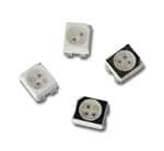
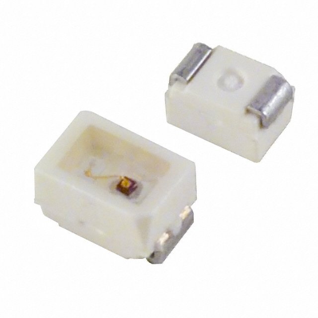
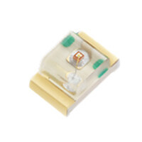
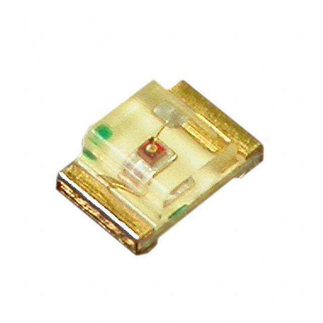
ICGOO电子元器件商城为您提供HSMF-A341-A00J1由Avago Technologies设计生产,在icgoo商城现货销售,并且可以通过原厂、代理商等渠道进行代购。 HSMF-A341-A00J1价格参考¥8.01-¥19.52。Avago TechnologiesHSMF-A341-A00J1封装/规格:LED 指示 - 分立, 红色,绿色,蓝色(RGB) 626nm 红色,525nm 绿色,470nm 蓝色 LED 指示 - 分立 1.9V 红色,3.4V 绿色,3.4V 蓝色 4-PLCC。您可以下载HSMF-A341-A00J1参考资料、Datasheet数据手册功能说明书,资料中有HSMF-A341-A00J1 详细功能的应用电路图电压和使用方法及教程。
型号为 HSMF-A341-A00J1 的 LED 指示器件由 Broadcom Limited 生产,属于 LED 指示 - 分立 类别。该型号的应用场景主要集中在需要高亮度、低功耗和稳定性能的指示灯领域。以下是其主要应用场景:

 1. 消费电子设备
   - 家用电器:如冰箱、洗衣机、空调等设备的状态指示灯,用于显示运行状态或报警信息。
   - 音频/视频设备:电视、音响、机顶盒等产品的电源指示灯或模式切换指示灯。
   - 便携式设备:例如充电宝、蓝牙音箱、耳机充电仓等的小型化指示灯。

 2. 工业控制
   - 机械设备:用于工业设备的操作面板上,作为电源、故障或运行状态的指示灯。
   - 自动化系统:在工厂自动化控制中,用于监控设备状态或报警提示。

 3. 通信设备
   - 网络设备:路由器、交换机、光纤收发器等设备上的信号强度、连接状态指示灯。
   - 基站设备:用于基站模块的状态指示,如电源、信号或数据传输状态。

 4. 汽车电子
   - 车内指示灯:如仪表盘上的警示灯、车门未关提示灯等。
   - 外部指示灯:部分小型 LED 指示灯可用于辅助功能,例如转向灯或刹车灯的备份指示。

 5. 医疗设备
   - 监测设备:如血压计、血糖仪等便携式医疗设备的状态指示灯。
   - 诊断仪器:用于显示仪器运行状态或测试结果。

 6. 安防设备
   - 监控摄像头:用于指示摄像头的工作状态(如录制中、待机等)。
   - 报警系统:用作报警触发时的视觉提示。

 特点与优势
- 高亮度:适合在各种光照条件下清晰可见。
- 低功耗:延长设备电池寿命,尤其适用于便携式产品。
- 长寿命:确保在长时间使用中保持稳定的性能。
- 紧凑设计:便于集成到小型化或空间受限的设备中。

综上,HSMF-A341-A00J1 型号的 LED 指示灯广泛应用于需要可靠、高效视觉反馈的各类场景,满足多样化的产品设计需求。
| 参数 | 数值 |
| 产品目录 | |
| 描述 | LED RED/GREEN/BLU 40MCD 5V 4PLCC标准LED-SMD Red/Grn/Blue Tri-Color |
| 产品分类 | |
| LED大小 | 3.2 mm x 2.8 mm x 1.9 mm |
| 品牌 | Avago Technologies |
| 产品手册 | |
| 产品图片 |
|
| rohs | 符合RoHS无铅 / 符合限制有害物质指令(RoHS)规范要求 |
| 产品系列 | LED发射器,标准LED-SMD,Avago Technologies HSMF-A341-A00J1- |
| 数据手册 | http://www.avagotech.com/docs/AV02-0501EN |
| 产品型号 | HSMF-A341-A00J1 |
| PCN组件/产地 | |
| PCN设计/规格 | http://www.avagotech.com/docs/V09-004-SD475420-0A |
| 产品种类 | 标准LED-SMD |
| 光强度 | 80 mcd, 160 mcd, 40 mcd |
| 其它名称 | 516-2231-1 |
| 包装 | 剪切带 (CT) |
| 商标 | Avago Technologies |
| 大小/尺寸 | 3.20mm 长 x 2.80mm 宽 |
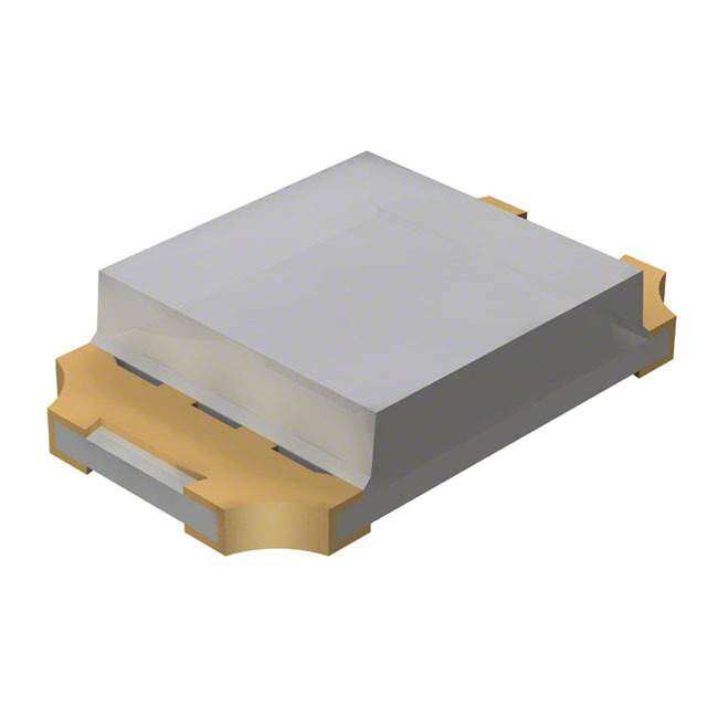
| 安装类型 | 表面贴装 |
| 封装 | Reel |
| 封装/外壳 | 4-PLCC |
| 封装/箱体 | PLCC-4 |
| 工厂包装数量 | 2000 |
| 显示角 | 120 deg |
| 最大工作温度 | + 100 C |
| 最小工作温度 | - 55 C |
| 标准包装 | 1 |
| 正向电压 | 1.9 V, 3.4 V, 3.4 V |
| 正向电流 | 20 mA |
| 毫烛光等级 | 80mcd 红,160mcd 绿,40mcd 蓝 |
| 波长-主 | 626nm,525nm,470nm |
| 波长-峰值 | 635nm,523nm,468nm |
| 波长/色温 | 626 nm, 525 nm, 470 nm |
| 测试电流时的光通量 | - |
| 照明颜色 | RGB |
| 电压-正向(Vf)(典型值) | 1.9V 红,3.4V 绿,3.4V 蓝 |
| 电流-测试 | 20mA |
| 视角 | 120° |
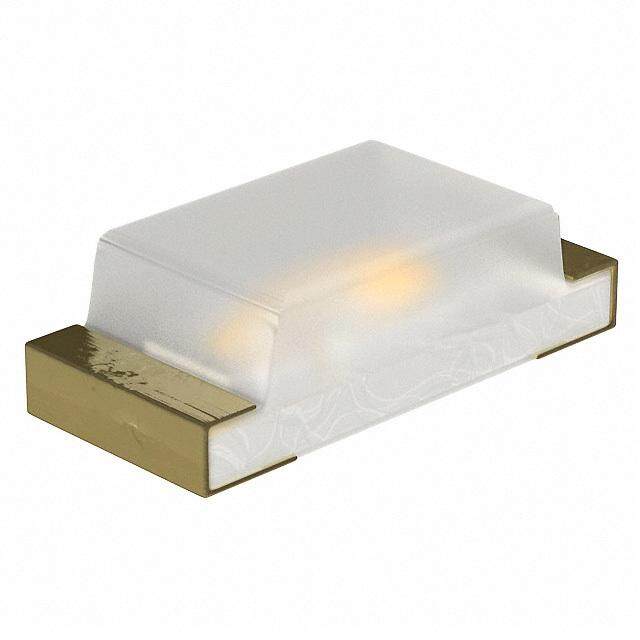
| 透镜样式/尺寸 | 圆形,带平顶,2.2mm |
| 透镜类型 | 透明 |
| 透镜颜色/类型 | Diffused |
| 颜色 | 红,绿,蓝(RGB) |
| 高度 | 2.10mm |


- 商务部:美国ITC正式对集成电路等产品启动337调查
- 曝三星4nm工艺存在良率问题 高通将骁龙8 Gen1或转产台积电
- 太阳诱电将投资9.5亿元在常州建新厂生产MLCC 预计2023年完工
- 英特尔发布欧洲新工厂建设计划 深化IDM 2.0 战略
- 台积电先进制程称霸业界 有大客户加持明年业绩稳了
- 达到5530亿美元!SIA预计今年全球半导体销售额将创下新高
- 英特尔拟将自动驾驶子公司Mobileye上市 估值或超500亿美元
- 三星加码芯片和SET,合并消费电子和移动部门,撤换高东真等 CEO
- 三星电子宣布重大人事变动 还合并消费电子和移动部门
- 海关总署:前11个月进口集成电路产品价值2.52万亿元 增长14.8%

PDF Datasheet 数据手册内容提取
HSMx-A2-xx-xxxxx Bi-Color HSMx-A3xx-xxxxx Tri-Color Surface Mount LED Indicators, PLCC-4 SMT LEDs Data Sheet Description Features This family of SMT LEDs is packaged in the industry stan- Industry Standard PLCC-4 package (Plastic Leaded Chip Carrier) dard PLCC-4 package. These SMT LEDs have high reliabil- ity performance and are designed to work under a wide High reliability LED package due to enhanced silicone range of environmental conditions. This high reliabil- resin material ity feature makes them ideally suited to be used under High brightness using AlInGaP and InGaN dice tech- harsh interior automotive as well as interior signs appli- nologies cation conditions. Available in full selection of colors To facilitate easy pick and place assembly, the LEDs are Super wide viewing angle at 120° packed in EIA-compliant tape and reel. Every reel will Available in 8 mm carrier tape on 7-inch reel be shipped in single intensity and color bin, except red color to provide close uniformity. Compatible with IR soldering process These LEDs are compatible with IR and TTW solder re- Applications fl ow process. Electronic signs and signals This super wide viewing angle at 120° together with the – Interior full color sign built in refl ector pushing up the intensity of the light – Variable message sign output makes these LED suitable to be used in the inte- rior electronics signs. The fl at top emitting surface makes Interior automotive it easy for these LEDs to mate with light pipes. This is – Instrument cluster backlighting suitable for general backlighting in automo tive interior, – Central console backlighting offi ce equipment, industrial equipment, and home ap- – Cabin backlighting pliances. Offi ce automation, home appliances, industrial equip- ment – Front panel backlighting – Display backlighting CAUTION: HSMF-Axxx-xxxxx LEDs are Class 2 ESD sensitive. Please observe appropriate precautions during handling and processing. Refer to Avago Application Note AN-1142 for additional details.
Package Dimensions 2.8 ± 0.2 1.9 ± 0.2 2.2 ± 0.2 0.1 TYP. 0.8 ± 0.1 (2) (3) 3.2 ± 0.2 3.5 ± 0.2 0.8 ± 0.3 (1) (4) 0.5 ± 0.1 0.7 ± 0.1 CATHODE MARKING NOTE: 1. ALL DIMENSIONS IN mm. Device Selection Guide Tri Color 1 Cathode (Color 1) Bi Color 2 Common Anode Part Number Color 1 Color 2 3 Cathode (Color 3) HSMF-A201- xxxxx GaP Red GaP Yellow Green 4 Cathode (Color 2) HSMF-A202- xxxxx GaP Red GaP Yellow Bi Color HSMF-A203- xxxxx GaP Red GaP Emerald Green 1 Cathode (Color 1) HSMF-A204- xxxxx GaP Orange GaP Yellow Green 2 Anode (Color 1) 3 Cathode (Color 2) HSMF-A205- xxxxx GaP Orange GaP Emerald Green 4 Anode (Color 2) HSMF-A206- xxxxx GaP Yellow GaP Yellow Green HSMF-A211- xxxxx AlGaAs Red GaP Yellow Green HSMF-A212- xxxxx AlGaAs Red GaP Yellow HSMF-A222- xxxxx AlInGaPRed AlInGaP Amber HSMF-A226- xxxxx AlInGaP Amber AlInGaP Yellow Green 2
Color 1 Color 2 Min. Iv @ 20 mA Typical Iv @ 20 mA Min. Iv @ 20 mA Typical Iv @ 20 mA Part Number Bin ID (mcd) (mcd) Bin ID (mcd) (mcd) HSMF-A201-A00J1 K2 9.0 16.0 L1 11.2 20.0 HSMF-A202-A00J1 K2 9.0 16.0 K1 7.2 12.0 HSMF-A203-A00J1 K2 9.0 16.0 J1 4.5 8.0 HSMF-A204-A00J1 K2 9.0 16.0 L1 11.2 20.0 HSMF-A205-A00J1 K2 9.0 16.0 J1 4.5 8.0 HSMF-A206-A00J1 K2 9.0 16.0 L1 11.2 20.0 HSMF-A211-A00J1 L2 14.0 25.0 L1 11.2 20.0 HSMF-A212-A00J1 L2 14.0 25.0 K1 7.2 12.0 HSMF-A222-A00J1 P1 45.0 80.0 P1 45.0 80.0 HSMF-A226-A00J1 P2 56.0 100.0 M2 22.4 60.0 Note: 1. The luminous intensity Iv, is measured at the mechanical axis of the lamp package. The actual peak of the spatial radiation pattern may not be aligned with this axis. 2. IV tolerance = ±10 %. Tri Color Part Number Color 1 Color 2 Color 3 HSMF-A341-xxxxx AllnGaP Red InGaN Green InGaN Blue Color 1 Color 2 Color 3 Min. Iv Typical Iv Min. Iv Typical Iv Min. Iv Typical Iv @ 20 mA @ 20 mA @ 20 mA @ 20 mA @ 20 mA @ 20 mA Part Number Bin ID (mcd) (mcd) Bin ID (mcd) (mcd) Bin ID (mcd) (mcd) K2 9.0 13.0 L2 14.0 20.0 K2 9.2 10.0 P1 45.0 80.0 R1 112.5 160.0 K2 9.2 10.0 P1 45.0 80.0 R1 112.5 160.0 K2 9.2 10.0 HSMF-A341-A00J1 P1 45.0 80.0 R1 112.5 160.0 N1 28.5 40.0 P1 45.0 80.0 R1 112.5 160.0 N1 28.5 40.0 Note: 1. The luminous intensity Iv, is measured at the mechanical axis of the lamp package. The actual peak of the spatial radiation pattern may not be aligned with this axis. 2. IV tolerance = ±10 %. 3
Part Numbering System HSM x – A x x x – x x x x x 1 2 3 4 5 6 7 8 9 Packaging Option Color Bin Selection Intensity Bin Select Device Specifi cation Confi guration Package Type LED Chip Color Absolute Maximum Ratings (T = 25°C) A AlInGaP Parameters GaP AlGaAs Red, Amber Yellow Green GaN/InGaN DC Forward Current[1] 30 mA 30 mA 30 mA[3,4] 20 mA[4] 20 mA Peak Forward Current[2] 100 mA 100 mA 100 mA 100 mA 100 mA Power Dissipation 78 mW 78 mW 72 mW 48 mW 120 mW Reverse Voltage 5 V Junction Temperature 110°C Operating Temperature –55°C to +100°C Storage Temperature –55°C to +100°C Notes: 1. Derate linearly as shown in fi gure 4. 2. Duty factor = 10%, Frequency = 1kHz. 3. Drive Current between 10 mA and 30 mA are recommended for best long term performance. 4. Operation at current below 5 mA is not recommended. 4
Optical Characteristics (T = 25°C) A Peak Dominant Luminous Luminous Intensity/ Wavelength Wavelength Viewing Angle Effi cacy v Total Flux PEAK (nm) D (nm)[1] 21/2 (Degrees)[2] (lm/W)[3] Iv (mcd) /v (mlm) Color Typ. Typ. Typ. Typ. Typ. GaP Red 635 626 120 120 0.45 AlGaAs Red 645 637 120 63 0.45 AlInGaP Red 635 626 120 150 0.45 AlInGaP Red Orange 621 615 120 240 0.45 GaP Orange 600 602 120 380 0.45 AlInGaP Amber 592 590 120 480 0.45 GaP Yellow 583 585 120 580 0.45 AlInGaP Amber 592 590 120 480 0.45 GaP Yellow Green 565 569 120 590 0.45 GaP Emerald Green 558 560 120 650 0.45 InGaN Green 523 525 120 500 0.45 InGaN Blue 468 470 120 75 0.45 GaN Blue 428 462 120 65 0.45 AlInGaP Yellow Green 575 571 120 620 0.45 Notes: 1. The dominant wavelength, D, is derived from the CIE Chromaticity Diagram and represents the color of the device. 2. 1/2 is the off -axis angle where the luminous intensity is 1/2 the peak intensity. 3. Radiant intensity, Ie in watts/steradian, may be calculated from the equation Ie = Iv/v, where Iv is the luminous intensity in candelas and v is the luminous effi cacy in lumens/watt. Electrical Characteristics (T = 25°C) A Forward Voltage Reverse Voltage Reverse Voltage VF (Volts) @ IF = 20mA VR @ 100 A VR @ 10 A Dice Technology Typ. Max. Min. Min. GaP 2.2 2.6 5 - AS AlGaAs 1.9 2.6 5 - AlInGaP 1.9 2.4 5 - GaN Blue 3.9 4.3 - 5 InGaN 3.4 4.05 - 5 5
1.0 BLUE YELLOW GREEN 0.9 CYAN AMBER 0.8 Y GREEN ORANGE SIT 0.7 N E 0.6 T N 0.5 E I V 0.4 LATI 0.3 RED ORANGE E RED R 0.2 0.1 0 380 430 480 530 580 630 680 730 780 WAVELENGTH – nm 1.0 GaP EMERALD GREEN 0.8 Y GaP GaP YELLOW NSIT YEGLRLEOEWN E 0.6 T E IN GaN BLUE GaP ORANGE V 0.4 TI A L E GaP RED R 0.2 0 380 430 480 530 580 630 680 730 780 WAVELENGTH – nm Figure 1. Relative intensity vs. wavelength 35 1.8 35 WARD CURRENT – mA 1321200055 AS AAllIGnGGaAaaPPs InGaN VE LUMINOUS INTENSITYRMALIZED AT 20 mA) 110101......806246 AAlIlnGGaAaPsGapGIanNGaN CURRENT – mA 2211305500 ASIn AGlIanNGG/GaaPPaN AlGaAs R GaN TIO 0.4 O BLUE AN F 5 EL( 0.2 5 R 0 0 0 0 1 2 3 4 5 0 5 10 15 20 25 30 35 0 20 40 60 80 100 120 FORWARD VOLTAGE – V DC FORWARD CURRENT – mA TEMPERATURE – °C Figure 2. Forward current vs. forward voltage Figure 3. Relative intensity vs. forward voltage Figure 4a. Maximum forward current vs. ambient temperature. Derated based on TJMAX = 110°C, RJA = 500°C/W (1 chip on) 6
A 35 540 m ENT – 30 GaP AlGaAs H – nm 553200 InGaN GREEN D CURR 2205 AS AlInGaP ELENGT 510 R V 500 A A W 15 W R InGaN/GaN T 490 O N F 10 A M N 480 U MI M 5 O 470 InGaN BLUE XI D A M 0 460 0 20 40 60 80 100 120 0 5 10 15 20 25 30 35 AMBIENT TEMPERATURE – °C CURRENT – mA Figure 4b. Maximum forward current vs. ambient Figure 5. Dominant wavelength vs. forward temperature. Derated based on TJMAX = 110°C, current – InGaN RJA = 700°C/W (3 chip on) 1.0 Y 0.8 T SI N E T 0.6 N D I E LIZ 0.4 A M R O 0.2 N 0 -90 -80 -70 -60 -50 -40 -30 -20 -10 0 10 20 30 40 50 60 70 80 90 ANGULAR DISPLACEMENT – DEGREES Figure 6. Radiation pattern 20 SEC. MAX. 240°C MAX. 3°C/SEC. MAX. RE 100-150°C 183°C U T A R PE 3°C/SEC. –6°C/SEC. M MAX. MAX. E T 120 SEC. MAX. 60-150 SEC. TIME Figure 7. Recommended SnPb refl ow soldering profi le Note: For detail information on refl ow soldering of Avago surface mount LEDs, do refer to Avago Application Note AN 1060 Surface Mounting SMT LED Indicator Components. 7
2.60 3.30 3.30 0.40 1.10 (cid:0)(cid:0)(cid:0)(cid:0)(cid:0)(cid:0) 0.50 4.50 (cid:0)(cid:0)(cid:0)(cid:0)(cid:0)(cid:0)(cid:0)7.50 1.50 (cid:0)(cid:0)(cid:0)(cid:0)(cid:0)(cid:0) SOLDER RESIST (cid:0)(cid:0)(cid:0)(cid:0)(cid:0)(cid:0) Figure 8. Recommended soldering pad pattern TRAILER COMPONENT LEADER 200 mm MIN. FOR ∅180 REEL. 480 mm MIN. FOR ∅180 REEL. 200 mm MIN. FOR ∅330 REEL. 960 mm MIN. FOR ∅330 REEL. C A USER FEED DIRECTION Figure 9. Tape leader and trailer dimension 4 ± 0.1 4 ± 0.1 2 ± 0.05 2.29 ± 0.1 1.75 ± 0.1 ∅1.5+0.1 –0 C 3.5 ± 0.05 +0.3 3.81 ± 0.1 8–0.1 A 3.05 ± 0.1 ∅1+0.1 –0 8° 0.229 ± 0.01 Figure 10. Tape leader and trailer dimension 8
Ø 20.5 ± 0.3 +0.5 2 –0 +0 62.5 180 –2.5 Ø 13 ± 0.2 +1.50 8.4 (MEASURED AT OUTER EDGE) –0.00 14.4 (MAX. MEASURED AT HUB) LABEL AREA (111 mm x 57 mm) WITH DEPRESSION (0.25 mm) 7.9 (MIN.) 10.9 (MAX.) Figure 11. Reel dimension USER FEED DIRECTION ID Note : Diameter "ID" should be bigger than 2.3mm CATHODE SIDE PRINTED LABEL Figure 12. Reeling Orientation Figure 13. Recommended Pick and Place Nozzle Size 9
Handling Precaution The encapsulation material of the product is made of B. Control after opening the MBB silicone for better reliability of the product. As silicone - The humidity indicator card (HIC) shall be read is a soft material, please do not press on the silicone or immediately upon opening of MBB. poke a sharp object onto the silicone. These might dam- - The LEDs must be kept at <30°C / 60%RH at all time age the product and cause premature failure. During as- and all high temperature related process including sembly of handling, the unit should be held on the body soldering, curing or rework need to be completed only. Please refer to Avago Application Note AN 5288 for within 672 hours. detail information. C. Control for unfi nished reel Moisture Sensitivity - For any unuse LEDs, they need to be stored in sealed This product is qualifi ed as Moisture Sensitive Level 2a MBB with desiccant or desiccator at <5%RH. per Jedec J-STD-020. Precautions when handling this D. Control of assembled boards moisture sensitive product is important to ensure the - If the PCB soldered with the LEDs is to be subjected reliability of the product. Do refer to Avago Application to other high temperature processes, the PCB Note AN5305 Handling of Moisture Sensitive Surface need to be stored in sealed MBB with desiccant Mount Devices for details. or desiccator at <5%RH to ensure no LEDs have A. Storage before use exceeded their fl oor life of 672 hours. - Unopen moisture barrier bag (MBB) can be stored E. Baking is required if: at <40°C/90%RH for 12 months. If the actual shelf - “10%” or “15%” HIC indicator turns pink. life has exceeded 12 months and the HIC indicates - The LEDs are exposed to condition of >30°C / 60% that baking is not required, then it is safe to refl ow RH at any time. the LEDs per the original MSL rating. - The LEDs fl oor life exceeded 672 hours. - It is not recommended to open the MBB prior to assembly (e.g. for IQC). Recommended baking condition: 60±5°C for 20 hours. 10
Iv Bin Select (X X ) 5 6 For For Individual reel will contain parts HSMF-A202-xxxxx HSMF-A203-xxxxx from 1 half bin only. HSMF-A205-xxxxx Minimum Intensity Bin X5 Min. Iv Bin Selection Color 1 Color 2 Minimum Intensity Bin For (Red) (Yellow) Color 1 Color 2 HSMF-A201-xxxxx (Red/Orange) (Green) A K2 K1 HSMF-A204-xxxxx A K2 J1 B K2 K2 HSMF-A206-xxxxx B K2 J2 C K2 L1 Minimum Intensity Bin C K2 K1 D K2 L2 Color 1 (Red/Yellow/ Color 2 E K2 M1 D K2 K2 Orange) (Green) E K2 L1 F L1 K1 A K2 L1 F L1 J1 G L1 K2 B K2 L2 G L1 J2 H L1 L1 C K2 M1 H L1 K1 J L1 L2 D K2 M2 J L1 K2 K L1 M1 E K2 N1 K L1 L1 L L2 K1 F L1 L1 L L2 J1 M L2 K2 G L1 L2 M L2 J2 N L2 L1 H L1 M1 N L2 K1 P L2 L2 J L1 M2 P L2 K2 Q L2 M1 K L1 N1 Q L2 L1 R M1 K1 L L2 L1 R M1 J1 S M1 K2 M L2 L2 S M1 J2 T M1 L1 N L2 M1 T M1 K1 U M1 L2 P L2 M2 U M1 K2 V M1 M1 Q L2 N1 V M1 L1 W M2 K1 R M1 L1 W M2 J1 X M2 K2 S M1 L2 X M2 J2 Y M2 L1 T M1 M1 Y M2 K1 Z M2 L2 U M1 M2 Z M2 K2 1 M2 M1 V M1 N1 1 M2 L1 W M2 L1 X M2 L2 Y M2 M1 Z M2 M2 1 M2 N1 11
For For For HSMF-A211-xxxxx HSMF-A212-xxxxx HSMF-A222-xxxxx Minimum Intensity Bin Minimum Intensity Bin Minimum Intensity Bin Color 1 Color 2 Color 1 Color 2 Color 1 Color 2 (Red) (Green) (Red) (Yellow) (Red) (Amber) A L2 L1 A L2 K1 A P1 P1 B L2 L2 B L2 K2 B P1 P2 C L2 M1 C L2 L1 C P1 Q1 D L2 M2 D L2 L2 D P1 Q2 E L2 N1 E L2 M1 E P1 R1 F M1 L1 F M1 K1 F P2 P1 G M1 L2 G M1 K2 G P2 P2 H M1 M1 H M1 L1 H P2 Q1 J M1 M2 J M1 L2 J P2 Q2 K M1 N1 K M1 M1 K P2 R1 L M2 L1 L M2 K1 L Q1 P1 M M2 L2 M M2 K2 M Q1 P2 N M2 M1 N M2 L1 N Q1 Q1 P M2 M2 P M2 L2 P Q1 Q2 Q M2 N1 Q M2 M1 Q Q1 R1 R N1 L1 R N1 K1 R Q2 P1 S N1 L2 S N1 K2 S Q2 P2 T N1 M1 T N1 L1 T Q2 Q1 U N1 M2 U N1 L2 U Q2 Q2 V N1 N1 V N1 M1 V Q2 R1 W N2 L1 W N2 K1 W R1 P1 X N2 L2 X N2 K2 X R1 P2 Y N2 M1 Y N2 L1 Y R1 Q1 Z N2 M2 Z N2 L2 Z R1 Q2 1 N2 N1 1 N2 M1 1 R1 R1 2 R2 P1 Note: 0 represents no maximum bin limit. 3 R2 P2 4 R2 Q1 5 R2 Q2 6 R2 R1 12
For X Number of Half bins from X For HSMF-A3xx-xxxxx 6 5 HSMF-A341-xxxxx For Color 1 Minimum Intensity Bin HSMF-A2xx-xxxxx (Red/Red Color 2 Color 3 Orange) (Green) (Blue) Color 1 Color 1 Color 2 (Red/Red Color 2 Color 3 0 0 0 0 0 0 0 Orange) (Green) (Blue) A 5 5 5 A 0 5 A P1 R1 N1 B 5 5 4 B 0 4 B P1 R1 N2 C 5 5 3 C 0 3 C P1 R1 P1 D 5 4 5 D 0 2 D P1 R2 N1 E 5 4 4 E 5 0 E P1 R2 N2 F 5 4 3 F 5 5 F P1 R2 P1 G 5 3 5 G 5 4 G P1 S1 N1 H 5 3 4 H 5 3 H P1 S1 N2 J 5 3 3 J 5 2 J P1 S1 P1 K 4 5 5 K 4 0 K P2 R1 N1 L 4 5 4 L 4 5 L P2 R1 N2 M 4 5 3 M 4 4 M P2 R1 P1 N 4 4 5 N 4 3 N P2 R2 N1 P 4 4 4 P 4 2 P P2 R2 N2 Q 4 4 3 Q 3 0 Q P2 R2 P1 R 4 3 5 R 3 5 R P2 S1 N1 S 4 3 4 S 3 4 S P2 S1 N2 T 4 3 3 T 3 3 T P2 S1 P1 U 3 5 5 U 3 2 U Q1 R1 N1 V 3 5 4 V 2 0 V Q1 R1 N2 W 3 5 3 W 2 5 W Q1 R1 P1 X 3 4 5 X 2 4 X Q1 R2 N1 Y 3 4 4 Y 2 3 Y Q1 R2 N2 Z 3 4 3 Z 2 2 Z Q1 R2 P1 1 3 3 5 Note: 0 represents no maximum bin limit. 1 Q1 S1 N1 2 3 3 4 2 Q1 S1 N2 3 3 3 3 3 Q1 S1 P1 Note: 0 represents no maximum bin limit. 4 Q2 R1 N1 5 Q2 R1 N2 6 Q2 R1 P1 7 Q2 R2 N1 8 Q2 R2 N2 9 Q2 R2 P1 13
Intensity Bin Limits Bin ID Min. (mcd) Max. (mcd) J1 4.50 5.60 J2 5.60 7.20 K1 7.20 9.00 K2 9.00 11.20 L1 11.20 14.00 L2 14.00 18.00 M1 18.00 22.40 M2 22.40 28.50 N1 28.50 35.50 N2 35.50 45.00 P1 45.00 56.00 P2 56.00 71.50 Q1 71.50 90.00 Q2 90.00 112.50 R1 112.50 140.00 R2 140.00 180.00 S1 180.00 224.00 S2 224.00 285.00 T1 285.00 355.00 T2 355.00 450.00 U1 450.00 560.00 U2 560.00 715.00 V1 715.00 900.00 V2 900.00 1125.00 Tolerance of each bin limit = ±10%. 14
Color Bin Select (X ) 7 For For Individual reel will contain parts HSMF-A205-xxxxx HSMF-A204-xxxxx from 1 full bin only. HSMF-A206-xxxxx Color 1 Color 2 X Color Bin Combinations (Yellow/Amber/ (Emerald Color 1 7 Orange) Green/Blue) (Yellow/ For Amber/ Color 2 HSMF-A202-xxxxx 0 0 0 Orange) (Yellow Green) HSMF-A203-xxxxx A ABC ABC HSMF-A212-xxxxx 0 0 0 B BCD ABC HSMF-A222-xxxxx A ABC EFG C CDE ABC Color 2 B BCD EFG Color 1 (Emerald Green/ D ABC BCD C CDE EFG (Red) Yellow/Blue) E BCD BCD D DEF EFG 0 0 0 F CDE BCD E ABC FGH A 0 ABC G ABC CDE F BCD FGH B 0 ABCD H BCD CDE G CDE FGH C 0 ABCDE J CDE CDE H DEF FGH D 0 BCD K DEF ABC J AB EF E 0 BCDE L DEF BCD K BC EF F 0 BCDEF M DEF CDE L CD EF G 0 CDE N AB AB M DE EF H 0 DEF P BC AB N EF EF J 0 CDEF Q CD AB P AB FG K 0 AB R DE AB Q BC FG L 0 BC S AB BC R CD FG M 0 CD T BC BC S DE FG N 0 DE U CD BC T EF FG P 0 EF V DE BC U AB GH W AB CD Note: 0 represents full distribution. V BC GH X BC CD W CD GH Y CD CD X DE GH Z DE CD Y EF GH For 1 AB DE HSMF-A201-xxxxx 2 BC DE Note: 0 represents full distribution. HSMF-A211-xxxxx 3 CD DE Color 1 Color 2 4 DE DE (Red) (Yellow Green) 5 EF AB 0 0 0 6 EF BC A 0 EFG 7 EF CD B 0 FGH C 0 EF Note: 0 represents full distribution. D 0 FG E 0 GH Note: 0 represents full distribution. 15
For HSMF-A3xx-xxxxx Color Bin Limits Color 1 Color 2 Color 3 Blue Min. (nm) Max. (nm) Amber/ Yellow Min. (nm) Max. (nm) 0 0 0 0 A 460.0 465.0 A 582.0 584.5 A 0 0 ABC B 465.0 470.0 B 584.5 587.0 B 0 0 BCD C 470.0 475.0 C 587.0 589.5 C 0 0 AB D 475.0 480.0 D 589.5 592.0 D 0 0 BC E 0 0 CD Green Min. (nm) Max. (nm) E 592.0 594.5 F 594.5 597.0 F 0 ABC 0 A 515.0 520.0 G 0 ABC ABC B 520.0 525.0 H 0 ABC BCD C 525.0 530.0 Orange Min. (nm) Max. (nm) J 0 ABC AB D 530.0 535.0 A 597.0 600.0 K 0 ABC BC B 600.0 603.0 L 0 ABC CD Emerald C 603.0 606.0 M 0 BCD 0 Green Min. (nm) Max. (nm) D 606.0 609.0 N 0 BCD ABC A 552.5 555.5 E 609.0 612.0 P 0 BCD BCD B 555.5 558.5 Q 0 BCD AB C 558.5 561.5 Red Orange Min. (nm) Max. (nm) R 0 BCD BC D 561.5 564.5 A 611.0 616.0 S 0 BCD CD B 616.0 620.0 T 0 AB ABC Yellow Green Min. (nm) Max. (nm) U 0 AB BCD Red Min. (nm) Max. (nm) V 0 AB AB E 564.5 567.5 W 0 AB BC F 567.5 570.5 Full Distribution X 0 AB CD G 570.5 573.5 Tolerance of each bin limit = ±1 nm. Y 0 BC ABC H 573.5 576.5 Z 0 BC BCD 1 0 BC AB 2 0 BC BC Packaging Option (X X ) 8 9 3 0 BC CD X X 8 9 4 0 CD ABC J1 20 mA test current, Top Mount, 7 inch Reel 5 0 CD BCD 6 0 CD AB 7 0 CD BC 8 0 CD CD Note: 0 represents full distribution. For product information and a complete list of distributors, please go to our website: www.avagotech.com Avago, Avago Technologies, and the A logo are trademarks of Avago Technologies in the United States and other countries. Data subject to change. Copyright © 2005-2012 Avago Technologies. All rights reserved. Obsoletes 5989-1210EN AV02-0501EN - February 2, 2012
Mouser Electronics Authorized Distributor Click to View Pricing, Inventory, Delivery & Lifecycle Information: B roadcom Limited: HSMF-A201-A00J1 HSMF-A202-A00J1 HSMF-A203-A00J1 HSMF-A204-A00J1 HSMF-A205-A00J1 HSMF-A206- A00J1 HSMF-A211-A00J1 HSMF-A212-A00J1 HSMF-A222-A00J1 HSMF-A341-A00J1