ICGOO在线商城 > 光电元件 > LED 指示 - 分立 > HSMC-A101-S00J1
/HSMC-A101-S00J1.jpg)
 Datasheet下载
- 型号: HSMC-A101-S00J1
- 制造商: Avago Technologies
- 库位|库存: xxxx|xxxx
- 要求:
| 数量阶梯 | 香港交货 | 国内含税 |
| +xxxx | $xxxx | ¥xxxx |
查看当月历史价格
查看今年历史价格
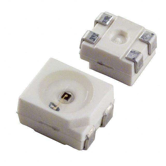
HSMC-A101-S00J1产品简介:
ICGOO电子元器件商城为您提供HSMC-A101-S00J1由Avago Technologies设计生产,在icgoo商城现货销售,并且可以通过原厂、代理商等渠道进行代购。 HSMC-A101-S00J1价格参考¥1.53-¥6.54。Avago TechnologiesHSMC-A101-S00J1封装/规格:LED 指示 - 分立, 红色 626nm LED 指示 - 分立 1.9V 2-PLCC。您可以下载HSMC-A101-S00J1参考资料、Datasheet数据手册功能说明书,资料中有HSMC-A101-S00J1 详细功能的应用电路图电压和使用方法及教程。
Broadcom Limited的HSMC-A101-S00J1是一款分类为LED指示 - 分立的产品,其应用场景主要包括以下领域:

 1. 状态指示
   - 该型号的LED指示灯通常用于设备的状态指示功能。例如,在网络设备(如路由器、交换机)中,它可以显示电源状态、数据传输活动或端口连接情况。
   - 在消费电子设备(如音响、电视、家用电器)中,用于指示设备是否开启、运行模式或故障报警。

 2. 工业控制
   - 在工业自动化设备中,这款LED可用于监控机器运行状态,例如启动/停止信号、警报提示或生产线状态反馈。
   - 它也可以集成到人机界面(HMI)面板上,作为按钮或开关的状态指示。

 3. 通信设备
   - HSMC-A101-S00J1适用于电信和数据通信设备,例如光纤收发器、调制解调器等,用于指示信号强度、链路状态或错误信息。
   - 在基站或无线通信设备中,它可以用作模块状态或同步状态的指示灯。

 4. 汽车电子
   - 在汽车内部仪表盘或控制面板中,这款LED可以用于指示油量、温度、故障代码或其他关键参数。
   - 它还可能应用于车内氛围灯系统中的某些分立指示功能。

 5. 医疗设备
   - 在医疗仪器中,这款LED可用作设备运行状态、电池电量或报警提示的指示灯,确保医护人员能够快速了解设备的工作状况。

 6. 安防监控
   - 在摄像头、门禁系统或报警装置中,该LED可以用于指示工作状态、录像活动或触发警报。

 特点与优势
- 高可靠性:Broadcom Limited的产品以高稳定性著称,适合长时间运行的应用场景。
- 低功耗:分立式LED设计有助于降低整体能耗,延长设备使用寿命。
- 紧凑尺寸:便于集成到各种小型化或紧凑型设备中。

总之,HSMC-A101-S00J1凭借其高性能和稳定性,广泛应用于需要清晰、可靠状态指示的各种电子设备中。
| 参数 | 数值 |
| 产品目录 | |
| 描述 | LED 635NM RED 2-PLCC SMD标准LED-SMD Red Epoxy Lens 626nm 220mcd |
| 产品分类 | |
| LED大小 | 3.2 mm x 2.8 mm x 1.9 mm |
| 品牌 | Avago Technologies US Inc. |
| 产品手册 | |
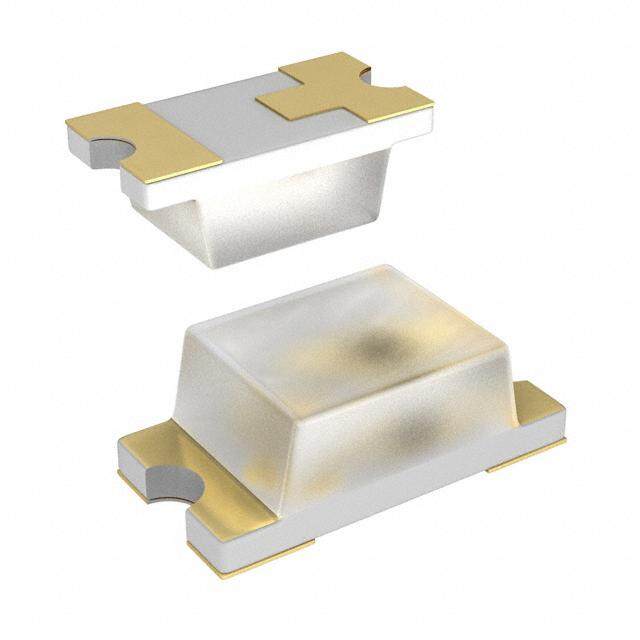
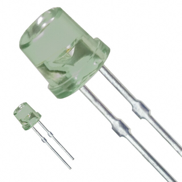
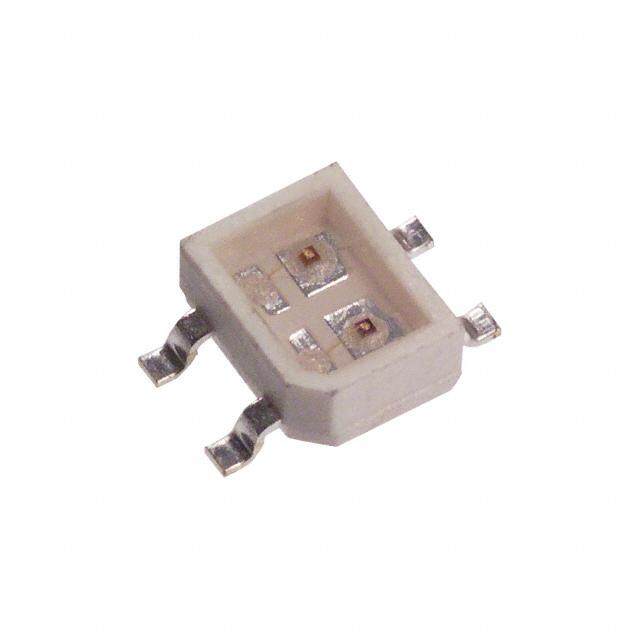
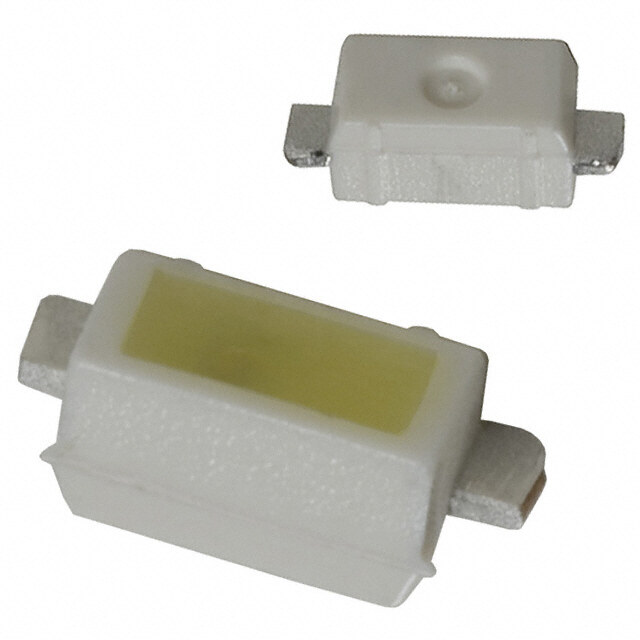
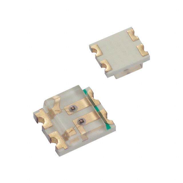
| 产品图片 |
|
| rohs | 符合RoHS无铅 / 符合限制有害物质指令(RoHS)规范要求 |
| 产品系列 | LED发射器,标准LED-SMD,Avago Technologies HSMC-A101-S00J1- |
| 数据手册 | http://www.avagotech.com/docs/AV02-0198EN |
| 产品型号 | HSMC-A101-S00J1 |
| 产品目录绘图 |
|
| 产品目录页面 | |
| 产品种类 | 标准LED-SMD |
| 光强度 | 220 mcd |
| 其它名称 | 516-2122-2 |
| 包装 | 带卷 (TR) |
| 商标 | Avago Technologies |
| 大小/尺寸 | 3.20mm 长 x 2.80mm 宽 |
| 安装类型 | 表面贴装 |
| 封装 | Reel |
| 封装/外壳 | 2-PLCC |
| 封装/箱体 | PLCC-2 |
| 工厂包装数量 | 2000 |
| 显示角 | 120 deg |
| 最大工作温度 | + 100 C |
| 最小工作温度 | - 55 C |
| 标准包装 | 2,000 |
| 正向电压 | 1.9 V |
| 正向电流 | 20 mA |
| 毫烛光等级 | 220mcd |
| 波长-主 | 626nm |
| 波长-峰值 | 635nm |
| 波长/色温 | 626 nm |
| 测试电流时的光通量 | 690 mlm |
| 照明颜色 | Red |
| 电压-正向(Vf)(典型值) | 2.4V |
| 电流-测试 | 20mA |
| 视角 | 120° |
| 透镜样式/尺寸 | 圆形,带平顶,2.2mm |
| 透镜类型 | 透明 |
| 透镜颜色/类型 | Clear |
| 颜色 | 红 |
| 高度 | 1.90mm |


- 商务部:美国ITC正式对集成电路等产品启动337调查
- 曝三星4nm工艺存在良率问题 高通将骁龙8 Gen1或转产台积电
- 太阳诱电将投资9.5亿元在常州建新厂生产MLCC 预计2023年完工
- 英特尔发布欧洲新工厂建设计划 深化IDM 2.0 战略
- 台积电先进制程称霸业界 有大客户加持明年业绩稳了
- 达到5530亿美元!SIA预计今年全球半导体销售额将创下新高
- 英特尔拟将自动驾驶子公司Mobileye上市 估值或超500亿美元
- 三星加码芯片和SET,合并消费电子和移动部门,撤换高东真等 CEO
- 三星电子宣布重大人事变动 还合并消费电子和移动部门
- 海关总署:前11个月进口集成电路产品价值2.52万亿元 增长14.8%
PDF Datasheet 数据手册内容提取
HSMx-A10x-xxxxx PLCC-2, Surface Mount LED Indicator Data Sheet Description Features This family of SMT LEDs is packaged in the industry • Industry standard PLCC-2 package standard PLCC-2 package. These SMT LEDs have high • High reliability LED package reliability performance and are designed to work under • High brightness using AlInGaP and InGaN dice tech- a wide range of environmental conditions. This high nologies reliability feature makes them ideally suited to be used under harsh interior automotive as well as interior signs • Available in full selection of colors application conditions. • Super wide viewing angle at 120˚ To facilitate easy pick & place assembly, the LEDs • Available in 8 mm carrier tape on 7 inch reel (2000 are packed in EIA-compliant tape and reel. Every reel will pieces) be shipped in single intensity and color bin, except red • Compatible with both IR and TTW soldering process color, to provide close uniformity. Applications These LEDs are compatible with IR solder reflow process. Due to the high reliability feature of these products, they • Interior automotive can also be mounted using through-the-wave soldering – Instrument panel backlighting process. – Central console backlighting – Cabin backlighting The super wide viewing angle at 120˚ makes these LEDs ideally suited for panel, push button, or general • Electronic signs and signals backlighting in automotive interior, office equipment, – Interior full color sign industrial equipment, and home appliances. The flat – Variable message sign top emitting surface makes it easy for these LEDs • Office automation, home appliances, industrial to mate with light pipes. With the built-in reflector equipment pushing up the intensity of the light output, these LEDs – Front panel backlighting are also suitable to be used as LED pixels in interior elec- – Push button backlighting tronic signs. – Display backlighting CAUTION: HSMN,M,K and E-A10x-xxxxx LEDs are Class 2 ESD sensitive. Please observe appropriate precau- tions during handling and processing. Refer to Avago Application Note AN-1142 for additional details.
Package Dimensions 2.8 ± 0.2 1.9 ± 0.2 2.2 ± 0.2 0.1 TYP. 0.8 ± 0.1 3.2 ± 0.2 3.5 ± 0.2 0.8 ± 0.3 0.5 ± 0.1 CATHODE MARKING (ANODE MARKING FOR AlGaAs DEVICES) TOP MOUNT 2.8 ± 0.2 1.9 ± 0.2 2.2 ± 0.2 3.2 ± 0.2 5.2 ± 0.2 0.1 TYP. CATHODE MARKING 0.5 ± 0.1 REVERSE MOUNT NOTE: ALL DIMENSIONS IN MILLIMETERS. 2
Table 1. Device Selection Guide Red Part Number Min IV (mcd) Typ. IV (mcd) Max. IV (mcd) Test Current (mA) Dice Technology HSMS-A100-J00J1 4.50 15.00 - 20 GaP HSMS-A100-L00J1 11.20 15.00 - 20 GaP HSMS-A100-J80J2 5.60 - 14.00 10 GaP HSMH-A100-L00J1 11.20 15.00 - 20 AlGaAs HSMH-A100-N00J1 28.50 50.00 - 20 AlGaAs HSMC-A100-Q00J1 71.50 100.00 - 20 AlInGaP HSMC-A100-R00J1 112.50 140.00 - 20 AlInGaP HSMC-A101-S00J1 180.00 220.00 - 20 AlInGaP HSMZ-A100-T00J1 285.00 350.00 - 20 AlInGaP Red Orange Part Number Min IV (mcd) Typ. IV (mcd) Max. IV (mcd) Test Current (mA) Dice Technology HSMJ-A100-Q00J1 71.50 100.00 - 20 AlInGaP HSMJ-A101-S00J1 180.00 200.00 - 20 AlInGaP HSMJ-A100-T40J1 285.00 - 715.00 20 AlInGaP HSMV-A100-T00J1 285.00 350.00 - 20 AlInGaP HSMJ-A100-R40J1 112.50 - 285.00 20 AlInGaP Orange Part Number Min IV (mcd) Typ. IV (mcd) Max. IV (mcd) Test Current (mA) Dice Technology HSMD-A100-J00J1 4.50 15.00 - 20 GaP HSMD-A100-L00J1 11.20 15.00 - 20 GaP HSMD-A100-K4PJ2 7.20 - 18.00 10 GaP HSML-A100-Q00J1 71.50 100.00 - 20 AlInGaP HSML-A101-S00J1 180.00 220.00 - 20 AlInGaP Yellow / Amber Part Number Min IV (mcd) Typ. IV (mcd) Max. IV (mcd) Test Current (mA) Dice Technology HSMY-A100-J00J1 4.50 12.00 - 20 GaP HSMY-A100-L00J1 11.20 12.00 - 20 GaP HSMA-A100-Q00J1 71.50 100.00 - 20 AlInGaP HSMA-A101-S00J1 180.00 220.00 - 20 AlInGaP HSMU-A100-S00J1 180.00 320.00 - 20 AlInGaP HSMA-A101-R8WJ1 140.00 - 355.00 20 AlInGaP 3
Table 1. Device Selection Guide (Cont.) Yellow Green Part Number Min IV (mcd) Typ. IV (mcd) Max. IV (mcd) Test Current (mA) Dice Technology HSMG-A100-J02J1 4.50 18.00 - 20 GaP HSMG-A100-K72J2 9.00 - 18.00 10 GaP HSME-A100-M02J1 18.00 70.00 - 20 AlInGaP HSME-A100-N82J1 35.50 - 90.00 20 AlInGaP Emerald Green Part Number Min IV (mcd) Typ. IV (mcd) Max. IV (mcd) Test Current (mA) Dice Technology HSMG-A100-H01J1 2.80 8.00 - 20 GaP HSME-A100-L01J1 11.20 40.00 - 20 AlInGaP HSME-A100-M3PJ1 18.00 - 35.50 20 AlInGaP Green Part Number Min IV (mcd) Typ. IV (mcd) Max. IV (mcd) Test Current (mA) Dice Technology HSMM-A101-R00J1 112.50 200.00 - 20 InGaN HSMM-A100-S00J1 180.00 350.00 - 20 InGaN HSMM-A100-U4PJ1 450.00 - 1125.00 20 InGaN Blue Part Number Min IV (mcd) Typ. IV (mcd) Max. IV (mcd) Test Current (mA) Dice Technology HSMN-A101-N00J1 28.50 50.00 - 20 InGaN HSMN-A100-P00J1 45.00 70.00 - 20 InGaN HSMN-A100-R4YJ1 112.50 - 285.00 20 InGaN HSMN-A100-S4YJ1 180.00 - 450.00 20 InGaN HSMN-A100-R8YJ1 140.00 - 355.00 20 InGaN 4
Part Numbering System HSM x1 - A x2 x3x4 - x5x6 x7 x8x9 Packaging Option Color Bin Selection Intensity Bin Select Device Specific Configuration Package Type LED Chip Color Absolute Maximum Ratings (TA = 25°C) Parameters HSMS/D/Y/G HSMH HSMC/J/L/A HSME HSMZ/V/U HSMM/N DC Forward Current [1] 30 mA 30 mA 30 mA [3,4] 20 mA [4] 30 mA [3,4] 30 mA Peak Forward Current [2] 100 mA 100 mA 100 mA 100 mA 100 mA 100 mA Power Dissipation 63 mW 60 mW 63 mW 48 mW 63 mW 114 mW Reverse Voltage 5 V Junction Temperature 110°C Operating Temperature –55°C to +100°C Storage Temperature –55°C to +100°C Notes: 1. Derate linearly as shown in Figure 4. 2. Duty factor = 10%, Frequency = 1 kHz. 3. Drive current between 10 mA and 30 mA is recommended for best long term performance. 4. Operation at current below 5 mA is not recommended. 5
Optical Characteristics (T = 25˚C) A Luminous Peak Dominant Viewing Angle Luminous Intensity/ Wavelength Wavelength [1] 2 θ1/2 [2] Efficacy ηv [3] Total Flux Dice λPEAK (nm) λD (nm) (Degrees) (lm/W) Iv(mcd)/Φv(mlm) Color Part Number Technology Typ. Typ. Typ. Typ. Typ. Red HSMS-A100 GaP 635 626 120 120 0.45 HSMH-A100 AlGaAs 645 637 120 63 0.45 HSMC-A10x AlInGaP 635 626 120 150 0.45 HSMZ-A100 AlInGaP 635 626 120 155 0.45 Red HSMJ-A10x AlInGaP 621 615 120 240 0.45 Orange HSMV-A100 AlInGaP 623 617 120 263 0.45 Orange HSMD-A100 GaP 600 602 120 380 0.45 HSML-A10x AlInGaP 609 605 120 320 0.45 Amber HSMY-A100 GaP 583 585 120 520 0.45 HSMA-A10x AlInGaP 592 590 120 480 0.45 HSMU-A100 AlInGaP 594 592 120 500 0.45 Yellow HSMG-A100 GaP 565 569 120 590 0.45 Green HSME-A100 AlInGaP 575 570 120 560 0.45 Emerald HSMG-A100 GaP 558 560 120 650 0.45 Green HSME-A100 AlInGaP 566 560 120 610 0.45 Green HSMM-A10x InGaN 523 525 120 500 0.45 Blue HSMN-A10x InGaN 468 470 120 75 0.45 Notes: 1. The dominant wavelength, λD, is derived from the CIE Chromaticity Diagram and represents the color of the device. 2. θ1/2 is the off-axis angle where the luminous intensity is 1/2 the peak intensity. 3. Radiant intensity, Ie in watts/steradian, may be calculated from the equation Ie = Iv/ηv, where Iv is the luminous intensity in candelas and ηv is the luminous efficacy in lumens/watt. Electrical Characteristics (T = 25˚C) A Forward Voltage VF (Volts) @ IF = 20 mA Reverse Voltage Reverse Voltage Thermal VR @ 100 μA VR @ 10 μA Resistance Part Number Typ. Max. Min. Min. RθJP (°C/W) HSMS/D/Y/G 2.2 2.6 5 — 180 HSMH 1.9 2.6 5 — 180 HSMC/J/L/A/E 1.9 2.4 5 — 280 HSMZ/V/U 1.9 2.4 5 — 280 HSMM/N 3.4 4.05 — 5 280 6
1.0 BLUE EMERALD GREEN 0.9 YELLOW GREEN 0.8 GREEN AMBER 0.7 NSITY 0.6 NTE 0.5 RELATIVE I 00..34 ORERDA NOGREANGE RED 0.2 0.1 0 380 430 480 530 580 630 680 730 780 WAVELENGTH – nm 1.0 GaP EMERALD GREEN 0.8 GaP GaP YELLOW YELLOW NSITY0.6 GREEN NTE GaP ORANGE ATIVE I0.4 REL GaP RED 0.2 0 380 430 480 530 580 630 680 730 780 WAVELENGTH – nm Figure 1. Relative intensity vs. wavelength. 35 1.8 1.6 Gap 30 WARD CURRENT – mA212055 HSMC/JH/LS/MAS/E/HD/ZS//YMV/HG/U HSMM/N VE LUMINOUS INTENSITYRMALIZED AT 20 mA) 01011.....80624 AAlIlnGGaaAPs InGaN FOR10 RELATI(NO 0.4 5 0.2 0 0 0 1 2 3 4 5 0 5 10 15 20 25 30 35 FORWARD VOLTAGE – V DC FORWARD CURRENT – mA Figure 2. Forward current vs. forward voltage. Figure 3. Relative intensity vs. forward current. 35 35 30 30 HSMS/D/G/ HSMS/D/G/Y/H Y/H/Z/V/U 25 25 HSMC/J/L/A A HSMC/J/L/A A HSMZ/V/U NT - m20 HSME NT - m 20 HSME HSMM/N RE15 RE 15 UR HSMM/N UR C C 10 10 5 5 0 0 0 20 40 60 80 100 120 0 20 40 60 80 100 120 TEMPERATURE (°C) TEMPERATURE (°C) Figure 4. Maximum forward current vs. ambient temperature. Derated Figure 4b. Maximum Forward Current Vs. Solder Point Temperature. De- based on TJMAX = 110˚C, RθJA = 500˚C/W. rated based on TJMAX = 110°C, RθJP = 180°C/W or 280°C/W. 7
540 0.5 530 NGTH – nm 551200 GREEN D AT 25°C) 000...423 NT WAVELE 540900 CYAN NORMALIZE 0.10 GaP/AlGaAs/ MINA 480 A V (F-0.1 AlInGaP DO 470 BLUE DELT -0.2 InGaN/GaN 460 -0.3 0 5 10 15 20 25 30 35 -100 -50 0 50 100 150 CURRENT – mA TEMPERATURE – °C Figure 5. Dominant wavelength vs. forward current – InGaN devices. Figure 6. Forward voltage shift vs. temperature. 1.0 0.8 NTENSITY 0.6 D I ALIZE 0.4 M R O N 0.2 0 -90 -80 -70 -60 -50 -40 -30 -20 -10 0 10 20 30 40 50 60 70 80 90 ANGULAR DISPLACEMENT – DEGREES Figure 7. Radiation Pattern. TURBULENT WAVE LAMINAR WAVE HOT AIR KNIFE 250 10 to 30 SEC. 255 - 260 C 200 EMPERATURE 221105700 CCC 3 C/SEC. MAX. 6 C/SEC. MAX. MPERATURE – C150 FLUXING T E100 T 3 C/SEC. MAX. BOTTOM SIDE OF PC BOARD 50 60 - 120 SEC. 100 SEC. MAX. 30 TOP SIDE OF PREHEAT PC BOARD 0 10 20 30 40 50 60 70 80 90 100 TIME TIME – SECONDS (Acc. to J-STD-020C) CONVEYOR SPEED = 1.83 M/MIN (6 FT/MIN) Figure 8. Recommended Pb-free reflow soldering profile. PREHEAT SETTING = 150C (100C PCB) SOLDER WAVE TEMPERATURE = 245C AIR KNIFE AIR TEMPERATURE = 390C Note: For detail information on reflow soldering of Avago surface AIR KNIFE DISTANCE = 1.91 mm (0.25 IN.) mount LEDs, do refer to Avago Application Note AN 1060 Surface AIR KNIFE ANGLE = 40 LEADED SOLDER: SN63; FLUX: RMA Mounting SMT LED Indicator Components. LEAD-FREE SOLDER: 96.5 wt% SN, 3 wt% Ag, 0.5 wt% Cu Reflow soldering must not be done more than 2 times. Do observe NOTE: ALLOW FOR BOARDS TO BE SUFFICIENTLY COOLED necessary precautions of handling moisture sensitive device as stated BEFORE EXERTING MECHANICAL FORCE. in below section. Figure 9. Recommended wave soldering profile. 8
4.50 1.50 2.60 SOLDER RESIST Figure 10. Recommended soldering pad pattern TRAILER COMPONENT LEADER 200 mm MIN. FOR Ø180 REEL. 480 mm MIN. FOR Ø180 REEL. 200 mm MIN. FOR Ø330 REEL. 960 mm MIN. FOR Ø330 REEL. C A USER FEED DIRECTION Figure 11. Tape leader and trailer dimensions 4 ± 0.1 4 ± 0.1 2 ± 0.05 2.29 ± 0.1 1.75 ± 0.1 +0.1 Ø 1.5 –0 C 3.5 ± 0.05 +0.3 3.81 ± 0.1 8 –0.1 A +0.1 3.05 ± 0.1 Ø1 –0 8° 0.229 ± 0.01 Figure 12. Tape dimensions 9
Ø 20.5 ± 0.3 2+0.5 –0 +0 62.5 180 –2.5 Ø 13 ± 0.2 +1.50 8.4 – 0 . 0 0 (MEASURED AT OUTER EDGE) 14.4 (MAX. MEASURED AT HUB) LABEL AREA (111 mm x 57 mm) 7.9 (MIN.) WITH DEPRESSION (0.25 mm) 10.9 (MAX.) Figure 13. Reel dimensions. USER FEED DIRECTION CATHODE SIDE PRINTED LABEL Figure 14. Reeling orientation. 10
Intensity Bin Select (X X ) Intensity Bin Limits 5 6 Individual reel will contain parts Bin ID Min. (mcd) Max. (mcd) from one half bin only. G1 1.80 2.24 X5 Min Iv Bin G2 2.24 2.80 H1 2.80 3.55 X6 H2 3.55 4.50 0 Full Distribution J1 4.50 5.60 2 2 half bins starting from X51 J2 5.60 7.20 3 3 half bins starting from X51 K1 7.20 9.00 4 4 half bins starting from X51 K2 9.00 11.20 5 5 half bins starting from X51 L1 11.20 14.00 6 2 half bins starting from X52 L2 14.00 18.00 7 3 half bins starting from X52 M1 18.00 22.40 8 4 half bins starting from X52 M2 22.40 28.50 N1 28.50 35.50 9 5 half bins starting from X52 N2 35.50 45.00 P1 45.00 56.00 P2 56.00 71.50 Q1 71.50 90.00 Q2 90.00 112.50 R1 112.50 140.00 R2 140.00 180.00 S1 180.00 224.00 S2 224.00 285.00 T1 285.00 355.00 T2 355.00 450.00 U1 450.00 560.00 U2 560.00 715.00 V1 715.00 900.00 V2 900.00 1125.00 W1 1125.00 1400.00 W2 1400.00 1800.00 X1 1800.00 2240.00 X2 2240.00 2850.00 Tolerance of each bin limit = ± 12% 11
Color Bin Select (X ) Color Bin Limits Color Bin Limits 7 Individual reel will contain parts Blue Min. (nm) Max. (nm) Amber Min. (nm) Max. (nm) from one full bin only. A 460.0 465.0 A 582.0 584.5 X7 B 465.0 470.0 B 584.5 587.0 0 Full Distribution C 470.0 475.0 C 587.0 589.5 Z A and B only D 475.0 480.0 D 589.5 592.0 Y B and C only E 592.0 594.5 W C and D only F 594.5 597.0 Cyan Min. (nm) Max. (nm) V D and E only A 490.0 495.0 U E and F only B 495.0 500.0 Orange Min. (nm) Max. (nm) T F and G only C 500.0 505.0 A 597.0 600.0 S G and H only D 505.0 510.0 B 600.0 603.0 Q A, B, and C only C 603.0 606.0 P B, C, and D only D 606.0 609.0 N C, D, and E only Green Min. (nm) Max. (nm) E 609.0 612.0 M D, E, and F only A 515.0 520.0 L E, F, and G only B 520.0 525.0 K F, G, and H only C 525.0 530.0 Red Orange Min. (nm) Max. (nm) 1 A, B, C, and D only D 530.0 535.0 A 611.0 616.0 2 E, F, G, and H only B 616.0 620.0 3 B, C, D, and E only 4 C, D, E, and F only Emerald Min. (nm) Max. (nm) 5 A, B, C, D, and E only Green Red Min. (nm) Max. (nm) 6 B, C, D, E, and F only A 552.5 555.5 Full Distribution B 555.5 558.5 Tolerance of each bin limit = ± 1 nm. C 558.5 561.5 D 561.5 564.5 Yellow Green Min. (nm) Max. (nm) E 564.5 567.5 F 567.5 570.5 G 570.5 573.5 H 573.5 576.5 12
Packaging Option (X X ) Moisture Sensitivity 8 9 Option Test Current Package Type Reel Size This product is qualified as Moisture Sensitive Level 2a J1 20 mA Top Mount 7 inch per Jedec J-STD-020. Precautions when handling this moisture sensitive product is important to ensure the J4 20 mA Top Mount 13 inch reliability of the product. Do refer to Avago Application H1 20 mA Reverse Mount 7 inch Note AN5305 Handling of Moisture Sensitive Surface H4 20 mA Reverse Mount 13 inch Mount Devices for details. J2 10 mA Top Mount 7 inch A. Storage before use J5 10 mA Top Mount 13 inch - Unopen moisture barrier bag (MBB) can be stored H2 10 mA Reverse Mount 7 inch at <40°C/90%RH for 12 months. If the actual shelf H5 10 mA Reverse Mount 13 inch life has exceeded 12 months and the HIC indicates L2 2 mA Top Mount 7 inch that baking is not required, then it is safe to reflow the LEDs per the original MSL rating. - It is not recommended to open the MBB prior to assembly (e.g. for IQC). B. Control after opening the MBB - The humidity indicator card (HIC) shall be read im- mediately upon opening of MBB. - The LEDs must be kept at <30°C / 60%RH at all time and all high temperature related process including soldering, curing or rework need to be completed within 672 hours. C. Control for unfinished reel - For any unuse LEDs, they need to be stored in sealed MBB with desiccant or desiccator at <5%RH. D. Control of assembled boards - If the PCB soldered with the LEDs is to be subjected to other high temperature processes, the PCB need to be stored in sealed MBB with desiccant or desic- cator at <5%RH to ensure no LEDs have exceeded their floor life of 672 hours. E. Baking is required if: - “10%” is Not blue and “5%” HIC indicator turns pink. - The LEDs are exposed to condition of >30°C / 60% RH at any time. - The LEDs floor life exceeded 672 hours. Recommended baking condition: 60±5°C for 20 hours. For product information and a complete list of distributors, please go to our website: www.avagotech.com Avago, Avago Technologies, and the A logo are trademarks of Avago Technologies in the United States and other countries. Data subject to change. Copyright © 2005-2015 Avago Technologies. All rights reserved. Obsoletes AV01-0040EN AV02-0198EN - January 19, 2015