.jpg)
 Datasheet下载
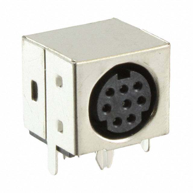
- 型号: HR10A-10R-12PB(72)
- 制造商: Hirose Electric
- 库位|库存: xxxx|xxxx
- 要求:
| 数量阶梯 | 香港交货 | 国内含税 |
| +xxxx | $xxxx | ¥xxxx |
查看当月历史价格
查看今年历史价格
HR10A-10R-12PB(72)产品简介:
ICGOO电子元器件商城为您提供HR10A-10R-12PB(72)由Hirose Electric设计生产,在icgoo商城现货销售,并且可以通过原厂、代理商等渠道进行代购。 HR10A-10R-12PB(72)价格参考。Hirose ElectricHR10A-10R-12PB(72)封装/规格:圆形连接器, 12 位置 圆形连接器 插座,公形引脚 焊接 金。您可以下载HR10A-10R-12PB(72)参考资料、Datasheet数据手册功能说明书,资料中有HR10A-10R-12PB(72) 详细功能的应用电路图电压和使用方法及教程。
Hirose Electric Co Ltd的HR10A-10R-12PB(72)是一款圆形连接器,广泛应用于工业设备、测试测量仪器及自动化控制系统中。其密封性能良好,适用于需要防尘防水的复杂环境。该连接器具备可靠的电气性能和机械耐久性,适合用于信号传输与电源连接场景。常见应用包括工厂自动化设备、机器人系统、医疗仪器以及户外电子装置等。由于其插拔方便、接触稳定,也常用于需要频繁连接与断开的设备中,如测试平台和移动设备接口。
| 参数 | 数值 |
| 产品目录 | |
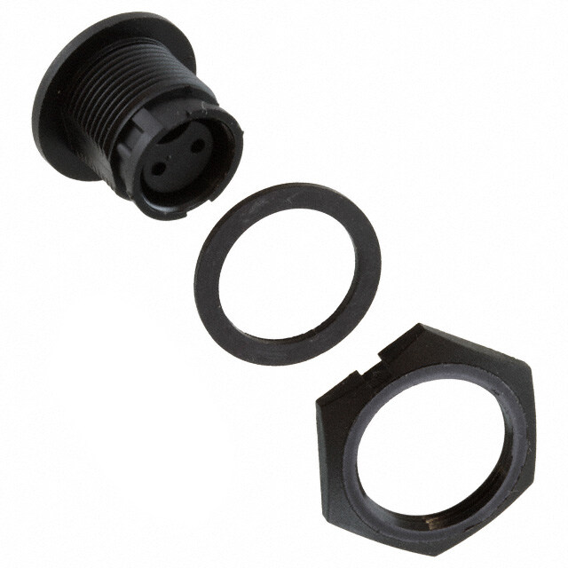
| 描述 | CONN RECEPT 12POS MALE DIP GOLD环形推拉式连接器 REC 12POS MALE DIP GOLD |
| 产品分类 | |
| 品牌 | Hirose Connector |
| 产品手册 | |
| 产品图片 |
|
| rohs | 符合RoHS无铅 / 符合限制有害物质指令(RoHS)规范要求 |
| 产品系列 | 环形推拉式连接器,Hirose Connector HR10A-10R-12PB(72)HR10A |
| 数据手册 | |
| 产品型号 | HR10A-10R-12PB(72) |
| 产品目录绘图 |
|
| 产品目录页面 | |
| 产品种类 | 环形推拉式连接器 |
| 产品类型 | Connectors |
| 侵入防护 | - |
| 其它名称 | *HR10A-10R-12PB(72) |
| 包装 | 散装 |
| 商标 | Hirose Connector |
| 外壳大小 | 10 |
| 外壳尺寸-插件 | 10 |
| 外壳尺寸,MIL | - |
| 外壳材料,镀层 | 黄铜和锌,镀镍 |
| 外壳材质 | Metal |
| 外壳电镀 | Nickel |
| 外壳类型 | Receptacle |
| 安装类型 | 面板安装,隔墙式通孔 |
| 安装风格 | Through Hole |
| 工作温度 | -25°C ~ 85°C |
| 工厂包装数量 | 1 |
| 朝向 | 带标记 |
| 标准包装 | 60 |
| 特性 | - |
| 电压-额定 | 100VAC |
| 电压额定值 | 100 V |
| 电流额定值 | 2 A |
| 相关产品 | /product-detail/zh/HR10A-10R-N/HR10A-10R-N-ND/3978296/product-detail/zh/HR10A-10R-W/HR10A-10R-W-ND/3978295/product-detail/zh/HR10-10R-C/HR349-ND/510206 |
| 端接 | |
| 端接类型 | Solder |
| 系列 | HR10 |
| 紧固类型 | 推挽式 |
| 触头镀层 | 金 |
| 触头镀层厚度 | - |
| 触点数量 | 12 |
| 触点电镀 | Gold |
| 触点类型 | Pin (Male) |
| 连接器类型 | Receptacle |
| 配套产品 | /product-detail/zh/HR10A-10PD-12S(74)/HR10A-10PD-12S(74)-ND/4306660/product-detail/zh/HR10A-10PA-12S(74)/HR10A-10PA-12S(74)-ND/4306655/product-detail/zh/HR10A-10P-12S(78)/HR10A-10P-12S(78)-ND/4284927/product-detail/zh/HR10A-10P-12SC(73)/HR1675-ND/1095533/product-detail/zh/HR10A-10P-12S(74)/HR1624-ND/1095482 |
| 针脚数 | 12 |
| 额定电流 | 2A |

.JPG)


.jpg)


- 商务部:美国ITC正式对集成电路等产品启动337调查
- 曝三星4nm工艺存在良率问题 高通将骁龙8 Gen1或转产台积电
- 太阳诱电将投资9.5亿元在常州建新厂生产MLCC 预计2023年完工
- 英特尔发布欧洲新工厂建设计划 深化IDM 2.0 战略
- 台积电先进制程称霸业界 有大客户加持明年业绩稳了
- 达到5530亿美元!SIA预计今年全球半导体销售额将创下新高
- 英特尔拟将自动驾驶子公司Mobileye上市 估值或超500亿美元
- 三星加码芯片和SET,合并消费电子和移动部门,撤换高东真等 CEO
- 三星电子宣布重大人事变动 还合并消费电子和移动部门
- 海关总署:前11个月进口集成电路产品价值2.52万亿元 增长14.8%


.jpg)
PDF Datasheet 数据手册内容提取
High performance miniature circular connectors HR10 Series Features 1. A simple, yet highly reliable design for compact, high density applications Although small in size, the HR10 series are full featured connectors with a well integrated design. 2. Extremely easy mating/unmating d. operations e rv Easy to operable, the single-action push-pull lock e s structure allows for quick and efficient locking and e R unlocking. s ht g Ri All D. Product Specifi cations T L Shell size No. of contacts Rated current O., 4 C C 7 5 2A RI Ratings 6 T C 10 E 10 2A L 12 E E 13 20 2A S O R HI Shell size No. of contacts Rated voltage 9 1 4 AC150V, DC200V 0 2 7 5 AC100V, DC140V ght Ratings 6 AC100V, DC140V ri py 10 o 10 AC100V, DC140V C 12 9 13 20 AC100V, DC140V 1 0 2 1. Operation temperature range -25 to +85ç ar. Ratings M Storage temperature range -10 to +60ç Items Specifications Conditions 1. Contact resistance 10mø min. Measured at DC 1A 2. Insulation resistance 1,000Mø min. Measured at DC 100V 3. Withstanding voltage No flashover or dielectric breakdown. AC 300V for one minute, 4 contacts : AC 500V for 1 minute 10 to 55Hz/cycle, amplitude : 0.75mm, 3 axis directions, 4. Vibration resistance No electrical discontinuity of 10µs or greater for 2 hours each Acceleration : 490m/s2, duration : 11ms 3 directions, 5. Shock resistance No electrical discontinuity of 10µs or greater 3 times each 6. Mating Cycles Contact resistance : 15mø min. 1,000 times -55ç : 30minutes➝Normal temperature : 10 to 15 minutes➝ 7. Temperature cycle Insulation resistance : 1,000Mø min. 85ç : 30minutes➝Normal temperature : 10 to 15minutes, left for 5 cycles. 5Mø min. (at high humidity) Temperature : 40ç, relative humidity : 90 to 95%, 8. Humidity resistance 50Mø min. (at dry) left for 96 hours Ipnl ecaassee sc ownhtaecret ath ceo ampppalincya trieopnr ewsielln dteamtivaen fdo ar fhuirgthh eler vineflo orfm raetliiaobni.lity, such as automotive, 2017.12y 1
HR10 Series●High performance miniature circular connectors Materials / Finish Items Material Finish Remarks Exterior Zinc alloy, brass Matte finished nickel plating ---------------- Insulator Polyamide resin, PBT resin ---------------- Blue, Black HR10 : Gold plating Contact Copper alloy ---------------- HR10A : Silver plating Product Number Structure Refer to the chart below when determining the product specifications from the product number. Please select from the product numbers listed in this catalog when placing orders. d. e HR10A - 7 P - 3 P C (**) v r e s q w e r t y u e R hts qModel name : Indicates the HR10A Series. The part type is identified as follows. g HR10A : Lower cost type Ri All HHRR1100GB :: SChoiaexldia tly cpoentact type D. T wShell size : The shell size is the outer shell diameter or the mating interface end of the plug. L O., eShell type C P : Plug C R : Receptacle RI J : Jack T C E rNumber of contacts L E E tContact form S P : Male contact O S : Female contact R HI yContact termination method: 9 1 None : Solder termination 0 2 C : Crimp termination ht g uOther specifications : A two-digit character is added to indicate other specifications as needed. ri y p o C 9 1 0 2 1. r. a M 2
HR10 Series●High performance miniature circular connectors Diagrams of Connectors in Combination Male Pin side Female Pin side (HR10 • HR10A HR10G Type Receptacle) (HR10 Type Plug) d. e v r e s e R s ht g Ri (HR10 Type Jack) All D. T L O., (HR10A Type Plug) C C RI T C (HR10A Type Jack) E L E E S O R HI (HR10B Type Receptacle) 9 1 0 2 (HR10B Type Plug) ht g ri y p o C 9 1 0 2 (HR10A-[ ]T Type Receptacle) 1. r. a M (HR10A-[ ]T Type Plug) (HR10A-[ ]T Type Jack) Notes 1 : When using a plug with male terminal, be sure to use a receptacle or jack fi tted with female terminal. 2 : Standard fi nish of the terminal is gold plating for the HR10, and silver plating for the HR10A and HR10G. Be sure to use male and female connectors of the same plating. 3
HR10 Series●High performance miniature circular connectors HR10 type HR10 type connectors, use a gold plated contact as the standard plating specification. Silver plating is used on the contacts for other series such as HR10A and HR10G. To avoid mixing gold and silver contacts, please be sure to confirm the plating specification when using HR10 type connectors with HR10A or HR10G connectors. Plug A Max d. e v BC D r ØØ Ø e s e R s ht g Ri HR10-7P-6S(73) All (Representative example) D. Unit : mm T L Part No. HRS No. No. of Contacts A ØB ØC ØD Weight O., HR10-7P-4P(73) 110-0021-6 73 C 4 C HR10-7P-4S(73) 110-0022-9 73 RI HR10-7P-6P(73) 110-0023-1 73 28.5 11 7 5.2 8g T 6 C HR10-7P-6S(73) 110-0024-4 73 E L E HR10-10P-12P(73) 110-0025-7 73 E HR10-10P-12S(73) 110-0026-0 73 12 32.5 14 9.5 7.2 15g S O R HI 9 Receptacle 1 0 2 ht A g ri 6.3 5.7 y p o C 9 1 20 ØB ØC 1. r. a M D HR10-7R-6S(73) E(HEX) (Representative example) Unit : mm Part No. HRS No. No. of Contacts A ØB ØC D E Weight HR10-7R-4S(73) 110-0031-0 73 4 HR10-7R-4P(73) 110-0032-2 73 14 11 8.85 M8×0.5 10 3.5g HR10-7R-6S(73) 110-0033-5 73 6 HR10-7R-6P(73) 110-0034-8 73 HR10-10R-12S(73) 110-0035-0 73 12 16 14 11.9 M11×0.75 13 6g HR10-10R-12P(73) 110-0036-3 73 Remarks : For mounting holes, see page 20. 4
HR10 Series●High performance miniature circular connectors Receptacle (PCB dip type) G E 5.7 F A B Ø Ø Dip post dia. Ø0.55 C D(HEX) HR10-7R-6SA(73) d. (Representative example) e rv Unit : mm e es Part No. HRS No. No. of Contacts ØA ØB C D E F G Weight R s HR10-7R-4SA(73) 110-0059-9 73 4 ght HR10-7R-6SA(73) 110-0050-4 73 11 8.85 M8×0.5 10 3g Ri 6 HR10-7R-6PA(73) 110-0061-0 73 6.3 0.5 15.5 All HR10-10R-12SA(73) 110-0049-5 73 D. 12 14 11.9 M11×0.75 13 5g T HR10-10R-12PA(73) 110-0055-8 73 L O., R emarks : 21.. FFoorr dmipo upnotsint ga rhroalnegse, mseeen tp, asgeee 2p0a.ge 16. C C RI T C Jack E L E E A Max S O 5.5 R HI 9 1 0 B C D 2 Ø Ø Ø ht g ri y p o C 9 HR10-7J-6S(73) 1 0 (Representative example) 2 1. Unit : mm r. a M Part No. HRS No. No. of Contacts A ØB ØC ØD Weight HR10-7J-4S(73) 110-0027-2 73 4 HR10-7J-4P(73) 110-0028-5 73 28.5 11 8.85 5.2 7g HR10-7J-6S(73) 110-0029-8 73 6 HR10-7J-6P(73) 110-0030-7 73 HR10-10J-12S(73) 110-0037-6 73 12 32.5 14 11.9 7.2 14g HR10-10J-12P(73) 110-0038-9 73 5
HR10 Series●High performance miniature circular connectors HR10A•10G Types HR10A connectors are a lower-cost version, yet still provide a high "Value Add" while preserving the superior characteristics of the HR10 connectors. Cable clamps are crimped using a special crimping tool, and the shells have a rubber boot which provides a flexible design that helps to prevent cable twisting. The HR10G connector is a shielded type connector which has an internal contacting structure between the plug shell and receptacle shell. Contacts in both HR10A and 10G connectors are silver plated as standard. Plug (Solder type) A d. e v r e B C D s Ø Ø Ø e R s ht g Ri (Representative example) All HR10A-7P-6P(73) D. Unit : mm T L Part No. HRS No. No. of Contacts A ØB ØC ØD Weight O., HR10A-7P-4P(73) 110-0301-2 73 C 4 C HR10A-7P-4S(73) 110-0302-5 73 RI HR10A-7P-5P(73) 110-0318-5 73 T 5 35 11.5 7 5 9g C HR10A-7P-5S(73) 110-0319-8 73 E HR10A-7P-6P(73) 110-0303-8 73 EL 6 HR10A-7P-6S(73) 110-0304-0 73 E S HR10A-10P-10P(73) 110-0407-3 73 O 10 R HR10A-10P-10S(73) 110-0408-6 73 HI HR10A-10P-12P(73) 110-0401-7 73 43 14.7 9.5 16g 9 12 7 1 HR10A-10P-12S(73) 110-0402-0 73 0 2 HR10A-13P-20P(73) 110-0713-0 73 ht HR10A-13P-20S(73) 110-0716-8 73 20 59 19 13 37g g ri y p o C Plug(Crimp type) 9 1 0 2 1. A r. a M B C D Ø Ø Ø HR10A-7P-6PC(73) (Representative example) Unit : mm Part No. HRS No. No. of Contacts A ØB ØC ØD Weight HR10A-7P-4PC(73) 110-0501-1 73 4 HR10A-7P-4SC(73) 110-0502-4 73 35 11.5 7 5 9g HR10A-7P-6PC(73) 110-0503-7 73 6 HR10A-7P-6SC(73) 110-0504-0 73 HR10A-10P-10PC(73) 110-0601-6 73 10 HR10A-10P-10SC(73) 110-0602-9 73 43 14.7 9.5 16g HR10A-10P-12PC(73) 110-0603-1 73 12 7 HR10A-10P-12SC(73) 110-0604-4 73 HR10A-13P-20PC(73) 110-0701-0 73 20 59 19 13 37g HR10A-13P-20SC(73) 110-0702-3 73 6
HR10 Series●High performance miniature circular connectors Receptacle (Solder type) A F 5.7 B C Ø Ø D E(HEX) HR10A-7R-6S(73) (Representative example) Unit : mm Part No. HRS No. No. of Contacts A ØB ØC D E E Weight Remarks HR10A-7R-4S(73) 110-0305-3 73 d. HR10A-7R-4P(73) 110-0306-6 73 4 e v HR10A-7R-5S(73) 110-0320-7 73 er 5 14 11 8.85 M8×0.5 10 3g s HR10A-7R-5P(73) 110-0321-0 73 e R HR10A-7R-6S(73) 110-0307-9 73 6 6.3 s HR10A-7R-6P(73) 110-0308-1 73 ht HR10A-10R-10S(71) 110-0409-9 71 g 10 Ri HR10A-10R-10P(73) 110-0410-8 73 All HR10A-10R-12S(71) 110-0403-2 71 12 16 14 11.9 M11×0.75 13 5g D. HR10A-10R-12P(73) 110-0404-5 73 T HR10A-13R-20S(73) 110-0714-2 73 20 19.2 18 15.4 M14×0.75 17 9.3 8g L HR10A-13R-20P(73) 110-0715-5 73 20.2 O., HR10G-7R-4S(73) 110-1601-1 73 4 C HR10G-7R-4P(73) 110-1602-4 73 C HR10G-7R-6S(73) 110-1605-2 73 14 11 8.85 M8×0.5 10 3g RI 6 HR10G-7R-6P(73) 110-1606-5 73 T 6.3 Shield type C HR10G-10R-10S(71) 110-1607-8 71 E 10 L HR10G-10R-10P(73) 110-1608-0 73 E HR10G-10R-12S(71) 110-1609-3 71 16 14 11.9 M11×0.75 13 5g E 12 S HR10G-10R-12P(73) 110-1610-2 73 O Remarks : For mounting holes, see page 20. R HI 9 Receptacle (Crimp type) F 1 0 E 2 ht g ri y p o A B C Ø Ø 9 1 0 2 1. C ar. HR10A-10R-12SC(71) (Representative example) D(HEX) M Unit : mm Part No. HRS No. No. of Contacts ØA ØB C D E F Weight Remarks HR10A-7R-4SC(73) 110-0506-5 73 12 4 HR10A-7R-4PC(73) 110-0505-2 73 12.2 11 8.85 M8×0.5 10 3g HR10A-7R-6SC(73) 110-0508-0 73 12 6 HR10A-7R-6PC(73) 110-0507-8 73 12.2 6.3 HR10A-10R-10SC(71) 110-0606-0 71 12 10 HR10A-10R-10PC(71) 110-0605-7 71 12.2 14 11.9 M11×0.75 13 5g HR10A-10R-12SC(71) 110-0608-5 71 12 12 HR10A-10R-12PC(71) 110-0607-2 71 12.2 HR10A-13R-20SC(73) 110-0703-6 73 20 18 15.4 M14×0.75 17 9.3 15 8g HR10A-13R-20PC(73) 110-0704-9 73 HR10G-7R-4SC(73) 110-1701-6 73 12 4 HR10G-7R-4PC(73) 110-1702-9 73 12.2 11 8.85 M8×0.5 10 3g HR10G-7R-6SC(73) 110-1705-7 73 12 6 HR10G-7R-6PC(73) 110-1706-0 73 12.2 6.3 HR10G-10R-10SC(71) 110-1707-2 71 12 10 Shield type HR10G-10R-10PC(71) 110-1708-5 71 12.2 14 11.9 M11×0.75 13 5g HR10G-10R-12SC(71) 110-1709-8 71 12 12 HR10G-10R-12PC(71) 110-1710-7 71 12.2 HR10G-13R-20SC(73) 110-1711-0 73 20 18 15.4 M14×0.75 17 9.3 15 8g HR10G-13R-20PC(73) 110-1712-2 73 Remarks : For mounting holes, see page 20. 7
HR10 Series●High performance miniature circular connectors Receptacle (Dip type) G E 5.7 F A B Ø Ø Dip post dia. 0.2∞0.5 C HR10A-7R-6SB(73) (Representative example) D(HEX) d. Unit : mm e v er Part No. HRS No. No. of ØA ØB C D E F G Weight Remarks s Contacts e R s HR10A-7R-4SB(73) 110-0314-4 73 4 ht HR10A-7R-4PB(73) 110-0315-7 73 g 3g Ri HR10A-7R-5SB(73) 110-0322-2 73 5 11 8.85 M8×0.5 10 All HR10A-7R-6SB(73) 110-0316-0 73 D. HR10A-7R-6PB(73) 110-0317-2 73 6 6.3 0.5 15.6 T L HR10A-10R-10SB(71) 110-0413-6 71 O., HR10A-10R-10PB(71) 110-0414-9 71 10 14 11.9 M11×0.75 13 5g C HR10A-10R-12SB(71) 110-0415-1 71 C 12 RI HR10A-10R-12PB(71) 110-0416-4 71 T HR10A-13R-20SB(73) 110-0707-7 73 C 20 18 15.4 M14×0.75 17 9.3 0 17.8 8g E HR10A-13R-20PB(73) 110-0708-0 73 L E HR10G-7R-4SB(73) 110-1801-0 73 E 4 HR10G-7R-4PB(73) 110-1802-3 73 S 11 8.85 M8×0.5 10 3g O HR10G-7R-6SB(73) 110-1805-1 73 R 6 HI HR10G-7R-6PB(73) 110-1806-4 73 6.3 0.5 15.6 9 HR10G-10R-10SB(71) 110-1807-7 71 Shield 1 10 0 HR10G-10R-10PB(71) 110-1808-0 71 type ht 2 HR10G-10R-12SB(71) 110-1809-2 71 14 11.9 M11×0.75 13 5g g 12 ri HR10G-10R-12PB(71) 110-1810-1 71 y p HR10G-13R-20SB(73) 110-1811-4 73 Co 20 18 15.4 M14×0.75 17 9.3 0 17.8 8g HR10G-13R-20PB(73) 110-1812-7 73 9 1 Remarks : 1. For mounting holes, see page 20. 20 2. For dip post arrangement, see page 16. 1. r. a M Dust cap 2 E Ø ØC 1 B 2 ØD 0. HR10-7R-C ØA (Representative example) Unit : mm Part No. HRS No. ØA B ØC ØD ØE HR10-7R-C 110-0058-6 00 11 7 8 11.2 13 HR10-10R-C 110-0052-0 00 14 8.5 10.8 14.1 15 HR10A-13R-C 110-0452-8 00 17.5 11.5 14 18.1 19 8
HR10 Series●High performance miniature circular connectors Jack (Solder type) A 5.5 B C D Ø Ø Ø HR10A-7J-6S(73) (Representative example) d. e v r Unit : mm e s e Part No. HRS No. No. of Contacts A ØB ØC ØD Weight R s HR10A-7J-4S(73) 110-0309-4 73 ht 4 g HR10A-7J-4P(73) 110-0310-3 73 Ri 35.3 11 8.85 5 9g All HR10A-7J-6S(73) 110-0311-6 73 6 D. HR10A-7J-6P(73) 110-0312-9 73 T HR10A-10J-10S(73) 110-0411-0 73 L 10 O., HR10A-10J-10P(73) 110-0412-3 73 43.5 14 11.9 7 16g C HR10A-10J-12S(73) 110-0405-8 73 C 12 RI HR10A-10J-12P(73) 110-0406-0 73 T C E L E Jack (Crimp type) E S O R A HI D 9 1 0 2 ht B C E g Ø Ø Ø ri y p o C 9 1 0 1.2 HR10A-7J-6SC(73) (Representative example) r. a M Unit : mm Part No. HRS No. No. of Contacts A ØB ØC D ØE Weight HR10A-7J-4SC(73) 110-0510-2 73 4 35.3 11 8.85 5 9g HR10A-7J-6SC(73) 110-0512-8 73 6 5.5 HR10A-10J-10SC(73) 110-0610-7 73 10 43.5 14 11.9 16g HR10A-10J-12SC(73) 110-0612-2 73 12 7 HR10A-13J-20SC(73) 110-0705-1 73 20 58.5 18 15.4 8.5 37g HR10A-13J-20PC(73) 110-0706-4 73 9
HR10 Series●High performance miniature circular connectors HR10B Type Connector The HR10B connector combines 10 signal lines and one coaxial contact in the standard number 10 shell. Performance specifications for the coaxial contacts are on the 11 page. Plug 7 4. B 1 Ø d. Ø e v r e A s e R s ht g Ri HR10B-10P-10PC(73) (Representative example) All D. Unit : mm T Part No. HRS No. A ØB Applicable coaxial contact L O., HR10B-10P-10PC(73) 110-0901-0 73 50 5 HR10B-2.5CJ(73) C HR10B-10PA-10PC(73) 110-0906-3 73 43 7 C RI T C E Receptacle L E E S O R 19 HI Ø14 Ø11.9 0 2 ght 6.3 M11∞0.75 ri 13(HEX) py 12 o C 9 1 HR10B-10R-10SC(71) 0 2 (Representative example) 1. ar. Unit : mm M Part No. HRS No. Applicable coaxial contact HR10B-10R-10SC(71) 110-0902-2 71 HR10B-2.5CP(73) Remarks : For mounting holes, see page 20. 10
HR10 Series●High performance miniature circular connectors Coaxial contacts The coaxial contacts shown here are for use with the HR10B connector.These contacts have locking barbs and are inserted from the rear of connector.Please use the following information to select the correct terminals. Materials / Finish Performance Part Material Finish Description Test data Plug shell Impedance 50ø Brass Gold plating Jack shell Insulation resistance 1000Mø or more at DC250V Insulator Tetrafl uoride resin Contact resistance Center 6.5mø or less and outer 4mø or less at DC1A Male pin Phosphor bronze Withstanding voltage AC250V r.m.s for 1minute d. Female pin Beryllium copper Gold plating V.S.W.R 1.3 or less for 0 to 1000MHz e v er Pull force 4.9N (500gf) or more s e R s ht Plug g Ri All 5.2 3.6 D. 1 T 4. L O., (clamp) C C 18.05 RI 7.1 1 T 1. C Ø E E EL Ø3.8 Ø4.2 S HR10B-2.5CP(73) O (Representative example) R HI 9 Unit : mm 1 0 Part No. HRS No. Applicable cable Applicable connector 2 ht HR10B-2.5CP(73) 110-0904-8 73 0.8D-QEW-CW(By Fjikura wire) HR10B-10R-10SC(71) g ri y p o C Jack 9 1 20 5.2 3.6 1. r. 1 Ma 4. (clamp) 18.2 7.25 1 1. Ø Ø2.65 Ø4.2 HR10B-2.5CJ(73) (Representative example) Unit : mm Part No. HRS No. Applicable cable Applicable connector HR10B-2.5CJ(73) 110-0903-5 73 0.8D-QEW-CW(By Fjikura wire) HR10B-10P-10PC(73) 11
HR10 Series●High performance miniature circular connectors Cable connecting methods HR10B-2.5CP(73) HR10B-2.5CJ(73) 1. Cable end treatment Fig.1 11±0.5 1. Dimensions for cable end treatment are shown in Fig 1. 2. Termination is described below. (1) Strip cable outer jacket as indicated. (2) Slit outer jacket on both sides per Fig.1. (3) Fold back outer cover. d. (4) Remove insulator from cable. e v er 1.4±0.2 s e R (2.5) 3.7±0.2 s ht g Ri Slit cable outer jaket All 2 pieces (180° reverse side) D. T L O., C C 2. Soldering male pin to cable center conductor RI T Fig.2 C E Male pin 1. Solder male pin to cable center conductor as indicated in Fig.2. L E (1) Pre-solder the solder pot of pin with Ø0.5mm string solder. E (2) Male pin should fit flush against the cable insulator as S O Soldering shown. R HI (3) Remove any excess solder from the pin with a knife.This 9 surface must be smooth. 1 (4) A properly soldered terminal will yield 500gf when stretched. 0 2 ht g ri y p o Should fix flush C 9 1 0 Contact fixing jig such as vise 2 1. r. a M 3. Crimping cable outer conductor Fig.3 1. Insert the cable into the connector and make sure to push it 15±0.2 all the way in. To confirm that the cable is fully inserted, make sure that the depth is 1.5 ± 0.2mm by measuring from the end of the connector to the tip of the male contact by using a vernier calipers or other suitable measuring device. 2. Use the HR10-TC-01 tool to crimp the metal fitting to the cable. Clamp Connector Remove excess insulator material (remaining after clamping is complated) with a knife or aimilarobject. 12
HR10 Series●High performance miniature circular connectors HR10A-( )T Type (Threaded Coupling Type) HR10A-( )T connector is a new product having a threaded coupling locking mechanism. Electric parformance is same as HR10 and HR10A push-pull locking type connectors. Plug (Solder type) D ØA BØC ØE d. e v r e s e R s ht HR10A-10TP-12P(73) g (Representative example) Ri All Unit : mm D. Part No. HRS No. No. of Contacts ØA B ØC D ØE Remarks HR10A-7TP-6P(73) 110-0331-3 73 T L 6 12 M10×0.75 7 35 5 O., HHRR1100AA--71T0TPP-6-P12(7P4()73) 111100--00343312--30 7743 Gold plating C 17 M13×0.75 43 7 C HR10A-10TPA-12S(73) 110-0446-5 73 12 9.5 RI HR10A-10WTP-12P(73) 110-1101-9 73 T 15 M12×0.75 45.8 6.5 * C HR10A-10WTP-12S(73) 110-1106-2 73 E L HR10A-13TPD-20P(73) 110-1015-9 73 20 20 M17×1 13 56.5 7 E E *Waterproof plug need resin fi lling inside when connector assembly. S When mated, the connector against water penetration. O R HI 9 Plug (Crimp type) 1 0 2 ht 43 g ri y p o C 5 019 Ø17 13∞0.7 Ø9.5 Ø7 2 M 1. r. a M HR10A-10TP-12PC(73) (Representative example) Unit : mm Part No. HRS No. No. of Contacts HR10A-10TP-12PC(73) 110-0455-6 73 12 13
HR10 Series●High performance miniature circular connectors Receptacle (Solder type) E B 5.7 D Ø C A HR10A-10TR-12S(73) F(HEX) (Representative example) Unit : mm d. Part No. HRS No. No. of Contacts A B C ØD E F Remarks e v r HR10-7TR-6S(73) 110-0089-0 73 6 M10×0.75 M8×0.5 11 14 10 Gold plating e 6.3 s e HR10A-10TR-12S(73) 110-0453-0 73 M13×0.75 M11×0.75 R 12 14 16 13 s HR10A-10WTR-12S(73) 110-1104-7 73 M12×0.75 6.8 M10.5×0.75 ht g Remarks : For mounting hole, see page 15(10TR,10WTR) 20(7TR). Ri All Receptacle (Crimp type) D. B T L C O., C C RI T A C Ø E L E E S O E R HR10A-10TR-12SC(73) (Representative example) D F(HEX) HI 9 Unit : mm 1 20 Part No. HRS No. No. of Contacts ØA B C D E F ht HR10A-10TR-12SC(73) 110-0456-9 73 12 14 12 6.3 M13×0.75 M11×0.75 13 g ri HR10A-13TR-20SC(73) 110-1002-7 73 20 18 15 9.3 M17×1 M14×0.75 17 y p o Remarks : For mounting hole, see page 15 C 9 1 Receptacle (Dip type) 0 2 1. G r. a M E 5.7 F A Ø Dip post H C B HR10A-10TR-12PB(73) (Representative example) D(HEX) Unit : mm Part No. HRS No. No. of Contacts ØA B C D E F G H HR10A-7TR-6SA(73) 110-0330-0 73 6 11 M10×0.75 M8×0.5 10 15.5 Ø0.55 HR10A-10TR-12SB(73) 110-0433-3 73 15.6 6.3 0.5 HR10A-10TR-12PB(73) 110-0457-1 73 M13×0.75 M11×0.75 15.5 12 14 13 HR10A-10TR-12PE(73) 110-0445-2 73 14 0.2×0.5 HR10A-10WTR-12SB(73) 110-1102-1 73 M12×0.75 M10.5×0.75 6.8 15.6 0 HR10A-13TR-20SB(73) 110-1014-6 73 20 18 M17×1 M14×0.75 17 9.3 17.8 Remarks : 1.For mounting holes, see page 15. However, 7TR size shell be referred to page 20 on the shell size 7. 2.For dip post arrangement, see page 16. 14
HR10 Series●High performance miniature circular connectors Jack (Solder type) B A C Ø Ø D HR10A-10TJ-12S(73) (Representative example) d. e v Unit : mm r e s Part No. HRS No. No. of Contacts ØA B ØC D Remarks e R HR10A-10TJ-12S(73) 110-0436-1 73 s 14.7 41.3 7 M13×0.75 ht HR10A-10TJ-12P(73) 110-0459-7 73 12 g Ri HR10A-10WTJ-12S(73) 110-1103-4 73 14 46.5 6.5 M12×0.75 * All *Waterproof jack need resin fi lling inside when connector assembly. D. When mated, the connector against water penetration. T L O., C Panel mounting hole dimensions (Screw coupling) C RI The mounting hole dimensions shown below are for connectors to be tightened by a hexagonal nut from the back of the T panel. The dimensions below apply only to the HR10A-( )T and not the 7TR. For the dimensions of connectors of other C E types, see page 20. L E SE 1.6+00.1 O R HI 9 right 201 Ø11.1+0.01 Ø10.6+00.1 +0.18.60 Ø14.1+0.01 9 Copy +0.19.60 +0.19.60 1 0 2 1. TTyyppee HHRR1100AA--1100TTRR Type HR10A-10WTR Type HR10A-13TR ar. (P(Paanneel l tthhiicckknneessss 11 toto 2 2mmmm)) (Panel thickness 1 to 2mm) (Panel thickness 1 to 1.5mm) M 15
HR10 Series●High performance miniature circular connectors Contact Male contact 1.2 Unit : mm Applicable A Type Part No. HRS No. Type of plating 5 cable 1 1 1. Loose HR10-PC-111 110-0515 6 Partial gold plating A contact HR10-PC-112 110-0513 0 Silver plating 26 to 30 10 Reel HR10-PC-211 110-0516 9 Partial gold plating AWG contact HR10-PC-212 110-0514 3 Silver plating Remarks : 1. Use cables with a coating outside diameter of 1mm or less. 2. Loose piece terminal are available in packs. Each pack d. contains 100 terminals. Strip terminals are available in e v reels. Each reel contains 10,000 terminals. r e s e Female contact R s ht 1.2 Unit : mm g Ri A Type Part No. HRS No. Type of plating Applicable All 15 cable D. 1 1. Loose HR12-SC-111 112-0410 0 Partial gold plating T A contact HR12-SC-112 112-0411 3 Silver plating 26 to 30 L O., 10 Reel HR12-SC-211 112-0407 6 Partial gold plating AWG C contact HR12-SC-212 112-0408 9 Silver plating C Remarks : 1. Use cables with a coating outside diameter of 1mm or less. RI 2. Loose piece terminal are available in packs. Each pack T C contains 100 terminals. Strip terminals are available in E reels. Each reel contains 10,000 terminals. L E E S O R Receptacle dip post arrangement dimensions HI 9 1 Ø0.8+0.1 0 0 2 (4 Places) Ø0.8+0.1 yright 1.13 4 1 1.56 5 6 1 2 (6 Plac es0) Ø0.8+ 00.1 (1Ø20 P.8la+ ce00.s1) Cop 13 3 2 56 4 3 (10 Places)20.3.985 02.9.358 (2Ø00 .P8la+ c00e.1s) Mar.1.2019 81.8 1. 17.-1s3iz4e 4 5c1o1re.12s3 1.(5Ø 10P70..l8a8-.9sc+ eiz00se.)1 6 cor01e..s98 2.52.511 761 5810 914 123 2.752.582.110.551.38 1.77786911025 1114132.770.481.1 2.852.850.950.95 0.815111612711723811384921490511600.8 1. 3 2.55 2.55 2.71 2.71 2.4 2.4 10-size 10 cores 10-size 12 cores 4 4 1.8 1.8 13-size 20 cores 7-size 5 cores Remarks : 1. The above fi gures are views from the mating side and pin inserts from the wiring-connection side. 2.D imensional tolerance of ±0.05 is recommended for the board arrangement. 16
HR10 Series●High performance miniature circular connectors Tools Type Item Part No. HRS No. Applicable terminal Applicable cable HR10-PC-112 Manual Manual crimping tool HT802/HR12-SC-1 150-0400-3 26 to 30AWG HR12-SC-112 Automatic crimping CM-105C 901-0001-0 _______ _______ machine body HR10-PC-211 Automatic 212 Applicator AP105-HR12-1 901-2015-9 26 to 30AWG HR12-SC-211 212 d. HR10-TC-01 150-0036-2 (HR10B-2.5CP(73), e Cable crimping tool _______ HR10B-2.5CJ(73)) v r e HR10A-TC-02 150-0041-2 Ø5, Ø7 s e R HR12-SC-112 s HR12-SC-TP 150-0050-3 ht HR12-SC-212 g Ri HR10-PC-112 Extractor RP6-SC-TP 150-0039-0 _______ All HR10-PC-212 D. HR10B-2.5CP(73) T HR10B-TP 150-0061-0 L HR10B-2.5CJ(73) O., C C RI T C E L E E S O R HI (HT802/HR12-SC-1) 9 Hand Crimp Tool 1 0 2 ht (HR12-SC-TP) g ri y p o C 9 1 0 2 1. r. a M (RP6-SC-TP) Extraction Tool (HR10A-TC-02) Hand Cable Crimp Tool Auto Crimp Tool CM-105C (HR10B-TP) Coaxial Contact Removal Tool 17
HR10 Series●High performance miniature circular connectors How to use a connector 1.Inserting 2.Withdrawing Panel Panel E Receptacle Plug Cable Plug connection sleeve Cable P Y T 0 1 R H B A Panel Panel ed. PE Receptacle Plug Cable Plug connection sleeve v Y Cable er T s A e 0 R 1 s HR ght A B Ri All D. Hold the plug at point A, align the plug guide with the Hold the plug connection sleeve B and pull the sleeve T receptacle guide, and push the plug straight. straight. The plug will come off easily. L The plug will mate with the receptacle smoothly. O., C C RI Connecting tools T C E When terminating the wires, use the jigs noted below for easy assembly / disassembly of the connector parts. L E E S O R HI 9 1 0 2 ht g ri y p o C 9 1 0 HR10-10P-T02 HR10-10J-T04 2 1. r. a M Part No. HRS No. Applicable connector HR10-7P-T01 150-0009-0 HR10-7P HR10-10P-T02 150-0010-9 HR10-10P HR10-7J-T03 150-0011-1 HR10-7J HR10-10J-T04 150-0012-4 HR10-10J HR10-13P-T05 150-0059-8 HR10-13P HR10-13J-T06 150-0060-7 HR10-13J 18
HR10 Series●High performance miniature circular connectors Cable assembly procedure on plug side This applies also to the jack side assembly procedure. No special procedure is given here for the receptacle side because no special procedure is necessary. P shell unit Plug body Clamp washer Tightener Cable Bifurcated part E P Y T 0 1 R H About 2 C Face A Face B Spanner jaw distance d. Spanner jaw distance e v er Cord bushing s e E P shell unit Clamp Plug body R P Cable Rights 10A TY All HR A Boss O., LTD. A2 -b 00 o. 5 u fto 2r cforirm spo ltdyepre type 2 or more D Set screw C C Table 2 spanner jaw distance Table 3 cable end processing dimensions Table 1 RI T Size HR10 HR10A Dimension C Dimension D for HR10A Size Tightening force C Size E 7 8 7.5 for HR10 Solder type Crimp type 7 1.5N·m(15kg·cm) L E 10 11 9.5 7 5.5 or less 10 10 E 13 ____ 13 10 7 or less 16 15 to 20 13 2N·m(20kg·cm) S O 13 ____ 25 R HI 9 1 HR10 TYPE HR10A TYPE 0 2 ht 1 Use cables with a nominal sectional area of 0.129mm2 (26 AWG) at the fi nish outside diameters applicable for each size. g ri y p After processing the cable ends according to the dimensions in the above drawings, fi t the parts to the cable as shown Co in the drawings. 9 2 Fit the parts to the cable in the following order: Fit the parts to the cable in the following order: 1 0 tightener, clamp washer, and plug body. cord bushing and plug body. 2 1. (solder type) ar. Insert the P shell unit into the assembly tool stand and solder it. M 3 (crimp type) After crimping the appropriate crimp terminal to the cable core, insert the crimp terminal into the terminal hole in the P shell unit. Assemble the connector in the following steps. 1. Screw the plug body into the thread in the P shell unit 1. Fix by caulking the clamp accompanying the cable with the tightening force shown in Table 1 using a with the cable crimping tool(HR10A-TC-02) torque wrench with a fi xed torque. 2. Screw the plug body into the thread in the P shell until Before tightening the plug body,slacken part C so that with a tightening force shown in Table 1 using a torque no load is applied to the soldered wires. wrench with a fi xed torque. Before tightening the plug 2. Apply the clamp washer to the bifurcated part of the body, slacken the part D so that no load is applied to 4 plug body, and then tighten the tightener until surface the soldered wires. B touches the plug body surface A. 3. Tighten the set screw so that the tip of the screw Note : In order to prevent looseing, please apply an presses one of the two bosses on the clamp. adhesive at the thread of plug body. Fix the set screw with a tightening torque of 0.3N (3kg·cm). 4. Attach the cord bushing to the plug body. Note : I n order to prevent looseing, please apply an adhesive at the thread of plug body. 5 This completes the work. For any question on using the plugs, contact our sales or engineering department. 19
HR10 Series●High performance miniature circular connectors Recommended Mounting Hole Mounting hole dimension shown here is tight by hexagon nut from back side. A Shell size 7 size 10 size 13 size Map mark A 1.6 + 00.1 2.6+00.1 B B 5.1+0.1 6.6+0.1 8.6+0.1 0 0 0 C 8.1+0.1 11.1+0.1 14.1 +0.1 Ø C 0 0 0 Panel thickness 0.7 to 2 0.8 to 1.5 Contact Arrangement Shell size 7 size 10 size d. e v r e s e R Contact arrangement s ht g Ri All No. of contacts 4 5 6 10 12 D. Withstanding voltage AC500V for a minute AC300V for a minute T L O., InsuClautriroenn tr erasitsintagnce MIN 12,0A00Mø C C Contact resistance MAX 10mø RI Solder pot inside dia. Ø0.8 T C E L Shell size 10 size 13 size E E S O R HI Contact arrangement 9 1 0 2 ht g No. of contacts 10+coaxial contact 20 ri y p Withstanding voltage AC300V for a minute o C Current rating 2A 9 Insulation resistance MIN 1,000Mø 1 0 Contact resistance MAX 30mø MAX 10mø 2 1. Solder pot inside dia. ____ Ø0.8 r. a M Notes 1. The contact arrangement shown here is the mating surface of socket insert assembled. 2. The withstanding voltage shown here is test voltage value. 3. The isulation resistance value is measured at DC100V. 4. The contact resistance value is measured at DC1A. 20
HR10 Series●High performance miniature circular connectors Precautions 1. Switch off the power of the circuit before disconnecting or plugging-in the connector. 2. Use a connector with socket contacts at the power side of the circuit. 3. Make sure that the coupling is in completely locked position. 4. Cable clamping, cable rotation, and other forces may vary with the cable construction. Please make sure that your cable is suitable for use with these connectors before usage and production. 5. This product series uses silver plated contacts. Silver reacts easily to exposure to sulfur gas so the below conditions may cause tarnishing. ・Dusty environments ・ Area with a high concentration area of gases such as sulfur dioxide gas, hydrogen sulfide gas, nitrogen dioxide gas and so on. Example; In close proximity to factory exhaust, automotive emissions, etc. ・Close to heaters, or in other areas marked by extreme temperature differences or high humidity. d. ・Close to rubber products includes rubber adhesives. e The Electrical connection is not affected by tarnishing on a silver surface due to the wiping effect of the contact pins. v r e s e Storage R s Packing state; Packed in original packing or equivalent container ht Temperature -10 to +60ç g Ri Humidity 85% Max All (It is recommended that the product be stored in an area of normal level of temperature and humidity, and free of any D. temperature fluctuation) T L Please use this products within 6 months of delivery. O., (After 6 month, please check the solderbility before use) C “Storage” means long-term storage of the unused products in sealed packaging, prior to assembly to PCB. C RI T C E L E E S O R HI 9 1 0 2 ht g ri y p o C 9 1 0 2 1. r. a M ® 2-6-3,Nakagawa Chuoh,Tsuzuki-Ku,Yokohama-Shi 224-8540,JAPAN TEL: +81-45-620-3526 Fax: +81-45-591-3726 http://www.hirose.com http://www.hirose-connectors.com The characteristics and the specifications contained herein are for reference purpose. Please refer to the latest customer drawings prior to use. 21 The contents of this catalog are current as of date of 12/2017. Contents are subject to change without notice for the purpose of improvements. Powered by TCPDF (www.tcpdf.org)
Mouser Electronics Authorized Distributor Click to View Pricing, Inventory, Delivery & Lifecycle Information: H irose Electric: HR10-13J-T06 HR10-7J-T03 HR10-10P-T02 HR10-7P-T01 HR10-10J-T04 HR10-13P-T05 HR10-10J-12P(73) HR10-10J-12S(73) HR10-10P-12P(73) HR10-10P-12S(73) HR10-10R-12P(73) HR10-10R-12PA(73) HR10-10R- 12S(73) HR10-10R-12SA(73) HR10-10R-C HR10-7J-4P(73) HR10-7J-4S(73) HR10-7J-6P(73) HR10-7J-6S(73) HR10-7P-4P(73) HR10-7P-4S(73) HR10-7P-6P(73) HR10-7P-6S(73) HR10-7R-4P(73) HR10-7R-4S(73) HR10-7R- 4SA(73) HR10-7R-6P(73) HR10-7R-6PA(73) HR10-7R-6S(73) HR10-7R-6SA(73) HR10-7R-C HR10A-10J-10P(73) HR10A-10J-10S(73) HR10A-10J-12P(73) HR10A-10J-12S(73) HR10A-10P-10P(73) HR10A-10P-10PC(73) HR10A- 10P-10S(73) HR10A-10P-10SC(73) HR10A-10P-12P(73) HR10A-10P-12PC(73) HR10A-10P-12S(73) HR10A-10P- 12SC(73) HR10A-10R-10P(73) HR10A-10R-10PB(71) HR10A-10R-10PC(71) HR10A-10R-10S(71) HR10A-10R- 10SB(71) HR10A-10R-10SC(71) HR10A-10R-12P(73) HR10A-10R-12PB(71) HR10A-10R-12PC(71) HR10A-10R- 12S(71) HR10A-10R-12SB(71) HR10A-10R-12SC(71) HR10A-13P-20P(73) HR10A-13P-20S(73) HR10A-7J-4P(73) HR10A-7J-4S(73) HR10A-7J-6P(73) HR10A-7J-6S(73) HR10A-7P-4P(73) HR10A-7P-4PC(73) HR10A-7P-4S(73) HR10A-7P-4SC(73) HR10A-7P-5P(73) HR10A-7P-5S(73) HR10A-7P-6P(73) HR10A-7P-6PC(73) HR10A-7P-6S(73) HR10A-7P-6SC(73) HR10A-7R-4P(73) HR10A-7R-4PB(73) HR10A-7R-4PC(73) HR10A-7R-4S(73) HR10A-7R- 4SB(73) HR10A-7R-4SC(73) HR10A-7R-6P(73) HR10A-7R-6PB(73) HR10A-7R-6PC(73) HR10A-7R-6S(73) HR10A-7R-6SB(73) HR10A-7R-6SC(73) HR10A-TC-02 HR10-PC-111 HR10-PC-112 HR10-PC-211 HR10-PC-212 HR10-10R-12PA(75) HR10-7R-C(01) HR10-7TR-6S(73) HR10A-7P-4P(74) HR10A-7P-4S(74) HR10A-7P-4S(75) HR10A-7P-6P(74) HR10A-7P-6P(77) HR10A-7P-6S(74) HR10A-7R-4S(74) HR10A-7R-4P(74) HR10A-7R-6S(74)