ICGOO在线商城 > 光电元件 > LED 指示 - 分立 > HLMP-3507
/HLMP-3507.jpg)
 Datasheet下载
- 型号: HLMP-3507
- 制造商: Avago Technologies
- 库位|库存: xxxx|xxxx
- 要求:
| 数量阶梯 | 香港交货 | 国内含税 |
| +xxxx | $xxxx | ¥xxxx |
查看当月历史价格
查看今年历史价格
HLMP-3507产品简介:
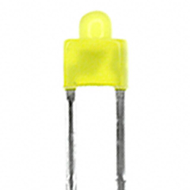
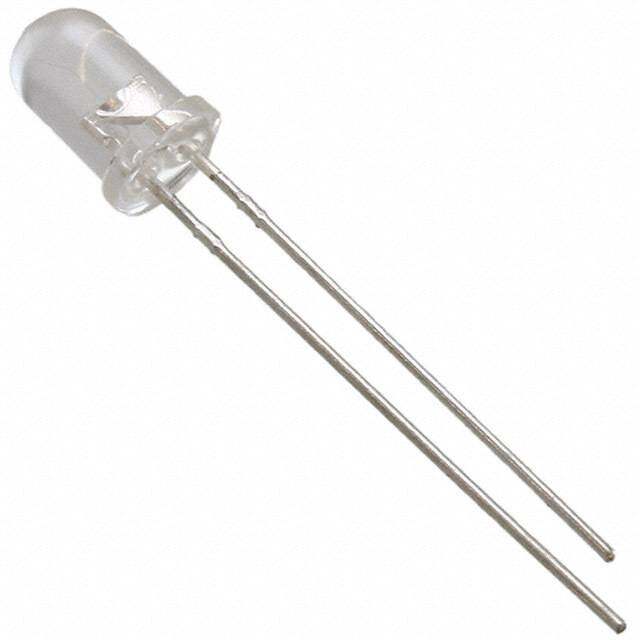
ICGOO电子元器件商城为您提供HLMP-3507由Avago Technologies设计生产,在icgoo商城现货销售,并且可以通过原厂、代理商等渠道进行代购。 HLMP-3507价格参考。Avago TechnologiesHLMP-3507封装/规格:LED 指示 - 分立, 绿色 569nm LED 指示 - 分立 2.1V 径向。您可以下载HLMP-3507参考资料、Datasheet数据手册功能说明书,资料中有HLMP-3507 详细功能的应用电路图电压和使用方法及教程。
Broadcom Limited的HLMP-3507是一款LED指示灯,属于分立元件类别。该型号的应用场景非常广泛,尤其适用于需要清晰可见、低功耗和长寿命指示灯的各种设备和系统中。以下是一些典型的应用场景:

1. 消费电子设备:
   - 用于电视、音响、投影仪等家电产品的电源指示、工作状态提示等。
   - 手机、平板电脑和其他便携式设备中的充电状态、网络连接等指示。

2. 工业控制系统:
   - 在自动化生产线、机器人控制系统中,用于显示设备运行状态、故障报警等信息。
   - 工业仪表、控制面板上的状态指示灯,帮助操作人员快速了解设备的工作情况。

3. 通信设备:
   - 网络交换机、路由器等网络设备中的端口状态、数据传输指示。
   - 基站、无线接入点等通信设施中的信号强度、连接状态指示。

4. 医疗设备:
   - 医疗仪器如心电图机、监护仪等设备中的工作状态、报警指示。
   - 输液泵、呼吸机等设备的状态指示,确保医护人员能及时获取设备信息。

5. 汽车电子:
   - 车内仪表盘上的各种指示灯,如油量、水温、故障报警等。
   - 车门未关、安全带未系等提醒指示灯,提高驾驶安全性。

6. 安防监控系统:
   - 摄像头、报警器等设备中的工作状态、报警指示。
   - 安防系统的控制面板上,用于显示系统状态、报警信息等。

7. 家用电器:
   - 微波炉、洗衣机、空调等家电产品中的工作模式、故障报警指示。
   - 吸尘器、空气净化器等设备中的电源、滤网更换等指示。

HLMP-3507具备高亮度、低功耗、长寿命的特点,能够在多种环境下稳定工作,因此在上述应用场景中表现出色,能够满足不同行业对可靠性和耐用性的要求。
| 参数 | 数值 |
| 产品目录 | |
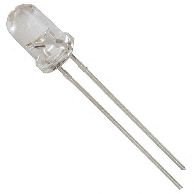
| 描述 | LED 5MM 565NM GREEN DIFF标准LED-通孔 Green Diffused 565nm 4.2mcd |
| 产品分类 | |
| LED大小 | T-1 3/4 |
| 品牌 | Avago Technologies |
| 产品手册 | http://www.avagotech.com/pages/en/leds/standard_brightness_through_hole_lamps/5mm_green/hlmp-3507/ |
| 产品图片 |
|
| rohs | 符合RoHS无铅 / 符合限制有害物质指令(RoHS)规范要求 |
| 产品系列 | LED发射器,标准LED-通孔,Avago Technologies HLMP-3507- |
| 数据手册 | http://www.avagotech.com/docs/AV02-1558EN |
| 产品型号 | HLMP-3507 |
| 产品目录绘图 |
|
| 产品目录页面 | |
| 产品种类 | 标准LED-通孔 |
| 光强度 | 4.2 mcd |
| 其它名称 | 516-1333 |
| 包装 | 散装 |
| 商标 | Avago Technologies |
| 大小/尺寸 | - |
| 安装类型 | 通孔 |
| 安装风格 | Through Hole |
| 封装 | Bulk |
| 封装/外壳 | 径向 |
| 工厂包装数量 | 2000 |
| 显示角 | 60 deg |
| 最大工作温度 | + 100 C |
| 最小工作温度 | - 20 C |
| 标准包装 | 2,000 |
| 正向电流 | 10 mA |
| 毫烛光等级 | 4.2mcd |
| 波长-主 | 569nm |
| 波长-峰值 | 565nm |
| 波长/色温 | 569 nm |
| 测试电流时的光通量 | - |
| 照明颜色 | Green |
| 电压-正向(Vf)(典型值) | 2.1V |
| 电流-测试 | 10mA |
| 相关产品 | /product-detail/zh/HLMP-5029/516-1395-ND/637656/product-detail/zh/HLMP-0103/516-1394-ND/637655 |
| 视角 | 60° |
| 透镜尺寸 | 5 mm |
| 透镜形状 | Dome |
| 透镜样式/尺寸 | 圆形,带圆顶,5mm,T-1 3/4 |
| 透镜类型 | 散射,有色 |
| 透镜颜色/类型 | Tinted, Diffused |
| 颜色 | 绿 |
| 高度 | 9.19mm |


- 商务部:美国ITC正式对集成电路等产品启动337调查
- 曝三星4nm工艺存在良率问题 高通将骁龙8 Gen1或转产台积电
- 太阳诱电将投资9.5亿元在常州建新厂生产MLCC 预计2023年完工
- 英特尔发布欧洲新工厂建设计划 深化IDM 2.0 战略
- 台积电先进制程称霸业界 有大客户加持明年业绩稳了
- 达到5530亿美元!SIA预计今年全球半导体销售额将创下新高
- 英特尔拟将自动驾驶子公司Mobileye上市 估值或超500亿美元
- 三星加码芯片和SET,合并消费电子和移动部门,撤换高东真等 CEO
- 三星电子宣布重大人事变动 还合并消费电子和移动部门
- 海关总署:前11个月进口集成电路产品价值2.52万亿元 增长14.8%

PDF Datasheet 数据手册内容提取
HLMP-3301, HLMP-3401, HLMP-3507, HLMP-3762, HLMP-3862, HLMP-3962, HLMP-D401 T-13/ (5 mm) Diffused LED Lamps 4 Data Sheet Description Features This family of T-13/4 tinted, diffused LED lamps is • High intensity widely used in general purpose indicator applica tions. • Choice of 4 bright colors Diffus ants, tints, and optical design are balanced to yield – High Efficiency Red superior light output and wide viewing angles. Several – Orange intensity choices are available in each color for increased – Yellow design flexibility. – High Performance Green • Popular T-13/4 diameter package Device Selection Guide • Selected minimum intensities Material/Color Part Number Luminous Intensity, • Wide viewing angle Iv (mcd) at 10mA • General purpose leads Min. Max. • Reliable and rugged GaP HER HLMP-3301 6.1 - • Available on tape and reel HLMP-3301-D00xx 2.4 - HLMP-3301-F00xx 6.1 - HLMP-3301-FG0xx 6.1 15.5 HLMP-3762 9.7 - HLMP-3762-G00xx 9.7 - GaP Yellow HLMP-3401 6.5 - HLMP-3401-E00xx 6.5 - HLMP-3862 10.3 - GaP Orange HLMP-D401 6.1 - HLMP-D401-EF0xx 3.8 9.7 GaP Green HLMP-3507 4.7 - HLMP-3507-D00xx 4.7 - HLMP-3507-EF0xx 7.6 19.1 HLMP-3962 12.0 - HLMP-3962-F00xx 12.0 -
Part Numbering System HLMP - x x xx - x x x xx Mechanical Option 00: Bulk 01: Tape & Reel, Crimped Leads 02: Tape & Reel, Straight Leads B1: Right Angle Housing, Uneven Leads B2: Right Angle Housing, Even Leads DD: Ammo Pack R4: Tape & Reel, Counter Clockwise Color Bin Options 0: Full Color Bin Distribution Maximum Iv Bin Options 0: Open (no max. limit) Others: Please refer to the Iv Bin Table Minimum Iv Bin Options Please refer to the Iv Bin Table Brightness Level 0x: Less Brightness 62: Higher Brightness Color Options 3,7: GaP HER 4,8: GaP Yellow (except D4xx) 5,9: GaP Green Package Options 3: T-1 3/4 (5 mm) D: T-1 3/4 (5 mm) GaP Orange Package Dimensions 0.89 (0.035) 6.10 (0.240) 0.64 (0.025) SQUARE TYP. 5.59 (0.220) 0.55 (0.022) 0.40 (0.016) 0.65 (0.026) max 5.08 (0.200) 4.57 (0.180) CATHODE LEAD 9.19 (0.362) 1.27(0.050) 2.54 (0.100) NOM. 8.43 (0.332) 25.40(1.00) NOM. MINIMUM Notes: 1. All dimensions are in mm (inches). 2. An epoxy meniscus may extend about 1 mm (0.040") down the leads. 3. For PCB hole recommendations, see the Precautions section. 2
Optical/Electrical Characteristics at T = 25°C A Test Symbol Parameter Color Min. Typ. Max. Units Condition 2q1/2 Included Angle High Efficiency Red 60 Deg. IF = 10 mA Between Half Orange 60 See Note 1 Luminous Intensity Yellow 60 Points Green 60 lPEAK Peak Wavelength High Efficiency Red 635 nm Measurement Orange 600 at Peak Yellow 583 Green 565 Dl1/2 Spectral Line Halfwidth HER/Orange 40 nm Yellow 36 Green 28 ld Dominant Wavelength High Efficiency Red 626 nm See Note 2 Orange 602 Yellow 585 Green 569 ts Speed of Response High Efficiency Red 90 ns Orange 280 Yellow 90 Green 500 C Capacitance High Efficiency Red 11 pF VF = 0; Orange 4 f = 1 MHz Yellow 15 Green 18 RqJ-PIN Thermal Resistance All 260 °C/W Junction to Cathode Lead VF Forward Voltage HER/Orange 1.9 2.4 V IF = 10 mA Yellow 2.0 2.4 Green 2.1 2.7 VR Reverse Breakdown All 5.0 V IR = 100 µA Voltage hV Luminous Efficacy High Efficiency Red – 145 lumens See Note 3 Orange 380 Watt Yellow – 500 Green 595 Notes: 1. q1/2 is the off-axis angle at which the luminous intensity is half the axial luminous intensity. 2. The dominant wavelength, ld, is derived from the CIE chromaticity diagram and represents the single wavelength which defines the color of the device. 3. Radiant intensity, Ie, in Watts/steradian, may be found from the equation Ie = Iv/hv, where Iv is the luminous intensity in candelas and hv is the luminous efficacy in lumens/Watt. 3
Absolute Maximum Ratings at T = 25°C A Green/ Parameter HER/Orange Yellow Emerald Green Units Peak Forward Current 90 60 90 mA Average Forward Current[1] 25 20 25 mA DC Current[2] 30 20 30 mA Power Dissipation[3] 135 85 135 mW Reverse Voltage (IR = 100 µA) 5 5 5 V Transient Forward Current[4] 500 500 500 mA (10 µsec Pulse) LED Junction Temperature 110 110 110 °C Operating Temperature Range -40 to +100 -40 to +100 -20 to +100 °C Storage Temperature Range -40 to +100 -40 to +100 -40 to +100 °C N otes: 1. See Figure 5 (Red/Orange), 10 (Yellow), or 15 (Green) to establish pulsed operating conditions. 2. For Red, Orange and Green series derate linearly from 50°C at 0.5 mA/°C. For Yellow series derate linearly from 50°C at 0.2 mA/°C. 3. 1.8 mW/°C. For Yellow series derate power linearly from 50°C at 1.6 mW/°C. 4. The transient peak current is the maximum non-recurring peak current that can be applied to the device without damaging the LED die and wirebond. It is not recommended that the device be operated at peak currents beyond the peak forward current listed in the Absolute Maxi- mum Ratings. 1.0 EMERALD GREEN ORANGE TA = 25 C Y SIT GREEN HIGH EFFICIENCY RED N E T E IN 0.5 V TI YELLOW A L E R 0 500 550 600 650 700 750 WAVELENGTH – nm Figure 1. Relative intensity vs. wavelength 4
T-13/ High Efficiency Red, Orange Diffused Lamps 4 Figure 2. Forward current vs. forward voltage Figure 3. Relative luminous intensity vs. Figure 4. Relative efficiency (luminous intensity per characteristics DC forward current unit current) vs. peak LED current Figure 5. Maximum tolerable peak current vs. Figure 6. Relative luminous intensity vs. angular displacement pulse duration. (IDC MAX as per MAX ratings) 5
T-13/ Yellow Diffused Lamps 4 Figure 7. Forward current vs. forward voltage Figure 8. Relative luminous intensity vs. Figure 9. Relative efficiency (luminous intensity per characteristics forward current unit current) vs. peak current Figure 10. Maximum tolerable peak current vs. Figure 11. Relative luminous intensity vs. angular displacement pulse duration. (IDC MAX as per MAX ratings) 6
T-13/ Green/Emerald Green Diffused Lamps 4 Figure 12. Forward current vs. forward voltage Figure 13. Relative luminous intensity vs. Figure 14. Relative efficiency (luminous intensity per characteristics DC forward current unit current) vs. peak LED current Figure 15. Maximum tolerable peak current vs. Figure 16. Relative luminous intensity vs. angular displacement pulse duration. (IDC MAX as per MAX ratings) 7
Intensity Bin Limits Intensity Range (mcd) Color Bin Min. Max. D 2.4 3.8 E 3.8 6.1 F 6.1 9.7 G 9.7 15.5 H 15.5 24.8 I 24.8 39.6 J 39.6 63.4 K 63.4 101.5 L 101.5 162.4 M 162.4 234.6 N 234.6 340.0 Red/Orange O 340.0 540.0 P 540.0 850.0 Q 850.0 1200.0 R 1200.0 1700.0 S 1700.0 2400.0 T 2400.0 3400.0 U 3400.0 4900.0 V 4900.0 7100.0 W 7100.0 10200.0 X 10200.0 14800.0 Y 14800.0 21400.0 Z 21400.0 30900.0 E 6.5 10.3 F 10.3 16.6 G 16.6 26.5 H 26.5 42.3 I 42.3 67.7 J 67.7 108.2 K 108.2 173.2 L 173.2 250.0 M 250.0 360.0 Yellow N 360.0 510.0 O 510.0 800.0 P 800.0 1250.0 Q 1250.0 1800.0 R 1800.0 2900.0 S 2900.0 4700.0 T 4700.0 7200.0 U 7200.0 11700.0 V 11700.0 18000.0 W 18000.0 27000.0 8
Intensity Bin Limits, continued Intensity Range (mcd) Color Bin Min. Max. D 4.7 7.6 E 7.6 12.0 F 12.0 19.1 G 19.1 30.7 H 30.7 49.1 I 49.1 78.5 J 78.5 125.7 K 125.7 201.1 L 201.1 289.0 Green M 289.0 417.0 N 417.0 680.0 O 680.0 1100.0 P 1100.0 1800.0 Q 1800.0 2700.0 R 2700.0 4300.0 S 4300.0 6800.0 T 6800.0 10800.0 U 10800.0 16000.0 V 16000.0 25000.0 W 25000.0 40000.0 Maximum tolerance for each bin limit is ±18%. Color Categories Lambda (nm) Color Category # Min. Max. 6 561.5 564.5 5 564.5 567.5 Green 4 567.5 570.5 3 570.5 573.5 2 573.5 576.5 1 582.0 584.5 3 584.5 587.0 Yellow 2 587.0 589.5 4 589.5 592.0 5 592.0 593.0 1 597.0 599.5 2 599.5 602.0 3 602.0 604.5 Orange 4 604.5 607.5 5 607.5 610.5 6 610.5 613.5 7 613.5 616.5 8 616.5 619.5 T olerance for each bin limit is ±0.5 nm. 9
Mechanical Option Matrix Mechanical Option Code Definition 00 Bulk Packaging, minimum increment 500 pcs/bag 01 Tape & Reel, crimped leads, minimum increment 1300 pcs/bag 02 Tape & Reel, straight leads, minimum increment 1300 pcs/bag B1 Right Angle Housing, uneven leads, minimum increment 500 pcs/bag B2 Right Angle Housing, even leads, minimum increment 500 pcs/bag DD Ammo Pack, straight leads with minimum increment 2K/pack R4 Tape & Reel, straight leads, counter clockwise, anode lead leaving the reel first Note: All categories are established for classification of products. Products may not be available in all categories. Please contact your local Avago repre- sentative for further clarification/information. 10
Precautions Lead Forming • The leads of an LED lamp may be preformed or cut to • Wave soldering parameter must be set and maintained length prior to insertion and soldering into PC board. according to recommended temperature and dwell time in the solder wave. Customer is advised to periodically • If lead forming is required before soldering, care must be check on the soldering profile to ensure the soldering taken to avoid any excessive mechanical stress induced profile used is always conforming to recommended to LED package. Otherwise, cut the leads of LED to length soldering condition. after soldering process at room temperature. The solder joint formed will absorb the mechanical stress of the • If necessary, use fixture to hold the LED component lead cutting from traveling to the LED chip die attach in proper orientation with respect to the PCB during and wirebond. soldering process. • It is recommended that tooling made to precisely form • Proper handling is imperative to avoid excessive thermal and cut the leads to length rather than rely upon hand stresses to LED components when heated. Therefore, operation. the soldered PCB must be allowed to cool to room temperature, 25°C, before handling. Soldering Conditions • Special attention must be given to board fabrication, • Care must be taken during PCB assembly and soldering solder masking, surface plating and lead holes size and process to prevent damage to LED component. component orientation to assure solderability. • The closest LED is allowed to solder on board is 1.59 mm below the body (encapsulant epoxy) for those parts • Recommended PC board plated through hole sizes for without standoff. LED component leads: • Recommended soldering conditions: LED Component Diagonal Plated Through- Lead Size Hole Diameter Manual Solder Lead size (typ.) 0.45 × 0.45 mm 0.636 mm 0.98 to 1.08 mm Wave Soldering Dipping (0.018 × 0.018 in.) (0.025 in) (0.039 to 0.043 in) Pre-heat Temperature 105 °C Max. – Dambar shear- 0.65 mm 0.919 mm Pre-heat Time 30 sec Max. – off area (max.) (0.026 in) (0.036 in) Peak Temperature 250 °C Max. 260 °C Max. Lead size (typ.) 0.50 × 0.50 mm 0.707 mm 1.05 to 1.15 mm (0.020 × 0.020 in.) (0.028 in) (0.041 to 0.045 in) Dwell Time 3 sec Max. 5 sec Max. Dambar shear- 0.70 mm 0.99 mm off area (max.) (0.028 in) (0.039 in) Note: Refer to application note AN1027 for more information on soldering LED components. TURBULENT WAVE LAMINAR WAVE BOTTOM SIDE 250 HOT AIR KNIFE OF PC BOARD TOP SIDE OF PC BOARD C 200 – E R CONVEYOR SPEED = 1.83 M/MIN (6 FT/MIN) U 150 PREHEAT SETTING = 150C (100C PCB) T A SOLDER WAVE TEMPERATURE = 245C ER FLUXING AIR KNIFE AIR TEMPERATURE = 390C P AIR KNIFE DISTANCE = 1.91 mm (0.25 IN.) M 100 AIR KNIFE ANGLE = 40 E T SOLDER: SN63; FLUX: RMA 50 NOTE: ALLOW FOR BOARDS TO BE 30 SUFFICIENTLY COOLED BEFORE EXERTING PREHEAT MECHANICAL FORCE. 0 10 20 30 40 50 60 70 80 90 100 TIME – SECONDS Figure 17. Recommended wave soldering profile For product information and a complete list of distributors, please go to our website: www.avagotech.com Avago, Avago Technologies, and the A logo are trademarks of Avago Technologies in the United States and other countries. Data subject to change. Copyright © 2005-2015 Avago Technologies. All rights reserved. Obsoletes 5989-4258EN AV02-1558EN - March 30, 2015
Mouser Electronics Authorized Distributor Click to View Pricing, Inventory, Delivery & Lifecycle Information: B roadcom Limited: HLMP-3301 HLMP-3301-D0000 HLMP-3301-D0001 HLMP-3301-D0002 HLMP-3301-D00B2 HLMP-3301-F0001 HLMP-3301-F0002 HLMP-3301-F00B2 HLMP-3301-F00DD HLMP-3301-FG000 HLMP-3401 HLMP-3401-E0002 HLMP-3401-E00B2 HLMP-3507 HLMP-3507-D0001 HLMP-3507-D0002 HLMP-3507-D00B1 HLMP-3507-D00B2 HLMP-3507-EF000 HLMP-3762 HLMP-3762-G00B2 HLMP-3862 HLMP-3962 HLMP-3962-F0002 HLMP-3962- F00B2 HLMP-D401 HLMP-D401-EF0FH