ICGOO在线商城 > GTC06G-24-10SW

 Datasheet下载
- 型号: GTC06G-24-10SW
- 制造商: Amphenol
- 库位|库存: xxxx|xxxx
- 要求:
| 数量阶梯 | 香港交货 | 国内含税 |
| +xxxx | $xxxx | ¥xxxx |
查看当月历史价格
查看今年历史价格
GTC06G-24-10SW产品简介:
ICGOO电子元器件商城为您提供GTC06G-24-10SW由Amphenol设计生产,在icgoo商城现货销售,并且可以通过原厂、代理商等渠道进行代购。 提供GTC06G-24-10SW价格参考以及AmphenolGTC06G-24-10SW封装/规格参数等产品信息。 你可以下载GTC06G-24-10SW参考资料、Datasheet数据手册功能说明书, 资料中有GTC06G-24-10SW详细功能的应用电路图电压和使用方法及教程。
| 参数 | 数值 |
| 产品目录 | |
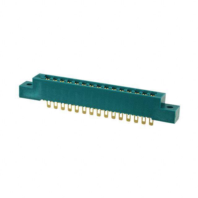
| 描述 | CONN PLUG 7POS INLINE SKT |
| 产品分类 | |
| 品牌 | Amphenol Industrial Operations |
| 数据手册 | |
| 产品图片 | |
| 产品型号 | GTC06G-24-10SW |
| rohs | 含铅 / 不符合限制有害物质指令(RoHS)规范要求 |
| 产品系列 | GT,MIL-5015 衍生 |
| 侵入防护 | IP67 - 防尘,防水 |
| 其它名称 | AGTC06G-24-10SW |
| 包装 | 散装 |
| 外壳尺寸-插件 | 24-10 |
| 外壳尺寸,MIL | - |
| 外壳材料,镀层 | 铝,镀草绿色镉 |
| 安装类型 | 自由悬挂 |
| 工作温度 | -55°C ~ 125°C |
| 朝向 | W |
| 标准包装 | 1 |
| 特性 | 收缩套适配器 |
| 电压-额定 | 500VAC,700VDC |
| 端接 | 压接 |
| 紧固类型 | 反向插销锁 |
| 触头镀层 | 银 |
| 触头镀层厚度 | - |
| 连接器类型 | 插头,母型插口 |
| 针脚数 | 7 |
| 额定电流 | - |


- 商务部:美国ITC正式对集成电路等产品启动337调查
- 曝三星4nm工艺存在良率问题 高通将骁龙8 Gen1或转产台积电
- 太阳诱电将投资9.5亿元在常州建新厂生产MLCC 预计2023年完工
- 英特尔发布欧洲新工厂建设计划 深化IDM 2.0 战略
- 台积电先进制程称霸业界 有大客户加持明年业绩稳了
- 达到5530亿美元!SIA预计今年全球半导体销售额将创下新高
- 英特尔拟将自动驾驶子公司Mobileye上市 估值或超500亿美元
- 三星加码芯片和SET,合并消费电子和移动部门,撤换高东真等 CEO
- 三星电子宣布重大人事变动 还合并消费电子和移动部门
- 海关总署:前11个月进口集成电路产品价值2.52万亿元 增长14.8%


PDF Datasheet 数据手册内容提取
Amphenol ® GT Series Reverse Bayonet Coupling Connectors 12-024-8 Ruggedized Connector Series for Rail/Mass Transit and other Harsh Environments AMPHENOL CORPORATION Amphenol Industrial Operations 40-60 Delaware Avenue Sidney, New York 13838-1395 Phone: 800-678-0141 or 607-563-5011 www.amphenol-industrial.com Amphenol
Table of Contents Page No. Amphenol® GT Series Reversed Bayonet Coupling Connectors General Description - - - - - - - - - - - - - - - - - - - - - - - - - - - - - - - - - - - - - - - - - - - - - - - - - - - - - - - - - - - - - - - - - - -1 GT Series insert availability charts - - - - - - - - - - - - - - - - - - - - - - - - - - - - - - - - - - - - - - - - - - - - - - - - - - - - - - - 2-4 GT Series insert alternate positioning- - - - - - - - - - - - - - - - - - - - - - - - - - - - - - - - - - - - - - - - - - - - - - - - - - - - - - -5 GT Series contact arrangements - - - - - - - - - - - - - - - - - - - - - - - - - - - - - - - - - - - - - - - - - - - - - - - - - - - - - - - 6-28 GT Connector Classes - - - - - - - - - - - - - - - - - - - - - - - - - - - - - - - - - - - - - - - - - - - - - - - - - - - - - - - - - - - - - - - -29 GT00A wall mount receptacle for front panel mounting - - - - - - - - - - - - - - - - - - - - - - - - - - - - - - - - - - - - -30 GT00AF/00F wall mount receptacle for front panel mounting- - - - - - - - - - - - - - - - - - - - - - - - - - - - - - - - -31 GT00CF/00CFZ wall mount receptacle for front panel mounting- - - - - - - - - - - - - - - - - - - - - - - - - - - - - - -32 GT00G wall mount receptacle for front panel mounting - - - - - - - - - - - - - - - - - - - - - - - - - - - - - - - - - - - - -33 GT00LCF/00LCFZ wall mount receptacle for front panel mounting- - - - - - - - - - - - - - - - - - - - - - - - - - - - -34 GT00R wall mount receptacle for front panel mounting - - - - - - - - - - - - - - - - - - - - - - - - - - - - - - - - - - - - -35 GT00RV wall mount receptacle for front panel mounting - - - - - - - - - - - - - - - - - - - - - - - - - - - - - - - - - - - -36 GT01A inline receptacle- - - - - - - - - - - - - - - - - - - - - - - - - - - - - - - - - - - - - - - - - - - - - - - - - - - - - - - - - - -37 GT01AF/01F inline receptacle- - - - - - - - - - - - - - - - - - - - - - - - - - - - - - - - - - - - - - - - - - - - - - - - - - - - - - -38 GT01G inline receptacle- - - - - - - - - - - - - - - - - - - - - - - - - - - - - - - - - - - - - - - - - - - - - - - - - - - - - - - - - - -39 GT01LCF/01LCFZ inline receptacle - - - - - - - - - - - - - - - - - - - - - - - - - - - - - - - - - - - - - - - - - - - - - - - - - -40 GT01R inline receptacle- - - - - - - - - - - - - - - - - - - - - - - - - - - - - - - - - - - - - - - - - - - - - - - - - - - - - - - - - - -41 GT01RV inline receptacle- - - - - - - - - - - - - - - - - - - - - - - - - - - - - - - - - - - - - - - - - - - - - - - - - - - - - - - - - -42 GT02R/02RFS box mount receptacle for front panel mounting- - - - - - - - - - - - - - - - - - - - - - - - - - - - - - - -43 GT020R/020RFSM box mount receptacle for front panel mounting- - - - - - - - - - - - - - - - - - - - - - - - - - - - -44 GT030 square flange receptacle for rear panel mounting- - - - - - - - - - - - - - - - - - - - - - - - - - - - - - - - - - - -45 GT030A square flange receptacle for rear panel mounting- - - - - - - - - - - - - - - - - - - - - - - - - - - - - - - - - - -46 GT030AF/030F square flange receptacle for rear panel mounting - - - - - - - - - - - - - - - - - - - - - - - - - - - - -47 GT030G square flange receptacle for rear panel mounting - - - - - - - - - - - - - - - - - - - - - - - - - - - - - - - - - -48 GT030LCF/030LCFZ square flange receptacle for rear panel mounting - - - - - - - - - - - - - - - - - - - - - - - - -49 GT030R square flange receptacle for rear panel mounting - - - - - - - - - - - - - - - - - - - - - - - - - - - - - - - - - -50 GT030RV square flange receptacle for rear panel mounting - - - - - - - - - - - - - - - - - - - - - - - - - - - - - - - - -51 GT06A straight plug- - - - - - - - - - - - - - - - - - - - - - - - - - - - - - - - - - - - - - - - - - - - - - - - - - - - - - - - - - - - - -52 GT06AF/06F straight plug- - - - - - - - - - - - - - - - - - - - - - - - - - - - - - - - - - - - - - - - - - - - - - - - - - - - - - - - - -53 GT06CF straight plug- - - - - - - - - - - - - - - - - - - - - - - - - - - - - - - - - - - - - - - - - - - - - - - - - - - - - - - - - - - - -54 GT06CFGG straight plug - - - - - - - - - - - - - - - - - - - - - - - - - - - - - - - - - - - - - - - - - - - - - - - - - - - - - - - - - -55 GT06G straight plug- - - - - - - - - - - - - - - - - - - - - - - - - - - - - - - - - - - - - - - - - - - - - - - - - - - - - - - - - - - - - -56 GT06G2 straight plug- - - - - - - - - - - - - - - - - - - - - - - - - - - - - - - - - - - - - - - - - - - - - - - - - - - - - - - - - - - - -57 GT06LC straight plug- - - - - - - - - - - - - - - - - - - - - - - - - - - - - - - - - - - - - - - - - - - - - - - - - - - - - - - - - - - - -58 GT06LCF/06LCFZ straight plug - - - - - - - - - - - - - - - - - - - - - - - - - - - - - - - - - - - - - - - - - - - - - - - - - - - - -59 GT06LT straight plug - - - - - - - - - - - - - - - - - - - - - - - - - - - - - - - - - - - - - - - - - - - - - - - - - - - - - - - - - - - - -60 GT06PFC straight plug- - - - - - - - - - - - - - - - - - - - - - - - - - - - - - - - - - - - - - - - - - - - - - - - - - - - - - - - - - - -61 GT06PG straight plug- - - - - - - - - - - - - - - - - - - - - - - - - - - - - - - - - - - - - - - - - - - - - - - - - - - - - - - - - - - - -62 GT06PP/064PP panel plug- - - - - - - - - - - - - - - - - - - - - - - - - - - - - - - - - - - - - - - - - - - - - - - - - - - - - - - - -63 GT06R straight plug- - - - - - - - - - - - - - - - - - - - - - - - - - - - - - - - - - - - - - - - - - - - - - - - - - - - - - - - - - - - - -64 GT06RV straight plug- - - - - - - - - - - - - - - - - - - - - - - - - - - - - - - - - - - - - - - - - - - - - - - - - - - - - - - - - - - - -65 GT06SB straight plug- - - - - - - - - - - - - - - - - - - - - - - - - - - - - - - - - - - - - - - - - - - - - - - - - - - - - - - - - - - - -66 GT06SBT straight plug- - - - - - - - - - - - - - - - - - - - - - - - - - - - - - - - - - - - - - - - - - - - - - - - - - - - - - - - - - - -67 GT065SL straight plug - - - - - - - - - - - - - - - - - - - - - - - - - - - - - - - - - - - - - - - - - - - - - - - - - - - - - - - - - - - -68 GT07R jam nut receptacle - - - - - - - - - - - - - - - - - - - - - - - - - - - - - - - - - - - - - - - - - - - - - - - - - - - - - - - - -69 GT070 jam nut receptacle- - - - - - - - - - - - - - - - - - - - - - - - - - - - - - - - - - - - - - - - - - - - - - - - - - - - - - - - - -70 GT08A 90° angle plug - - - - - - - - - - - - - - - - - - - - - - - - - - - - - - - - - - - - - - - - - - - - - - - - - - - - - - - - - - - -71 GT08AF/08F 90° angle plug- - - - - - - - - - - - - - - - - - - - - - - - - - - - - - - - - - - - - - - - - - - - - - - - - - - - - - - -72 GT08CFGG 90° angle plug- - - - - - - - - - - - - - - - - - - - - - - - - - - - - - - - - - - - - - - - - - - - - - - - - - - - - - - - -73 GT08LT 90° angle plug- - - - - - - - - - - - - - - - - - - - - - - - - - - - - - - - - - - - - - - - - - - - - - - - - - - - - - - - - - - -74 GT08PFC 90° angle plug - - - - - - - - - - - - - - - - - - - - - - - - - - - - - - - - - - - - - - - - - - - - - - - - - - - - - - - - - -75 GT08R 90° angle plug - - - - - - - - - - - - - - - - - - - - - - - - - - - - - - - - - - - - - - - - - - - - - - - - - - - - - - - - - - - -76 GT05 dummy receptacle - - - - - - - - - - - - - - - - - - - - - - - - - - - - - - - - - - - - - - - - - - - - - - - - - - - - - - - - - -77 GTTB thru-bulkhead receptacles- - - - - - - - - - - - - - - - - - - - - - - - - - - - - - - - - - - - - - - - - - - - - - - - - - - - -78 Sealing gaskets - - - - - - - - - - - - - - - - - - - - - - - - - - - - - - - - - - - - - - - - - - - - - - - - - - - - - - - - - - - - - - - - - - - - -79 Receptacle protection caps - - - - - - - - - - - - - - - - - - - - - - - - - - - - - - - - - - - - - - - - - - - - - - - - - - - - - - - - - - - - -80 Plug protection caps - - - - - - - - - - - - - - - - - - - - - - - - - - - - - - - - - - - - - - - - - - - - - - - - - - - - - - - - - - - - - - - - - -81 MS3057-A cable clamp - - - - - - - - - - - - - - - - - - - - - - - - - - - - - - - - - - - - - - - - - - - - - - - - - - - - - - - - - - - - - - - -82 MS3420 bushing- - - - - - - - - - - - - - - - - - - - - - - - - - - - - - - - - - - - - - - - - - - - - - - - - - - - - - - - - - - - - - - - - - - - -83 MS3057-C style (10-350349) cable clamp- - - - - - - - - - - - - - - - - - - - - - - - - - - - - - - - - - - - - - - - - - - - - - - - - - -84 Rear mounting data - receptacles, sealing plugs, sealing ranges- - - - - - - - - - - - - - - - - - - - - - - - - - - - - - - - - - -85 Crimp and solder contact information - - - - - - - - - - - - - - - - - - - - - - - - - - - - - - - - - - - - - - - - - - - - - - - - - - - 86, 87 HOW TO ORDER, connector intermateability - - - - - - - - - - - - - - - - - - - - - - - - - - - - - - - - - - - - - - - - - - - - - - - -88 GT Amphe-Power Connectors with RADSOK® Technology, Amphe-Power™ Amphe-GTR, Power GT - - - - - - - - - - - - - - - - - - - - - - - - - - - - - - - - - - - - - - - - - - - - - - -89 Special Application GT Connectors: GTC-M Series with metal clips, GT-PC Connectors for high voltage power applications, GT Connectors for the HMI Lighting industry - - - - - - - - - - - - - - - - - - - - - - - - - - - - - - - - - - - - - - - - - - - -90 Additional Amphenol Industrial Products for the Rail Industry - - - - - - - - - - - - - - - - - - - - - - - - - - - - - - - - - - 91, 92 Sales office listing Amphenol Aerospace operates quality systems that are certified to ISO9001: 2000 by third party registrars.
Amphenol® GT Connectors with reverse bayonet coupling the preferred connector for mass transit Designed originally for use by the military, the heavy duty GT connector has become widely used in commercial, geophysical, aerospace, ground support and shipboard applications. It is the preferred connector for mass transit. Variety of Shell Styles are Available Amphenol® GT reverse bayonet coupling connectors with MIL-C-5015 insert patterns features: Wall Mount Receptacle (cid:127) Quick positive coupling (cid:127) Audible, tactile and visual indication of full coupling (cid:127) Waterproof – IP67 rated (cid:127) No lockwiring required (cid:127) High shock and vibration capabilities (cid:127) Inserts available in Neoprene and Viton* materials (cid:127) Low smoke/flame retardant inserts also available Inline Receptacle (cid:127) Operating temperature range: With Neoprene inserts: –55°C to +125°C With Viton** inserts: –50°C to +200°C With low smoke/flame retardant inserts: –55°C to +125°C (cid:127) Available in both crimp and solder terminations (cid:127) Contacts available in gold and silver plating (cid:127) Numerous military and commercial finishes available (cid:127) Zinc alloy plating (cadmium free) available Straight Plug (cid:127) Rugged construction; aluminum or stainless steel components (cid:127) Available with resilient cover coupling for added damage protection and increased gripping surface (cid:127) Intermateable with existing VG95234 connectors (cid:127) 2000 couplings minimum (cid:127) UL recognized (cid:127) Up to 50% more ampacity with the use of RADSOK ® Plug With Rubber Covered technology (see page 89) Coupling Nut Amphenol’s special offerings of GT Series connectors (see end of catalog) include: GT Amphe-Power® Connectors with RADSOK® technology, the GTC-M Series with metal clip inserts and GT-PC Series for high voltage power applica- tions. There is also information on other Amphenol Industrial Products for the Rail Industry at the end of this catalog. For further information on your individual application require- ments, contact: Jam Nut Receptacle Amphenol Corporation Amphenol Industrial Operations 40-60 Delaware Avenue Sidney, New York 13838-1395 Phone: 607-563-5011 Fax: 607-563-5351 NOTE: The connector products in this brochure were formerly known as www.amphenol-industrial.com Bendix® products. These products are now manufactured and sold under the Amphenol® brand name. The name “Amphenol” will 1 **For availability of Viton inserts consult Amphenol, Sidney, NY. replace the name “Bendix” on products and literature in the future. Viton is a registered trademark of Dupont/Dow Corning.
GT Series insert availability Contact Size Contact Size Insert Total Insert Total Arrange- Service Con- Coax Arrange- Service Con- Coax ment Rating tacts 0 4 8 12 16 0 4 8 12 ment Rating tacts 0 4 8 12 16 0 4 8 12 10SL-3 A 3 3 20-2 D 1 1 10SL-4† A 2 2 20-3 D 3 3 14S-2 Inst. 4 4 20-4 D 4 4 14S-4 D 1 1 20-6 D 3 3 14S-5 Inst. 5 5 20-7 D/A 8 8 14S-6 Inst. 6 6 20-8 Inst. 6 2 4 14S-7 A 3 3 20-9 D/A 8 1 7 14S-9 A 2 2 20-11 Inst. 13 13 14S-10 Inst. 4 4 20-12 A 2 1 1 14S-12 A 3 3 20-14 A 5 2 3 14S-A7 A 7 7 20-15 A 7 7 16S-1 A 7 7 20-16 A 9 2 7 16S-3 B 1 1 20-17 A 6 5 1 16S-4 D 2 2 20-18 A 9 3 6 16S-5 A 3 3 20-19 A 3 3 16S-6 A 3 3 20-20 A 4 1 3 16S-8 A 5 5 20-21 A 9 1 8 16-2 E 1 1 20-22 A 6 3 3 16-7 A 3 1 2 20-23 A 2 2 16-9 A 4 2 2 20-24 A 4 2 2 16-10 A 3 3 20-25 Inst. 13 13 16-11 A 2 2 20-26 A 19 19 16-12 A 1 1 20-27 A 14 14 16-13 A 2 2 20-29 A 17 17 16-59 A 4 4 20-30 Inst. 13 13 18-1 A/Inst. 10 10 20-33 A 11 11 18-3 D 2 2 20-51 A 3 3 18-4 D 4 4 20-57 A 7 7* 18-5 D 3 2 1 20-58 A 10 5 5 18-6 D 1 1 20-59 A 3 3* 18-7 B 1 1 20-66 A 6 5* 1 18-8 A 8 1 7 20-79 A/D 8 1 7 18-9 Inst. 7 2 5 22-1 D 2 2 18-10 A 4 4 22-2 D 3 3 18-11 A 5 5 22-4 A 4 2 2 18-12 A 6 6 22-5 D 6 2 4 18-13 A 4 1 3 22-6 D 3 2 1 18-14 A 2 1 1 22-7 E 1 1 18-15 A 4 4 22-8 E 2 2 18-16 C 1 1 22-9 E 3 3 18-17 Inst. 7 2 5 22-10 E 4 4 18-19 A 10 10 22-11 B 2 2 18-20 A 5 5 22-12 D 5 2 3 18-22 D 3 3 22-13 D/A 5 4 1 18-24 A/Inst. 10 10 22-14 A 19 19 18-29 A 5 5 22-15 E/A 6 5 1 18-30 A 5 5 †10SL-4 arrangement available only with pin contacts in receptacle and socket 18-31 A 5 5 contacts in plug *Crimp contacts accommodate wire the same size as the contact as well as wire of **Coaxial cable data can be found on insert arrangement drawings, pages 6-28. the next smaller, even size. Arrangements identified with an asterisk (*) are excep- For further information on coaxial contacts and cable see catalog 12-130. tions. See insert arrangement drawings on pages 6-28 for application wire size. 2
GT Series insert availability, cont. Contact Size Contact Size Insert Total Insert Total Arrange Service Con- Coax** Arrange Service Con- Coax** ment Rating tacts 0 4 8 12 16 0 4 8 12 ment Rating tacts 0 4 8 12 16 0 4 8 12 22-16 A 9 3 6 24-84 A 19 1 18 22-17 D/A 9 1 8 24-96 Inst. 28 28 22-18 D/A 8 8 24-AJ A 25 25 22-19 A 14 14 28-1 D/A 9 3 6 22-20 A 9 9 28-2 D 14 2 12 22-21 A 3 1 2 28-3 E 3 3 22-22 A 4 4 28-4 E/D 9 2 7 22-23 D/A 8 8 28-5 D 5 2 1 2 22-24 D/A 6 2 4 28-6 D 3 3 22-27 D/A 9 1 8 28-7 D 2 2 22-28 A 7 7 28-8 E/D/A 12 2 10 22-33 D/A 7 7 28-9 D 12 6 6 22-34 D 5 3 2 28-10 D/A 7 2 2 3 22-63 A 12 4 8 28-11 A 22 4 18 22-65 D/A 8 8* 28-12 A 26 26 22-70 A 13 8 5 28-13 A 26 26 22-80 A 3 3* 28-15 A 35 35 24-2 D 7 7 28-16 A 20 20 24-3 D 7 2 5 28-17 B/D/A 15 15 24-5 A 16 16 28-18 C/D/A/Inst. 12 12 24-6 D/A 8 8 28-19 B/D/A 10 4 6 24-7 A 16 2 14 28-20 A 14 10 4 24-9 A 2 2 28-21 A 37 37 24-10 A 7 7 28-22 D 6 3 3 24-11 A 9 3 6 28-51 A 12 12 24-12 A 5 2 3 28-59 A 17 7 10 24-16 D/A 7 1 3 3 28-66 A 16 2 14 24-17 D 5 2 3 28-72 Coax 3 3 24-19 A 12 12 28-74 A 16 7* 9 24-20 D 11 2 9 28-75 A 16 7* 9 24-21 D 10 1 9 28-79 A 16 7 9 24-22 D 4 4 28-82 D 6 2 4 24-27 E 7 7 28-84 A 9 9 24-28 Inst. 24 24 28-AY A 9 4 5 24-51 A 5 5 32-1 E/D 5 2 3 24-52 Hi Volt. 1 1 32-2 E 5 3 2 24-53 A 5 5 32-3 D 9 1 2 2 4 24-58 A 13 3 3 7 32-4 A/D 14 2 12 24-59 A 14 7 7 32-5 D 2 2 24-60 A 7 7* 32-6 A 23 2 3 2 16 24-65 A 15 11 4 32-7 Inst./A 35 7 28 24-66 D 7 7 32-8 A 30 6 24 24-67 Inst. 19 19 32-9 D 14 2 12 24-71 A 7 7* 32-10 E/B/D/A 7 2 2 3 24-75 A 7 7* 32-12 A/D 15 5 10 24-79 A 5 5 32-13 D 23 5 18 24-80 Inst. 23 23 32-15 D 8 2 6 32-16 A 23 2 3 2 16 *Crimp contacts accommodate wire the same size as the contact as well as wire of the next smaller, even size. Arrangements identified with an asterisk (*) are excep- **Coaxial cable data can be found on insert arrangement drawings, pages 6-28. tions. See insert arrangement drawings on pages 6-28 for application wire size. For further information on coaxial contacts and cable see catalog 12-130. 3
GT Series insert availability, cont. Contact Size Contact Size Insert Total Insert Total Arrange- Service Con- Coax** Arrange- Service Con- Coax** ment Rating tacts 0 4 8 12 16 0 4 8 12 ment Rating tacts 0 4 8 12 16 0 4 8 12 32-17 D 4 4 36-71 A 53 3 50 32-22 A 54 54 36-73 Coax 7 7 32-25 A 25 25 36-74 A 44 43 1 32-31 A 31 31 36-75 A 48 48* 32-48 Inst. 48 48 36-76 A 47 47 32-52 D 8 2 6 36-77 D 7 7 32-53 E/Inst. 42 5 37 36-78 A 14 12 2 32-56 A 30 6* 24 36-79 A 20 20 32-57 Coax 8 6 2 36-80 A 20 20* 32-58 Coax 4 4 36-83 Coax 7 7 32-59 A 42 40 2 36-85 A/D 35 35* 32-60 A 23 15 8 36-97 C 1 1 size 4/0 32-62 Coax 23 2 1 2 16 2 36-99 D 12 3 3 3 3 32-64 Inst. 54 54 36-AF A 48 48 32-68 A 16 12 4 40-1 D 30 6 24 32-73 A 46 46 40-5 A 5 5 32-75 Coax 9 2 7 40-9 A 47 1 22 24 32-76 A 19 19 40-10 A 29 4 9 16 32-79 D 5 4 1 40-30 A 30 1 29 32-82 A 16 4 12 40-35 D 35 35 32-AF A 55 55 40-53 A 60 60 32-AM A 1 1 size 4/0 40-56 A 85 85 36-1 D 22 4 18 40-57 E 4 4 36-3 D 6 3 3 40-61 A 59 1 3 55 36-4 D/A 3 3 40-62 A 60 60 36-5 A 4 4 40-63 A 61 61* 36-6 A 6 2 4 40-64 Coax 36 3 20 13 36-7 A 47 7 40 40-66 Coax 4 4 36-8 A 47 1 46 40-67 A 11 1 10 36-9 A 31 1 2 14 14 40-68 A 21 21 36-10 A 48 48 40-70 A 61 61 36-11 A 48 48 40-72 A 11 1 10 36-12 A 48 48 40-73 A 61 61 36-13 E/A 17 2 15 40-74 A 6 1 4 1 36-14 D 16 5 5 6 40-75 E 5 4 1 36-15 D/A 35 35 40-80 A 11 10 1 36-16 A 47 7 40 40-81 A 62 62* 36-17 A 47 7 40 40-82 A 62 62 36-18 A 31 1 2 14 14 40-85 A 60 60* 36-20 A 34 2 2 30 40-86 Coax 4 4 36-22 D 22 22 40-87 D 7 7 36-51 D 4 2 2 40-AD A 8 4 4 36-52 A 52 52 40-AG A 38 38 36-54 A 39 8 31 40-AP E 2 2 size 4/0 36-55 A 39 8* 31 40-AR Inst. 13 3 3 7 36-59 A 53 3* 50 40-AS A 40 25 15 36-60 A 47 7* 40 40-AT A 43 1 24 18 36-64 Coax 4 4 40-AU A 14 3 10 1 36-65 Coax 4 4 40-AV D 3 3 size 2/0 *Crimp contacts accommodate wire the same size as the contact as well as **Coaxial cable data can be found on insert arrangement drawings, pages 6-28. wire of the next smaller, even size. Arrangements identified with an asterisk (*) For further information on coaxial contacts and cable see catalog 12-130. are exceptions. See insert arrangement drawings on pages 6-28 for applica- 4 tion wire size.
GT Series insert alternate positioning To avoid cross-plugging problems in applications requir- The following insert arrangements have the same alter- ing the use of more than one connector of the same size nate insert rotations for W, X, Y and Z, which are: and arrangement, alternate rotations are available as indicated in the accompanying charts. Degrees W X Y Z As shown in the diagram below, the front face of the pin 80 110 250 280 insert is rotated within the shell in a clockwise direction from the normal shell key. The socket insert would be T rotated counter-clockwise the same number of degrees 16-7 20-16 22-18 24-4 24-28 28-16 32-10 in respect to the normal shell key. 18-5 20-20 22-19 24-5 24-AJ 28-17 32-12 18-9 20-22 22-21 24-6 28-1 28-19 32-13 18-13 22-3 22-24 24-7 28-4 28-20 32-22 18-14 22-6 22-25 24-12 28-8 28-21 32-AF A A B B 20-7 22-12 22-29 24-14 28-9 32-1 36-1 B B A A 20-8 22-14 22-33 24-16 28-10 32-3 36-7 20-9 22-15 22-34 24-17 28-11 32-4 36-8 Position W Position X Position Y Position Z 20-12 22-16 24-1 24-20 28-14 32-6 36-13 20-14 22-17 24-3 24-21 28-15 32-9 40-53 View looking into front face of pin insert or rear of socket insert. Insert Degrees Insert Degrees Insert Degrees Arrangement W X Y Z Arrangement W X Y Z Arrangement W X Y Z 10SL-4 63 – – – 20-19 90 180 270 – 28-7 35 110 250 325 14S-2 – 120 240 – 20-21 35 110 250 325 28-12 90 180 270 – 14S-5 – 110 – – 20-23 35 110 250 325 28-18 70 145 215 290 14S-7 90 180 270 – 20-24 35 110 250 325 28-22 70 145 215 290 14S-9 70 145 215 290 20-27 35 110 250 325 28-AY 45 110 250 – 16-9 35 110 250 325 20-29 80 – – 280 32-2 70 145 215 290 16-10 90 180 270 – 20-33 – – – 280 32-5 35 110 250 325 16-11 35 110 250 325 22-1 35 110 250 325 32-7 80 125 235 280 16-13 35 110 250 325 22-2 70 145 215 290 32-8 80 125 235 280 16S-1 80 – – 280 22-4 35 110 250 325 32-15 35 110 250 280 16S-4 35 110 250 325 22-5 35 110 250 325 32-17 45 110 250 – 16S-5 70 145 215 290 22-8 35 110 250 325 32-25 60 120 – – 16S-6 90 180 270 – 22-9 70 145 215 290 32-64* 80 100 110 250 16S-8 – 170 265 – 22-10 35 110 250 325 32-68 30 – – – 18-1 70 145 215 290 22-11 35 110 250 325 32-82 30 – – – 18-3 35 110 250 325 22-13 35 110 250 325 36-3 70 145 215 290 18-4 35 110 250 325 22-20 35 110 250 325 36-4 70 145 215 290 18-8 70 – – 290 22-22 – 110 250 – 36-5 – 120 240 – 18-10 – 120 240 – 22-23 35 – 250 – 36-6 35 110 250 325 18-11 – 170 265 – 22-27 80 – 250 280 36-9 80 125 235 280 18-12 80 – – 280 22-28 80 – – 280 36-10 80 125 235 280 18-15 – 120 240 – 24-2 80 – – 280 36-14 90 180 270 – 18-20 90 180 270 – 24-9 35 110 250 325 36-15 60 125 245 305 18-22 70 145 215 290 24-10 80 – – 280 36-AF 65 – – – 18-29 90 180 270 – 24-11 35 110 250 325 40-1 65 130 235 300 20-3 70 145 215 290 24-22 45 110 250 – 40-5 33 – – 270 20-4 45 110 250 – 24-27 80 – – 280 40-9 65 125 225 310 20-5 35 110 250 325 24-96 65 – – – 40-10 65 125 225 310 20-6 70 145 215 290 28-2 35 110 250 325 40-35 70 130 230 290 20-15 80 – – 280 28-3 70 145 215 290 40-56 72 144 216 288 20-17 90 180 270 – 28-5 35 110 250 325 40-AG 37 74 285 322 20-18 35 110 250 325 28-6 70 145 215 290 *Additional rotations available; consult Amphenol for information. 5
GT Series contact arrangements front face of pin insert or rear face of socket insert illustrated B A D A E A A BC C B D B C Front of Front of Socket Insert Socket Insert Insert Arrangement 10SL-3 10SL-4 14S-2 14S-4 14S-5 Service Rating A A Inst. D Inst. Number of Contacts 3 2 4 1 5 Contact Size 16 16 16 16 16 F A 100˚ 100˚ B A E B C A D A C A D C B C B B 100° Rotation 100° Rotation of 14S-2 of 14S-7 Insert Arrangement 14S-6 14S-7 14S-9 14S-10 14S-12 Service Rating Inst. A A Inst. A Number of Contacts 6 3 2 4 3 Contact Size 16 16 16 16 16 A F A A F G B E G B E D C D C B A C B Insert Arrangement 14S-A7 16S-1 16S-3 16S-4 16S-5 Service Rating A A B D A Number of Contacts 7 7 1 2 3 Contact Size 16 16 16 16 16 E A B A C A D A C D B B C B C Insert Arrangement 16S-6 16S-8 16-2 16-7 16-9 Service Rating A A E A A Number of Contacts 3 5 1 1 2 2 2 Contact Size 16 16 12 8 16 12 16 CONTACT LEGEND 16 12 8 4 0 6
GT Series contact arrangements front face of pin insert or rear face of socket insert illustrated C A A B A A B B C D B Insert Arrangement 16-10 16-11 16-12 16-13 16-59 Service Rating A A A A A Number of Contacts 3 2 1 2* 4 Contact Size 12 12 4 12 12 H A G I B D A A F J C B A C B C B E D Insert Arrangement 18-1 18-3 18-4 18-5 18-6 18-7 Service Rating B, C, F, G = A; Bal. = Inst. D D D D B Number of Contacts 10 2 4 2 1 1 1 Contact Size 16 12 16 12 16 4 8 F G A E F C B D A D E A E F A D E H B G C A D C D A C B C B D C B B Insert Arrangement 18-8 18-9 18-10 18-11 18-12 18-13 Service Rating A Inst. A A A A Number of Contacts 1 7 2 5 4 5 6 1 3 Contact Size 12 16 12 16 12 12 16 8 12 100˚ A A F C B C A B B D B E G B D E F G A C D A H K J E D C 100° Rotation of 18-9 Insert Arrangement 18-14 18-15 18-16 18-17 18-19 18-20 Service Rating A A C Inst. A A Number of Contacts 1 1 4** 1 2 5 10 5 Contact Size 4 16 12 12 12 16 16 16 CONTACT LEGEND 16 12 8 4 0 * A = Iron; B = Constantan **A, C = Iron; B, D = Constantan 7
GT Series contact arrangements front face of pin insert or rear face of socket insert illustrated G G H A E A 110˚ A B A B I B A B 250˚ F J C D C B E C E C E D D 260˚ D 250° Rotation 110° Rotation 260° Rotation of 18-1 of 18-20 of 18-20 Insert Arrangement 18-22 18-24 18-29 18-30 18-31 20-2 Service Rating D B, C, F, G = A; Bal. = Inst. A A A D Number of Contacts 3 10 5 5 5 1 Contact Size 16 16 16 16 16 0 A D A A G A B E F C B G HA B H F C C B C B C B F C D A E D E D Insert Arrangement 20-3 20-4 20-6 20-7 20-8 20-9 Service Rating D D D A, B, H, G = D; C, D, E, F = A Inst. H = D; Bal. = A Number of Contacts 3 4 3 8 2 4 1 7 Contact Size 12 12 16 16 8 16 12 16 F E L A E F A E G B C D A M F A E G B D I H F E D N G H K B B C B D A J C D C C B A Insert Arrangement 20-11 20-12 20-14 20-15 20-16 20-17 Service Rating Inst. A A A A A Number of Contacts 13 1 1 2 3 7 2 7 5 1 Contact Size 16 4 16 8 12 12 12 16 12 16 CONTACT LEGEND 16 12 8 4 0 8
GT Series contact arrangements front face of pin insert or rear face of socket insert illustrated G H A A D A H A B F A F I B C G I C E A D B E C F D D C B B E C B Insert Arrangement 20-18 20-19 20-20 20-21 20-22 20-23 Service Rating A A A A A A Number of Contacts 3 6 3 1 3 1 8 3 3 2 Contact Size 12 16 8 4 12 12 16 8 16 8 D CA B 100˚MN BDG AEL HCJ FK JKHGTLUS MV RNPEABDC HGINJFM KEALBDC KLJMTS A NBRPFCED 250˚MN BDG AEL HCJ FK F H G 100° Rotation 250° Rotation of 20-11 of 20-11 Insert Arrangement 20-24 20-25 20-26 20-27 20-29 20-30 Service Rating A Inst. A A A Inst. Number of Contacts 2 2 13 19 14 17 13 Contact Size 8 16 16 16 16 16 16 A J E J K M BC C A E F G A B DH E KA C A D F A H L C L B C B D D C F E B F B Insert Arrangement 20-33 20-51 20-57 20-58 20-59 20-66 Service Rating A A A A A A Number of Contacts 11 3* 7* 5 5 3* 1 5 Contact Size 16 8 12 for #14 or 16 wire 12 16 8 for #10 or 12 wire 16 12 for #10 wire * Solderless CONTACT LEGEND 16 12 8 4 0 9
GT Series contact arrangements front face of pin insert or rear face of socket insert illustrated G A B A A F A H E B F C B A D B E D C B C D C Insert Arrangement 20-79 22-1 22-2 22-4 22-5 Service Rating H=D; Bal. = A D D A D Number of Contacts 7* 1* 2 3 2 2 2 4 Contact Size 16 12 for #16 wire 8 8 8 12 12 16 A A D A B B A C C B C B Insert Arrangement 22-6 22-7 22-8 22-9 22-10 Service Rating D E E E E Number of Contacts 2 1 1 2 3 4 Contact Size 8 16 0 12 12 16 A L M A A E B D A K U N B F B B A E J T V P C C B H S R D E C D C G E D F Insert Arrangement 22-11 22-12 22-13 22-14 22-15 Service Rating B D E = D; A, B, C, D = A A D = E; A, B, C, E, F = A Number of Contacts 2 2 3 4 1 19 5 1 Contact Size 16 8 16 12 16 16 12 16 * Solderless CONTACT LEGEND 16 12 8 4 0 10
GT Series contact arrangements front face of pin insert or rear face of socket insert illustrated A A F G H B H A B G A K L B G H A G C F H B J P M C F J B E DJ C F JE D E D C H G FN E D E D C Insert Arrangement 22-16 22-17 22-18 22-19 22-20 Service Rating A A = D; Bal. = A A, B, F, G, H = D; C, D, E = A A A Number of Contacts 3 6 1 8 8 14 9 Contact Size 12 16 12 16 16 16 16 C A D A F G H AB F A B G H AJ B E C C E B C B C D F D D E Insert Arrangement 22-21 22-22 22-23 22-24 22-27 Service Rating A A H = D; Bal. = A C, D, E = D; A, B, F = A J = D; Bal. = A Number of Contacts 1 2 4 8 2 4 1 8 Contact Size 0 16 8 12 12 16 8 16 F A D A A B C F G A E G B C B A L D H B D C C G E F B E D KJN H MFE E D C Insert Arrangement 22-28 22-33 22-34 22-63 22-65 Service Rating A A, B, C, D = D; E. F. G = A D A H = D; Bal. = A Number of Contacts 7 7 3 2 4 8 8* Contact Size 12 16 12 16 12 16 12 for #14 or 16 wire * Solderless CONTACT LEGEND 16 12 8 4 0 11
GT Series contact arrangements front face of pin insert or rear face of socket insert illustrated J K A A F A F A A C B HF P L M BC E G B E G B LF DJ GM KE NH N C B E D D C D C P R S Insert Arrangement 22-70 22-80 24-2 24-3 24-5 Service Rating A A D D A Number of Contacts 8 5 3* 7 2 5 16 Contact Size 12 16 8 for #10 or 12 wire 12 12 16 16 FG H AB KLP MA NB C B A EF G AB D A B EC F J D E C I O E D C G I D H G F H Insert Arrangement 24-6 24-7 24-9 24-10 24-11 Service Rating A, G, H = D; Bal. = A A A A A Number of Contacts 8 2 14 2 7 3 6 Contact Size 12 12 16 4 8 8 12 A D N A J A B A F G B C E M B H C E L C K L D B E C G D K D C B A J E F E D H F Insert Arrangement 24-12 24-16 24-17 24-19 24-20 Service Rating A A, B, F, G = D; C, D, E = A D A D Number of Contacts 2 3 1 3 3 2 3 12 2 9 Contact Size 4 12 8 12 16 12 16 16 12 16 * Solderless CONTACT LEGEND 16 12 8 4 0 12
GT Series contact arrangements front face of pin insert or rear face of socket insert illustrated A H B D A A A B C D G J K C F B KELFMGNHPJQ DE AB G R S T U V F E D C B E D C W X Y Z C Insert Arrangement 24-21 24-22 24-27 24-28 24-51 Service Rating D D E Inst. A Number of Contacts 1 9 4 7 24 5* Contact Size 8 16 8 16 16 B, E for AN #10 or 12 wire A, C, D for AN #8 wire P H J P J N K F A E A N F D K M H R A L E G B D B M L F B E C A E C D C C B D Insert Arrangement 24-52 24-53 24-58 24-59 24-60 Service Rating Hi-Volt A A A A Number of Contacts 1 5* 3 3 7 7 7 7* Contact Size 12 8 8 12 16 12 16 8 for #10 or 12 wire K L A F A F RE D 90˚ F A F A J S MN B E G B G S V P C E G B E G B H T N B H R P C J U A D C D C D C F D K M E L Insert Arrangement 24-65 24-66 24-67 24-71 24-75 Service Rating A D Inst. A A Number of Contacts 11 4 7 19 2* 5* 5 2 Contact Size 12 16 12 12 8 8 for #10 or 12 wire 8 8 for #16 wire * Solderless CONTACT LEGEND 16 12 8 4 0 13
GT Series contact arrangements front face of pin insert or rear face of socket insert illustrated DE AB KRE LAFSMBGTNCHUDPJVQ HGJ FST RUVE NPD 9CAB0˚ 11213114222123512712226846 2115179128 354 KRELASFMB GT CNUHDPJVQ K M 10 20 6 W X Y Z C W X Z L 9 8 7 a Insert Arrangement 24-79 24-80 24-84 24-96 24-AJ Service Rating A Inst. A Inst. A Number of Contacts 5 23 1 18 28 25 Contact Size 8 16 12 12 (Coax) RG-188/U 16 16 or RG-174/U H A B K A A S A B J L B G J C H P M C P C D G E F G N D C B F E D F E Insert Arrangement 28-1 28-2 28-3 28-4 Service Rating A, J, E = D; Bal. = A D E G, P, S = E; Bal. = D Number of Contacts 3 6 2 12 3 2 7 Contact Size 8 12 12 16 8 12 16 H A A G A E B B A M J B F K L E D C C B C D Insert Arrangement 28-5 28-6 28-7 28-8 Service Rating D D D L, M = E; B = D; Bal. = A Number of Contacts 2 1 2 3 2 2 10 Contact Size 4 12 16 4 4 12 16 CONTACT LEGEND 16 12 8 4 0 14
GT Series contact arrangements front face of pin insert or rear face of socket insert illustrated G H J K A B E F G A B VU NRP KJ GFE AB MN ZP aRSb AT UBCD F M L C WX S ML H CD LKY X d WVFE E D D C T I J H G Insert Arrangement 28-9 28-10 28-11 28-12 Service Rating D G = D; Bal. = A A A Number of Contacts 6 6 2 2 3 4 18 26 Contact Size 12 16 4 8 12 12 16 16 100M˚NLKZYPXaRSbdAWT VUBFCED PHdXRCjJYDASeKZETfaLUgBFMbGVkchNW HJSR VKT LQAUMPBNCD A GPBH C JR DK MLEF J H G l m G F E N 100° Rotation of 32-6 Insert Arrangement 28-13 28-15 28-16 28-17 Service Rating A A A R = B; M, N, P = D; A to L = A Number of Contacts 26 35 20 15 Contact Size 16 16 16 16 L A B L A B C J A B K M C K M E H NPK C J D H G F E J H G G FM EL D Insert Arrangement 28-18 28-19 28-20 Service Rating M = C; G, H, J, K,L = D; A, B = A; Bal. = Inst. H, M = B; A, B, = D; Bal. = A A Number of Contacts 12 4 6 10 4 Contact Size 16 12 16 12 16 * Solderless CONTACT LEGEND 16 12 8 4 0 15
GT Series contact arrangements front face of pin insert or rear face of socket insert illustrated A B C D C A J A L M N E F G H J F H B P R S T U K L M N P R K S T U V W X Z N L A B C D B a b c d e f M g h j k m E D F C E F H n p r s E D J K Insert Arrangement 28-21 28-22 28-51 28-59 Service Rating A D A A Number of Contacts 37 3 3 12 7 10 Contact Size 16 4 16 12 12 16 N P SR C D A L MT N PA RB C L MT N PA RB C M E K D K D B A L K T H F C B JH S FE JH S FE J Insert Arrangement 28-66 28-72 28-74 28-75 Service Rating A – A A Number of Contacts 2 14 3 9* 4* 3* 9* 7* Contact Size 8 12 4 (Coax) RG-59A/U 16 8 8 for #10 wire 16 8 for #10 wire or RG-62A/U (S, T, R) N A B C MT P RB 1 3 2 H A A L C K D G I B D E F F C JH S FE 4 5 E D G J H 6 Insert Arrangement 28-79 28-82 28-84 28-AY Service Rating A D A A Number of Contacts 7 9 2 4 9 4 5 Contact Size 8 16 8 12 8 4 16 * Solderless CONTACT LEGEND 16 12 8 4 0 16
GT Series contact arrangements front face of pin insert or rear face of socket insert illustrated A A A B C A F K E D E F B G L E B C O B H G J D M D C D H C E N J Insert Arrangement 32-1 32-2 32-3 32-4 Service Rating A = E; B, C, D, E = D E D F, J, K, N = A:, Bal. = D Number of Contacts 2 3 3 2 1 2 2 4 2 12 Contact Size 0 12 4 16 0 4 12 16 12 16 A OKUEWPCI AGL MTHB JDRXFVNS khjg dcebf WXaYZ RSUPT NMJKL IHGEFDCAB B V O Insert Arrangement 32-5 32-6 32-7 Service Rating D A A, B, h, j = Inst.; Bal. = A Number of Contacts 2 2 3 2 16 7 28 Contact Size 0 4 8 12 16 12 16 M Y T N H D A B F A c U I A Z O E d a VW P KJ F CB C D E F G E G B e b R G H I J K D C L X S L M N Insert Arrangement 32-8 32-9 32-10 Service Rating A D A, F = E; G = B; B, E = D; C, D = A Number of Contacts 6 24 2 12 2 2 3 Contact Size 12 16 4 16 4 8 16 CONTACT LEGEND 16 12 8 4 0 17
GT Series contact arrangements front face of pin insert or rear face of socket insert illustrated A B M N A B A 100˚ C A B D C D E F G L X P R C B C E I G H J F H J K K W Y S D D E K P L M R N Z O S J V T E T L M N H U F F H U V O P G G W X 100° Rotation of 32-6 Insert Arrangement 32-12 32-13 32-15 32-16 Service Rating C, D, E, F, G = A; Bal. = D D D A Number of Contacts 5 10 5 18 2 6 2 3 2 16 Contact Size 12 16 12 16 0 12 4 8 12 16 F C AG D HB E J 12 13 1 2 16 1 2 D A bS NX KcT OY UdL PZ MVe aR Wf 1911 222325 241416 315 1134 1525 26 2177 1288 139 45 C B mABsg AwnD hzAtFpx AAGujA qAyEkvACr 10 921820 7 186175 4 121124102330 2239921 821 720 6 Insert Arrangement 32-17 32-22 32-25 32-31 Service Rating D A A A Number of Contacts 4 54 25 31 Contact Size 4 16 12 16 A B 90˚ A M N P M C D E F H L R T H YRhJZSi KaTj LbUkMcmVNdWn fPpXg B D E C FHJWKXYhZi qaj psbkr mcndfSgTUV dc ZYa VU NOP JI DEF AB qwr xs y tzuAAv F H A v B t C u D w E e b W R KL G C G X S BB CC 90° CW Rotation of 32-15 Insert Arrangement 32-48 32-52 32-53 32-56 Service Rating Inst. D t, u = E; Bal. = Inst. A Number of Contacts 48 2 6 5 37 24 6 Contact Size 16 0 12 12 16 16 12 for #10 wire CONTACT LEGEND 16 12 8 4 0 18
GT Series contact arrangements front face of pin insert or rear face of socket insert illustrated A X Y A B R H B C VWn pw q ZT a bCD PF Z S T AJ D E CD AB TU km v s t c FE E Y a U B F H S Rj iU h g fKdJH ND X W V CK G P N M L M L Insert Arrangement 32-57 32-58 32-59 32-60 Service Rating ** – A A Number of Contacts 6 2 4 40 2 15 8 Contact Size 12 0 (Coax) RG-71/U 4 (Coax) RG-161/U 16 8 (Coax) RG-161/U 16 8 (Coax) RG-124/U or RG-179/U A B A B E C G H D F F CK G LD H ME J A B K PI L M JR N S N T O U P V R W C D E b X c Y d Z e a f O S g h j k F G H K L M T m n p q r s t u v J UW X V AB w z xAA y AC N P AD AE Q R AF AG Insert Arrangement 32-62 32-64 32-68 Service Rating ** Inst. A Number of Contacts 2 1 2 16 2 54 12 4 Contact Size 4 8 12 16 8 (Coax) RG-124/U 16 16 4 (Coax) RG-58C/U 20 21 1 181395 36 3272 223 3 4 8 1 9 4 1 5 2 6 3 7 D A 1116571433334234134244 4144564032838927224265765 6 7 2 813 91410 15 111612 E 13 12 3101 2190 9 8 5 4 3 17 18 19 C B Insert Arrangement 32-73 32-75 32-76 32-79 Service Rating A 8, 9 = D A D Number of Contacts 46 2 7 19 4 1 Contact Size 16 12 8 (Coax) RG-180B/U 12 4 8 CONTACT LEGEND 16 12 8 4 0 ** Consult Amphenol, Sidney, NY for service rating of power contacts. 19
GT Series contact arrangements front face of pin insert or rear face of socket insert illustrated A B A B C A B C D E F G H J K L M D E F G H N O P R C D E S X T Y U Z V a W b c d e f I J K L M N F G H K L M g h j k m n p q r J s t u v N P AB w z xAHAAy AC O P R S T Q R AD AE AF AG U V W Insert Arrangement 32-82 32-AF 32-AM 36-1 Service Rating A A A D Number of Contacts 4 12 55 1 4 18 Contact Size 4 16 16 4/0 12 16 F A A A D B E B C B D C C Insert Arrangement 36-3 36-4 36-5 Service Rating D A = D; B, C = A A Number of Contacts 3 3 3 4 Contact Size 0 12 0 0 F A B O K UCHP ALF VDRI WBGM SJE XN T N SI BOG J D AMF EK PHC VLR Y Z a b c W X T Y U Z a E C h n dj ue t f vk gp m mbf s g nc uk pd th rej D r x wz y s x v z w y Insert Arrangement 36-6 36-7 36-8 Service Rating A A A Number of Contacts 2 4 7 40 1 46 Contact Size 0 4 12 16 12 16 CONTACT LEGEND 16 12 8 4 0 4/0 . 20
GT Series contact arrangements front face of pin insert or rear face of socket insert illustrated S M A B A B Z U O I D C D E F G 100˚ C D E F G a V J E A H J K L M N H J K L M N d P O P Q R S T U O P Q R S T U e Y H B V W X Y Z a b c V W X Y Z a b c f cb WX R LK FG C dmet nufpvg q hwr xj s k dmetn ufp gv qwhr xj s k T N y z y z 100° Rotation of 36-10 Insert Arrangement 36-9 36-10 36-11 Service Rating A A A Number of Contacts 1 2 14 14 48 48 Contact Size 4 8 12 16 16 16 A B A C D E F G 110˚ P N J B H J K L M N M L I P K C O P Q R S T U R S V W X Y Z a b c K A Q d e f g h j k J B H N L D m n p q r s H Q C M t u v w x G D G E F E y z F 110° Rotation of 36-10 Insert Arrangement 36-12 36-13 36-14 Service Rating A N, P, Q = E; Bal. = A D Number of Contacts 48 2 15 5 5 6 Contact Size 16 12 16 8 12 16 S A A B A D B PQ cR d k T e U BV C D 100O˚ K CHPU FL V IRD WGM JSE NX T O K CHUP LF V IR WGM ESJ NX T110˚ NM b a j h m g f X WFE Y dh n Zj ue wat fv bk pg mc Y dh n jZ ue wat fv bk pg mc r s r s L Z Y G x y x y K J H z z 100° Rotation 110° Rotation of 36-7 of 36-7 Insert Arrangement 36-15 36-16 36-17 Service Rating M = D; Bal. = A A A Number of Contacts 35 7 40 7 40 Contact Size 16 12 16 12 16 CONTACT LEGEND 16 12 8 4 0 21
GT Series contact arrangements front face of pin insert or rear face of socket insert illustrated S M A B 14 1 100˚ Z U O I D C D E F G 13 2 ed aY V P J HE AB PHR JS K T LUMV NW 12 20 21 22 15 16 3 X Y Z a b c 11 4 bfc WX R LK GF C d e k h j m f g 10 19 18 17 5 T N 9 6 8 7 100° Rotation of 36-9 Insert Arrangement 36-18 36-20 36-22 Service Rating A A D Number of Contacts 1 2 14 14 2 2 30 22 Contact Size 4 8 12 16 8 12 16 12 A E FA B CH DJ K Z a b A B C L M N P R S Y c D T U V W X Y Z X k s m d E a b c d f g h i W r t n F j k m n p q r V j q p f H D C s t u v w x U i g J y z AA AB AC T h K B AD AE AF AH S R P N M L Insert Arrangement 36-51 36-52 36-54 Service Rating D A A Number of Contacts 2 2 52 8 31 Contact Size 0 4 16 8 16 Y Z a b Ac B C D L ME NFA PBHCR DJS KT U CH AF DI BG JE WX k r s t m n d EF cVdW fXg Y hZi aj bk YO K UZP L V Ra WM Sb XN Tc VU ji q p gf JH um vnwp xq y rz sAA tAB h n dj ue t f vk gp m T S R hP N M L K AC AD AEAJAF AH r x wz y s Insert Arrangement 36-55 36-59 36-60 Service Rating A A A Number of Contacts 31 8 50 3 40 7 Contact Size 16 8 for #6 wire 16 12 for #10 wire 16 12 for #10 wire CONTACT LEGEND 16 12 8 4 0 22
GT Series contact arrangements front face of pin insert or rear face of socket insert illustrated A B C D A A E F H J K L M N P R S T U D B D B V W X Y Z a b c d f g h i j k m n p q r s t u v w x y z AA AB AC AE AH C C AD AF AJ Insert Arrangement 36-64 36-65 36-71 Service Rating – – A Number of Contacts 4 4 3 50 Contact Size 0 (Coax) RG-11/U 0 (Coax) RG-59/U, RG-62/U 12 16 RG-12/U, or RG-13/U or RG-71/U A 1 2 48 49 31 32 3 4 5 F B 5053 5154 52 29 33 34 37 6 7 55 56 57 28 30 36 35 38 9 8 58 59 60 61 62 63 64 65 66 27 26 48 41 40 39 10 11 67 68 69 70 E C 71 72 73 74 75 25 47 46 42 43 13 12 G 8076 8177 78 827983 24 23 45 44 15 14 84 85 22 21 20 18 16 86 91 87 19 17 D 88 89 90 Insert Arrangement 36-73 36-74 36-75 Service Rating – A A Number of Contacts 7 43 1 48 Contact Size 4 (Coax) RG-62B/U 16 8 (Coax) RG-187/B 16 for #14 wire 1 3 2 A 10 1 4 5 6 7 8 F B 9 11 2 9 10 11 12 13 14 15 16 17 18 19 20 21 8 14 12 3 22 23 24 25 26 27 28 29 30 E C 31 32 33 34 35 G 13 36 37 38 39 7 4 40 41 42 43 44 45 46 47 D 6 5 Insert Arrangement 36-76 36-77 36-78 Service Rating A D A Number of Contacts 47 7 2 12 Contact Size 16 4 16 8 CONTACT LEGEND 16 12 8 4 0 23
GT Series contact arrangements front face of pin insert or rear face of socket insert illustrated 1 1 A 2 3 4 5 2 3 4 5 F B 6 7 8 9 10 6 7 8 9 10 11 12 13 14 15 11 12 13 14 15 E C G 16 17 18 19 16 17 18 19 D 20 20 Insert Arrangement 36-79 36-80 36-83 Service Rating A A – Number of Contacts 20 20 7 Contact Size 12 12 for #10 wire 4 (Coax) RG-58/U R S A 1 Q d T B U 2 8 P c k e V C 10 9 12 D N b j m f 3 7 W E M h g a X F 4 11 6 L Z Y K G J H 5 Insert Arrangement 36-85 36-97 36-99 Service Rating M = D; Bal. = A C D Number of Contacts 35 1 3 3 3 3 Contact Size 16 for #12 wire 4/0 4 8 12 16 A B C A z d e wx yO PYQ ARB Cf gh H D I E J F K G L vu tMNsLKXWcJb V aZHU GTSnFEDmkj M T NY U OZ V aP W bR X S N C G B r q p c d e Insert Arrangement 36-AF 40-1 40-5 Service Rating A D A Number of Contacts 48 6 24 5 Contact Size 16 12 16 0 CONTACT LEGEND 16 12 8 4 0 4/0 24
GT Series contact arrangements front face of pin insert or rear face of socket insert illustrated M NG HCO APDI EQJB FRK LS T F B J C GA D KE H 1617 1829 19 31020 221 3 4 5 U V W X Y Z a I L 28 22 N P 15 b c d e f g h i M O Q 27 23 6 14 j l m o R S T U 26 24 7 k n V W X 13 25 8 r p q s Y c b 12 9 t u Z a 11 10 Insert Arrangement 40-9 40-10 40-30 Service Rating A A A Number of Contacts 1 22 24 4 9 16 29 1 Contact Size 8 12 16 4 8 16 12 4 1314 271528 163417291 18 192 34 20212420 245313544224 24535514426245273284 5 hX Ni EYPjFZARkHamBSJbnCTKcDpUdLqVMf Wr g s 33 35 30 19 39 56 29 6 t u v w x y z AA AB 12 26 25 32 31 2120 5 18 38 52 6509 57 4746 30 7 ACAPADARAEASAFATAHAUAJAVAKAWALAXAMAY AN 1110 24 23 22 7 6 1716 1357 35615305 538449 3438 3210319 8 AZBJBABKBBBSBLBBTCBMBBDUBNBBVEBPBFBRBH 9 8 14 13 12 11 Insert Arrangement 40-35 40-53 40-56 Service Rating D A A Number of Contacts 35 60 85 Contact Size 12 16 16 1 2 1 1 3 4 5 6 7 24 2 23 25 3 8 9 10 11 12 13 14 15 22 42 26 4 21 41 43 27 5 16 17 18 19 20 21 22 23 24 40 54 44 28 25 26 27 28 29 30 31 32 20 53 55 45 6 39 60 56 29 33 34 35 36 37 38 39 40 41 19 52 46 7 42 43 44 45 46 47 48 49 18 38 51 59 58 57 47 30 8 4 2 50 51 52 53 54 55 56 37 50 48 31 17 36 49 32 9 57 59 16 35 33 10 15 34 11 14 12 3 58 13 Insert Arrangement 40-57 40-61 40-62 Service Rating E A A Number of Contacts 4 1 3 55 60 Contact Size 0 8 12 16 16 CONTACT LEGEND 16 12 8 4 0 25
GT Series contact arrangements front face of pin insert or rear face of socket insert illustrated 1920231389420252451233556944022442653515125466547242574632832409 56 L M dNf gnPhp R iSAjTUVB CD 1 18 51 47 7 q 17 37 50 58 48 31 8 c m k W 4 2 16 36 35 49 33 32 9 K b a Z Y X E 15 14 34 11 10 J F 3 13 12 H Insert Arrangement 40-63 40-64 40-66 Service Rating A – – Number of Contacts 61 3 20 13 4 Contact Size 16 for #14 wire 12 16 8 (Coax) RG-124/U 0 (Coax) RG-63 B/U A B N A 1 M P B 2 3 4 5 W R 6 7 8 9 10 L X C 11 12 13 14 15 16 17 18 C D E K V S D 19 20 21 22 23 24 25 26 27 F H J 28 29 30 31 32 33 34 35 36 37 38 39 40 41 42 43 44 J U T E 45 46 47 48 49 50 51 52 53 54 55 56 57 K L H F 58 59 60 61 M G Insert Arrangement 40-67 40-68 40-70 Service Rating A A A Number of Contacts 1 10 21 61 Contact Size 16 4 (Coax) RG-59/U 8 16 24 1 A B 23 2 1 21 22 41 42 25 26 27 3 4 6 20 40 5354 4535 4445 28 5 5 2 C D E 19 39 52 60 61 56 46 29 6 38 59 57 30 F H J 18 51 47 7 17 37 50 58 48 31 8 4 3 16 36 35 49 33 32 9 K L 15 34 10 M 14 13 12 11 Insert Arrangement 40-72 40-73 40-74 Service Rating A A A Number of Contacts 1 10 61 1 1 4 Contact Size 16 4 (Coax) RG-9B/U 16 12 4 (Coax) RG-62/U 0 (Coax) RG-9B/U or RG-214/U CONTACT LEGEND 16 12 8 4 0 26
GT Series contact arrangements front face of pin insert or rear face of socket insert illustrated 1 A B 1 2 3 4 5 6 7 8 9 10 11 5 12 13 14 15 16 17 18 19 4 2 20 21 22 23 24 25 26 27 28 C D E 29 30 31 32 33 34 35 36 F H J 37 38 39 40 41 42 43 44 45 46 47 48 49 50 51 52 53 54 55 56 57 58 59 60 61 62 3 K L M Insert Arrangement 40-75 40-80 40-81 Service Rating E A A Number of Contacts 4 1 10 1 62 Contact Size 0 12 4 16 16 for #14 wire 1 2 3 4 23 24 1 2 1 5 6 7 8 9 10 11 22 42 25 26 3 2012211322142315241625172618271928 202140 451354 435544 4527284 5 39 29 29 30 31 32 33 34 35 36 19 56 6 52 60 46 37 38 39 40 41 42 43 44 45 18 38 59 57 47 30 7 4 2 46 47 48 49 50 51 52 53 51 58 545955605661576258 1716 1357 365305 3449 3438 3210319 8 3 14 13 12 11 Insert Arrangement 40-82 40-85 40-86 Service Rating A A – Number of Contacts 62 60 4 Contact Size 16 16 for #14 wire 0 (Coax) RG-115A/U A 38 20 6 1 H B 37 8 21 36 19 9 22 18 10 G C 35 7 2 23 5 7 2 6 1 3 34 11 24 17 F E D 33 16 5 4 12 25 4 3 32 15 14 13 26 31 27 30 29 28 Insert Arrangement 40-87 40-AD 40-AG Service Rating D A A Number of Contacts 7 4 4 38 Contact Size 4 0 8 12 CONTACT LEGEND 16 12 8 4 0 27
GT Series contact arrangements front face of pin insert or rear face of socket insert illustrated N B C 30 31 32 3334 35 36 M D 29 19 8 9 37 A B 28 18 7 2 10 38 L A E 2627 1 3 113940 17 6 12 H 25 16 5 4 20 K F 24 15 14 13 21 J G 23 22 Insert Arrangement 40-AP 40-AR 40-AS Service Rating E Inst. A Number of Contacts 2 3 3 7 25 15 Contact Size 4/0 0 4 12 12 16 17 1 E 16 2 25 18 P F 15 3 B A B 24 26 27 28 29 19 N G A 14 30 31 32 33 4 D 34 35 36 37 38 39 13 23 40 41 42 43 20 5 C M H 12 22 21 6 C 11 7 L K J 10 9 8 Insert Arrangement 40-AT 40-AU 40-AV Service Rating A A D Number of Contacts 1 24 18 3 10 1 3 Contact Size 8 12 16 4 8 16 2/0 CONTACT LEGEND 16 12 8 4 0 2/0 4/0 28
GT Connector Classes 29
GT00A wall mount receptacle for front panel mounting (cid:127) Four through mounting holes or optional threaded holes (cid:127) Includes backshell for accessory attachment (cid:127) Without grommet and cable clamp (cid:127) Non-environment proof M P B T R S N F K R S L Inches B M N T Shell Thread F K L +.016 +.000 P R S + .004 Size Class 2A Min. Min. Max. –.000 –.006 ± .008 ± .004 ± .012 – .000 10SL .6250-24 UNEF .409 .374 1.969 .717 .717 .110 .717 1.000 .126 14S .7500-20 UNEF .520 .374 1.969 .717 .969 .126 .906 1.181 .126 16S .8750-20 UNEF .638 .374 1.969 .717 1.079 .126 .969 1.280 .126 16 .8750-20 UNEF .638 .374 2.362 .846 1.079 .126 .969 1.280 .126 18 1.0000-20 UNEF .756 .374 2.362 .907 1.213 .157 1.063 1.378 .126 20 1.1875-18 UNEF .867 .374 2.362 .907 1.346 .157 1.157 1.496 .126 22 1.1875-18 UNEF .965 .374 2.362 .907 1.472 .157 1.252 1.614 .126 24 1.4375-18 UNEF 1.094 .374 2.560 .907 1.610 .157 1.374 1.752 .146 28 1.4375-18 UNEF 1.228 .374 2.560 .947 1.839 .157 1.563 2.000 .146 32 1.7500-18 UNS 1.488 .433 2.560 .947 2.102 .157 1.752 2.244 .169 36 2.0000-18 UNS 1.780 .465 3.150 .947 2.346 .157 1.937 2.500 .169 40 2.2500-16 UN 2.016 .465 3.150 .947 2.579 .157 2.185 2.752 .169 Millimeters M N T Shell F K L + 0.4 + 0.00 P R S + 0.1 Size Min. Min. Max. – 0.0 – 0.15 ± 0.2 ± 0.1 ± 0.3 – 0.0 10SL 10.4 9.5 50 18.2 18.2 2.8 18.2 25.4 3.2 14S 13.2 9.5 50 18.2 24.6 3.2 23.0 30.0 3.2 16S 16.2 9.5 50 18.2 27.4 3.2 24.6 32.5 3.2 16 16.2 9.5 60 21.5 27.4 3.2 24.6 32.5 3.2 18 19.2 9.5 60 23.0 30.8 4.0 27.0 35.0 3.2 20 22.0 9.5 60 23.0 34.2 4.0 29.4 38.0 3.2 22 24.5 9.5 60 23.0 37.4 4.0 31.8 41.0 3.2 24 27.8 9.5 65 23.0 40.9 4.0 34.9 44.5 3.7 28 31.2 9.5 65 24.1 46.7 4.0 39.7 50.8 3.7 32 37.8 11.0 65 24.1 53.4 4.0 44.5 57.0 4.3 36 45.2 11.8 80 24.1 59.6 4.0 49.2 63.5 4.3 40 51.2 11.8 80 24.1 65.5 4.0 55.5 69.9 4.3 All dimensions for reference only. 30
GT00AF/00F wall mount receptacle for front panel mounting GT00AF GT00F (cid:127) Without grommet (cid:127) With wire sealing grommet and cable clamp (cid:127) Cable clamp included (cid:127) For use with individual wires (cid:127) Non-environment proof (cid:127) Environment proof (cid:127) Four through mounting holes or optional threaded holes (cid:127) Four through mounting holes or optional threaded holes T R S N Z KK M P R L S LL Inches M N T Shell L + .016 + .000 P R S + .004 Z KK LL Size Max. – .000 – .006 ± .008 ± .004 ± .012 – .000 Max. Max. Max. 10SL 2.362 .717 .717 .110 .717 1.000 .126 .220 .894 4.720 14S 2.440 .717 .969 .126 .906 1.181 .126 .312 1.083 4.720 16S 2.756 .717 1.079 .126 .969 1.280 .126 .437 1.181 4.720 16 2.756 .846 1.079 .126 .969 1.280 .126 .437 1.181 4.921 18 3.031 .907 1.213 .157 1.063 1.378 .126 .562 1.300 4.921 20 3.031 .907 1.346 .157 1.157 1.496 .126 .625 1.476 4.921 22 3.031 .907 1.472 .157 1.252 1.614 .126 .625 1.476 4.921 24 3.346 .907 1.610 .157 1.374 1.752 .146 .750 1.705 4.921 28 3.346 .947 1.839 .157 1.563 2.000 .146 .750 1.705 4.921 32 3.346 .947 2.102 .157 1.752 2.244 .169 .937 2.035 4.921 36 4.134 .947 2.346 .157 1.937 2.500 .169 1.250 2.283 5.315 40 5.118 .947 2.579 .157 2.185 2.752 .169 1.375 2.579 5.709 Millimeters M N T Shell L + 0.4 + 0.00 P R S + 0.1 Z KK LL Size Max. – 0.0 – 0.15 ± 0.2 ± 0.1 ± 0.3 – 0.0 Max. Max. Max. 10SL 60 18.2 18.2 2.8 18.2 25.4 3.2 5.58 22.7 120 14S 62 18.2 24.6 3.2 23.0 30.0 3.2 7.92 27.5 120 16S 70 18.2 27.4 3.2 24.6 32.5 3.2 11.09 30.0 120 16 70 21.5 27.4 3.2 24.6 32.5 3.2 11.09 30.0 125 18 77 23.0 30.8 4.0 27.0 35.0 3.2 14.27 33.0 125 20 77 23.0 34.2 4.0 29.4 38.0 3.2 15.87 37.5 125 22 77 23.0 37.4 4.0 31.8 41.0 3.2 15.87 37.5 125 24 85 23.0 40.9 4.0 34.9 44.5 3.7 19.05 43.3 125 28 85 24.1 46.7 4.0 39.7 50.8 3.7 19.05 43.3 125 32 85 24.1 53.4 4.0 44.5 57.0 4.3 23.79 51.7 125 36 105 24.1 59.6 4.0 49.2 63.5 4.3 31.75 58.0 135 40 130 24.1 65.5 4.0 55.5 69.9 4.3 34.92 65.5 145 All dimensions for reference only. 31
GT00CF/00CFZ wall mount receptacle for front panel mounting GT00CF GT00CFZ (cid:127) Without individual wire sealing grommet (cid:127) Same as GT00CF except: individual wire sealing grommet (cid:127) Environment proof included for added moisture protection (cid:127) Four through mounting holes or optional threaded holes (cid:127) Environment proof (cid:127) Includes clamp to grip and seal jacketed cable (cid:127) Four through mounting holes or optional threaded holes (cid:127) Includes clamp to grip and seal jacketed cable M P T R S N Z OPEN CLOSED R L S Inches M N T Z Shell L + .016 + .000 P R S + .004 Size Approx. – .000 – .006 ± .008 ± .004 ± .012 – .000 Open Closed 10SL 2.740 .717 .717 .110 .717 1.000 .126 .312 .094 14S 2.898 .717 .969 .126 .906 1.181 .126 .438 .230 16S 2.898 .717 1.079 .126 .969 1.280 .126 .531 .315 16 3.217 .846 1.079 .126 .969 1.280 .126 .531 .315 18 3.307 .907 1.213 .157 1.063 1.378 .126 .625 .378 20 3.311 .907 1.346 .157 1.157 1.496 .126 .748 .445 22 3.350 .907 1.472 .157 1.252 1.614 .126 .748 .445 24 3.484 .907 1.610 .157 1.374 1.752 .146 .937 .610 28 3.736 .947 1.839 .157 1.563 2.000 .146 .937 .610 32 4.142 .947 2.102 .157 1.752 2.244 .169 1.250 .921 36 4.390 .947 2.346 .157 1.937 2.500 .169 1.378 .921 40 4.988 .947 2.579 .157 2.185 2.752 .169 1.624 1.177 Millimeters M N T Z Shell L + 0.4 + 0.00 P R S + 0.1 Size Approx. – 0.0 – 0.15 ± 0.2 ± 0.1 ± 0.3 – 0.0 Open Closed 10SL 69.6 18.2 18.2 2.8 18.2 25.4 3.2 7.93 2.38 14S 73.6 18.2 24.6 3.2 23.0 30.0 3.2 11.12 5.84 16S 73.6 18.2 27.4 3.2 24.6 32.5 3.2 13.48 8.00 16 81.7 21.5 27.4 3.2 24.6 32.5 3.2 13.48 8.00 18 84.0 23.0 30.8 4.0 27.0 35.0 3.2 15.87 9.60 20 84.1 23.0 34.2 4.0 29.4 38.0 3.2 19.00 11.30 22 85.1 23.0 37.4 4.0 31.8 41.0 3.2 19.00 11.30 24 88.5 23.0 40.9 4.0 34.9 44.5 3.7 23.80 15.50 28 94.9 24.1 46.7 4.0 39.7 50.8 3.7 23.80 15.50 32 105.9 24.1 53.4 4.0 44.5 57.0 4.3 31.75 23.40 36 111.5 24.1 59.6 4.0 49.2 63.5 4.3 35.00 23.40 40 126.7 24.1 65.5 4.0 55.5 69.9 4.3 41.25 29.90 All dimensions for reference only. 32
GT00G wall mount receptacle for front panel mounting (cid:127) Four through mounting holes or optional threaded holes (cid:127) Includes backshell with individual wire sealing grommet (cid:127) For use with heat-shrink tubing (cid:127) Environment proof M P T R S N Z BB JJ KK J R K S L Inches M N T Shell J K L + .016 + .000 P R S + .004 Z BB JJ KK Size ± .008 ± .020 Max. – .000 – .006 ± .008 ± .004 ± .012 – .000 Min. Max. ± .008 ± .008 10SL .138 .461 1.969 .717 .717 .110 .717 1.000 .126 .303 .524 .610 .669 14S .138 .461 1.969 .717 .969 .126 .906 1.181 .126 .417 .669 .752 .791 16S .138 .461 1.969 .717 1.079 .126 .969 1.280 .126 .531 .862 .941 .925 16 .138 .453 2.362 .846 1.079 .126 .969 1.280 .126 .531 .862 .941 .925 18 .138 .453 2.362 .907 1.213 .157 1.063 1.378 .126 .575 .862 .941 1.043 20 .138 .500 2.559 .907 1.346 .157 1.157 1.496 .126 .736 1.031 1.165 1.189 22 .138 .500 2.559 .907 1.472 .157 1.252 1.614 .126 .819 1.031 1.165 1.323 24 .138 .500 2.559 .907 1.610 .157 1.374 1.752 .146 .969 1.358 1.488 1.421 28 .138 .500 2.559 .947 1.839 .157 1.563 2.000 .146 1.062 1.358 1.488 1.630 32 .138 .598 2.756 .947 2.102 .157 1.752 2.244 .169 1.311 1.717 1.882 1.913 36 .138 .598 3.150 .947 2.346 .157 1.937 2.500 .169 1.516 1.717 1.882 2.157 40 .138 .610 3.150 .947 2.579 .157 2.185 2.752 .169 1.898 2.071 2.276 2.402 Millimeters M N T Shell J K L + 0.4 + 0.00 P R S + 0.1 Z BB JJ KK Size ± 0.2 ± 0.5 Max. – 0.0 – 0.15 ± 0.2 ± 0.1 ± 0.3 – 0.0 Min. Max. ± 0.2 ± 0.2 10SL 3.5 11.7 50 18.2 18.2 2.8 18.2 25.4 3.2 7.7 13.3 15.5 17.0 14S 3.5 11.7 50 18.2 24.6 3.2 23.0 30.0 3.2 10.6 17.0 19.1 20.1 16S 3.5 11.7 50 18.2 27.4 3.2 24.6 32.5 3.2 13.5 21.9 23.9 23.5 16 3.5 11.5 60 21.5 27.4 3.2 24.6 32.5 3.2 13.5 21.9 23.9 23.5 18 3.5 11.5 60 23.0 30.8 4.0 27.0 35.0 3.2 14.6 21.9 23.9 26.5 20 3.5 12.7 65 23.0 34.2 4.0 29.4 38.0 3.2 18.7 26.2 29.6 30.2 22 3.5 12.7 65 23.0 37.4 4.0 31.8 41.0 3.2 20.8 26.2 29.6 33.6 24 3.5 12.7 65 23.0 40.9 4.0 34.9 44.5 3.7 24.6 34.5 37.8 36.1 28 3.5 12.7 65 24.1 46.7 4.0 39.7 50.8 3.7 27.0 34.5 37.8 41.4 32 3.5 15.2 70 24.1 53.4 4.0 44.5 57.0 4.3 33.3 43.6 47.8 48.6 36 3.5 15.2 80 24.1 59.6 4.0 49.2 63.5 4.3 38.5 43.6 47.8 54.8 40 3.5 15.5 80 24.1 65.5 4.0 55.5 69.9 4.3 48.2 52.6 57.8 61.0 All dimensions for reference only. 33
GT00LCF/00LCFZ wall mount receptacle for front panel mounting GT00LCF GT00LCFZ (cid:127) Includes a backshell with extended length to provide (cid:127) Same as GT00LCF except: individual wire sealing grommet more working room for stripped jacketed cable included for added moisture protection (cid:127) Environment proof (cid:127) Environment proof (cid:127) Four through mounting holes or optional threaded holes (cid:127) Four through mounting holes or optional threaded holes (cid:127) Includes clamp to grip and seal jacketed cable (cid:127) Includes clamp to grip and seal jacketed cable M P T R S N Z OPEN CLOSED R L S Inches M N T Z Shell L + .016 + .000 P R S + .004 Size Approx. – .000 – .006 ± .008 ± .004 ± .012 – .000 Open Closed 10SL 3.811 .717 .717 .110 .717 1.000 .126 .312 .094 14S 3.843 .717 .969 .126 .906 1.181 .126 .438 .230 16S 3.843 .717 1.079 .126 .969 1.280 .126 .531 .315 16 4.217 .846 1.079 .126 .969 1.280 .126 .531 .315 18 4.409 .907 1.213 .157 1.063 1.378 .126 .625 .378 20 4.409 .907 1.346 .157 1.157 1.496 .126 .748 .445 22 4.413 .907 1.472 .157 1.252 1.614 .126 .748 .445 24 4.535 .907 1.610 .157 1.374 1.752 .146 .937 .610 28 4.744 .947 1.839 .157 1.563 2.000 .146 .937 .610 32 5.079 .947 2.102 .157 1.752 2.244 .169 1.250 .921 36 5.327 .947 2.346 .157 1.937 2.500 .169 1.378 .921 40 5.327 .947 2.579 .157 2.185 2.752 .169 1.624 1.177 Millimeters M N T Z Shell L + 0.4 + 0.00 P R S + 0.1 Size Approx. – 0.0 – 0.15 ± 0.2 ± 0.1 ± 0.3 – 0.0 Open Closed 10SL 96.8 18.2 18.2 2.8 18.2 25.4 3.2 7.93 2.38 14S 97.6 18.2 24.6 3.2 23.0 30.0 3.2 11.12 5.84 16S 97.6 18.2 27.4 3.2 24.6 32.5 3.2 13.48 8.00 16 107.1 21.5 27.4 3.2 24.6 32.5 3.2 13.48 8.00 18 112.0 23.0 30.8 4.0 27.0 35.0 3.2 15.87 9.60 20 112.0 23.0 34.2 4.0 29.4 38.0 3.2 19.00 11.30 22 112.1 23.0 37.4 4.0 31.8 41.0 3.2 19.00 11.30 24 115.2 23.0 40.9 4.0 34.9 44.5 3.7 23.80 15.50 28 120.5 24.1 46.7 4.0 39.7 50.8 3.7 23.80 15.50 32 129.0 24.1 53.4 4.0 44.5 57.0 4.3 31.75 23.40 36 135.3 24.1 59.6 4.0 49.2 63.5 4.3 35.00 23.40 40 135.3 24.1 65.5 4.0 55.5 69.9 4.3 41.25 29.90 All dimensions for reference only. 34
GT00R wall mount receptacle for front panel mounting (cid:127) Four through mounting holes or optional threaded holes (cid:127) With individual wire sealing grommet (cid:127) Includes backshell for conduit termination (cid:127) Environment proof B M P T R S N F K R S L Inches B M N T Shell Thread F K L + .016 + .000 P R S + .004 Size Class 2A Min. Min. Max. – .000 – .006 ± .008 ± .004 ± .012 – .000 10SL .6250-24 UNEF .409 .374 1.969 .717 .717 .110 .717 1.000 .126 14S .7500-20 UNEF .520 .374 1.969 .717 .969 .126 .906 1.181 .126 16S .8750-20 UNEF .638 .374 1.969 .717 1.079 .126 .969 1.280 .126 16 .8750-20 UNEF .638 .374 2.362 .846 1.079 .126 .969 1.280 .126 18 1.0000-20 UNEF .756 .374 2.362 .907 1.213 .157 1.063 1.378 .126 20 1.1875-18 UNEF .866 .374 2.362 .907 1.346 .157 1.157 1.496 .126 22 1.1875-18 UNEF .965 .374 2.362 .907 1.472 .157 1.252 1.614 .126 24 1.4375-18 UNEF 1.094 .374 2.560 .907 1.610 .157 1.374 1.752 .146 28 1.4375-18 UNEF 1.228 .374 2.560 .947 1.839 .157 1.563 2.000 .146 32 1.7500-18 UNS 1.488 .433 2.560 .947 2.102 .157 1.752 2.244 .169 36 2.0000-18 UNS 1.780 .465 3.150 .947 2.346 .157 1.937 2.500 .169 40 2.2500-16 UN 2.016 .465 3.150 .947 2.579 .157 2.185 2.752 .169 Millimeters M N T Shell F K L + 0.4 + 0.00 P R S + 0.1 Size Min. Min. Max. – 0.0 – 0.15 ± 0.2 ± 0.1 ± 0.3 – 0.0 10SL 10.4 9.5 50 18.2 18.2 2.8 18.2 25.4 3.2 14S 13.2 9.5 50 18.2 24.6 3.2 23.0 30.0 3.2 16S 16.2 9.5 50 18.2 27.4 3.2 24.6 32.5 3.2 16 16.2 9.5 60 21.5 27.4 3.2 24.6 32.5 3.2 18 19.2 9.5 60 23.0 30.8 4.0 27.0 35.0 3.2 20 22.0 9.5 60 23.0 34.2 4.0 29.4 38.0 3.2 22 24.5 9.5 60 23.0 37.4 4.0 31.8 41.0 3.2 24 27.8 9.5 65 23.0 40.9 4.0 34.9 44.5 3.7 28 31.2 9.5 65 24.1 46.7 4.0 39.7 50.8 3.7 32 37.8 11.0 65 24.1 53.4 4.0 44.5 57.0 4.3 36 45.2 11.8 80 24.1 59.6 4.0 49.2 63.5 4.3 40 51.2 11.8 80 24.1 65.5 4.0 55.5 69.9 4.3 All dimensions for reference only. 35
GT00RV wall mount receptacle for front panel mounting (cid:127) Four through mounting holes or optional threaded holes (cid:127) Includes wire sealing grommet (cid:127) For use with individual wires (cid:127) Environment proof M P T R S N KK R S L Inches M N T Shell L + .016 + .000 P R S + .004 KK Size Max. – .000 – .006 ± .008 ± .004 ± .012 – .000 Max. 10SL 1.890 .717 .717 .110 .717 1.000 .126 .787 14S 1.890 .717 .969 .126 .906 1.181 .126 .945 16S 1.890 .717 1.079 .126 .969 1.280 .126 1.024 16 2.205 .846 1.079 .126 .969 1.280 .126 1.024 18 2.244 .907 1.213 .157 1.063 1.378 .126 1.161 20 2.244 .907 1.346 .157 1.157 1.496 .126 1.299 22 2.244 .907 1.472 .157 1.252 1.614 .126 1.417 24 2.244 .907 1.610 .157 1.374 1.752 .146 1.575 28 2.244 .947 1.839 .157 1.563 2.000 .146 1.811 32 2.362 .947 2.102 .157 1.752 2.244 .169 2.028 36 2.362 .947 2.346 .157 1.937 2.500 .169 2.283 40 2.362 .947 2.579 .157 2.185 2.752 .169 2.539 Millimeters M N T Shell L + 0.4 + 0.00 P R S + 0.1 KK Size Max. – 0.0 – 0.15 ± 0.2 ± 0.1 ± 0.3 – 0.0 Max. 10SL 48.0 18.2 18.2 2.8 18.2 25.4 3.2 20.0 14S 48.0 18.2 24.6 3.2 23.0 30.0 3.2 24.0 16S 48.0 18.2 27.4 3.2 24.6 32.5 3.2 26.0 16 56.0 21.5 27.4 3.2 24.6 32.5 3.2 26.0 18 57.0 23.0 30.8 4.0 27.0 35.0 3.2 29.5 20 57.0 23.0 34.2 4.0 29.4 38.0 3.2 33.0 22 57.0 23.0 37.4 4.0 31.8 41.0 3.2 36.0 24 57.0 23.0 40.9 4.0 34.9 44.5 3.7 40.0 28 57.0 24.1 46.7 4.0 39.7 50.8 3.7 46.0 32 60.0 24.1 53.4 4.0 44.5 57.0 4.3 51.5 36 60.0 24.1 59.6 4.0 49.2 63.5 4.3 58.0 40 60.0 24.1 65.5 4.0 55.5 69.9 4.3 64.5 All dimensions for reference only. 36
GT01A inline receptacle (cid:127) Includes backshell for accessory attachment (cid:127) Without wire sealing grommet and cable clamp (cid:127) Non-environment proof M P B N F Q K S L Inches B M N Shell Thread F K L + .016 + .000 P Q S Size Class 2A Min. Min. Max. – .000 – .006 ± .008 ± .008 Max. 10SL .6250-24 UNEF .409 .374 1.969 .717 .717 .110 .811 .992 14S .7500-20 UNEF .520 .374 1.969 .717 .969 .126 1.000 1.173 16S .8750-20 UNEF .638 .374 1.969 .717 1.079 .126 1.126 1.272 16 .8750-20 UNEF .638 .374 2.362 .846 1.079 .126 1.126 1.272 18 1.0000-20 UNEF .756 .374 2.362 .907 1.213 .157 1.248 1.370 20 1.1875-18 UNEF .867 .374 2.362 .907 1.346 .157 1.374 1.488 22 1.1875-18 UNEF .965 .374 2.362 .907 1.472 .157 1.500 1.618 24 1.4375-18 UNEF 1.094 .374 2.560 .907 1.610 .157 1.626 1.756 28 1.4375-18 UNEF 1.228 .374 2.560 .947 1.839 .157 1.874 2.004 32 1.7500-18 UNS 1.488 .433 2.560 .947 2.102 .157 2.126 2.248 36 2.0000-18 UNS 1.780 .465 3.150 .947 2.346 .157 2.386 2.504 40 2.2500-16 UN 2.016 .465 3.150 .947 2.579 .157 2.618 2.756 Millimeters M N Shell F K L + 0.4 + 0.00 P Q S Size Min. Min. Max. – 0.0 – 0.15 ± 0.2 ± 0.2 Max. 10SL 10.4 9.5 50 18.2 18.2 2.8 20.6 25.2 14S 13.2 9.5 50 18.2 24.6 3.2 25.4 29.8 16S 16.2 9.5 50 18.2 27.4 3.2 28.6 32.3 16 16.2 9.5 60 21.5 27.4 3.2 28.6 32.3 18 19.2 9.5 60 23.0 30.8 4.0 31.7 34.8 20 22.0 9.5 60 23.0 34.2 4.0 34.9 37.8 22 24.5 9.5 60 23.0 37.4 4.0 38.1 41.1 24 27.8 9.5 65 23.0 40.9 4.0 41.3 44.6 28 31.2 9.5 65 24.1 46.7 4.0 47.6 50.9 32 37.8 11.0 65 24.1 53.4 4.0 54.0 57.1 36 45.2 11.8 80 24.1 59.6 4.0 60.6 63.6 40 51.2 11.8 80 24.1 65.5 4.0 66.5 70.0 All dimensions for reference only. 37
GT01AF/01F inline receptacle GT01AF GT01F (cid:127) With cable clamp (cid:127) With wire sealing grommet and cable clamp (cid:127) Wire sealing grommet not included (cid:127) For use with individual wires (cid:127) Non-environment proof (cid:127) Environment proof N Z KK Q M P S L LL Inches M N Shell L + .016 + .000 P Q S Z KK LL Size Max. – .000 – .006 ± .008 ± .008 Max. Nominal Max. Max. 10SL 2.362 .717 .717 .110 .811 .992 .220 .894 4.720 14S 2.440 .717 .969 .126 1.000 1.173 .312 1.083 4.720 16S 2.756 .717 1.079 .126 1.126 1.272 .437 1.181 4.720 16 2.756 .846 1.079 .126 1.126 1.272 .437 1.181 4.921 18 3.031 .907 1.213 .157 1.248 1.370 .562 1.300 4.921 20 3.031 .907 1.346 .157 1.374 1.488 .625 1.476 4.921 22 3.031 .907 1.472 .157 1.500 1.618 .625 1.476 4.921 24 3.346 .907 1.610 .157 1.626 1.756 .750 1.705 4.921 28 3.346 .947 1.839 .157 1.874 2.004 .750 1.705 4.921 32 3.346 .947 2.102 .157 2.126 2.248 .937 2.035 4.921 36 4.134 .947 2.346 .157 2.386 2.504 1.250 2.283 5.315 40 5.118 .947 2.579 .157 2.618 2.756 1.375 2.579 5.709 Millimeters M N Shell L + 0.4 + 0.00 P Q S Z KK LL Size Max. – 0.0 – 0.15 ± 0.2 ± 0.2 Max. Nominal Max. Max. 10SL 60 18.2 18.2 2.8 20.6 25.2 5.58 22.7 120 14S 62 18.2 24.6 3.2 25.4 29.8 7.92 27.5 120 16S 70 18.2 27.4 3.2 28.6 32.3 11.09 30.0 120 16 70 21.5 27.4 3.2 28.6 32.3 11.09 30.0 125 18 77 23.0 30.8 4.0 31.7 34.8 14.27 33.0 125 20 77 23.0 34.2 4.0 34.9 37.8 15.87 37.5 125 22 77 23.0 37.4 4.0 38.1 41.1 15.87 37.5 125 24 85 23.0 40.9 4.0 41.3 44.6 19.05 43.3 125 28 85 24.1 46.7 4.0 47.6 50.9 19.05 43.3 125 32 85 24.1 53.4 4.0 54.0 57.1 23.79 51.7 125 36 105 24.1 59.6 4.0 60.6 63.6 31.75 58.0 135 40 130 24.1 65.5 4.0 66.5 70.0 34.92 65.5 145 All dimensions for reference only. 38
GT01G inline receptacle (cid:127) Includes wire sealing grommet (cid:127) For use with heat-shrink tubing (cid:127) Environment proof M P N Z BB JJ KK Q J K S L Inches M N Shell J K L + .016 + .000 P Q S Z BB JJ KK Size ± .008 ± .020 Max. – .000 – .006 ± .008 ± .008 Max. Min. Max. ± .008 ± .008 10SL .138 .461 1.969 .717 .717 .110 .811 .992 .303 .524 .610 .669 14S .138 .461 1.969 .717 .969 .126 1.000 1.173 .417 .669 .752 .791 16S .138 .461 1.969 .717 1.079 .126 1.126 1.272 .531 .862 .941 .925 16 .138 .453 2.362 .846 1.079 .126 1.126 1.272 .531 .862 .941 .925 18 .138 .453 2.362 .907 1.213 .157 1.248 1.370 .575 .862 .941 1.043 20 .138 .500 2.559 .907 1.346 .157 1.374 1.488 .736 1.031 1.165 1.189 22 .138 .500 2.559 .907 1.472 .157 1.500 1.618 .819 1.031 1.165 1.323 24 .138 .500 2.559 .907 1.610 .157 1.626 1.756 .969 1.358 1.488 1.421 28 .138 .500 2.559 .947 1.839 .157 1.874 2.004 1.063 1.358 1.488 1.630 32 .138 .598 2.756 .947 2.102 .157 2.126 2.248 1.311 1.717 1.882 1.913 36 .138 .598 3.150 .947 2.346 .157 2.386 2.504 1.516 1.717 1.882 2.157 40 .138 .610 3.150 .947 2.579 1.57 2.618 2.756 1.898 2.071 2.276 2.402 Millimeters M N Shell J K L + 0.4 + 0.00 P Q S Z B JJ KK Size ± 0.2 ± 0.5 Max. – 0.0 – 0.15 ± 0.2 ± 0.2 Max. Min. Max. ± 0.2 ± 0.2 10SL 3.5 11.7 50 18.2 18.2 2.8 20.6 25.2 7.7 13.3 15.5 17.0 14S 3.5 11.7 50 18.2 24.6 3.2 25.4 29.8 10.6 17.0 19.1 20.1 16S 3.5 11.7 50 18.2 27.4 3.2 28.6 32.3 13.5 21.9 23.9 23.5 16 3.5 11.5 60 21.5 27.4 3.2 28.6 32.3 13.5 21.9 23.9 23.5 18 3.5 11.5 60 23.0 30.8 4.0 31.7 34.8 14.6 21.9 23.9 26.5 20 3.5 12.7 65 23.0 34.2 4.0 34.9 37.8 18.7 26.2 29.6 30.2 22 3.5 12.7 65 23.0 37.4 4.0 38.1 41.1 20.8 26.2 29.6 33.6 24 3.5 12.7 65 23.0 40.9 4.0 41.3 44.6 24.6 34.5 37.8 36.1 28 3.5 12.7 65 24.1 46.7 4.0 47.6 50.9 27.0 34.5 37.8 41.4 32 3.5 15.2 70 24.1 53.4 4.0 54.0 57.1 33.3 43.6 47.8 48.6 36 3.5 15.2 80 24.1 59.6 4.0 60.6 63.6 38.5 43.6 47.8 54.8 40 3.5 15.5 80 24.1 65.5 4.0 66.5 70.0 48.2 52.6 57.8 61.0 All dimensions for reference only. 39
GT01LCF/01LCFZ inline receptacle GT01LCF GT01LCFZ (cid:127) Long backshell provides more working room for (cid:127) Same as GT01LCF except: individual wire sealing grommet stripped jacketed cable included for added moisture protection (cid:127) Includes cable clamp to grip and seal (cid:127) Environment proof jacketed cable (cid:127) Environment proof M P N Z OPEN CLOSED Q S L Inches M N Z Shell L + .016 + .000 P Q S Size Approx. – .000 – .006 ± .008 ± .008 Max. Open Closed 10SL 3.811 .717 .717 .110 .811 .992 .312 .094 14S 3.843 .717 .969 .126 1.000 1.173 .438 .230 16S 3.843 .717 1.079 .126 1.126 1.272 .531 .315 16 4.217 .846 1.079 .126 1.126 1.272 .531 .315 18 4.409 .907 1.213 .157 1.248 1.370 .625 .378 20 4.409 .907 1.346 .157 1.374 1.488 .748 .445 22 4.413 .907 1.472 .157 1.500 1.618 .748 .445 24 4.535 .907 1.610 .157 1.626 1.756 .937 .610 28 4.744 .947 1.839 .157 1.874 2.004 .937 .610 32 5.079 .947 2.102 .157 2.126 2.248 1.250 .921 36 5.327 .947 2.346 .157 2.386 2.504 1.378 .921 40 5.327 .947 2.579 .157 2.618 2.756 1.624 1.177 Millimeters M N Z Shell L + 0.4 + 0.00 P Q S Size Approx. – 0.0 – 0.15 ± 0.2 ± 0.2 Max. Open Closed 10SL 96.8 18.2 18.2 2.8 20.6 25.2 7.93 2.38 14S 97.6 18.2 24.6 3.2 25.4 29.8 11.12 5.84 16S 97.6 18.2 27.4 3.2 28.6 32.3 13.48 8.00 16 107.1 21.5 27.4 3.2 28.6 32.3 13.48 8.00 18 112.0 23.0 30.8 4.0 31.7 34.8 15.87 9.60 20 112.0 23.0 34.2 4.0 34.9 37.8 19.00 11.30 22 112.1 23.0 37.4 4.0 38.1 41.1 19.00 11.30 24 115.2 23.0 40.9 4.0 41.3 44.6 23.80 15.50 28 120.5 24.1 46.7 4.0 47.6 50.9 23.80 15.50 32 129.0 24.1 53.4 4.0 54.0 57.1 31.75 23.40 36 135.3 24.1 59.6 4.0 60.6 63.6 35.00 23.40 40 135.3 24.1 65.5 4.0 66.5 70.0 41.25 29.90 All dimensions for reference only. 40
GT01R inline receptacle (cid:127) With individual wire sealing grommet (cid:127) Includes backshell for conduit termination (cid:127) Environment proof M P B N F Q K S L Inches B M N Shell Thread F K L + .016 + .000 P Q S Size Class 2A Min. Min. Max. – .000 – .006 ± .008 ± .008 Max. 10SL .6250-24 UNEF .409 .374 1.969 .717 .717 .110 .811 .992 14S .7500-20 UNEF .520 .374 1.969 .717 .969 .126 1.000 1.173 16S .8750-20 UNEF .638 .374 1.969 .717 1.079 .126 1.126 1.272 16 .8750-20 UNEF .638 .374 2.362 .846 1.079 .126 1.126 1.272 18 1.0000-20 UNEF .756 .374 2.362 .907 1.213 .157 1.248 1.370 20 1.1875-18 UNEF .867 .374 2.362 .907 1.346 .157 1.374 1.488 22 1.1875-18 UNEF .965 .374 2.362 .907 1.472 .157 1.500 1.618 24 1.4375-18 UNEF 1.094 .374 2.560 .907 1.610 .157 1.626 1.756 28 1.4375-18 UNEF 1.228 .374 2.560 .947 1.839 .157 1.874 2.004 32 1.7500-18 UNS 1.488 .433 2.560 .947 2.102 .157 2.126 2.248 36 2.0000-18 UNS 1.780 .465 3.150 .947 2.346 .157 2.386 2.504 40 2.2500-16 UN 2.016 .465 3.150 .947 2.579 .157 2.618 2.756 Millimeters M N Shell F K L + 0.4 + 0.00 P Q S Size Min. Min. Max. – 0.0 – 0.15 ± 0.2 ± 0.2 Max. 10SL 10.4 9.5 50 18.2 18.2 2.8 20.6 25.2 14S 13.2 9.5 50 18.2 24.6 3.2 25.4 29.8 16S 16.2 9.5 50 18.2 27.4 3.2 28.6 32.3 16 16.2 9.5 60 21.5 27.4 3.2 28.6 32.3 18 19.2 9.5 60 23.0 30.8 4.0 31.7 34.8 20 22.0 9.5 60 23.0 34.2 4.0 34.9 37.8 22 24.5 9.5 60 23.0 37.4 4.0 38.1 41.1 24 27.8 9.5 65 23.0 40.9 4.0 41.3 44.6 28 31.2 9.5 65 24.1 46.7 4.0 47.6 50.9 32 37.8 11.0 65 24.1 53.4 4.0 54.0 57.1 36 45.2 11.8 80 24.1 59.6 4.0 60.6 63.6 40 51.2 11.8 80 24.1 65.5 4.0 66.5 70.0 All dimensions for reference only. 41
GT01RV inline receptacle (cid:127) Includes wire sealing grommet (cid:127) For use with individual wires (cid:127) Environment proof M P N KK Q S L Inches M N Shell L + .016 + .000 P Q S KK Size Max. – .000 – .006 ± .008 ± .008 Max. Max. 10SL 1.890 .717 .717 .110 .811 .992 .787 14S 1.890 .717 .969 .126 1.000 1.173 .945 16S 1.890 .717 1.079 .126 1.126 1.272 1.024 16 2.205 .846 1.079 .126 1.126 1.272 1.024 18 2.244 .907 1.213 .157 1.248 1.370 1.161 20 2.244 .907 1.346 .157 1.374 1.488 1.299 22 2.244 .907 1.472 .157 1.500 1.618 1.417 24 2.244 .907 1.610 .157 1.626 1.756 1.575 28 2.244 .947 1.839 .157 1.874 2.004 1.811 32 2.362 .947 2.102 .157 2.126 2.248 2.028 36 2.362 .947 2.346 .157 2.386 2.504 2.283 40 2.362 .947 2.579 .157 2.618 2.756 2.539 Millimeters M N Shell L + 0.4 + 0.00 P Q S KK Size Max. – 0.0 – 0.15 ± 0.2 ± 0.2 Max. Max. 10SL 48.0 18.2 18.2 2.8 20.6 25.2 20.0 14S 48.0 18.2 24.6 3.2 25.4 29.8 24.0 16S 48.0 18.2 27.4 3.2 28.6 32.3 26.0 16 56.0 21.5 27.4 3.2 28.6 32.3 26.0 18 57.0 23.0 30.8 4.0 31.7 34.8 29.5 20 57.0 23.0 34.2 4.0 34.9 37.8 33.0 22 57.0 23.0 37.4 4.0 38.1 41.1 36.0 24 57.0 23.0 40.9 4.0 41.3 44.6 40.0 28 57.0 24.1 46.7 4.0 47.6 50.9 46.0 32 60.0 24.1 53.4 4.0 54.0 57.1 51.5 36 60.0 24.1 59.6 4.0 60.6 63.6 58.0 40 60.0 24.1 65.5 4.0 66.5 70.0 64.5 All dimensions for reference only. 42
GT02R/02RFS box mount receptacle for front panel mounting GT02R GT02RFS (cid:127) Environment proof when mounted with proper panel (cid:127) Same as GT02R except mounting holes are countersunk to allow sealing gasket (see page 79) mating of plugs with rubber covered coupling nuts (cid:127) For rear mounting information see page 85 M P T 82º R S N KK T GT02RFS R L Countersunk holes required when mating with GT06CFGG, page 55 and GT08CFGG, S page 73 Inches M N T Shell L +.016 +.000 P R S +.004 KK Size ±.012 –.000 –.006 ±.008 ±.004 ±.012 –.000 Max. 10SL 1.087 .717 .717 .110 .717 1.000 .126 .626 14S 1.087 .717 .969 .126 .906 1.181 .126 .756 16S 1.087 .717 1.079 .126 .969 1.280 .126 .882 16 1.331 .846 1.079 .126 .969 1.280 .126 .882 18 1.331 .907 1.213 .157 1.063 1.378 .126 1.008 20 1.331 .907 1.346 .157 1.157 1.496 .126 1.142 22 1.331 .907 1.472 .157 1.252 1.614 .126 1.268 24 1.331 .907 1.610 .157 1.374 1.752 .146 1.390 28 1.406 .947 1.839 .157 1.563 2.000 .146 1.630 32 1.469 .947 2.102 .157 1.752 2.244 .169 1.882 36 1.469 .947 2.346 .157 1.937 2.500 .169 2.063 40 1.469 .947 2.579 .157 2.185 2.752 .169 2.323 M N T Shell L +0.4 +0.00 P R S +0.1 KK Size ±0.3 –0.0 –0.15 ±0.2 ±0.1 ±0.3 –0.0 Max. 10SL 27.6 18.2 18.2 2.8 18.2 25.4 3.2 15.9 14S 27.6 18.2 24.6 3.2 23.0 30.0 3.2 19.2 16S 27.6 18.2 27.4 3.2 24.6 32.5 3.2 22.4 16 33.8 21.5 27.4 3.2 24.6 32.5 3.2 22.4 18 33.8 23.0 30.8 4.0 27.0 35.0 3.2 25.6 20 33.8 23.0 34.2 4.0 29.4 38.0 3.2 29.0 22 33.8 23.0 37.4 4.0 31.8 41.0 3.2 32.2 24 33.8 23.0 40.9 4.0 34.9 44.5 3.7 35.3 28 35.7 24.1 46.7 4.0 39.7 50.8 3.7 41.4 32 37.3 24.1 53.4 4.0 44.5 57.0 4.3 47.8 36 37.3 24.1 59.6 4.0 49.2 63.5 4.3 52.4 40 37.3 24.1 65.5 4.0 55.5 69.9 4.3 59.0 All dimensions for reference only. 43
GT020R/020RFSM box mount receptacle for front panel mounting GT020R GT020RFSM (cid:127) Threaded rear to accept accessory hardware (cid:127) Same as GT020R except mounting holes are countersunk (cid:127) Environment proof when mounted with proper to allow mating of plugs with rubber covered coupling nuts panel sealing gasket (see page 79) (cid:127) For rear mounting information see page 85 M P T 8822ºº RR SS N B TT RR L GT020RFSM Countersunk holes required when mating with GT06CFGG, S page 55 and GT08CFGG, page 73 Inches B M N T Shell Thread L +.016 +.000 P R S +.004 Size Class 2A ±.012 –.000 –.006 ±.008 ±.004 ±.012 –.000 10SL .6250-24UNEF 1.087 .717 .717 .110 .717 1.000 .126 14S .7500-20UNEF 1.087 .717 .969 .126 .906 1.181 .126 16S .8750-20UNEF 1.087 .717 1.079 .126 .969 1.280 .126 16 .8750-20UNEF 1.331 .846 1.079 .126 .969 1.280 .126 18 1.0000-20UNEF 1.331 .907 1.213 .157 1.063 1.378 .126 20 1.1250-18UNEF 1.331 .907 1.346 .157 1.157 1.496 .126 22 1.2500-18UNEF 1.331 .907 1.472 .157 1.252 1.614 .126 24 1.3750-18UNEF 1.331 .907 1.610 .157 1.374 1.752 .146 28 1.6250-18UNEF 1.406 .947 1.839 .157 1.563 2.000 .146 32 1.8750-16UN 1.469 .947 2.102 .157 1.752 2.244 .169 36 2.0625-16UN 1.469 .947 2.346 .157 1.937 2.500 .169 40 2.3125-16UN 1.469 .947 2.579 .157 2.185 2.752 .169 Millimeters M N T Shell L +0.4 +0.00 P R S +0.1 Size ±0.3 –0.0 –0.15 ±0.2 ±0.1 ±0.3 –0.0 10SL 27.6 18.2 18.2 2.8 18.2 25.4 3.2 14S 27.6 18.2 24.6 3.2 23.0 30.0 3.2 16S 27.6 18.2 27.4 3.2 24.6 32.5 3.2 16 33.8 21.5 27.4 3.2 24.6 32.5 3.2 18 33.8 23.0 30.8 4.0 27.0 35.0 3.2 20 33.8 23.0 34.2 4.0 29.4 38.0 3.2 22 33.8 23.0 37.4 4.0 31.8 41.0 3.2 24 33.8 23.0 40.9 4.0 34.9 44.5 3.7 28 35.7 24.1 46.7 4.0 39.7 50.8 3.7 32 37.3 24.1 53.4 4.0 44.5 57.0 4.3 36 37.3 24.1 59.6 4.0 49.2 63.5 4.3 40 37.3 24.1 65.5 4.0 55.5 69.9 4.3 All dimensions for reference only. 44
GT030 square flange receptacle for rear panel mounting (cid:127) Four through mounting holes or optional threaded holes (cid:127) Threaded rear to accept accessory attachment (cid:127) Environment proof when mounted with a proper sealing gasket (see page 79) M P T RR SS NN B R L S Inches B M N T Shell Thread L +.016 +.000 P R S +.004 Size Class 2A ±.012 –.000 –.006 ±.008 ±.004 ±.012 –.000 10SL .6250-24UNEF 1.087 .717 .717 .110 .717 1.000 .126 14S .7500-20UNEF 1.087 .717 .969 .126 .906 1.181 .126 16S .8750-20UNEF 1.087 .717 1.079 .126 .969 1.280 .126 16 .8750-20UNEF 1.331 .846 1.079 .126 .969 1.280 .126 18 1.0000-20UNEF 1.331 .907 1.213 .157 1.063 1.378 .126 20 1.1250-18UNEF 1.331 .907 1.346 .157 1.157 1.496 .126 22 1.2500-18UNEF 1.331 .907 1.472 .157 1.252 1.614 .126 24 1.3750-18UNEF 1.331 .907 1.610 .157 1.374 1.752 .146 28 1.6250-18UNEF 1.406 .947 1.839 .157 1.563 2.000 .146 32 1.8750-16UN 1.469 .947 2.102 .157 1.752 2.244 .169 36 2.0625-16UN 1.469 .947 2.346 .157 1.937 2.500 .169 40 2.3125-16UN 1.469 .947 2.579 .157 2.185 2.752 .169 Millimeters M N T Shell L +0.4 +0.00 P R S +0.1 Size ±0.3 –0.0 –0.15 ±0.2 ±0.1 ±0.3 –0.0 10SL 27.6 18.2 18.2 2.8 18.2 25.4 3.2 14S 27.6 18.2 24.6 3.2 23.0 30.0 3.2 16S 27.6 18.2 27.4 3.2 24.6 32.5 3.2 16 33.8 21.5 27.4 3.2 24.6 32.5 3.2 18 33.8 23.05 30.8 4.0 27.0 35.0 3.2 20 33.8 23.05 34.2 4.0 29.4 38.0 3.2 22 33.8 23.05 37.4 4.0 31.8 41.0 3.2 24 33.8 23.05 40.9 4.0 34.9 44.5 3.7 28 35.7 24.05 46.7 4.0 39.7 50.8 3.7 32 37.3 24.05 53.4 4.0 44.5 57.0 4.3 36 37.3 24.05 59.6 4.0 49.2 63.5 4.3 40 37.3 24.05 65.5 4.0 55.5 69.9 4.3 All dimensions for reference only. 45
GT030A square flange receptacle for rear panel mounting (cid:127) Four through mounting holes or optional threaded holes (cid:127) Backshell included for accessory attachment (cid:127) Without a wire sealing grommet and cable clamp (cid:127) Non-environment proof M P B T R S N F K R S L Inches B M N T Shell Thread F K L + .016 + .000 P R S + .004 Size Class 2A Min. Min. Max. – .000 – .006 ± .008 ± .004 ± .012 – .000 10SL .6250-24 UNEF .409 .374 1.969 .717 .717 .110 .717 1.000 .126 14S .7500-20 UNEF .520 .374 1.969 .717 .969 .126 .906 1.181 .126 16S .8750-20 UNEF .638 .374 1.969 .717 1.079 .126 .969 1.280 .126 16 .8750-20 UNEF .638 .374 2.362 .846 1.079 .126 .969 1.280 .126 18 1.0000-20 UNEF .756 .374 2.362 .907 1.213 .157 1.063 1.378 .126 20 1.1875-18 UNEF .867 .374 2.362 .907 1.346 .157 1.157 1.496 .126 22 1.1875-18 UNEF .965 .374 2.362 .907 1.472 .157 1.252 1.614 .126 24 1.4375-18 UNEF 1.094 .374 2.560 .907 1.610 .157 1.374 1.752 .146 28 1.4375-18 UNEF 1.228 .374 2.560 .947 1.839 .157 1.563 2.000 .146 32 1.7500-18 UNS 1.488 .433 2.560 .947 2.102 .157 1.752 2.244 .169 36 2.0000-18 UNS 1.780 .465 3.150 .947 2.346 .157 1.937 2.500 .169 40 2.2500-16 UN 2.016 .465 3.150 .947 2.579 .157 2.185 2.752 .169 Millimeters M N T Shell F K L + 0.4 + 0.00 P R S + 0.1 Size Min. Min. Max. – 0.0 – 0.15 ± 0.2 ± 0.1 ± 0.3 – 0.0 10SL 10.4 9.5 50 18.20 18.2 2.8 18.2 25.4 3.2 14S 13.2 9.5 50 18.20 24.6 3.2 23.0 30.0 3.2 16S 16.2 9.5 50 18.20 27.4 3.2 24.6 32.5 3.2 16 16.2 9.5 60 21.50 27.4 3.2 24.6 32.5 3.2 18 19.2 9.5 60 23.05 30.8 4.0 27.0 35.0 3.2 20 22.0 9.5 60 23.05 34.2 4.0 29.4 38.0 3.2 22 24.5 9.5 60 23.05 37.4 4.0 31.8 41.0 3.2 24 27.8 9.5 65 23.05 40.9 4.0 34.9 44.5 3.7 28 31.2 9.5 65 24.05 46.7 4.0 39.7 50.8 3.7 32 37.8 11.0 65 24.05 53.4 4.0 44.5 57.0 4.3 36 45.2 11.8 80 24.05 59.6 4.0 49.2 63.5 4.3 40 51.2 11.8 80 24.05 65.5 4.0 55.5 69.9 4.3 All dimensions for reference only. 46
GT030AF/030F square flange receptacle for rear panel mounting GT030AF GT030F (cid:127) Includes a cable clamp (cid:127) Includes a wire sealing grommet and cable clamp (cid:127) Wire sealing grommet not included (cid:127) For use with individual wires (cid:127) Non-environment proof (cid:127) Environment proof (cid:127) Four through mounting holes or optional threaded holes (cid:127) Four through mounting holes or optional threaded holes M P T RR SS N Z KK R L S LL Inches M N T Shell L + .016 + .000 P R S + .004 Z KK LL Size Max. – .000 – .006 ± .008 ± .004 ± .012 – .000 Nominal Max. Max. 10SL 2.362 .717 .717 .110 .717 1.000 .126 .220 .894 4.720 14S 2.440 .717 .969 .126 .906 1.181 .126 .312 1.083 4.720 16S 2.756 .717 1.079 .126 .969 1.280 .126 .437 1.181 4.720 16 2.756 .846 1.079 .126 .969 1.280 .126 .437 1.181 4.921 18 3.031 .907 1.213 .157 1.063 1.378 .126 .562 1.300 4.921 20 3.031 .907 1.346 .157 1.157 1.496 .126 .625 1.476 4.921 22 3.031 .907 1.472 .157 1.252 1.614 .126 .625 1.476 4.921 24 3.346 .907 1.610 .157 1.374 1.752 .146 .750 1.705 4.921 28 3.346 .947 1.839 .157 1.563 2.000 .146 .750 1.705 4.921 32 3.346 .947 2.102 .157 1.752 2.244 .169 .937 2.035 4.921 36 4.134 .947 2.346 .157 1.937 2.500 .169 1.250 2.283 5.315 40 5.118 .947 2.579 .157 2.185 2.752 .169 1.375 2.579 5.709 Millimeters M N T Shell L + 0.4 + 0.00 P R S + 0.1 Z KK LL Size Max. – 0.0 – 0.15 ± 0.2 ± 0.1 ± 0.3 – 0.0 Nominal Max. Max. 10SL 60 18.20 18.2 2.8 18.2 25.4 3.2 5.58 22.7 120 14S 62 18.20 24.6 3.2 23.0 30.0 3.2 7.92 27.5 120 16S 70 18.20 27.4 3.2 24.6 32.5 3.2 11.09 30.0 120 16 70 21.50 27.4 3.2 24.6 32.5 3.2 11.09 30.0 125 18 77 23.05 30.8 4.0 27.0 35.0 3.2 14.27 33.0 125 20 77 23.05 34.2 4.0 29.4 38.0 3.2 15.87 37.5 125 22 77 23.05 37.4 4.0 31.8 41.0 3.2 15.87 37.5 125 24 85 23.05 40.9 4.0 34.9 44.5 3.7 19.05 43.3 125 28 85 24.05 46.7 4.0 39.7 50.8 3.7 19.05 43.3 125 32 85 24.05 53.4 4.0 44.5 57.0 4.3 23.79 51.7 125 36 105 24.05 59.6 4.0 49.2 63.5 4.3 31.75 58.0 135 40 130 24.05 65.5 4.0 55.5 69.9 4.3 34.92 65.5 145 All dimensions for reference only. 47
GT030G square flange receptacle for rear panel mounting (cid:127) Four through mounting holes or optional threaded holes (cid:127) With wire sealing grommet for individual wires (cid:127) Includes backshell for use with heat-shrink tubing (cid:127) Environment proof M P T R S N Z BB JJ KK J R K S L Inches M N T Shell J K L + .016 + .000 P R S + .004 Z BB JJ KK Size ± .008 ± .020 Max. – .000 – .006 ± .008 ± .004 ± .012 – .000 Min. Max. ± .008 ± .008 10SL .138 .461 1.969 .717 .717 .110 .717 1.000 .126 .303 .524 .610 .669 14S .138 .461 1.969 .717 .969 .126 .906 1.181 .126 .417 .669 .752 .791 16S .138 .461 1.969 .717 1.079 .126 .969 1.280 .126 .531 .862 .941 .925 16 .138 .453 2.362 .846 1.079 .126 .969 1.280 .126 .531 .862 .941 .925 18 .138 .453 2.362 .907 1.213 .157 1.063 1.378 .126 .575 .862 .941 1.043 20 .138 .500 2.559 .907 1.346 .157 1.157 1.496 .126 .736 1.031 1.165 1.189 22 .138 .500 2.559 .907 1.472 .157 1.252 1.614 .126 .819 1.031 1.165 1.323 24 .138 .500 2.559 .907 1.610 .157 1.374 1.752 .146 .969 1.358 1.488 1.421 28 .138 .500 2.559 .947 1.839 .157 1.563 2.000 .146 1.063 1.358 1.488 1.630 32 .138 .598 2.756 .947 2.102 .157 1.752 2.244 .169 1.311 1.717 1.882 1.913 36 .138 .598 3.150 .947 2.346 .157 1.937 2.500 .169 1.516 1.717 1.882 2.157 40 .138 .610 3.150 .947 2.579 1.57 2.185 2.752 .169 1.898 2.071 2.276 2.402 Millimeters M N T Shell J K L + 0.4 + 0.00 P R S + 0.1 Z B JJ KK Size ± 0.2 ± 0.5 Max. – 0.0 – 0.15 ± 0.2 ± 0.1 ± 0.3 – 0.0 Min. Max. ± 0.2 ± 0.2 10SL 3.5 11.7 50 18.20 18.2 2.8 18.2 25.4 3.2 7.7 13.3 15.5 17.0 14S 3.5 11.7 50 18.20 24.6 3.2 23.0 30.0 3.2 10.6 17.0 19.1 20.1 16S 3.5 11.7 50 18.20 27.4 3.2 24.6 32.5 3.2 13.5 21.9 23.9 23.5 16 3.5 11.5 60 21.50 27.4 3.2 24.6 32.5 3.2 13.5 21.9 23.9 23.5 18 3.5 11.5 60 23.05 30.8 4.0 27.0 35.0 3.2 14.6 21.9 23.9 26.5 20 3.5 12.7 65 23.05 34.2 4.0 29.4 38.0 3.2 18.7 26.2 29.6 30.2 22 3.5 12.7 65 23.05 37.4 4.0 31.8 41.0 3.2 20.8 26.2 29.6 33.6 24 3.5 12.7 65 23.05 40.9 4.0 34.9 44.5 3.7 24.6 34.5 37.8 36.1 28 3.5 12.7 65 24.05 46.7 4.0 39.7 50.8 3.7 27.0 34.5 37.8 41.4 32 3.5 15.2 70 24.05 53.4 4.0 44.5 57.0 4.3 33.3 43.6 47.8 48.6 36 3.5 15.2 80 24.05 59.6 4.0 49.2 63.5 4.3 38.5 43.6 47.8 54.8 40 3.5 15.5 80 24.05 65.5 4.0 55.5 69.9 4.3 48.2 52.6 57.8 61.0 All dimensions for reference only. 48
GT030LCF/030LCFZ square flange receptacle for rear panel mounting GT030LCF GT030LCFZ (cid:127) Four through mounting holes or optional threaded holes (cid:127) Same as GT030LCF except: Individual wire sealing (cid:127) With cable clamp and seal grommet for added moisture protection (cid:127) Long backshell provides more working room for jacketed cable (cid:127) Environment proof (cid:127) Environment proof M P T R S N Z OPEN CLOSED R S L Inches M N T Z Shell L +.016 +.000 P R S +.004 Size Approx. –.000 –.006 ±.008 ±.004 ±.012 –.000 Open Closed 10SL 3.811 .717 .717 .110 .717 1.000 .126 .312 .094 14S 3.843 .717 .969 .126 .906 1.181 .126 .438 .230 16S 3.843 .717 1.079 .126 .969 1.280 .126 .531 .315 16 4.217 .846 1.079 .126 .969 1.280 .126 .531 .315 18 4.409 .907 1.213 .157 1.063 1.378 .126 .625 .378 20 4.409 .907 1.346 .157 1.157 1.496 .126 .748 .445 22 4.413 .907 1.472 .157 1.252 1.614 .126 .748 .445 24 4.535 .907 1.610 .157 1.374 1.752 .146 .937 .610 28 4.744 .947 1.839 .157 1.563 2.000 .146 .937 .610 32 5.079 .947 2.102 .157 1.752 2.244 .169 1.250 .921 36 5.327 .947 2.346 .157 1.937 2.500 .169 1.378 .921 40 5.327 .947 2.579 1.57 2.185 2.752 .169 1.624 1.177 Millimeters M N T Z Shell L + 0.4 + 0.00 P R S + 0.1 Size Approx. – 0.0 – 0.15 ± 0.2 ± 0.1 ± 0.3 – 0.0 Open Closed 10SL 96.8 18.20 18.2 2.8 18.2 25.4 3.2 7.93 2.38 14S 97.6 18.20 24.6 3.2 23.0 30.0 3.2 11.12 5.84 16S 97.6 18.20 27.4 3.2 24.6 32.5 3.2 13.48 8.00 16 107.1 21.50 27.4 3.2 24.6 32.5 3.2 13.48 8.00 18 112.0 23.05 30.8 4.0 27.0 35.0 3.2 15.87 9.60 20 112.0 23.05 34.2 4.0 29.4 38.0 3.2 19.00 11.30 22 112.1 23.05 37.4 4.0 31.8 41.0 3.2 19.00 11.30 24 115.2 23.05 40.9 4.0 34.9 44.5 3.7 23.80 15.50 28 120.5 24.05 46.7 4.0 39.7 50.8 3.7 23.80 15.50 32 129.0 24.05 53.4 4.0 44.5 57.0 4.3 31.75 23.40 36 135.3 24.05 59.6 4.0 49.2 63.5 4.3 35.00 23.40 40 135.3 24.05 65.5 4.0 55.5 69.9 4.3 41.25 29.90 All dimensions for reference only. 49
GT030R square flange receptacle for rear panel mounting (cid:127) Four through mounting holes or optional threaded holes (cid:127) With a wire sealing grommet for individual wires (cid:127) Includes backshell for conduit termination (cid:127) Environment proof M P B T R S N F K R S L Inches B M N T Shell Thread F K L + .016 + .000 P R S + .004 Size Class 2A Min. Min. Max. – .000 – .006 ± .008 ± .004 ± .012 – .000 10SL .6250-24 UNEF .409 .374 1.969 .717 .717 .110 .717 1.000 .126 14S .7500-20 UNEF .520 .374 1.969 .717 .969 .126 .906 1.181 .126 16S .8750-20 UNEF .638 .374 1.969 .717 1.079 .126 .969 1.280 .126 16 .8750-20 UNEF .638 .374 2.362 .846 1.079 .126 .969 1.280 .126 18 1.0000-20 UNEF .756 .374 2.362 .907 1.213 .157 1.063 1.378 .126 20 1.1875-18 UNEF .867 .374 2.362 .907 1.346 .157 1.157 1.496 .126 22 1.1875-18 UNEF .965 .374 2.362 .907 1.472 .157 1.252 1.614 .126 24 1.4375-18 UNEF 1.094 .374 2.560 .907 1.610 .157 1.374 1.752 .146 28 1.4375-18 UNEF 1.228 .374 2.560 .947 1.839 .157 1.563 2.000 .146 32 1.7500-18 UNS 1.488 .433 2.560 .947 2.102 .157 1.752 2.244 .169 36 2.0000-18 UNS 1.780 .465 3.150 .947 2.346 .157 1.937 2.500 .169 40 2.2500-16 UN 2.016 .465 3.150 .947 2.579 .157 2.185 2.752 .169 Millimeters M N T Shell F K L + 0.4 + 0.00 P R S + 0.1 Size Min. Min. Max. – 0.0 – 0.15 ± 0.2 ± 0.1 ± 0.3 – 0.0 10SL 10.4 9.5 50 18.20 18.2 2.8 18.2 25.4 3.2 14S 13.2 9.5 50 18.20 24.6 3.2 23.0 30.0 3.2 16S 16.2 9.5 50 18.20 27.4 3.2 24.6 32.5 3.2 16 16.2 9.5 60 21.50 27.4 3.2 24.6 32.5 3.2 18 19.2 9.5 60 23.05 30.8 4.0 27.0 35.0 3.2 20 22.0 9.5 60 23.05 34.2 4.0 29.4 38.0 3.2 22 24.5 9.5 60 23.05 37.4 4.0 31.8 41.0 3.2 24 27.8 9.5 65 23.05 40.9 4.0 34.9 44.5 3.7 28 31.2 9.5 65 24.05 46.7 4.0 39.7 50.8 3.7 32 37.8 11.0 65 24.05 53.4 4.0 44.5 57.0 4.3 36 45.2 11.8 80 24.05 59.6 4.0 49.2 63.5 4.3 40 51.2 11.8 80 24.05 65.5 4.0 55.5 69.9 4.3 All dimensions for reference only. 50
GT030RV square flange receptacle for rear panel mounting (cid:127) Four through mounting holes or optional threaded holes (cid:127) With wire sealing grommet for individual wires (cid:127) Environment proof M P T R S N KK R S L Inches M N T Shell L + .016 + .000 P R S + .004 KK Size Max. – .000 – .006 ± .008 ± .004 ± .012 – .000 Max. 10SL 1.890 .717 .717 .110 .717 1.000 .126 .787 14S 1.890 .717 .969 .126 .906 1.181 .126 .945 16S 1.890 .717 1.079 .126 .969 1.280 .126 1.024 16 2.205 .846 1.079 .126 .969 1.280 .126 1.024 18 2.244 .907 1.213 .157 1.063 1.378 .126 1.161 20 2.244 .907 1.346 .157 1.157 1.496 .126 1.299 22 2.244 .907 1.472 .157 1.252 1.614 .126 1.417 24 2.244 .907 1.610 .157 1.374 1.752 .146 1.575 28 2.244 .947 1.839 .157 1.563 2.000 .146 1.811 32 2.362 .947 2.102 .157 1.752 2.244 .169 2.028 36 2.362 .947 2.346 .157 1.937 2.500 .169 2.283 40 2.362 .947 2.579 .157 2.185 2.752 .169 2.539 Millimeters M N T Shell L + 0.4 + 0.00 P R S + 0.1 KK Size Max. – 0.0 – 0.15 ± 0.2 ± 0.1 ± 0.3 – 0.0 Max. 10SL 48.0 18.20 18.2 2.8 18.2 25.4 3.2 20.0 14S 48.0 18.20 24.6 3.2 23.0 30.0 3.2 24.0 16S 48.0 18.20 27.4 3.2 24.6 32.5 3.2 26.0 16 56.0 21.50 27.4 3.2 24.6 32.5 3.2 26.0 18 57.0 23.05 30.8 4.0 27.0 35.0 3.2 29.5 20 57.0 23.05 34.2 4.0 29.4 38.0 3.2 33.0 22 57.0 23.05 37.4 4.0 31.8 41.0 3.2 36.0 24 57.0 23.05 40.9 4.0 34.9 44.5 3.7 40.0 28 57.0 24.05 46.7 4.0 39.7 50.8 3.7 46.0 32 60.0 24.05 53.4 4.0 44.5 57.0 4.3 51.5 36 60.0 24.05 59.6 4.0 49.2 63.5 4.3 58.0 40 60.0 24.05 65.5 4.0 55.5 69.9 4.3 64.5 All dimensions for reference only. 51
GT06A straight plug (cid:127) Without grommet and cable clamp (cid:127) If a cable clamp is required, see pages 82 and 84 (cid:127) Non-environment proof B F K Q L Inches B Shell Thread F K L Q Size Class 2A Min. Min. Max. Max. 10SL .6250-24UNEF .409 .374 1.969 .898 14S .7500-20UNEF .520 .374 1.969 1.150 16S .8750-20UNEF .638 .374 1.969 1.260 16 .8750-20UNEF .638 .374 2.362 1.260 18 1.0000-20UNEF .756 .374 2.362 1.437 20 1.1875-18UNEF .867 .374 2.362 1.571 22 1.1875-18UNEF .965 .374 2.362 1.697 24 1.4375-18UNEF 1.094 .374 2.560 1.835 28 1.4375-18UNEF 1.228 .374 2.560 2.102 32 1.7500-18UNS 1.488 .433 2.560 2.366 36 2.0000-18UNS 1.780 .465 3.150 2.610 40 2.2500-16UN 2.016 .465 3.150 2.850 Millimeters Shell F K L Q Size Min. Min. Max. Max. 10SL 10.4 9.5 50 22.8 14S 13.2 9.5 50 29.2 16S 16.2 9.5 50 32.0 16 16.2 9.5 60 32.0 18 19.2 9.5 60 36.5 20 22.0 9.5 60 39.9 22 24.5 9.5 60 43.1 24 27.8 9.5 65 46.6 28 31.2 9.5 65 53.4 32 37.8 11.0 65 60.1 36 45.2 11.8 80 66.3 40 51.2 11.8 80 72.4 All dimensions for reference only. 52
GT06AF/06F straight plug GT06AF GT06F (cid:127) With a cable clamp (cid:127) With a wire sealing grommet and cable clamp (cid:127) Wire sealing grommet not supplied (cid:127) For use with individual wires (cid:127) Non-environment proof (cid:127) Environment proof Z KK L Q LL Inches Shell L Q Z KK LL Size Max. Max. Nominal Max. Max. 10SL 2.165 .898 .220 .894 4.724 14S 2.362 1.150 .312 1.083 4.724 16S 2.756 1.260 .437 1.181 4.724 16 2.756 1.260 .437 1.181 4.921 18 2.953 1.437 .562 1.299 4.921 20 2.953 1.571 .625 1.476 4.921 22 2.953 1.697 .625 1.476 4.921 24 3.543 1.835 .750 1.705 4.921 28 3.543 2.102 .750 1.705 4.921 32 3.543 2.366 .937 2.035 4.921 36 3.937 2.610 1.250 2.283 5.315 40 4.921 2.850 1.375 2.579 5.709 Millimeters Shell L Q Z KK LL Size Max. Max. Nominal Max. Max. 10SL 55 22.8 5.58 22.7 120 14S 60 29.2 7.92 27.5 120 16S 70 32.0 11.09 30.0 120 16 70 32.0 11.09 30.0 125 18 75 36.5 14.27 33.0 125 20 75 39.9 15.87 37.5 125 22 75 43.1 15.87 37.5 125 24 90 46.6 19.05 43.3 125 28 90 53.4 19.05 43.3 125 32 90 60.1 23.79 51.7 125 36 100 66.3 31.75 58.0 135 40 125 72.4 34.92 65.5 145 All dimensions for reference only. 53
GT06CF straight plug (cid:127) With a cable clamp and seal (cid:127) For use with jacketed cable (cid:127) Environment proof L OPEN Z CLOSED J Cable jacket Strip length Q Inches Z Shell J L Q Size Approx. Approx. Max. Open Closed 10SL .551 2.752 .898 .312 .094 14S .732 2.898 1.150 .438 .230 16S .732 2.898 1.260 .531 .315 16 .653 3.216 1.260 .531 .315 18 .705 3.307 1.437 .625 .378 20 .705 3.311 1.571 .748 .445 22 .744 3.350 1.697 .748 .445 24 .689 3.484 1.835 .937 .610 28 .921 3.736 2.102 .937 .610 32 1.016 4.142 2.366 1.250 .921 36 1.031 4.390 2.610 1.378 .921 40 1.614 4.640 2.854 1.624 1.177 Millimeters Z Shell J L Q Size Approx. Approx. Max. Open Closed 10SL 14.0 69.6 22.8 7.93 2.38 14S 18.6 73.6 29.2 11.12 5.84 16S 18.6 73.6 32.0 13.48 8.00 16 16.6 81.7 32.0 13.48 8.00 18 17.9 84.0 36.5 15.87 9.60 20 17.9 84.1 39.9 19.00 11.30 22 18.9 85.1 43.1 19.00 11.30 24 17.5 88.5 46.6 23.80 15.50 28 23.4 94.9 53.4 23.80 15.50 32 25.8 105.2 60.1 31.75 23.40 36 26.2 111.5 66.3 35.00 23.40 40 41.0 111.5 72.5 41.25 29.90 All dimensions for reference only. 54
GT06CFGG straight plug (cid:127) With rubber covered coupling nut for extreme shock (cid:127) Includes a backshell applications (cid:127) Mates with GT020RFSM (see page 44) (cid:127) The shrouded coupling nut protects the plug from damage (cid:127) Environment proof (cid:127) Provides a superior gripping surface (cid:127) Seals the bayonet ramps Q L OPEN S Z CLOSED J Cable jacket Strip length Inches Z Shell J L Q S Size Approx. Approx. Max. Dia. Open Closed 10SL .551 3.150 1.319 1.122 .312 .094 18 .701 3.346 1.929 1.713 .625 .378 20 .705 3.937 2.028 1.811 .748 .445 22 .705 3.937 2.224 1.988 .748 .445 24 .689 4.016 2.362 2.126 .937 .610 28 .921 4.291 2.638 2.402 .937 .610 32 1.016 5.315 2.992 2.661 1.250 .921 36 1.031 5.039 3.240 2.925 1.378 .921 40 1.614 5.315 3.465 3.150 1.624 1.177 Millimeters Z Shell J L Q S Size Approx. Approx. Max. Dia. Open Closed 10SL 14.0 80 33.5 28.5 7.93 2.38 18 17.8 85 49.0 43.5 15.87 9.60 20 17.9 100 51.5 46.0 19.00 11.30 22 17.9 100 56.5 50.5 19.00 11.30 24 17.5 102 60.0 54.0 23.80 15.50 28 23.4 109 67.0 61.0 23.80 15.50 32 25.6 135 76.0 67.6 31.75 23.40 36 26.2 128 82.3 74.3 35.00 23.40 40 41.0 135 88.0 80.0 41.25 29.90 All dimensions for reference only. 55
GT06G straight plug (cid:127) With a wire sealing grommet (cid:127) For use with individual wires (cid:127) Includes a backshell for use with heat-shrink tubing (cid:127) Environment proof Z BB JJ KK J K Q L Inches Shell J K L Q Z BB JJ KK Size ± .008 ± .020 Max. Max. Min. Max. ± .008 ± .008 10SL .138 .461 1.969 .898 .303 .524 .610 .669 14S .138 .461 1.969 1.150 .417 .669 .752 .791 16S .138 .461 1.969 1.260 .531 .862 .941 .925 16 .138 .453 2.362 1.260 .531 .862 .941 .925 18 .138 .453 2.362 1.437 .575 .862 .941 1.043 20 .138 .500 2.559 1.571 .736 1.031 1.165 1.189 22 .138 .500 2.559 1.697 .819 1.031 1.165 1.323 24 .138 .500 2.559 1.835 .969 1.358 1.488 1.421 28 .138 .500 2.559 2.102 1.063 1.358 1.488 1.630 32 .138 .598 2.756 2.366 1.311 1.717 1.882 1.913 36 .138 .598 3.150 2.610 1.516 1.717 1.882 2.157 40 .138 .610 3.150 2.854 1.898 2.071 2.276 2.402 Millimeters Shell J K L Q Z BB JJ KK Size ± 0.2 ± 0.5 Max. Max. Min. Max. ± 0.2 ± 0.2 10SL 3.5 11.7 50 22.8 7.7 13.3 15.5 17.0 14S 3.5 11.7 50 29.2 10.6 17.0 19.1 20.1 16S 3.5 11.7 50 32.0 13.5 21.9 23.9 23.5 16 3.5 11.5 60 32.0 13.5 21.9 23.9 23.5 18 3.5 11.5 60 36.5 14.6 21.9 23.9 26.5 20 3.5 12.7 65 39.9 18.7 26.2 29.6 30.2 22 3.5 12.7 65 43.1 20.8 26.2 29.6 33.6 24 3.5 12.7 65 46.6 24.6 34.5 37.8 36.1 28 3.5 12.7 65 53.4 27.0 34.5 37.8 41.4 32 3.5 15.2 70 60.1 33.3 43.6 47.8 48.6 36 3.5 15.2 80 66.3 38.5 43.6 47.8 54.8 40 3.5 15.2 80 72.5 48.2 52.6 57.8 61.0 All dimensions for reference only. 56
GT06G2 straight plug (cid:127) For use with individual wires and termination of heat shrink tubing (cid:127) With individual wire sealing grommet (cid:127) Backshell includes free spinning adapter (cid:127) Environment proof M .138±.008 E R D C Q L Inches Shell C D E L M Q R Size Min. Max. ±.008 Max. ±.020 Max. ±.007 10SL .303 .524 .610 1.969 .461 .898 .669 14S .417 .669 .752 1.969 .461 1.150 .791 16S .531 .862 .941 1.969 .461 1.299 .925 16 .531 .862 .941 2.362 .453 1.299 .925 18 .637 .862 .941 2.362 .453 1.437 1.043 20 .736 1.031 1.165 2.559 .500 1.571 1.189 22 .877 1.031 1.165 2.559 .500 1.697 1.323 24 .969 1.358 1.488 2.559 .500 1.835 1.421 28 1.094 1.358 1.488 2.559 .500 2.102 1.630 32 1.392 1.717 1.882 2.756 .598 2.366 1.913 36 1.539 1.717 1.882 3.150 .598 2.610 2.157 40 1.898 2.071 2.276 3.150 .610 2.850 2.402 Millimeters Shell C D E L M Q R Size Min. Max. ±.008 Max. ±.020 Max. ±.007 10SL 7.7 13.3 15.5 50.0 11.7 22.8 17.0 14S 10.6 17.0 19.1 50.0 11.7 29.2 20.1 16S 13.5 21.9 23.9 50.0 11.7 32.0 23.5 16 13.5 21.9 23.9 60.0 11.5 32.0 23.5 18 16.2 21.9 23.9 60.0 11.5 36.5 26.5 20 18.7 26.2 29.6 65.0 12.7 39.9 30.2 22 22.3 26.2 29.6 65.0 12.7 43.1 33.6 24 24.6 34.5 37.8 65.0 12.7 46.6 36.0 28 27.8 34.5 37.8 65.0 12.7 53.4 41.4 32 35.4 43.6 47.8 70.0 15.2 60.1 48.6 36 39.1 43.6 47.8 80.0 15.2 66.3 54.8 40 48.2 52.6 57.8 80.0 15.5 72.5 61.0 All dimensions for reference only. 57
GT06LC straight plug (cid:127) Includes a backshell with a basket weave strain relief cord grip (cid:127) Environment proof L Cable Range Min./Max. Q Inches Cable Range Shell L Q AXX Part No. Size Ref. Max. Suffix* Min. Max. 10SL 3.000 .898 A16 .250 .375 14S 3.000 1.150 A54 .375 .500 16S 3.000 1.260 A10 .500 .625 16 3.250 1.260 A12 .625 .750 18 3.250 1.437 A42 .750 .875 20 3.250 1.571 A11 .875 1.000 22 3.250 1.697 A55 1.000 1.125 24 3.250 1.835 A14 1.125 1.250 28 3.600 2.102 A56 1.250 1.375 32 3.600 2.366 A74 1.375 1.500 36 3.600 2.610 A57 1.500 1.625 40 3.600 2.854 A58 1.625 1.750 Millimeters Cable Range Shell L Q AXX Part No. Size Ref. Max. Suffix* Min. Max. 10SL 76.2 22.8 A16 6.3 9.5 14S 76.2 29.2 A54 9.5 12.7 16S 76.2 32.0 A10 12.7 15.8 16 82.5 32.0 A12 15.8 19.0 18 82.5 36.4 A42 19.0 22.2 20 82.5 39.9 A11 22.2 25.4 22 82.5 43.1 A55 25.4 28.5 24 82.5 46.6 A14 28.5 31.7 28 91.4 53.3 A56 31.7 34.9 32 91.4 60.0 A74 34.9 38.1 36 91.4 66.2 A57 38.1 41.2 40 91.4 72.4 A58 41.2 44.4 All dimensions for reference only. * For example, typical part number would be: GTC06LC28-8PA59 58
GT06LCF/06LCFZ straight plug GGTT0066LLCCFF GT06LCFZ (cid:127)(cid:127) WWiitthh ccaabbllee ccllaammpp aanndd sseeaall (cid:127) Same as GT06LCF except: Individual wire sealing (cid:127)(cid:127) LLoonngg bbaacckksshheellll pprroovviiddeess mmoorree wwoorrkkiinngg rroooomm grommet for added moisture protection ffoorr jjaacckkeetteedd ccaabbllee (cid:127) Environment proof (cid:127)(cid:127) EEnnvviirroonnmmeenntt pprrooooff L Z OPEN CLOSED Q Inches Z Shell L Q Size Approx. Max. Open Closed 10SL 3.811 .898 .312 .094 14S 3.843 1.150 .438 .230 16S 3.843 1.260 .531 .315 16 4.217 1.260 .531 .315 18 4.409 1.437 .625 .378 20 4.409 1.571 .748 .445 22 4.413 1.697 .748 .445 24 4.535 1.835 .937 .610 28 4.756 2.102 .937 .610 32 5.079 2.366 1.250 .921 36 5.327 2.610 1.378 .921 40 5.327 2.854 1.624 1.177 Millimeters Z Shell L Q Size Approx. Max. Open Closed 10SL 96.8 22.8 7.93 2.38 14S 97.6 29.2 11.12 5.84 16S 97.6 32.0 13.48 8.00 16 107.1 32.0 13.48 8.00 18 112.0 36.5 15.87 9.60 20 112.0 39.9 19.00 11.30 22 112.1 43.1 19.00 11.30 24 115.2 46.6 23.80 15.50 28 120.8 53.4 23.80 15.50 32 129.0 60.1 31.75 23.40 36 135.3 66.3 35.00 23.40 40 135.3 72.5 41.25 29.90 All dimensions for reference only. 59
GT06LT straight plug (cid:127) For termination of metallic core conduit (cid:127) With individual wire sealing grommet (cid:127) Environment proof L C DIA. OF CONDUIT Q Inches Inches Shell L Q C Size Max. Max. Conduit Size 10SL .898 3/8 14S 1.150 1/2 16S 1.299 3/4 16 1.299 18 Dependent on Conduit 1.437 1 and Shell Combination 1-1/4 20 1.571 1-1/2 22 Consult Amphenol, 1.697 Sidney, NY for further 2 24 information 1.835 28 2.102 32 2.366 36 2.610 40 2.850 Millimeters Shell L Q Size Max. Max. 10SL 22.81 14S 29.21 16S 32.99 16 32.99 18 Dependent on Conduit 36.50 and Shell Combination 20 39.90 22 Consult Amphenol, 43.10 Sidney, NY for further 24 information 46.61 28 53.39 32 60.10 36 66.29 40 72.39 All dimensions for reference only. 60
GT06PFC straight plug (cid:127) For termination of plastic flexible corrugated conduit (cid:127) With individual wire sealing grommet (cid:127) Environment proof L C DIA. OF CONDUIT Q Inches Shell C L Q Size Conduit Size Max. Max. 10SL .898 14S 1.150 16S 1.299 Dependent 16 Wide Variety on Conduit 1.299 of Sizes 18 and Shell 1.437 Combination 20 1.571 Consult 22 Amphenol, Consult 1.697 Amphenol, 24 Sidney, NY Sidney, NY 1.835 for further 28 for further 2.102 information information 32 2.366 36 2.610 40 2.850 Millimeters Shell C L Q Size Conduit Size Max. Max. 10SL 22.81 14S 29.21 16S 32.99 Dependent Wide Variety 16 on Conduit 32.99 of Sizes 18 and Shell 36.50 Combination 20 39.90 Consult 22 Amphenol, Consult 43.10 Amphenol, 24 Sidney, NY Sidney, NY 46.61 for further 28 information for further 53.39 information 32 60.10 36 66.29 40 72.39 All dimensions for reference only. 61
GT06PG straight plug (cid:127) Long adapter with internal PG thread (cid:127) With wire sealing grommet (cid:127) Environment proof PG THREAD Q L Inches Shell PG* L Q Size Thread Ref. Max. 10SL 7 2.873 .898 14S 9 2.904 1.150 16S 11 2.904 1.299 16 11 3.291 1.299 18 13.5 3.406 1.437 20 16 3.391 1.571 22 21 3.395 1.697 24 21 3.470 1.835 28 29 3.604 2.102 32 36 3.751 2.366 36 42 3.795 2.610 40 48 3.795 2.850 Millimeters Shell PG* L Q Size Thread Ref. Max. 10SL 7 73.0 22.8 14S 9 73.8 29.2 16S 11 73.8 32.0 16 11 83.6 32.0 18 13.5 86.5 36.5 20 16 86.1 39.9 22 21 86.2 43.1 24 21 88.1 46.6 28 29 91.5 53.4 32 36 95.3 60.1 36 42 96.4 66.3 40 48 96.4 72.5 All dimensions for reference only. Additional shell size/PG thread combinations available 62
GT06PP/064PP panel plug GT06PP GT064PP (cid:127) Square flange mounting with four through holes (cid:127) Square flange mounting with four through holes (cid:127) Environment proof with proper panel sealing gasket (cid:127) Environment proof with proper panel sealing gasket (see page 79) (see page 79) (cid:127) Includes a heavy duty coupling nut GT06PP GT064PP S S R R T P T P S R Q S R Q1 L L Inches T Shell L Q Q1 P R S +.004 Size Approx. Max. Max. ±.008 ±.004 ±.012 –.000 10SL 1.087 .898 .953 .110 .717 1.000 .126 14S 1.091 1.150 1.208 .126 .906 1.181 .126 16S 1.091 1.260 1.319 .126 .969 1.280 .126 16 1.469 1.260 1.319 .126 .969 1.280 .126 18 1.500 1.437 1.510 .157 1.063 1.378 .126 20 1.500 1.571 1.660 .157 1.157 1.496 .126 22 1.500 1.697 1.770 .157 1.252 1.614 .126 24 1.598 1.835 1.910 .157 1.374 1.752 .146 28 1.626 2.102 2.085 .157 1.563 2.000 .146 32 1.764 2.366 2.440 .157 1.752 2.244 .169 36 1.764 2.610 2.660 .157 1.937 2.500 .169 40 1.764 2.850 2.910 .157 2.185 2.752 .169 T Shell L Q Q1 P R S +0.1 Size Approx. Max. Max. ±0.2 ±0.1 ±0.3 –0.0 10SL 27.6 22.8 24.2 2.8 18.2 25.4 3.2 14S 27.7 29.2 30.6 3.2 23.0 30.0 3.2 16S 27.7 32.0 33.5 3.2 24.6 32.5 3.2 16 37.3 32.0 33.5 3.2 24.6 32.5 3.2 18 38.1 36.5 38.3 4.0 27.0 35.0 3.2 20 38.1 39.9 42.1 4.0 29.4 38.0 3.2 22 38.1 43.1 44.9 4.0 31.8 41.0 3.2 24 40.6 46.6 48.5 4.0 34.9 44.5 3.7 28 41.3 53.4 52.9 4.0 39.7 50.8 3.7 32 44.8 60.1 61.9 4.0 44.5 57.0 4.3 36 44.8 66.3 67.5 4.0 49.2 63.5 4.3 40 44.8 72.4 73.9 4.0 55.5 69.9 4.3 All dimensions for reference only. 63
GT06R straight plug (cid:127) With a wire sealing grommet (cid:127) Includes a backshell for conduit termination (cid:127) Environment proof B F K Q L Inches B Shell Thread F K L Q Size Class 2A Min. Min. Max. Max. 10SL .6250-24UNEF .409 .374 1.969 .898 14S .7500-20UNEF .520 .374 1.969 1.150 16S .8750-20UNEF .638 .374 1.969 1.260 16 .8750-20UNEF .638 .374 2.362 1.260 18 1.0000-20UNEF .756 .374 2.362 1.437 20 1.1875-18UNEF .867 .374 2.362 1.571 22 1.1875-18UNEF .965 .374 2.362 1.697 24 1.4375-18UNEF 1.094 .374 2.560 1.835 28 1.4375-18UNEF 1.228 .374 2.560 2.102 32 1.7500-18UNS 1.488 .433 2.560 2.366 36 2.0000-18UNS 1.780 .465 3.150 2.610 40 2.2500-16UN 2.016 .465 3.150 2.850 Millimeters Shell F K L Q Size Min. Min. Max. Max. 10SL 10.4 9.5 50 22.8 14S 13.2 9.5 50 29.2 16S 16.2 9.5 50 32.0 16 16.2 9.5 60 32.0 18 19.2 9.5 60 36.5 20 22.0 9.5 60 39.9 22 24.5 9.5 60 43.1 24 27.8 9.5 65 46.6 28 31.2 9.5 65 53.4 32 37.8 11.0 65 60.1 36 45.2 11.8 80 66.3 40 51.2 11.8 80 72.4 All dimensions for reference only. 64
GT06RV straight plug (cid:127) With a wire sealing grommet (cid:127) For use with individual wires (cid:127) Environment proof KK Q L Inches Shell L Q KK Size Max. Max. Max. 10SL 1.417 .898 .787 14S 1.437 1.150 .945 16S 1.437 1.260 1.024 16 1.929 1.260 1.024 18 1.929 1.437 1.161 20 1.969 1.571 1.299 22 1.969 1.697 1.417 24 2.008 1.835 1.543 28 2.008 2.102 1.811 32 2.087 2.366 2.028 36 2.106 2.610 2.283 40 2.126 2.850 2.539 Millimeters Shell L Q KK Size Max. Max. Max. 10SL 36.0 22.8 20.0 14S 36.5 29.2 24.0 16S 36.5 32.0 26.0 16 49.0 32.0 26.0 18 49.0 36.5 29.5 20 50.0 39.9 33.0 22 50.0 43.1 36.0 24 51.0 46.6 40.0 28 51.0 53.4 46.0 32 53.0 60.1 51.5 36 53.5 66.3 58.0 40 54.0 72.4 64.5 All dimensions for reference only. 65
GT06SB straight plug (cid:127) For termination of shielded braid and heatshrink tube or boot. (cid:127) With individual wire sealing grommet (cid:127) Environment proof .138 REF F C E R D Q L Inches Shell C D E F L Q R Size Min. Max. Max. Ref. Ref. Max. Max. 10SL .303 .641 .775 .625 2.034 .898 .786 14S .417 .786 .873 .750 2.049 1.150 .944 16S .531 .905 1.025 .875 2.049 1.299 1.023 16 .531 .905 1.025 .875 2.505 1.299 1.023 18 .637 .965 1.147 1.000 2.552 1.437 1.160 20 .736 1.122 1.305 1.125 2.552 1.571 1.296 22 .819 1.196 1.373 1.250 2.418 1.697 1.416 24 .981 1.364 1.521 1.375 2.632 1.835 1.562 28 1.067 1.476 1.657 1.500 2.566 2.102 1.806 32 1.311 1.732 1.927 1.750 2.628 2.366 2.027 36 1.631 2.007 2.207 2.062 2.676 2.610 2.281 40 1.882 2.283 2.486 2.312 2.628 2.850 2.538 Millimeters Shell C D E F L Q R Size Min. Max. Max. Ref. Ref. Max. Max. 10SL 7.7 16.3 19.7 15.9 51.7 22.8 20.0 14S 10.6 20.0 22.2 19.1 52.0 29.2 24.0 16S 13.5 23.0 26.0 22.2 52.0 32.0 26.0 16 13.5 23.0 26.0 22.2 63.6 32.0 26.0 18 16.2 24.5 29.1 25.4 64.8 36.5 29.5 20 18.7 28.5 33.1 28.6 64.8 39.9 32.9 22 20.8 30.4 34.9 31.8 61.4 43.1 36.0 24 24.9 34.6 38.6 34.9 66.8 46.6 39.7 28 27.1 37.5 42.5 38.1 65.2 53.4 45.9 32 33.3 44.0 48.9 44.5 66.8 60.1 51.5 36 41.4 51.0 56.1 52.4 68.0 66.3 57.9 40 47.8 58.0 63.1 58.7 66.8 72.5 64.5 All dimensions for reference only. 66
GT06SBT straight plug (cid:127) For termination of shielded braid and heatshrink tube or boot (cid:127) With wire sealing grommet (cid:127) Environment proof .138 REF F C E R D Q L Inches Shell C D E F L Q R Size Min. Max. Max. Ref. Ref. Max. Max. 10SL .303 .641 .775 .437 2.401 .898 .786 14S .417 .768 .873 .563 2.520 1.150 .944 16S .531 .905 1.025 .626 2.756 1.299 1.023 16 .531 .905 1.025 .626 3.150 1.299 1.023 18 .637 .965 1.147 .752 3.150 1.437 1.160 20 .736 1.122 1.305 .878 3.150 1.571 1.296 22 .819 1.196 1.373 1.000 3.150 1.697 1.416 24 .981 1.364 1.521 1.126 3.150 1.835 1.562 28 1.067 1.476 1.657 1.252 3.150 2.102 1.806 32 1.311 1.732 1.927 1.252 3.150 2.366 2.027 36 1.631 2.007 2.207 1.752 3.350 2.610 2.281 40 1.882 2.283 2.486 2.000 3.350 2.850 2.538 Millimeters Shell C D E F L Q R Size Min. Max. Max. Ref. Ref. Max. Max. 10SL 7.7 16.3 19.7 11.1 61.0 22.8 20.0 14S 10.6 20.0 22.2 14.3 64.0 29.2 24.0 16S 13.5 23.0 26.0 15.9 71.0 32.0 26.0 16 13.5 23.0 26.0 15.9 80.0 32.0 26.0 18 16.2 24.5 29.1 19.1 80.0 36.5 29.5 20 18.7 28.5 33.1 22.3 80.0 39.9 32.9 22 20.8 30.4 34.9 25.4 80.0 43.1 36.0 24 24.9 34.6 38.6 28.6 80.0 46.6 39.7 28 27.1 37.5 42.5 31.8 80.0 53.4 45.9 32 33.3 44.0 48.9 31.8 80.0 60.1 51.5 36 41.4 51.0 56.1 44.5 85.1 66.3 57.9 40 47.8 58.0 63.1 50.8 85.1 72.5 64.5 All dimensions for reference only. 67
GT065SL(*) straight plug (cid:127) Includes a long heavy duty coupling nut (cid:127) Includes a liquid tight strain relief to grip and seal jacketed cable (cid:127) Environment proof Cable Range* Q L Inches Cable Range Shell L Q Size Ref. Max. (1)* (2)* 10SL 3.516 1.007 .11–.26 .07–.12 14S 3.628 1.259 .15–.32 .07–.24 16S 3.808 1.410 .19–.39 .11–.28 16 4.355 1.410 .19–.39 .11–.28 18 4.249 1.547 .23–.47 .19–.35 20 4.255 1.681 .39–.56 .27–.47 22 4.329 1.847 .51–.71 .35–.63 24 4.816 1.965 .51–.71 .35–.63 28 4.817 2.222 .70–.98 .51–.79 32 4.817 2.482 .86–1.26 .78–1.02 36 5.048 2.721 1.26–1.50 .98–1.22 40 4.978 2.953 1.45–1.75 1.14–1.38 Millimeters Cable Range Shell L Q Size Ref. Max. (1)* (2)* 10SL 89.3 25.5 2.7–6.6 1.7–3.0 14S 92.1 31.9 3.8–8.1 1.7–6.0 16S 96.7 35.8 4.8–9.9 2.7–7.1 16 110.6 35.8 4.8–9.9 2.7–7.1 18 107.9 39.2 5.8–11.9 4.8–8.8 20 108.0 42.6 9.9–14.2 6.8–11.9 22 109.9 46.9 12.9–18.0 8.8–16.0 24 122.3 49.9 12.9–18.0 8.8–16.0 28 122.3 56.4 17.7–24.8 12.9–20.0 32 122.3 63.0 21.8–32.0 19.8–25.9 36 128.2 69.1 32.0–38.1 24.8–30.9 40 126.4 75.0 36.8–44.4 28.9–35.05 All dimensions for reference only. * Add suffix 1 or 2 for desired cable range. 68
GT07R jam nut receptacle (cid:127) For rear panel single hole mounting (cid:127) Panel seal O-ring included (cid:127) Environment proof S M G J P G S N B O-Ring R Inches J B N Wall Thickness Shell Thread G M + .000 P R S Size Class 2A ± .012 Min. Max. ± .012 – .006 ± .007 ± .016 ± .012 10SL .8750-20 UNEF .441 .094 .205 .965 .717 .157 1.062 1.252 14S 1.1250-18 UNEF .575 .094 .295 1.055 .969 .189 1.312 1.626 16S 1.2500-18 UNEF .618 .094 .295 1.055 1.079 .189 1.500 1.748 16 1.2500-18 UNEF .618 .094 .295 1.264 1.079 .189 1.500 1.748 18 1.3750-18 UNEF .661 .094 .354 1.327 1.213 .189 1.562 1.875 20 1.5000-18 UNEF .709 .094 .358 1.327 1.346 .189 1.750 2.000 22 1.6250-18 UNEF .795 .094 .358 1.327 1.472 .189 2.000 2.134 24 1.7500-18 UNEF .795 .094 .358 1.327 1.610 .189 2.000 2.252 28 2.0000-18 UNS .886 .094 .394 1.386 1.839 .220 2.188 2.500 32 2.2500-16 UN .972 .094 .394 1.386 2.102 .220 2.438 2.748 36 2.5000-16 UN 1.059 .094 .327 1.386 2.346 .220 2.812 3.000 40 2.7500-16 UN 1.165 .094 .327 1.386 2.579 .220 2.953 3.248 Millimeters J N Wall Thickness Shell G M + 0.00 P R S Size ± 0.3 Min. Max. ± 0.3 – 0.15 ± 0.2 ± 0.4 ± 0.3 10SL 11.2 2.4 5.2 24.5 18.2 4.0 27 31.8 14S 14.6 2.4 7.5 26.8 24.6 4.8 33 41.3 16S 15.7 2.4 7.5 26.8 27.4 4.8 38 44.4 16 15.7 2.4 7.5 32.1 27.4 4.8 38 44.4 18 16.8 2.4 9.0 33.7 30.8 4.8 40 47.6 20 18.0 2.4 9.1 33.7 34.2 4.8 44 50.8 22 20.2 2.4 9.1 33.7 37.4 4.8 51 54.2 24 20.2 2.4 9.1 33.7 40.9 4.8 51 57.2 28 22.5 2.4 10.0 35.2 46.7 5.6 56 63.5 32 24.7 2.4 10.0 35.2 53.4 5.6 62 69.8 36 26.9 2.4 8.3 35.2 59.6 5.6 71 76.2 40 29.6 2.4 8.3 35.2 65.5 5.6 75 82.5 All dimensions for reference only. 69
GT070 jam nut receptacle (cid:127) For rear panel single hole mounting (cid:127) Threaded rear for accessories (cid:127) Environment proof L S M G J P G S N BB B O-Ring R Inches J B N BB Wall Thickness Shell Thread G L M + .000 P R S Thread Size Class 2A ± .012 Min. Max. ± .010 ± .012 – .006 ± .007 ± .016 ± .012 Class 2A 10SL .8750-20 UNEF .441 .094 .205 1.425 .965 .717 .157 1.062 1.252 .6250-24 UNEF 14S 1.1250-18 UNEF .575 .094 .295 1.531 1.055 .969 .189 1.312 1.626 .7500-20 UNEF 16S 1.2500-18 UNEF .618 .094 .295 1.531 1.055 1.079 .189 1.500 1.748 .8750-20 UNEF 16 1.2500-18 UNEF .618 .094 .295 1.909 1.264 1.079 .189 1.500 1.748 .8750-20 UNEF 18 1.3750-18 UNEF .661 .094 .354 1.941 1.327 1.213 .189 1.562 1.875 1.0000-20 UNEF 20 1.5000-18 UNEF .709 .094 .358 1.941 1.327 1.346 .189 1.750 2.000 1.1250-18 UNEF 22 1.6250-18 UNEF .795 .094 .358 1.941 1.327 1.472 .189 2.000 2.134 1.2500-18 UNEF 24 1.7500-18 UNEF .795 .094 .358 1.953 1.327 1.610 .189 2.000 2.252 1.3750-18 UNEF 28 2.0000-18 UNS .886 .094 .394 2.043 1.386 1.839 .220 2.188 2.500 1.6250-18 UNEF 32 2.2500-16 UN .972 .094 .394 2.043 1.386 2.102 .220 2.438 2.748 1.8750-16 UN 36 2.5000-16 UN 1.059 .094 .327 2.043 1.386 2.346 .220 2.812 3.000 2.0625-16 UN 40 2.7500-16 UN 1.165 .094 .327 2.043 1.386 2.579 .220 2.953 3.248 2.3125-16 UN Millimeters J N Wall Thickness Shell G L M + 0.00 P R S Size ± 0.3 Min. Max. ± 0.3 ± 0.3 – 0.15 ± 0.2 ± 0.4 ± 0.3 10SL 11.2 2.4 5.2 36.2 24.5 18.2 4.0 27 31.8 14S 14.6 2.4 7.5 38.9 26.8 24.6 4.8 33 41.3 16S 15.7 2.4 7.5 38.9 26.8 27.4 4.8 38 44.4 16 15.7 2.4 7.5 48.5 32.1 27.4 4.8 38 44.4 18 16.8 2.4 9.0 49.3 33.7 30.8 4.8 40 47.6 20 18.0 2.4 9.1 49.3 33.7 34.2 4.8 44 50.8 22 20.2 2.4 9.1 49.3 33.7 37.4 4.8 51 54.2 24 20.2 2.4 9.1 49.6 33.7 40.9 4.8 51 57.2 28 22.5 2.4 10.0 51.9 35.2 46.7 5.6 56 63.5 32 24.7 2.4 10.0 51.9 35.2 53.4 5.6 62 69.8 36 26.9 2.4 8.3 51.9 35.2 59.6 5.6 71 76.2 40 29.6 2.4 8.3 51.9 35.2 65.5 5.6 75 82.5 All dimensions for reference only. 70
GT08A 90° angle plug (cid:127) Without a wire sealing grommet or clamp (cid:127) Non-environment proof (cid:127) If a cable clamp is required, see pages 82 and 84 Q L K J B F Inches B Shell Thread F J K L Q Size Class 2A Max. Min. Max. Max. Max. 10SL .6250-24UNEF .337 .370 1.181 1.772 .898 14S .7500-20UNEF .462 .370 1.181 1.850 1.150 16S .8750-20UNEF .587 .370 1.181 1.890 1.299 16 .8750-20UNEF .587 .370 1.181 2.244 1.299 18 1.0000-20UNEF .685 .370 1.378 2.283 1.437 20 1.1875-18UNEF .810 .370 1.378 2.402 1.571 22 1.1875-18UNEF .915 .370 1.378 2.402 1.697 24 1.4375-18UNEF 1.025 .370 1.575 2.598 1.835 28 1.4375-18UNEF 1.139 .370 1.575 2.598 2.102 32 1.7500-18UNS 1.447 .433 1.772 2.835 2.366 36 2.0000-18UNS 1.687 .496 1.969 2.953 2.610 40 2.2500-16UN 1.923 .496 2.165 3.071 2.850 Millimeters Shell F J K L Q Size Max. Min. Max. Max. Max. 10SL 8.5 9.4 30 45 22.8 14S 11.7 9.4 30 47 29.2 16S 14.9 9.4 30 48 33.0 16 14.9 9.4 30 57 33.0 18 17.4 9.4 35 58 36.5 20 20.5 9.4 35 61 39.9 22 23.2 9.4 35 61 43.1 24 26.0 9.4 40 66 46.6 28 28.9 9.4 40 66 53.4 32 36.7 11.0 45 72 60.1 36 42.8 12.6 50 75 66.3 40 48.8 12.6 55 78 72.4 All dimensions for reference only. 71
GT08AF/08F 90° angle plug GT08AF GT08F (cid:127) With a cable clamp (cid:127) With a wire sealing grommet and cable clamp (cid:127) Wire sealing grommet not included (cid:127) For use with individual wires (cid:127) Non-environment proof (cid:127) Environment proof Q L K LL Z KK Inches Shell K L Q Z KK LL Size Max. Max. Max. Max. Max. Max. 10SL 1.654 1.772 .898 .220 .894 3.937 14S 1.654 1.850 1.150 .312 1.083 3.937 16S 1.772 1.890 1.299 .437 1.181 3.937 16 1.772 2.244 1.299 .437 1.181 3.937 18 2.087 2.283 1.437 .562 1.299 3.937 20 2.087 2.402 1.571 .625 1.476 3.937 22 2.087 2.402 1.697 .625 1.476 3.937 24 2.283 2.598 1.835 .750 1.705 3.937 28 2.283 2.598 2.102 .750 1.705 3.937 32 2.598 2.835 2.366 .937 2.061 4.331 36 2.717 2.953 2.610 1.250 2.283 4.331 40 3.740 3.071 2.850 1.375 2.579 5.512 Millimeters Shell K L Q Z KK LL Size Max. Max. Max. Max. Max. Max. 10SL 42 45 22.8 5.58 22.7 100 14S 42 47 29.2 7.92 27.5 100 16S 45 48 33.0 11.09 30.0 100 16 45 57 33.0 11.09 30.0 100 18 53 58 36.5 14.27 33.0 100 20 53 61 39.9 15.87 37.5 100 22 53 61 43.1 15.87 37.5 100 24 58 66 46.6 19.05 43.3 100 28 58 66 53.4 19.05 43.3 100 32 66 72 60.1 23.79 51.7 110 36 69 75 66.3 31.75 58.0 110 40 95 78 72.4 34.92 65.5 140 All dimensions for reference only. 72
GT08CFGG 90° angle plug (cid:127) Rubber covered coupling nut provides superior gripping surface and seals beyond ramps (cid:127) Includes clamp to grip and seal jacketed cable (cid:127) Mates with GT020RFSM (see page 44) (cid:127) Environment proof Q L S K Z OPEN KK CLOSED Inches Z Shell K L Q S KK Size* Max. Max. Dia. Dia. Open Closed ± .008 10SL 2.402 1.929 1.319 1.122 .312 .094 .890 18 2.677 2.520 1.929 1.713 .625 .378 1.220 20 2.677 2.638 2.028 1.811 .748 .445 1.469 22 2.677 2.638 2.205 1.988 .748 .445 1.469 24 2.992 2.874 2.362 2.126 .937 .610 1.654 28 2.992 2.874 2.638 2.402 .937 .610 1.654 32 3.425 3.071 2.992 2.661 1.250 .921 2.126 36 3.858 3.189 3.240 2.925 1.378 .921 2.248 40 4.055 3.307 3.465 3.150 1.624 1.177 2.500 Millimeters Z Shell K L Q S KK Size* Max. Max. Dia. Dia. Open Closed ± 0.2 10SL 61 49 33.5 28.5 7.93 2.38 22.6 18 68 64 49.0 43.5 15.87 9.60 31.0 20 68 67 51.5 46.0 19.00 11.30 37.3 22 68 67 56.0 50.5 19.00 11.30 37.3 24 76 73 60.0 54.0 23.80 15.50 42.0 28 76 73 67.0 61.0 23.80 15.50 42.0 32 87 78 76.0 67.6 31.75 23.40 54.0 36 98 81 82.3 74.3 35.00 23.40 57.1 40 103 84 88.0 80.0 41.25 29.90 63.5 All dimensions for reference only. * 14s, 16s and 16 shell sizes are available upon request. 73
GT08LT 90° angle plug (cid:127) For termination of metallic core conduit (cid:127) With individual wire sealing grommet (cid:127) Environment proof Q L K C DIA. OF CONDUIT Inches Inches Shell K L Q C Size Max. Max. Max. Conduit Size 10SL 1.772 .898 3/8 14S 1.850 1.150 1/2 16S 1.890 1.299 3/4 16 2.244 1.299 18 Dependent on Conduit 2.283 1.437 1 and Shell Combination 1-1/4 20 2.402 1.571 1-1/2 22 Consult Amphenol, 2.402 1.697 Sidney, NY for further 2 24 information 2.598 1.835 28 2.598 2.102 32 2.835 2.366 36 2.953 2.610 40 3.071 2.850 Millimeters Millimeters Shell K L Q C Size Max. Max. Max. Conduit Size 10SL 45.01 22.81 9.53 14S 46.99 29.21 12.70 16S 48.01 32.99 19.05 16 57.00 32.99 18 Dependent on Conduit 57.99 36.50 25.40 and Shell Combination 31.75 20 61.01 39.90 22 Consult Amphenol, 61.01 43.10 38.10 Sidney, NY for further 50.80 24 information 65.99 46.61 28 65.99 53.39 32 72.01 60.10 36 75.01 66.29 40 78.00 72.39 All dimensions for reference only. 74
GT08PFC 90° angle plug (cid:127) For termination of plastic flexible corrugated conduit (cid:127) With individual wire sealing grommet (cid:127) Environment proof Q L K C DIA. OF CONDUIT Inches Shell C K L Q Size Conduit Size Max. Max. Max. 10SL 1.772 .898 14S 1.850 1.150 16S 1.890 1.299 Dependent 16 Wide Variety on Conduit 2.244 1.299 of Sizes 18 and Shell 2.283 1.437 Combination 20 2.402 1.571 Consult 22 Amphenol, Consult 2.402 1.697 Amphenol, 24 Sidney, NY Sidney, NY 2.598 1.835 for further 28 for further 2.598 2.102 information information 32 2.835 2.366 36 2.953 2.610 40 3.071 2.850 Millimeters Shell C K L Q Size Conduit Size Max. Max. Max. 10SL 45.01 22.81 14S 46.99 29.21 16S 48.01 32.99 Dependent Wide Variety 16 on Conduit 57.00 32.99 of Sizes 18 and Shell 57.99 36.50 Combination 20 61.01 39.90 Consult 22 Amphenol, Consult 61.01 43.10 Amphenol, 24 Sidney, NY Sidney, NY 65.99 46.61 for further 28 information for further 65.99 53.39 information 32 72.01 60.10 36 75.01 66.29 40 78.00 72.39 All dimensions for reference only. 75
GT08R 90° angle plug (cid:127) With a wire sealing grommet for conduit termination (cid:127) For use with individual wires (cid:127) Environment proof Q L K J B F Inches B Shell Thread F J K L Q Size Class 2A Max. Min. Max. Max. Max. 10SL .6250-24UNEF .337 .370 1.181 1.772 .898 14S .7500-20UNEF .462 .370 1.181 1.850 1.150 16S .8750-20UNEF .587 .370 1.181 1.890 1.299 16 .8750-20UNEF .587 .370 1.181 2.244 1.299 18 1.0000-20UNEF .685 .370 1.378 2.283 1.437 20 1.1875-18UNEF .810 .370 1.378 2.402 1.571 22 1.1875-18UNEF .915 .370 1.378 2.402 1.697 24 1.4375-18UNEF 1.025 .370 1.575 2.598 1.835 28 1.4375-18UNEF 1.139 .370 1.575 2.598 2.102 32 1.7500-18UNS 1.447 .433 1.772 2.835 2.366 36 2.0000-18UNS 1.687 .496 1.969 2.953 2.610 40 2.2500-16UN 1.923 .496 2.165 3.071 2.850 Millimeters Shell F J K L Q Size Max. Min. Max. Max. Max. 10SL 8.5 9.4 30 45 22.8 14S 11.7 9.4 30 47 29.2 16S 14.9 9.4 30 48 33.0 16 14.9 9.4 30 57 33.0 18 17.4 9.4 35 58 36.5 20 20.5 9.4 35 61 39.9 22 23.2 9.4 35 61 43.1 24 26.0 9.4 40 66 46.6 28 28.9 9.4 40 66 53.4 32 36.7 11.0 45 72 60.1 36 42.8 12.6 50 75 66.3 40 48.8 12.6 55 78 72.4 All dimensions for reference only. 76
GT05 dummy receptacle (cid:127) Square flange (cid:127) Four through mounting holes (cid:127) Stows cable plugs when not in use M P T R S N R S Inches M N T Shell + .016 + .000 P R S + .004 Size – .000 – .006 ± .008 ± .004 ± .012 – .000 10SL .559 .717 .110 .717 1.000 .126 14S .559 .969 .126 .906 1.181 .126 16S .559 1.079 .126 .969 1.280 .126 16 .748 1.079 .126 .969 1.280 .126 18 .748 1.213 .157 1.063 1.378 .126 20 .748 1.346 .157 1.157 1.496 .126 22 .748 1.472 .157 1.252 1.614 .126 24 .811 1.610 .157 1.374 1.752 .146 28 .811 1.839 .157 1.563 2.000 .146 32 .874 2.102 .157 1.752 2.244 .169 36 .874 2.346 .157 1.937 2.500 .169 40 .874 2.579 .157 2.185 2.752 .169 Millimeters M N T Shell + 0.4 + 0.00 P R S + 0.1 Size – 0.0 – 0.15 ± 0.2 ± 0.1 ± 0.3 – 0.0 10SL 14.2 18.2 2.8 18.2 25.4 3.2 14S 14.2 24.6 3.2 23.0 30.0 3.2 16S 14.2 27.4 3.2 24.6 32.5 3.2 16 19.0 27.4 3.2 24.6 32.5 3.2 18 19.0 30.8 4.0 27.0 35.0 3.2 20 19.0 34.2 4.0 29.4 38.0 3.2 22 19.0 37.4 4.0 31.8 41.0 3.2 24 20.6 40.9 4.0 34.9 44.5 3.7 28 20.6 46.7 4.0 39.7 50.8 3.7 32 22.2 53.4 4.0 44.5 57.0 4.3 36 22.2 59.6 4.0 49.2 63.5 4.3 40 22.2 65.5 4.0 55.5 69.9 4.3 All dimensions for reference only. 77
GTTB thru-bulkhead receptacles (cid:127) Accepts mating plug on both sides (cid:127) Four through mounting holes P M T R S N N R S L Inches M N T Shell L +.016 +.000 P R S +.004 Size Max. –.000 –.006 ±.008 ±.004 ±.012 –.000 10SL 1.488 .717 .717 .110 .717 1.000 .126 14S 1.488 .717 .969 .126 .906 1.181 .126 16S 1.488 .717 1.079 .126 .969 1.280 .126 16 2.049 .846 1.079 .126 .969 1.280 .126 18 2.049 .907 1.213 .157 1.063 1.378 .126 20 2.049 .907 1.346 .157 1.157 1.496 .126 22 2.049 .907 1.472 .157 1.252 1.614 .126 24 2.049 .907 1.610 .157 1.374 1.752 .146 28 2.049 .947 1.839 .157 1.563 2.000 .146 32 2.049 .947 2.102 .157 1.752 2.244 .169 36 2.049 .947 2.346 .157 1.937 2.500 .169 40 2.049 .947 2.579 .157 2.185 2.752 .169 Millimeters M N T Shell L +0.4 +0.00 P R S +.004 Size Max. –0.0 –0.15 ±0.2 ±0.1 ±0.3 –.000 10SL 37.7 18.2 18.2 2.8 18.2 25.4 3.2 14S 37.7 18.2 24.6 3.2 23.0 30.0 3.2 16S 37.7 18.2 27.4 3.2 24.6 32.5 3.2 16 52.0 21.5 27.4 3.2 24.6 32.5 3.2 18 52.0 23.0 30.8 4.0 27.0 35.0 3.2 20 52.0 23.0 34.2 4.0 29.4 38.0 3.2 22 52.0 23.0 37.4 4.0 31.8 41.0 3.2 24 52.0 23.0 40.9 4.0 34.9 44.5 3.7 28 52.0 24.0 46.7 4.0 39.7 50.8 3.7 32 52.0 24.0 53.4 4.0 44.5 57.0 4.3 36 52.0 24.0 59.6 4.0 49.2 63.5 4.3 40 52.0 24.0 65.5 4.0 55.5 69.9 4.3 All dimensions for reference only. 78
GT Connectors – accessories 10-40450, 10-36675, 10-580649 sealing gaskets PLAIN FLAT GASKET The Amphenol® plain flat gasket of synthetic rubber material C .031± .010 is provided to take complete advantage of waterproof and .08 ± 0.3 mm pressure sealing features. It is for use with the flange A .020 ± .004 mounted receptacle. 0.5 ± 0.1 mm SHIELDING SHIELDING GASKET This flat gasket is provided to give the maximum in connector performance. Its special feature is in providing the maximum radio shielding under difficult conditions of high receiver sen- A C sitivity and low signal strength while retaining the sealing characteristics of the plain gasket. This gasket is for use with the flange mounting receptacle. LOW TEMPERATURE GASKET This gasket is provided for applications where the major .031 ± .010 D 0.8 ± 0.3 mm requirement is resistance to the injurious effects of extremely B 4 HOLES LOW low temperature. Even at temperatures as low as –67°F this TEMPERATURE gasket retains its resiliency and will seal a pressure differen- tial of 30 psi. Additional versions of gaskets are available including low smoke zero halogen, and also high temperature and conduc- tive types. Consult Amphenol lndustrial Operations, Sidney Installation Dimensions NY, for further information. Front Panel Rear Panel Order Data for Versions Version Front Panel Mount Gaskets MS B B C Shell A +.016 +.016 +.016 D Front Panel Front Panel Front Panel Front Panel Size ±.010 –.000 –.000 –.000 ±.010 Plain Version Shielding Version Low Temperature Low Smoke ZH Version Version 10SL .719 .625 .724 1.000 .172 10-40450-10 10-40450-10S 10-36675-10 LS-40450-10 14S .906 .875 .976 1.188 .172 10-40450-14 10-40450-14S 10-36675-14 LS-40450-14 16S .969 1.000 1.087 1.281 .172 10-40450-16 10-40450-16S 10-36675-16 LS-40450-16 16 .969 1.000 1.087 1.281 .172 10-40450-18 10-40450-18S 10-36675-18 LS-40450-18 18 1.063 1.125 1.220 1.375 .203 10-40450-20 10-40450-20S 10-36675-20 LS-40450-20 20 1.156 1.250 1.354 1.500 .203 10-40450-22 10-40450-22S 10-36675-22 LS-40450-22 22 1.250 1.375 1.480 1.625 .203 10-40450-24 10-40450-24S 10-36675-24 LS-40450-24 24 1.375 1.500 1.618 1.750 .203 10-40450-28 10-40450-28S 10-36675-28 LS-40450-26 28 1.563 1.750 1.846 2.000 .203 10-40450-32 10-40450-32S 10-36675-32 LS-40450-32 32 1.750 2.000 2.110 2.250 .219 10-40450-36 10-40450-36S 10-36675-36 LS-40450-36 36 1.938 2.188 2.354 2.500 .219 10-40450-40 10-40450-40S 10-36675-40 LS-40450-40 40 2.188 2.438 2.587 2.750 .219 Order Data for Installation Dimensions Rear Panel Mount Gaskets Front Panel Rear Panel Rear Panel Versions Version Rear Panel Low Smoke ZH MS B B C Plain Version Version Shell A +0.4 +0.4 +0.4 D Size ±0.2 –0.0 –0.0 –0.0 ±0.2 10-580649-11 LS-580649-11 10SL 18.2 15.9 18.4 25.4 4.36 10-580649-14 LS-580649-14 14S 23.0 22.2 24.8 30.2 4.36 10-580649-16 LS-580649-16 16S 24.6 25.4 27.6 32.5 4.36 10-580649-18 LS-580649-18 16 24.6 25.4 27.6 32.5 4.36 10-580649-20 LS-580649-20 18 27.0 28.57 31.0 35.0 5.15 10-580649-22 LS-580649-22 20 29.4 31.75 34.4 38.1 5.15 10-580649-24 LS-580649-24 22 31.8 34.9 37.6 41.2 5.15 10-580649-26 LS-580649-26 24 34.9 38.1 41.1 44.5 5.15 10-580649-32 LS-580649-32 28 39.7 44.45 46.9 50.8 5.15 10-580649-36 LS-580649-36 32 44.5 50.8 53.6 57.2 5.56 10-580649-40 LS-580649-40 36 49.2 55.57 59.8 63.5 5.56 40 55.6 61.92 65.7 69.9 5.56 79
GT Connectors – accessories receptacle protection caps (cid:127) Protective metal caps which seal the front of receptacles (cid:127) Includes a chain for retention of the cap at the required location (cid:127) For receptacles: GT00, 01, 02, 020, 030, 070 * 10-580902-XXX L N * To complete order number, add shell size and suffix number. For example, shell size 11 with olive drab cadmium plate would be 10-580902-113. LL Inches D Shell + .020 L N LL D Size – .000 Max. Max. Approx. 11 .173 .700 .905 5.000 14 .173 .700 1.181 5.000 16 .173 .700 1.280 5.000 17 .173 .900 1.280 5.000 18 .173 .900 1.457 5.000 20 .173 .900 1.594 5.000 22 .173 .900 1.713 5.000 24 .173 .900 1.850 5.000 28 .220 .900 2.126 7.480 32 .261 .900 2.382 7.480 36 .261 .900 2.638 7.480 Finish Suffix 40 .261 .900 2.874 7.480 Black anodize -XXZ Olive drab cadmium plate -XX3 Millimeters Olive drab cadmium nickel base -XX9 D Shell + 0.5 L N LL Electroless nickel -XXG Size – 0.0 Max. Max. Approx. Green zinc cobalt -XXU 11 4.4 17.8 23.0 127 Black zinc cobalt -XXY 14 4.4 17.8 30.0 127 16 4.4 17.8 32.5 127 17 4.4 22.9 32.5 127 18 4.4 22.9 37.0 127 20 4.4 22.9 40.5 127 22 4.4 22.9 43.5 127 24 4.4 22.9 47.0 127 28 5.6 22.9 54.0 190 32 5.6 22.9 60.5 190 36 5.6 22.9 67.0 175 40 5.6 22.9 73.0 190 All dimensions for reference only. 80
GT Connectors – accessories plug protection caps (cid:127) Protective metal caps which seal the front of plugs (cid:127) Includes a chain for retention of the cap at the required location (cid:127) For plugs: GT06, 08 * 10-580903-XXX L N * To complete order number, add shell size and suffix number. For example, shell size 11 with olive drab cadmium plate would be 10-580903-113. LL Inches D Shell + .020 L N LL D Size – .000 Max. Max. Approx. 11 .157 .945 .807 5.000 14 .157 .945 1.059 5.000 16 .157 .945 1.169 5.000 17 .157 .945 1.169 5.000 18 .157 .945 1.303 5.000 20 .189 1.260 1.437 5.520 22 .189 1.260 1.563 5.520 24 .189 1.260 1.701 5.520 28 .220 1.260 1.929 7.480 32 .261 1.260 2.193 7.480 36 .261 1.260 2.437 7.480 Finish Suffix 40 .261 1.260 2.665 7.480 Black anodize -XXZ Olive drab cadmium plate -XX3 Millimeters Olive drab cadmium nickel base -XX9 D Shell + 0.5 L N LL Electroless nickel -XXG Size – 0.0 Max. Max. Approx. Green zinc cobalt -XXU 11 4.0 24 20.5 127 Black zinc cobalt -XXY 14 4.0 24 26.9 127 16 4.0 24 29.7 127 17 4.0 24 29.7 127 18 4.0 24 33.1 127 20 4.8 32 36.5 140 22 4.8 32 39.7 140 24 4.8 32 43.2 140 28 4.8 32 49.0 190 32 5.6 32 55.7 190 36 5.6 32 61.9 190 40 5.6 32 67.7 190 All dimensions for reference only. 81
GT Connectors – accessories MS3057-A style cable clamp (cid:127) Concentric cable clamps, insure strain relief and central location of the cable (cid:127) Can be used with bushing MS3420 G D Q E F B V Inches V Part Used with Used with Thread Number Shell Size Bushing B D G F Class 2B 97-3057-1004 10SL MS3420-4 .315 .395 .812 .866 .6250-24 UNEF 97-3057-1007 14S MS3420-6 .442 .395 .875 1.063 .7500-20 UNEF 97-3057-1008 16 - 16S MS3420-8 .568 .395 .945 1.145 .8750-20 UNEF 97-3057-1010 18 MS3420-10 .633 .395 .945 1.244 1.0000-20 UNEF 97-3057-1012 20 - 22 MS3420-12 .758 .395 .945 1.475 1.1875-18 UNEF 97-3057-1016 24 - 28 MS3420-16 .948 .395 1.031 1.700 1.4375-18 UNEF 97-3057-1020 32 MS3420-20 1.256 .460 1.094 2.055 1.7500-18 UNS 97-3057-1024 36 MS3420-24 1.380 .520 1.157 2.265 2.0000-18 UNS 10-824810-028 40 MS3420-28 1.625 .520 1.685 2.683 2.2500-16 UN Millimeters Part Used with Used with Number Shell Size Bushing B D G F 97-3057-1004 10SL MS3420-4 8.0 10.0 20.6 22 97-3057-1007 14S MS3420-6 11.0 10.0 22.2 27 97-3057-1008 16 - 16S MS3420-8 14.4 10.0 24.0 29 97-3057-1010 18 MS3420-10 16.1 10.0 24.0 32 97-3057-1012 20 - 22 MS3420-12 19.2 10.0 24.0 37 97-3057-1016 24 - 28 MS3420-16 24.1 10.0 26.2 43 97-3057-1020 32 MS3420-20 31.9 11.7 27.8 52 97-3057-1024 36 MS3420-24 35.0 13.2 29.4 58 10-824810-028 40 MS3420-28 41.3 13.2 42.8 68 All dimensions for reference only. 82
GT Connectors – accessories MS3420 bushing (cid:127) Bushing of synthetic rubber to be used with cable clamps for protection of the cable or wires (cid:127) Can be telescoped for smaller cable diameters D A 1.6mm .062 in. C B Inches Part Used with Number Cable Clamp A B C D MS3420-3 M85049/41-3A .130 .210 .379 2.875 MS3420-4 M85049/41-4A .220 .302 .505 2.750 MS3420-6 M85049/41-6A .312 .427 .619 2.625 MS3420-8 M85049/41-8A .437 .552 .744 2.500 MS3420-10 M85049/41-10A .562 .615 .889 2.375 MS3420-12 M85049/41-12A .625 .740 1.084 2.250 MS3420-16 M85049/41-16A .750 .927 1.314 2.125 MS3420-20 M85049/41-20A .937 1.240 1.598 2.000 MS3420-24 M85049/41-24A 1.250 1.365 1.847 1.875 MS3420-28 M85049/41-28A 1.375 1.614 2.085 1.750 Millimeters Part Used with Number Cable Clamp A B C D MS3420-3 M85049/41-3A 3.30 5.3 9.60 73.0 MS3420-4 M85049/41-4A 5.58 7.7 12.80 69.8 MS3420-6 M85049/41-6A 7.92 10.8 15.70 66.8 MS3420-8 M85049/41-8A 11.09 14.0 18.90 63.5 MS3420-10 M85049/41-10A 14.27 15.6 22.58 60.3 MS3420-12 M85049/41-12A 15.87 18.8 27.50 57.1 MS3420-16 M85049/41-16A 19.05 23.5 33.40 53.9 MS3420-20 M85049/41-20A 23.79 31.5 40.60 50.8 MS3420-24 M85049/41-24A 31.75 34.7 46.90 47.6 MS3420-28 M85049/41-28A 34.92 41.0 52.90 44.4 All dimensions for reference only. 83
GT Connectors – accessories MS3057-C style (10-350349) cable clamp (cid:127) Waterproof clamp for jacketed cables (cid:127) Provides mechanical strain relief plus concentric clamping over a wide range of cable sizes (cid:127) A neoprene* gland seal ensures a waterproof seal on the cable jacket * Other materials available V G A F B E To reduce diameter B, use rubber brushing MS3420A Bushing Opening Busing Opening A Thread V Thread Inches Millimeters Part Used with Class 2B Class 2A Used with Number Shell Size in inches in inches Bushing Open Closed Open Closed 10-350349-123 10SL .6250-24 UNEF 6-32 UNC MS3420-4A .219 .010 5.56 0.25 MS3420-6A .312 .114 7.93 2.89 10-350349-143 14S .7500-20 UNEF 6-32 UNC MS3420-4A .219 .020 5.56 0.50 MS3420-8A .437 .220 11.10 5.60 10-350349-163 16 & 16S .8750-20 UNEF 6-32 UNC MS3420-6A .312 .085 7.93 2.15 MS3420-10A .437 .197 11.10 5.00 10-350349-183 18 1.0000-20 UNEF 6-32 UNC MS3420-6A .312 .085 7.93 2.15 MS3420-12A .541 .270 13.74 6.85 10-350349-203 20 & 22 1.1875-18 UNEF 8-32 UNC MS3420-8A .437 .177 11.10 4.50 MS3420-16A .748 .429 19.00 10.90 10-350349-243 24 & 28 1.4375-18 UNEF 8-32 UNC MS3420-12A .541 .260 13.74 6.60 MS3420-8A .437 .186 11.10 4.72 MS3420-20A .937 .620 23.80 15.74 10-350349-323 32 1.7500-18 UNS .250-20 UNC MS3420-16A .748 .441 19.00 11.20 MS3420-12A .541 .273 13.74 6.93 MS3420-24A 1.122 .681 28.50 17.30 10-350349-363 36 2.0000-18 UNS .250-20 UNC MS3420-20A .937 .504 23.80 12.80 MS3420-16A .748 .358 19.00 9.10 MS3420-28A 1.250 .815 31.75 20.70 10-350349-403 40 2.2500-16 UN .250-20 UNC MS3420-20A .937 512 23.80 13.00 MS3420-16A .748 368 19.00 9.34 Inches Millimeters B G B G Part Used with E F + .020 E F + 0.5 Number Shell Size Open Closed ± .016 ± .008 – .000 Open Closed ± 0.4 ± 0.2 – 0.0 10-350349-123 10SL .312 .094 .748 .890 1.272 7.93 2.38 19.0 22.6 32.3 10-350349-143 14S .438 .230 .874 1.016 1.272 11.12 5.84 22.2 25.8 32.3 10-350349-163 16 & 16S .531 .315 1.000 1.106 1.272 13.48 8.00 25.4 28.1 32.3 10-350349-183 18 .625 .378 1.122 1.220 1.390 15.87 9.60 28.5 31.0 35.3 10-350349-203 20 & 22 .748 .445 1.311 1.469 1.406 19.00 11.30 33.3 37.3 35.7 10-350349-243 24 &28 .937 .610 1.559 1.654 1.516 23.80 15.50 39.6 42.0 38.5 10-350349-323 32 1.250 .921 1.874 2.126 1.764 31.75 23.40 47.6 54.0 44.8 10-350349-363 36 1.378 .921 2.122 2.248 2.031 35.00 23.40 53.9 57.1 51.6 10-350349-403 40 1.624 1.177 2.374 2.500 2.031 41.25 29.90 60.3 63.5 51.6 All dimensions for reference only. 84
GT – accessories rear mounting data, panel cut-out dimensions, sealing plugs, sealing ranges REAR MOUNTING DATA GROMMET HOLE MAXIMUM PANEL THICKNESS SEALING RANGES Sealing Range Hole Size (mm) Inches 16 1.62 – 3.3 .064 – .130 12 2.89 – 4.31 .114 – .170 8 4.16 – 6.47 .164 – .255 4 6.9 – 9.3 .272 – .370 D MAX. 0 10.5 – 13.97 .415 – .550 Dimension D GT00/020 GT030 Size Inches (mm) Inches (mm) 10SL .146 3.70 .303 7.70 A DIA. 14S .146 3.70 .303 7.70 D B DIA. 16S .146 3.70 .303 7.70 TYP. 16 .145 3.70 .242 6.15 18 .145 3.70 .303 7.70 20 .145 3.70 .303 7.70 C DIA. E TYP. 22 .145 3.70 .303 7.70 24 .207 5.25 .303 7.70 28 .207 5.25 .343 8.70 32 .241 6.10 .309 7.85 PANEL CUT-OUT DIMENSIONS 36 .241 6.10 .309 7.85 40 .237 6.02 .309 7.85 Connector Styles Front Mount Rear S10E-A40L5IN9G96 P-XLXUG DBIA . C .135+–..002350 in. Shell AH Doliea . 0020,, 002300, 020,2 000, M0o3u0nt Jam07 0Nut Jam07 0Nut 3.4+ 0.8 mm Size Size B ±.004 C Dia. C Dia. D Dia. E Sealing plugs are used A – 0.6 10SL .126 .717 11/16 1 3/4 7/8 .83 to fill unused holes in DIA. 14S .126 .906 13/16 1 1 1/8 1.08 multi-holed grommet configurations. 45O 16S/16 .126 .969 15/16 1 1/8 1 1/14 1.21 18 .126 1.063 1 1/16 1 1/4 1 3/8 1.32 Inches 20 .126 1.157 1 3/16 1 3/8 1 1/2 1.45 Contact Wire Color A Dia. B C 22 .126 1.252 1 5/16 1 1/2 1 5/8 1.57 Order No. Size Size Code ±.010 ±.005 ±.010 24 .146 1.374 1 7/16 1 5/8 1 3/4 1.70 10-405996-16 16 20-16 Blue .083 .133 .564** 28 .146 1.563 1 11/16 1 7/8 2 1.95 10-405996-12 12 14-12 Yellow .121 .171 .564** 32 .169 1.752 1 15/16 2 1/8 2 1/4 2.20 10-405996-8 8 10-8 Red .185 .315 .470 36 .169 1.937 2 1/8 2 3/8 2 1/2 2.45 10-405996-4 4 4-6 Blue .310 .415 .470 40 .169 2.185 2 3/8 2 5/8 2 3/4 2.70 10-405996-0 0 0-2 Yellow .440 .605 1.000 All dimensions for reference only. Millimeters A Dia. B C ± 0.2 ± 0.1 ± 0.2 2.1 3.4 14.3*** 3.1 4.3 14.3*** 4.7 8.0 11.9 7.9 10.5 11.9 11.2 15.4 25.4 85 ** ±.020 (in.) *** ± 0.5 (mm)
GT Connectors crimp contacts and application tools Machined from copper alloys and silver or gold plated for maximum corrosion resistance, with a mini- mum millivolt drop and a maximum current carrying capacity, the size 16 and 12 socket contacts are of the closed entry design. Crimp contacts are available for all MS insert arrangements and are identified with an Amphenol® proprietary number. CRIMP CONTACTS CRIMP CONTACT DATA APPLICATION TOOLS PART NUMBER PIN CONTACT SOCKET CONTACT MATING WIRE Positioner/ Locator/ SILVER GOLD(“D”) SILVER GOLD(“D”) SIZE WELL Crimp Tools Die Set Color 10-40553 10-597160-15D 10-597109-161 10-597109-16D 16-18-20 10-606014-40 10-597160-40D 10-597109-401 10-597109-40D 12-14 10-606014-221 10-597160-19D 10-597109-191 10-597109-19D 16S 14-16 Red 10-606014-291 10-597160-34D 10-597109-341 10-597109-34D 20-22 10-606014-46 10-597160-46D 10-597109-461 10-597109-46D 20-24 10-40557 10-597160-16D 10-597109-171 10-597109-17D 16-18-20 10-606014-022 10-597160-22D 10-597109-221 10-597109-22D 12-14 Pin - Blue 10-606014-171 10-597160-17D 10-597109-141 10-597109-14D 16 14-16 Daniels AF8 or TH29-1 or Socket - Green 10-606014-311 10-597160-33D 10-597109-331 10-597109-33D 20-22 Equivalent Equivalent 10-606014-361 10-597160-36D 10-597109-361 10-597109-36D 20-24 10-606014-121 10-597160-12D 10-597109-131 10-597109-13D 12-14 10-606014-231 10-597160-23D 10-597109-231 10-597109-23D 8-10 10-606014-251 10-597160-26D 10-597109-261 10-597109-26D 10-12 12 Green 10-606014-271 10-597160-27D 10-597109-271 10-597109-27D 14-16-18 10-606014-261 10-597160-24D 10-597109-241 10-597109-24D 18-20 10-606014-201 10-597160-20D 10-597109-201 10-597109-20D 20-22 10-40792 10-597160-8D 10-40793 10-597109-8D 8 10-606014-41 10-597160-41D 10-597109-411 10-597109-41D 6 Pico 8 Pico 414DA-8N Pin - 4025 10-606014-321 10-597160-28D 10-606015-321 10-597109-28D 10-12 Socket - 4026 10-606014-381 10-597160-38D 10-597109-381 10-597109-38D 12-14 10-40564 10-597160-4D 10-40565 10-597109-4D 4 10-606014-58 10-597160-58D 10-597109-581 10-597109-58D 6 Pico 400BHD 4 Pico 414DA-4N Pico 4043 10-606014-331 10-597160-35D 10-597109-351 10-597109-35D 8 10-606014-44 10-597160-44D 10-606015-441 10-597109-44D 10 10-581806-000 10-597160-1D 10-581808-000 10-597159-1D 0 Pico 10-606014-341 10-597160-29D 10-597109-291 10-597109-29D 0 0-2 Pico 414DA-0N Pin - 4042-1 Socket - 4042 10-606014-351 10-597160-30D 10-606015-351 10-597109-30D 4 10-597276-48 10-597276-48D Pico 10-606015-48 10-597109-48D 2/0 2/0 Pico 514DA2/0N Pico 500 Pin - 6490 10-597276-47 10-597276-47D 10-606015-47 10-597109-47D 4/0 4/0 Pico 514DA4/0N Socket - 6491 See page 87 for further contact information applicable to both crimp and solder contacts. Additional contact variations including thermocouple and RADSOK power contacts are available; consult Amphenol, Sidney, NY for information. 86
GT Connectors solder contacts Machined copper alloy contacts in a full range of sizes, with closed entry socket design in the size 12 and 16 contacts. A heavy silver-plated finish is deposited on all MS style solder con- tacts for maximum corrosion resistance, maximum current carrying capacity and low millivolt drop. Gold plated contacts are also available. (See how to order, pg. 88). Pin/ Mating End Wire Barrel Allowable Test Current** Socket Size Size Wire Size Amps Pin 16 13 16 Short† 16 18 10 Socket 20 7.5 22 5 Pin 16 13 18 10 16 Long 16 Socket 20 7.5 22 5 Pin 12 23 12 12 14 17 Socket Pin 8 46 8 8 10 33 Socket Pin 4 80 4 4 6 60 Socket Pin 0 150 0 0 1 125 Socket 2 100 ** Contact ratings as stated are test ratings only. The connector may not withstand full † The 10SL, 14S and 16S connectors rated current through all contacts continuously. Please note that the electrical data require short contacts. given is not an establishment of electrical safety factors. This is left entirely in the designer’s hands as he can best determine which peak voltage, switching surges, transients, etc. can be expected in a particular circuit. Table I Table II MIL-SPEC CONTACT ARRANGEMENT ALTITUDE VOLTAGE SERVICE RATING DERATING** CHART Recommended Effective Nominal Standard Sea Pressure Altitude † Pressure Altitude † MS Operating Voltage* Creepage Mechanical Distance Level Conditions 50,000 Feet 70,000 Feet Service at Sea Level Distance Spacing Minimum Minimum Minimum Rating DC AC (RMS) Nom. Nom. MS Flashover Test Flashover Test Flashover Test Inst. 250 200 1/16 Service Voltage Voltage Voltage Voltage Voltage Voltage Rating Airspace Creepage AC (RMS) AC (RMS) AC (RMS) AC (RMS) AC (RMS) AC (RMS) A 700 500 1/8 1/16 Inst. 1/32 1/16 1400 1000 550 400 325 260 D 1250 900 3/16 1/8 A 1/16 1/8 2800 2000 800 600 450 360 E 1750 1250 1/4 3/16 D 1/8 3/16 3600 2800 900 675 500 400 B 2450 1750 5/16 1/4 E 3/16 1/4 4500 3500 1000 750 550 440 C 4200 3000 1 5/16 B 1/4 5/16 5700 4500 1100 825 600 480 C 5/16 1 8500 7000 1300 975 700 560 * The values listed in Table I represent operating values which include a generous safety factor. It may be nec- essary for some applications to exceed the operating † Not corrected for changes in density due to variations in temperature voltages listed here. If this is necessary, designers will ** No attempt has been made to recommend operating voltages. The designer must determine his own oper- find Table II useful for determining the degree to which ating voltage by the application of a safety factor to the above derating chart to compensate for circuit tran- the recommended values of Table I can be exceeded. sients, surges, etc. 87
Amphenol® GT Connectors how to order, connector intermateability Part Number System R - (02/03) No thread, no accessories, environmental with panel GT C 00 A FF 36-5 P W (014) sealing gasket 1 2 3 4 5 6 7 8 R - (020) No accessories, environmental with panel sealing gasket 1. Contact Style and Insert Material RFS - (02) No accessories, countersunk mounting holes for use C = Crimp with over molded coupling nut, environmental with panel CN = Crimp with stainless steel sealing gasket S = Solder RFSM- (020) No accessories, countersunk mounting holes for use SN = Solder with stainless steel with over molded coupling nut, environmental with panel CY = Crimp with Viton sealing gasket SY = Solder with Viton RV - Adapter, individual wire sealing grommet, environmental CL = Crimp with low smoke/flame retardant inserts SB - Adapter for termination of EMI/RFI shielded braid with heat SL = Solder with low smoke/flame retardant inserts shrink tubing or boot, individual wire sealing grommet, No designation required for Neoprene components environmental 2. Shell Style SBT - Adapter for termination of EMI/RFI shielded braid with heat 00 - Wall mount receptacle shrink tubing or boot, individual wire sealing grommet, 01 - Inline receptacle environmental 02 - Box mount receptacle 020 - Box mount receptacle with accessory threads SL - Long adapter, jacketed cable liquid tight strain relief, 030 - Square flange receptacle - rear panel mount environmental 05 - Dummy receptacle 4. Designation for Mounting Hole - Receptacle Only 06 - Straight plug FF - UN Threads 062 - Straight plug with deep serrated coupling nut* FM - Metric Threads 064 - Panel mounted plug with heavy duty coupling nut No designation for standard through hole mounting holes. 065 - Straight plug with long heavy duty coupling nut 5. Shell Size and Arrangement 07 - Jam nut receptacle - rear panel mount See pages 2–4 070 - Jam nut receptacle with accessory threads 6. Contact Style 08 - 90° angle plug P designates pin contacts TB - Thru-bulkhead S designates socket contacts 3. Connector Class - For details, see pages 29-78 7. Alternate Position A - Adapter for accessory attachment, non-environmental W, X, Y and Z - See page 5. AF - Adapter, clamp for individual wires, non-environmental No suffix required for normal position. CF - Adapter, jacketed cable clamp, environmental 8. Connector Modification* CFGG- Adapter, jacketed cable clamp, over molded coupling nut, Omit for standard olive drab with silver plated contacts environmental i.e.: (014)Olive drab cadmium plate, nickel base CFZ - Adapter, jacketed cable clamp, individual wire sealing (B30)gold/nickel plated contacts grommet, environmental (025)Black zinc cobalt F - Adapter, clamp for individual wires, individual wire sealing (027)Conductive black zinc cobalt grommet, environmental. (024)Green zinc cobalt (LC) Less contacts G - Adapter for heat shrink tubing, individual wire sealing grommet, environmental G2 - Free turning adapter for heat shrink tubing, individual wire * Consult Amphenol, Sidney, NY sealing grommet, environmental GTTB- Thru bulkhead receptacle, accepts mating plug on both sides MATEABILITY WITH IDENTICAL CONTACT ARRANGEMENTS LC - Long adapter, backshell with jacketed cable basket weave grip, with individual wire sealing grommet, environmental Connector Style Mateable with Style LCF - Long adapter, jacketed cable clamp, environmental GT00 GT06 / 062 / 064 / 065 / 08 LCFZ - Long adapter, jacketed cable clamp, individual wire sealing grommet, environmental GT01 GT06 / 062 / 064 / 065 / 08 LT - Adapter, backshell for terminating metallic core conduit GT02 GT06 / 062 / 064 / 065 / 08 PFC - Adapter, backshell for plastic corrugated conduit, individual GT020 GT06 / 062 / 064 / 065 / 08 wire sealing grommet, environmental GT030 GT06 / 062 / 064 / 065 / 08 PG - Long adapter with PG threads, individual wire sealing GT06 / 062 / 064 / 065 GT00 / 01 / 02 / 020 / 03 / 030 / 05 / 070 / TB grommet, environmental PP - Panel mounted plug GT07 / 070 GT06 / 062 / 064 / 065 / 08 R - Adapter for accessory attachment, individual wire sealing GT08 GT00 / 01 / 02 / 020 / 03 / 030 / 05 / 070 / TB grommet, environmental GTTB GT06 / 062 / 064 / 065 / 08 88
Amphenol® GT Connectors with RADSOK technology Amphenol offers Amphe-Power Connectors, high amperage capability connectors designed for the most demanding industrial and transportation applications. The GT connectors, in most shell styles, can be enhanced with RADSOK contacts that handle up to 150% higher amperages than standard contacts. The RADSOK contact is a hyperbolic, stamped grid configuration within the socket. As male pin is inserted, axial members in the female half deflect, imparting high current flow across the con- nection with minimal voltage loss. This design ensures a large, coaxial, face-to-face surface area engagement and provides higher current capacity with minimized temperature rise. The RADSOK’s strongest benefit is its very low mill-volt drop because of the intimate contact provided by the spring force of the grid. RADSOK contacts are available in size 8 (69 amps), size 4 (120 amps), and size 0 (250 amps). Current Amphe-Power lines sup- port from 50A to 500A continuous duty. Hybrid arrangements with RADSOK and power contacts can be tailored to meet cus- tomer needs. For more information on GT Amphe-Power Connectors, request Brochure SL-391. Amphenol ®GT Amphe-Power Connectors The RADSOK Contact Advantage: with RADSOK ® high amperage contacts (cid:127) Low contact Resistance (cid:127) Low milli-volt drop performance (cid:127) Higher current capacity with minimized temperature rise. (cid:127) Reliability under vibration and shock. (cid:127) High quality, consistency and lower cost Amphe-Power™ Amphe-GTR The Amphe-Power™ GT series provides the benefit of a GT con- nector in a high performance composite material. The GT-R is listed to UL/CUL 2238 Standard, Control Number 19VP. It also meets all of the specifications for high power process control and server applications. Performance level is the same as that of the GT series. RADSOK contacts enable an increased current rating of 120A on individual contacts, and a standard PG thread achieves an IP67 seal rating. Amphe-Power Composite GTR Connector Compression (setscrew) wire termination to the 4/6AWG or 8/ 10AWG conductors allows for easy field replacement of pin or socket contacts. It also provides for easy complete plug or recep- tacle assemblies, all without a need for specialized tooling. Power GT The Power GT is a modification to the GT series incorporating three 8.0mm RADSOK contacts mounted in a common termina- tion to busbar or cable, enhanced to an ultra-high current density in a compact shell size 28 layout. This design created the first TUV “finger-proof” 500A connector in the marketplace with the “dead-front” pin design to prevent contact with live circuits. In environmental versions, this connector achieves IP67 perfor- mance. The ninety-degree wire orientation on the plug provides low-pro- file mounting for tight packaging requirements. This plug is designed to be over-molded, and can also be fitted with mechan- Power GT, Finger-Proof 500A Connector ical hardware for individual requirements. 89
Amphenol® GT Connectors special applications GTC-M Series - The GT with Metal Clip Inserts Amphenol’s GTC-M series combines the GT reverse bayonet con- nector and the rear release metal clip retention system which is used in the Amphenol®/Matrix® MIL-C-5015 connector line. Another benefit is the captivated coupling nut assembly which allows unmating without the rear accessories attached. Improved environmental sealing is achieved with this series. The crimp joint is covered by a three-webbed fluorinated silicone grom- met that seals on the wires without the necessity of an additional sealing clamp. An interfacial seal with conical towers on the pin insert matches with recesses on the socket; a match that provides the popular “cork and bottle” seal during mating. The grommet and the interfacial seal provides adequate sealing during environmen- tal extremes. The GTC-M series is intermateable and intermount- Amphenol ® GTC-M with Metal Clip Inserts able with the standard GT series, and it uses standard M85049 style rear accessories. For more information on the GTC-M Series, request Product Data Sheet #181. GT-PC Connectors for High Voltage Power Applications The Amphenol® GT-PC connectors were developed for use in the High Voltage Power Distribution industry. Incorporating all the standard features of the popular GT series, these connectors will prevent accidental electrical shocks to the technicians. “Dead Front” pin contacts in size 0 are recessed into a socket insert, pre- venting inadvertent contact with a live circuit. Higher amperage levels are provided - up to 100 amps per contact. The GT-PC series has been UL approved. “First Mate - Last Break” features on one or more of the pins provide an additional measure of operator safety. Currently there are 5 insert patterns available. Consult Amphenol Industrial Operations for more information. GT Connectors for the HMI Lighting Industry Amphenol provides GT connectors for the rugged use experienced Amphenol ® GT-PC Connectors for High Voltage during stage shows and other entertainment events, even outside Power Applications in the elements. The same 3-point bayonet coupling system and the same ruggedness to survive 2000 mating cycles are provided. The unique features of this connector series include color-coded receptacle shells with matching backshells on the cable plugs. The colors can be matched to specific wattage cables and/or light sys- tems. A wide selection of environmental adapters designed to seal on the outside diameter of specific cable diameters can be fitted to the backshells. Applications for these connectors include power and control of lighting trusses, and portable power and dimmer racks. For more information request Product Data Sheet #174. Amphenol ® GT Connectors for the HMI Lighting Industry 90
Additional Amphenol Industrial Connectors for the Rail Industry ARCL Series Amphenol has developed a heavy duty 5015 type connector with 38999 Series III type coupling for use in mass transportation and heavy equipment applications. The ARCL Series has the same electrical characteristics as 5015 standard product but it has rug- ged ratchet double start stub threads. These rugged double stub threads eliminate mis-mating and provide for easy cleaning. Other features/benefits of the ARCL connector series: (cid:127) 5 key/keyway alignment feature. (cid:127) Operating temperature is from –55°C to +125°C. Operating voltage is to 3000 VAC (RMS) at sea level. (cid:127) Crimp and solder termination available. (cid:127) 5 shell styles with all the 5015 insert patterns available. (cid:127) Supplied with low smoke, low halogen inserts which are flame retardant, but also can be supplied with standard 5015 Amphenol ® ARCL Series inserts. (cid:127) Wide variety of backend accessories for all styles of cable and conduit, and a variety of cable strain reliefs including over-molding and heat shrink boots. (cid:127) RADSOK high amperage sockets can be incorporated. Star-Line® Series Amphenol/Pyle Star-Line Series is another heavy duty environ- mental cylindrical connector widely used in mass transportation and in the oil exploration market. Ideal for high amperage and high density control and instrumentation applications, this series has features and benefits as follows; (cid:127) Hard anodic coating for dielectric strength with heat and cor- rosion resistance. (cid:127) Operating temperature is from –67°F to +257°F. Amperages up to 1135 amps at 1000VAC or DC rating avail- able. (cid:127) Double lead Acme threads provide complete coupling in one Amphenol® Star-Line® Series turn of the coupling nut, and do not clog under adverse weather conditions. (cid:127) Solder, crimp and pressure terminals; circuit breaking power and control types available. (cid:127) UL listed and CSA listed for circuit breaking capability. (cid:127) 5 shell styles with over 150 insert patterns. (cid:127) 3 retention styles with captive contacts or insertable/remov- able contacts. (cid:127) Variety of backend accessories including basketweave cable grips, straight or angled adapters and receptacles mounted to junction boxes. Over-Molded Cable Cables can be designed with custom overmold to Amphenol Industrial cylindrical connectors for almost any application in mass transportation or any other types of industrial markets. Overmold seals to the rear of the connector and to the cable jacket to provide moisture sealing. Cables may be designed to Over-Molded Cable for Industrial Connectors meet any environmental performance requirement and any elec- trical performance requirement. Variety of materials are avail- able: neoprene, hypalon and others. Consult Amphenol Industrial Operations for further information on these industrial products. 91
Additional Amphenol Industrial Products for the Rail Industry, cont. Trans-Power® Connectors Amphenol/Pyle provides head-end power connectors for com- mercial rail systems. These meet Amtrak specification D-77-24, APTA #RP-E-016. Features and benefits include: (cid:127) Slip-fit, double seated for environmental protection. (cid:127) Retention by receptacle cover or optional accessories. (cid:127) Crimp termination per Amtrak and APTA specifications. (cid:127) Socket contacts provide uniform pressure for low mating and unmating forces, low voltage drop, consistently low tempera- ture rise and shock resistance. (cid:127) Operating ambient temperature is –57°F to +110°F. Electrical performance up to 600 volts, 400 Amps. (cid:127) All molded elastomeric rubber body on jumper. Raintight per U/L standard. Amphenol ® Trans-Power® Connectors 27 Pole Train-line Receptacles and Jumpers for Rail Mass Transit Amphenol/Pyle 27 pole MU (multiple unit) and communication receptacles and jumpers are provided for rail applications. Jump- ers are either standard car to car, between locomotives or between locomotives and lead cars. These products are designed to Amtrak and APTA specifications. Other design fea- tures and benefits: (cid:127) Locomotive jumpers are keyed differently from all other 27 pole jumpers to prevent mis-mating. They also have identifi- cation markings to distinquish their proper usage on locomo- tives. (cid:127) Receptacles are a rugged aluminum housing with a spring loaded cover. Receptacles can be provided with or without leads. (cid:127) Push-pull mating. Amphe-Y Composite Molded Connectors Amphenol® 27 Pole Train-line The Amphe-Y is a new Amphenol product for mass transit appli- Receptacle and Jumpers for Rail Mass Transit cation that uses RADSOK high amperage sockets. It is a molded interconnect system that provides rapid and safe connect and disconnect for traction motor installation and repair. This packaging solution consists of a molded base plate, a silver- plated copper “connector” with RADSOK contacts, and a molded top cover. When attached to the traction motor, this unit creates a safe, reliable and efficient means of conducting high amperage current from the third rail or catenary to the propulsion controller. Each “leg” of this assembly can safely accommodate up to 1000 amps through the 18mm RADSOK contacts. Amphenol has wide capabilities in designing specialty molded interconnect solutions, such as the new Amphe-Y, for power and/ or harsh environment applications. Custom designs can include bayonet, theaded or push-pull coupling with crimp solder or pres- sure termination. They can utilize RADSOK or standard contacts and can be designed to meet specific environmental sealing requirements and temperature ratings. Amphe-Y Molded Interconnect System for Rail Mass Transit Consult Amphenol Industrial Operations for further information on these industrial products. 92
Amphenol ® GT Series Reverse Bayonet Coupling Connectors 12-024-8 Ruggedized Connector Series for Rail/Mass Transit and other Harsh Environments AMPHENOL CORPORATION Amphenol Industrial Operations 40-60 Delaware Avenue Sidney, New York 13838-1395 Phone: 800-678-0141 or 607-563-5011 www.amphenol-industrial.com Amphenol
Mouser Electronics Authorized Distributor Click to View Pricing, Inventory, Delivery & Lifecycle Information: A mphenol: GTC03032-17P(025) GTC06F16-12S(RDS)(025) GTC03036-5P(025) GTC03032-5P(025) GTC03018-7P(025) GTS06F-32-17S GTCL0302027P025LC GTCL030-28-12P(025)-LC GTS01A-28-21PX GTSL02R-16-10P GTSL02R- 16-10S GTP02R-20-29P(025)(255) GTC030-32-17S(RDS) GTC06F2222P GTC02R-18-11PX GTC02R40AGS(027) GTCL0303610S(025)-LC GTC03-4-80S GTCL08F-40-62S(025)-LC GTS0302019S GTCN06MKS20-24S(RDS) GTC06SBT32-5S(RDS) GTCYN08SB36-3S(RDS) GTCYN06R28-AYS(RDS) GTC06G32-1S(027)(RDS) GTC06R36- 3S(027)(RDS) GTC02R22-1S(RDS)(027) GTC02R-32-17S(RDS)(027) GTC030R32-17S(027)(RDS) GTC07R36- 5S(027)(RDS) GTS02R32-17S(027)(RDS) GTC0632-17S(027)(RDS) GTC0636-5S(027)(RDS) GTC02R22- 1S(FT)(RDS)(027) GTC06SBT32-3S(027)(RDS) GTC06SBT36-6S(027)(RDS) GTC03022-12S(023)(RDS) GTC03032-1S(023)(RDS) GTC03036-3S(023)(RDS) GTC06G32-1S(023)(RDS) GTC06A40-57S(023)(RDS) GTC0628-84S(RDS)(023) GTC06CF40-AVS(023)(RDS) GTC06SB22-22S(023)(RDS) GTC06SB24-53S(023)(RDS) GTC06SB28-84S(RDS)(023) GTC06SB36-3S(023)(RDS) GTCL03016-9S(023)(RDS) GTCL03022-21S(023)(RDS) GTCL03032-93S(023)(RDS) GTC00AF24-10S(RDS)(023) GTC01SB32-5S(023)(RDS) GTC01SB36-4S(023)(RDS) GTCY00R36-3S(023)(RDS) GTC030SB16-11S(023)(RDS) GTC030SB20-22S(023)(RDS) GTCY00CF22- 1S(023)(RDS) GTC030R32-1S(RDS)(G96) GTC06CF32-1S(RDS)(G96) GTC00A24-10S(RDS)(025) GTC03022- 12S(025)(RDS) GTC03036-3S(025)(RDS) GTC03036-5S(RDS)(025) GTC06G32-1S(025)(RDS) GTC06AF28- 20S(RDS)(025) GTC02R18-10S(RDS)(025) GTC02R-36-77S(RDS)(025) GTC01F20-19S(025)(RDS) GTC00R28- 22S(025)(RDS) GTC030FM28-6S(RDS)(025) GTC030FM36-77S(RDS)(025) GTCG06SB22-7S(025)(RDS) GTCG06SB32-1S(025)(RDS) GTCL030RV20-19S(025)(RDS) GTCL06R32-1S(RDS)(025) GTCY06F28-5S(025)(RDS) GTCY02R28-5S(025)(RDS) GTCL03032-17S(RDS)(025) GTCL030RV20-3S(025)(RDS) GTCL020R20- 2S(RDS)(025) GTC06PG32-17S(025)(RDS) GTC06PG36-5S(025)(RDS) GTCL030FM28-6S(RDS)(025) GTCL030FM36-77S(RDS)(025) GTCL08R20-19S(025)(RDS) GTC06G222-2S(024)(RDS) GTC06SBT28- 6P(RDS)(024) GTC020R40-ADS(RDS) GTC020R32-5S(RDS) GTC070-32-17S(RDS) GTC07036-3S(RDS) GTC070- 36-5S(RDS) GTC03016-12S(RDS) GTC030-22-22SX(RDS) GTC030-22-22S(RDS) GTC03028-6S(RDS) GTC03028- 22S(RDS) GTC030-28-AYS(RDS) GTC030-32-1S(RDS) GTC03032-10S(RDS)