ICGOO在线商城 > 继电器 > 功率继电器,高于 2 A > G8P-1C4P-V DC12

 Datasheet下载
- 型号: G8P-1C4P-V DC12
- 制造商: Omron Electronics LLC
- 库位|库存: xxxx|xxxx
- 要求:
| 数量阶梯 | 香港交货 | 国内含税 |
| +xxxx | $xxxx | ¥xxxx |
查看当月历史价格
查看今年历史价格
G8P-1C4P-V DC12产品简介:
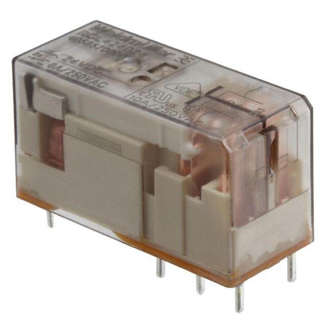
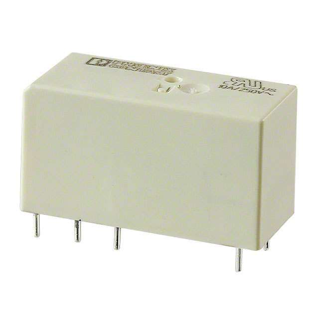
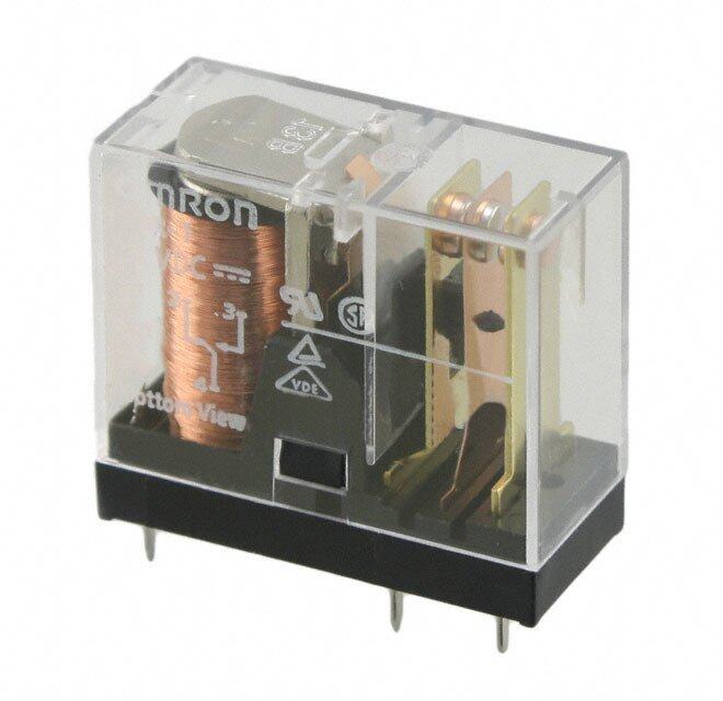
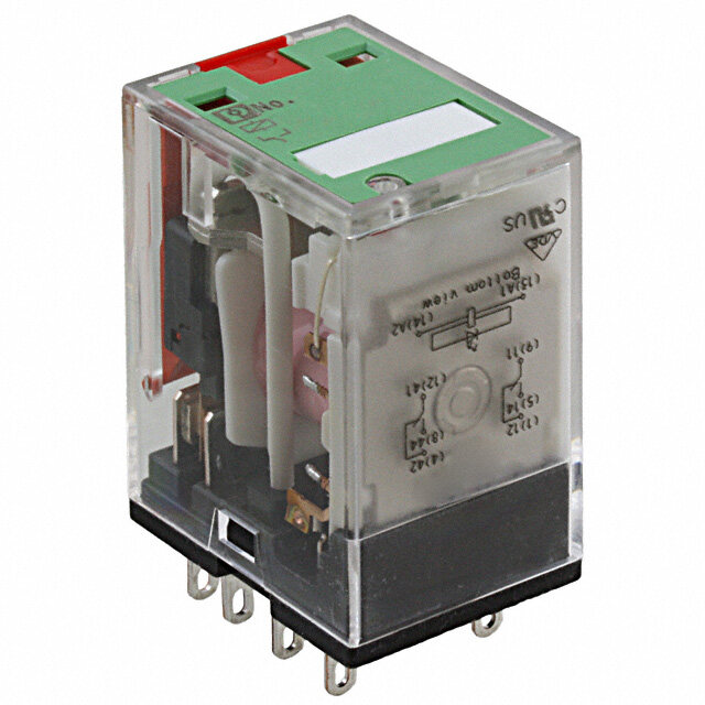
ICGOO电子元器件商城为您提供G8P-1C4P-V DC12由Omron Electronics LLC设计生产,在icgoo商城现货销售,并且可以通过原厂、代理商等渠道进行代购。 G8P-1C4P-V DC12价格参考。Omron Electronics LLCG8P-1C4P-V DC12封装/规格:功率继电器,高于 2 A, 通用 继电器 SPDT(1 Form C) 12VDC 线圈 通孔。您可以下载G8P-1C4P-V DC12参考资料、Datasheet数据手册功能说明书,资料中有G8P-1C4P-V DC12 详细功能的应用电路图电压和使用方法及教程。
Omron Electronics Inc-EMC Div生产的功率继电器型号G8P-1C4P-V DC12(额定电流高于2A)适用于多种工业和商业场景,其主要特点为高可靠性和稳定的电气性能。以下是该型号继电器的典型应用场景:

 1. 工业自动化设备
   - 用于控制电机、电磁阀、加热器等负载设备的通断。
   - 在生产线中,可作为信号转换或放大装置,实现对大功率负载的精确控制。

 2. 家用电器
   - 应用于需要较高电流控制的家电产品,如空调、冰箱、洗衣机等。
   - 控制压缩机、风扇或其他高功耗部件的运行状态。

 3. 电源管理系统
   - 在不间断电源(UPS)或备用电源系统中,用于切换主电源与备用电源。
   - 实现过载保护或短路保护功能。

 4. 汽车电子
   - 用于汽车内部的电气控制系统,例如车窗升降、座椅加热、灯光控制等。
   - 满足车载环境下的高可靠性要求,适应振动和温度变化。

 5. 通信设备
   - 在基站或网络设备中,用于电源管理或信号切换。
   - 提供稳定的大电流切换能力,确保通信系统的正常运行。

 6. 医疗设备
   - 用于需要高精度控制的医疗仪器,如监护仪、治疗设备等。
   - 确保设备在长时间运行中的安全性与稳定性。

 7. 照明系统
   - 控制LED灯、荧光灯或其他高功率照明设备的开关。
   - 支持智能照明系统的远程控制或定时控制功能。

 特性总结:
- 额定电压:DC12V
- 触点容量:支持高于2A的电流负载
- 工作环境:适应宽温范围,适合严苛工况
- 长寿命设计:适合频繁开关的应用场景

该型号继电器凭借其卓越的性能和可靠性,广泛应用于需要高电流控制的各种领域,能够满足多样化的需求。
| 参数 | 数值 |
| 产品目录 | |
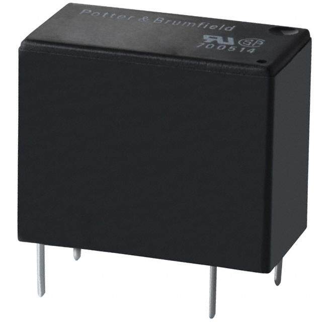
| 描述 | RELAY GEN PURPOSE SPDT 10A 12V通用继电器 Power PCB Relay |
| 产品分类 | |
| 品牌 | Omron Electronics |
| 产品手册 | |
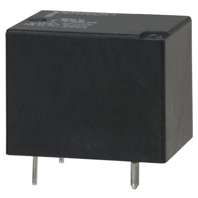
| 产品图片 |
|
| rohs | 符合RoHS无铅 / 符合限制有害物质指令(RoHS)规范要求 |
| 产品系列 | 通用继电器,Omron Electronics G8P-1C4P-V DC12G8P |
| mouser_ship_limit | 该产品可能需要其他文件才能进口到中国。 |
| 数据手册 | |
| 产品型号 | G8P-1C4P-V DC12 |
| 产品 | Power Relays |
| 产品种类 | 通用继电器 |
| 关闭电压(最小值) | 1.2 VDC |
| 其它名称 | G8P-1C4P-V DC12 BY OMZ |
| 其它有关文件 | |
| 功耗 | 900 mW |
| 包装 | 散装 |
| 商标 | Omron Electronics |
| 安装类型 | 通孔 |
| 安装风格 | Through Hole |
| 导通电压(最大值) | 9 VDC |
| 工作时间 | 15ms |
| 工作温度 | -55°C ~ 105°C |
| 工厂包装数量 | 50 |
| 开关电压 | 250VAC,28VDC - 最小值 |
| 标准包装 | 50 |
| 特性 | 绝缘 - F 级,密封式 - 全部 |
| 端子类型 | PC 引脚 |
| 端接类型 | Solder Pin |
| 类型 | Standard |
| 系列 | G8PT |
| 线圈功率 | 900 mW |
| 线圈电压 | 5 V to 110 V |
| 线圈电流 | 77 mA |
| 线圈电阻 | 155 Ohms |
| 线圈端接 | Solder Pin |
| 线圈类型 | Non-Latching |
| 继电器类型 | 通用 |
| 触头外形 | SPDT(1 C 型) |
| 触头材料 | 银镉氧化物(AgCdO) |
| 触点形式 | SPDT (1 Form C) |
| 触点材料 | Silver Cadmium Oxide |
| 触点端接 | PCB |
| 释放时间 | 10ms |
| 零件号别名 | 681966 BY DC12 G8P-1C4P-V G8P-1C4P-V-DC12-BY-OMZ G8P1C4PVDC12BYOMZ G8P1C4PVDC12NCG8P-1C4P-V OMZ |
| 额定接触(电流) | 10A |


.jpg)

- 商务部:美国ITC正式对集成电路等产品启动337调查
- 曝三星4nm工艺存在良率问题 高通将骁龙8 Gen1或转产台积电
- 太阳诱电将投资9.5亿元在常州建新厂生产MLCC 预计2023年完工
- 英特尔发布欧洲新工厂建设计划 深化IDM 2.0 战略
- 台积电先进制程称霸业界 有大客户加持明年业绩稳了
- 达到5530亿美元!SIA预计今年全球半导体销售额将创下新高
- 英特尔拟将自动驾驶子公司Mobileye上市 估值或超500亿美元
- 三星加码芯片和SET,合并消费电子和移动部门,撤换高东真等 CEO
- 三星电子宣布重大人事变动 还合并消费电子和移动部门
- 海关总署:前11个月进口集成电路产品价值2.52万亿元 增长14.8%


PDF Datasheet 数据手册内容提取
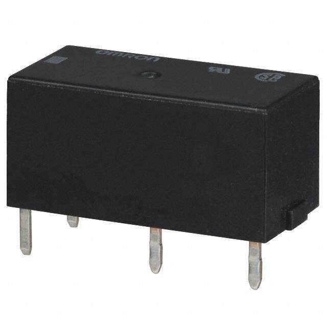
Power PCB Relay G8P (cid:1) Up to 30 A switching capacity in compact package (cid:1) Available with quick-connect terminals for easy load connecting (cid:1) UL Class F coil insulation standard (cid:1) Complies with UL 873 and UL 508 column A spacings up to 300 V (cid:1) Minimum 6kV Impulse Surge Withstand (cid:1) Ideal for home and industrial appliances, HVAC (heating, ventilating, and air condi- tioning), and many other applications (cid:1) UL/CSA approvals, VDE pending Ordering Information To Order: Select the part number and add the desired coil voltage rating, (e.g., G8P-1A4P-DC12). Mounting type Contact form Construction Part number PCB SPST-NO Open frame G8P-1AP Sealed with ventable nib G8P-1A4P SPDT Open frame G8P-1CP Sealed with ventable nib G8P-1C4P PCB & Quick Connect SPST-NO Open frame G8P-1ATP load terminals Sealed with ventable nib G8P-1A4TP SPDT Open frame G8P-1CTP Sealed with ventable nib G8P-1C4TP Flange mount Quick SPST-NO Vented G8P-1A2T-F Connect terminals SPDT Vented G8P-1C2T-F Note: Load terminals are .250" Quick Connect. Coil terminals on Flange Mount versions are .187" Quick Connect. Specifications (cid:1) CONTACT DATA Type SPST-NO SPDT Rated load 30 A at 250 VAC, 20 A at 28 VDC 20/10 A* at 250 VAC, 20/10 A at 28 VDC Contact material AgCdO Carry current 30 A 20/10 A* Max. operating voltage 250 VAC, 28 VDC Max. operating current AC 30 A, DC 20 A AC 20/10 A, DC 20/10 A* Max. switching capacity 7,500 VA, 560 W 5,000/2,500 VA, 560/280 W* Min. permissible load DC 5 V, 500 mA * NO contact/NC contact
G8P G8P (cid:1) COIL DATA Rated Rated Coil Pick-up Dropout Maximum Power voltage current resistance voltage voltage voltage consumption (VDC) (mA) (Ω) (mW) % of rated voltage 5 185 27 75% max. 10% min. 120% max. Approx. 900 9 93 97 12 77 155 24 36 660 48 19 2480 110 9 12400 Note: The rated current and coil resistance are measured at a coil temperature of 23°C (73°F) with tolerances of ±10%. (cid:1) CHARACTERISTICS Contact resistance 100 mΩ max. (measured with 5 VDC, 1 A) Operate time 15 ms max. Release time 10 ms max. Insulation resistance 10 MΩ min. (at 500 VDC) Dielectric strength 2,500 VAC, 50/60 Hz for 1 minute (coil to contacts), 1,500 VAC, 50/60 Hz for 1 minute (between contacts) Impulse surge withstand 6,000 V between coil to contacts (1.2 µs/50µs & 100 kHz ring wave per IEC 1000-4-12) Vibration Mechanical durability 10 to 55 Hz, 1.65 mm (0.06 in) double amplitude for 2 hours Malfunction durability 10 to 55 Hz, 1.65 mm (0.06 in) double amplitude for 5 minutes Shock Mechanical durability 1,000 m/s2 (approx. 100 G) Malfunction durability 100 m/s2 (approx. 10 G) Ambient temperature -55° to 105°C (-67° to 221°F) Humidity 45% to 85% RH Service life Mechanical 10 million operations minimum Electrical 100,000 operations at rated load (minimum) Note: Data shown are of initial value. Operate and release times excluding bounce. (cid:1) CHARACTERISTIC DATA Maximum switching capacity SPST-NO SPDT A) A) nt ( nt ( e e urr urr c c g g n n ati ati er er p p o o d d e e at at R R Rated operating voltage (V) Rated operating voltage (V) 2
G8P G8P (cid:1) CHARACTERISTIC DATA Electrical service life SPST-NO SPDT s) s) n n o o ati ati er er p p o o 0 3 0 3 1 1 x x e ( e ( e lif e lif c c vi vi er er S S Load current (A) Load current (A) Dimensions Unit: mm (inch) (cid:1) RELAYS Open frame, PCB terminals Terminal arrangement/ Mounting holes Internal connections (Bottom view) (Bottom view) 2.54 (0.10) 15.3 1.4 2.54 (0.60) 7.6 (0.06) 3 4* (0.10) (0.30) 2.5 (0.10) Max. 24 (0.94) 2 Typ. 23.5 (0.93) 3.8 (0.15) 4 6 (0.16) 10.2 5 (0.40) Max. 10.9 (0.43) 1.7 Typ. 10.4 (0.41) (0.07) *Note: Terminal #4 is omitted Max. 28.5 (1.12) Typ. 28 (1.10) on SPST-NO version. 3.8 (0.15) Max. 17.4 Two (10..10 4±30 .±10 d.0ia0.4 h)oles (03..154) Three( 20..10 8± 0±.02. 0d0ia8.) holes (0.69) Typ. 16.9 (0.67) 0) (01.25.08) 5 (0.1 (07..360) (03..185) (100.4.20) (03..185) 4.4 ±0.5 2. 17.8 (0.17 ±0.020) (0.70) 3
G8P G8P Unit: mm (inch) Sealed, PCB terminals Terminal arrangement/ Mounting holes Max. 18.5 (0.73) Internal connections (Bottom view) Typ. 18 (0.71) (Bottom view) 2.54 15.3 (0.10) (0.60) 7.6 3.2 2.54 2.5 (0.10) (0.30) (0.13) (0.10) 3 4* Ma(0x..8 220).9 Max. 27.7 2 (03..185) (05..262) Typ. 20.4 (1.09) (0.80) Typ. 27.2 (1.07) 6 10.2 5 (0.40) 3.8 (0.15) Max. 14.1 (0.56) *Note: Terminal #4 is omitted Max. 5.7 Typ. 13.6 (0.54) on SPST-NO version. 3.8 (0.15) (0.22) Max. 32.1 (1.26) Typ. 5.2 Typ. 31.6 (1.24) (0.20) Three 2.1 ±0.2 dia. holes 5.5 (0.083 ±0.008 dia.) Two 1.1 ±0.1 dia. holes (0.22) Max. 20.1 (0.043 ±0.004 dia.) (0.79) Typ. 19.6 (0.77) 0) (0.133.3 ±± 00..0520) (0.00.415) (102.5.80) 2.5 (0.1 (07..360) (03..185) (100.4.20) (03..185) Open frame, PCB with Quick Connect terminals Terminal arrangement/ Mounting holes Internal connections 2.54 (Bottom view) (Bottom view) (0.10) 15.3 7.6 1.4 2.54 (0.60) (0.30) (0.06) (0.10) 2.5 (0.10) 3 4* 3.8 2 (0.15) Max. 24 (0.94) 4 Typ. 23.5 (0.93) 10.2 (0.16) (0.40) 6 1.7 (0.07) 5 Max. 10.9 (0.43) Typ. 10.4 (0.41) *Note: Terminal #4 is omitted 3.8 (0.15) on SPST-NO version. Max. 28.5 (1.12) Typ. 28 (1.10) 3.5 Three 2.1 ±0.2 dia. holes Two 1.1 ±0.1 dia. holes (0.14) (0.083 ±0.008 dia.) .250" Quick Connect (0.043 ±0.004 dia.) terminals 9.8 (0.39) Max. 17.4 (0.69) Typ. 16.9 (0.67) (0.147.4 ±±00..0520) (102.5.80) 0.10) (07..360) (100.4.20) 5 ( 3.8 17.8 3.8 2. (0.15) (0.70) (0.15) 4
G8P G8P Unit: mm (inch) Sealed, PCB with Quick Connect terminals Terminal arrangement/ Mounting holes Internal connections (Bottom view) 2.54 (Bottom view) .250" Quick Connect terminals (0.10) 15.3 3.2 2.54 (0.60) 7.6 (0.13) (0.10) 2.5 (0.10) (0.30) 3 4* 3.8 COM (0.15) 2 Max. 27.5 (1.08) 6 Typ. 27 (1.06) NO NC (0.24) 10.2 6 (0.40) 5 3.8 (0.15) Max. 31.9 (1.26) 3.4 (0.13) Typ. 31.4 (1.24) *Note: Terminal #4 is omitted on SPST-NO version. Three 2.1 ±0.2 dia. holes Tw(o0 .10.413 ± ±00..10 0d4ia .d hiao.)les (05..252) (0.083 ±0.008 dia.) Max. 28.3 (1.11) Typ. 27.8 (1.09) 19.6 (0.77) 0.4 (0.02) 12.8 10) 7.6 10.2 (0.133.3 ±±00..0520) (0.50) 2.5 (0. (0.30) (03..185) (0.40) (03..185) Flange mount Terminal arrangement/ Mounting holes Internal connections (Bottom view) (Bottom view) .250" Quick Connect terminals 4* 3 Ma(1x..0 297).7 NC NO 3(0.6.1 d4i)a. 2 3.6 dia. Typ. 27.2 (0.14) (1.07) COM 6 0.8 dia (0.03) 5 .187" Quick Connect terminals 43.4 ± 0.1 Max. 32 (1.26) *Note: Terminal #4 is omitted (1.71 ± 0.004) Typ. 31.5 (1.24) on SPST-NO version. Max. 28.3 (1.11) Typ. 27.8 Max. 20.1 (1.09) (0.79) Typ. 19.6 (0.77) Max. 50.3 (1.98) Typ. 49.8 (1.96) Note: Allow air circulation within the sealed type G8P by removing the ventilation nib from the cover after soldering and cleaning is complete. 5
G8P G8P (cid:1) APPROVALS UL Recognized (File No. E41643), CSA Certified (File No. LR34815) Contact form Coil ratings Contact ratings SPST-NO 5 to 110 VDC 30A, 277 VAC (G.P./Res.) 30A, 250 VAC, 100k ops. (Res.) 20A, 120-240 VAC, 70°C, 100,000 cycles (G.P./Res.) 20A, 28 VDC (Res.) 20A, 240 VAC, 105°C, 100,000 cycles (Res.) 1 HP, 125-250 VAC 2 HP, 250 VAC A300 Pilot Duty 12FLA, 72LRA, 250 VAC, 100,000 cycles 20 FLA, 96 LRA, 125 VAC, 100,000 cycles 5A, 250 VAC (Tungsten) 20A, 120-277 VAC (Ballast) SPDT 5 to 110 VDC NO/NC 30A/ 30A, 250 VAC (Res.) 20A/ 15A, 120-240 VAC, 105°C, 100,000 cycles (Res.) 20A/ 10A, 120-240 VAC, 70°C, 100,000 cycles (G.P./Res.) 20A/ 10A, 28 VDC (Res.) 1/2 HP/ 1/2 HP, 125 VAC, 100,000 cycles 2 HP/ 1/2 HP, 250 VAC 1 HP/ 1/4 HP, 125 VAC B150 Pilot Duty 5A/ 3A, 250 VAC (Tungsten) 6A/ 3A, 277 VAC (Ballast) Note: 1. The rated values approved by each of the safety standards (e.g., UL, CSA) may be different from the performance characteristics individually defined in this catalog. 2. For information on additional ratings not included in this catalog, contact your local Omron Representative. 3. In the interest of product improvement, specifications are subject to change. OMRON ELECTRONICS, INC. OMRON CANADA, INC. One East Commerce Drive 885 Milner Avenue Schaumburg, IL 60173 Scarborough, Ontario M1B 5V8 1-800-55-OMRON 416-286-6465 Cat. No. J03RAD2 8/00/2.5M Specifications subject to change without notice. Printed in the U.S.A. 6