ICGOO在线商城 > 继电器 > 功率继电器,高于 2 A > G7L-2A-BUBJ-CB-IN AC24

 Datasheet下载
- 型号: G7L-2A-BUBJ-CB-IN AC24
- 制造商: Omron Electronics LLC
- 库位|库存: xxxx|xxxx
- 要求:
| 数量阶梯 | 香港交货 | 国内含税 |
| +xxxx | $xxxx | ¥xxxx |
查看当月历史价格
查看今年历史价格
G7L-2A-BUBJ-CB-IN AC24产品简介:
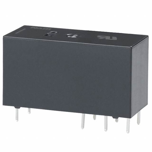
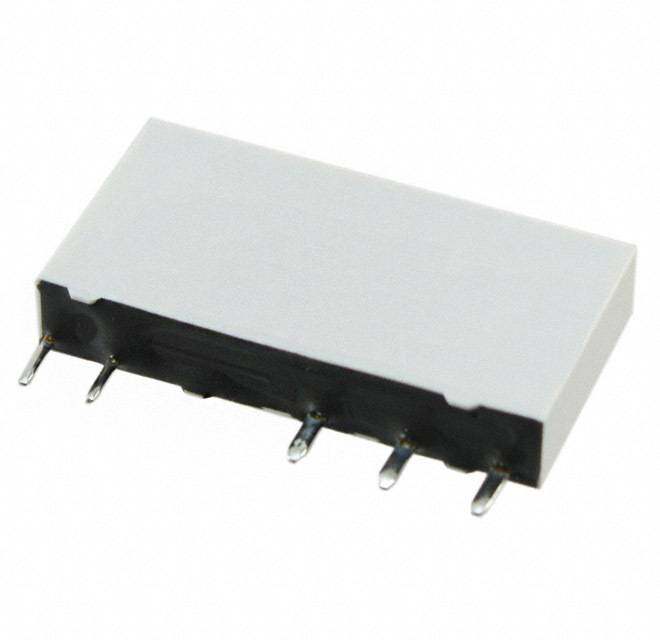
ICGOO电子元器件商城为您提供G7L-2A-BUBJ-CB-IN AC24由Omron Electronics LLC设计生产,在icgoo商城现货销售,并且可以通过原厂、代理商等渠道进行代购。 G7L-2A-BUBJ-CB-IN AC24价格参考¥109.51-¥162.27。Omron Electronics LLCG7L-2A-BUBJ-CB-IN AC24封装/规格:功率继电器,高于 2 A, 通用 继电器 DPST-NO(2 Form A) 24VAC 线圈 底座安装。您可以下载G7L-2A-BUBJ-CB-IN AC24参考资料、Datasheet数据手册功能说明书,资料中有G7L-2A-BUBJ-CB-IN AC24 详细功能的应用电路图电压和使用方法及教程。
Omron Electronics Inc-EMC Div生产的G7L-2A-BUBJ-CB-IN AC24功率继电器是一款适用于工业和商业领域的高性能继电器,其额定电流为2 A(高于2 A的负载能力),支持24V AC线圈电压。以下是该型号的一些典型应用场景:

 1. 工业自动化设备
   - PLC控制系统:用于可编程逻辑控制器(PLC)中,控制高功率负载的开关。
   - 传感器与执行器接口:在传感器信号检测后,驱动执行器(如电机、电磁阀等)运行。
   - 生产线设备:控制输送带电机、气动装置或其他高功率组件。

 2.  HVAC系统
   - 空调与制冷设备:用于控制压缩机、风扇或加热元件的启停。
   - 温控系统:根据温度变化切换电路,实现精确的环境控制。

 3. 照明系统
   - 工业照明:控制大功率LED灯或荧光灯的开关。
   - 智能照明:结合定时器或传感器,实现自动化照明管理。

 4. 家电设备
   - 家用电器:如洗衣机、烘干机、微波炉等,用于控制加热元件或电机。
   - 智能家居系统:通过继电器实现对家电设备的远程控制。

 5. 电力与能源管理
   - 备用电源切换:在主电源中断时,自动切换到备用电源。
   - 电池管理系统:控制电池充放电回路的通断。

 6. 医疗设备
   - 诊断仪器:用于控制内部电路或外部设备的供电。
   - 治疗设备:如理疗仪、超声波设备等,需要精确控制功率输出。

 7. 汽车电子
   - 车载设备:控制车用空调、座椅加热器或灯光系统。
   - 新能源汽车:用于电池管理系统或充电电路的切换。

 特性优势
- 高可靠性:Omron继电器以其长寿命和高稳定性著称,适合频繁开关的应用场景。
- 小型化设计:便于集成到紧凑型设备中。
- 耐高温性能:能够在恶劣环境下稳定工作。

总结来说,G7L-2A-BUBJ-CB-IN AC24继电器广泛应用于需要高电流负载控制的场景,特别是在工业自动化、家电、照明和电力管理等领域表现优异。
| 参数 | 数值 |
| 产品目录 | |
| 描述 | RELAY GEN PURPOSE DPST 25A 24V通用继电器 25A GP RY 2A SCREW P NL TEST HP |
| 产品分类 | |
| 品牌 | Omron Electronics |
| 产品手册 | |
| 产品图片 | |
| rohs | 符合RoHS无铅 / 符合限制有害物质指令(RoHS)规范要求 |
| 产品系列 | 通用继电器,Omron Electronics G7L-2A-BUBJ-CB-IN AC24G7L |
| mouser_ship_limit | 该产品可能需要其他文档才能发货到中国。 |
| 数据手册 | |
| 产品型号 | G7L-2A-BUBJ-CB-IN AC24 |
| 产品种类 | Relays - General Purpose |
| 关闭电压(最小值) | 3.6 VAC |
| 其它名称 | G7L2ABUBJCBINAC24 |
| 其它有关文件 | |
| 功耗 | 1.7 VA to 2.5 VA |
| 包装 | 散装 |
| 商标 | Omron Electronics |
| 安装类型 | Bracket |
| 安装风格 | Panel |
| 导通电压(最大值) | 18 VAC |
| 工作时间 | 30ms |
| 工作温度 | -25°C ~ 60°C |
| 开关电压 | 250VAC - 最小值 |
| 标准包装 | 1 |
| 特性 | 绝缘 - B 类,测试按钮 |
| 端子类型 | 螺丝端子 |
| 端接类型 | Screw |
| 系列 | G7L(STANDARD) |
| 线圈功率 | 2.5 VA |
| 线圈电压 | 24 VAC |
| 线圈电流 | 71mA |
| 线圈电阻 | 303 欧姆 |
| 线圈端接 | Screw |
| 线圈类型 | Standard |
| 继电器类型 | 通用 |
| 触头外形 | DPST(2 A 型) |
| 触头材料 | 银锡铟(AgSnIn) |
| 触点形式 | 2 Form A (DPST-NO) |
| 触点材料 | Silver |
| 触点端接 | Screw |
| 释放时间 | 30ms |
| 零件号别名 | G7L2ABUBJCBINAC24NC |
| 额定接触(电流) | 25A |


- 商务部:美国ITC正式对集成电路等产品启动337调查
- 曝三星4nm工艺存在良率问题 高通将骁龙8 Gen1或转产台积电
- 太阳诱电将投资9.5亿元在常州建新厂生产MLCC 预计2023年完工
- 英特尔发布欧洲新工厂建设计划 深化IDM 2.0 战略
- 台积电先进制程称霸业界 有大客户加持明年业绩稳了
- 达到5530亿美元!SIA预计今年全球半导体销售额将创下新高
- 英特尔拟将自动驾驶子公司Mobileye上市 估值或超500亿美元
- 三星加码芯片和SET,合并消费电子和移动部门,撤换高东真等 CEO
- 三星电子宣布重大人事变动 还合并消费电子和移动部门
- 海关总署:前11个月进口集成电路产品价值2.52万亿元 增长14.8%

.jpg)
PDF Datasheet 数据手册内容提取
G7L Power Relay A High-capacity, High-dielectric-strength Relay Compatible with Momentary Voltage Drops •No contact chattering for momentary voltage drops up to 50% of rated voltage. •Wide-range AC-activated coil that handles 100 to 120 or 200 to 240 VAC at either 50 or 60 Hz. •Miniature size for maximum switching power, particularly for inductive loads. •Flame-resistance materials (UL94V-0-qualifying) used for all insulation material. •Quick-connect, screw, and PCB terminals, and DIN track mounting available. Note.Accessories: E-bracket, Adapter, Front-connecting socket and Cover sold separately. •Conforms to UL, CSA, TUV and meets IEC950. •Safety design with contact gap of 3 mm. RoHS Compliant G 7 ■Model Number Legend ■Application Examples L G7L-@@-@@@ (cid:120) Compressors for air conditioners — — — — — and heater switching controllers. 1 2 3 4 5 (cid:120) Switching controllers for power tools 1. Number of Poles 3. Terminal Shape 4. Mounting Construction or motors. 1: 1 pole T:Quick connect Blank:E-bracket (cid:120) Power controllers for water heaters. 2: 2 poles terminals (#250) UB :Upper bracket (cid:120) Power controllers for dryers. B:Screw terminals (cid:120) Lamp controls, motor drivers, and 2. Contact Form 5. Special Functions P:PCB terminals power supply switching in copy A: @PST-NO J :With test button machines, facsimile machines, and ■Model Configuration other office equipment. (cid:120) Lighting controllers. (cid:120) Power controllers for packers or Terminal Quick-connect terminals Screw terminals PCB terminals food processing equipment. (cid:120) Magnetron control in microwaves. (cid:120) Power controllers for Uninterruptible Power Supply (UPS) Classification Contact form E-bracket − SPST-NO G7L-1A-T G7L-1A-B − mounting DPST-NO G7L-2A-T G7L-2A-B − (E-bracket is With test SPST-NO G7L-1A-TJ G7L-1A-BJ − sold separately) button DPST-NO G7L-2A-TJ G7L-2A-BJ − − SPST-NO G7L-1A-TUB G7L-1A-BUB − Upper bracket DPST-NO G7L-2A-TUB G7L-2A-BUB − mounting With test SPST-NO G7L-1A-TUBJ G7L-1A-BUBJ − button DPST-NO G7L-2A-TUBJ G7L-2A-BUBJ − PCB mounting − DSPPSSTT--NNOO −− −− GG77LL--12AA--PP ■List of E-bracket Mounting Models Mounting E-brackets DIN Track Front-connecting Mounting Socket Adapter Contact Terminal form Model Test button G7L-1A-T − (cid:123) (cid:123) (cid:123) Quick- SPST-NO G7L-1A-TJ With test button (cid:123) (cid:123) (cid:123) connect G7L-2A-T − (cid:123) (cid:123) (cid:123) terminals DPST-NO G7L-2A-TJ With test button (cid:123) (cid:123) (cid:123) G7L-1A-B − (cid:123) (cid:123) − Screw SPST-NO G7L-1A-BJ With test button (cid:123) (cid:123) − Note.Accessories: E-bracket (R99-07), Adapter (P7LF-D), terminals G7L-2A-B − (cid:123) (cid:123) − Front-connecting socket (P7LF-06) and Cover DPST-NO G7L-2A-BJ With test button (cid:123) (cid:123) − (P7LF-C) sold separately. 1
G7L Power Relay ■Ordering Information E-bracket/Adapter/Socket Mounting E-bracket/Adapter/Socket Mounting (with test button) Quick-connect Terminal Quick-connect Terminal Number Minimum Number Minimum Model Rated coil voltage Model Rated coil voltage of poles packing unit of poles packing unit AC: 12, 24, 100/120, 200/240 AC: 24, 100/120, 200/240 1 pole G7L-1A-T 1 pole G7L-1A-TJ DC: 6, 12, 24, 48, 100 DC: 12, 24, 48, 100 20 pcs./tray 20 pcs./tray AC: 12, 24, 50, 100/120, 200/240 AC: 24, 100/120, 200/240 2 poles G7L-2A-T 2 poles G7L-2A-TJ DC: 6, 12, 24, 48, 100 DC: 6, 12, 24, 48, 100 Upper Bracket Mounting Upper Bracket Mounting (with test button) Quick-connect Terminal Quick-connect Terminal Number Minimum Number Minimum Model Rated coil voltage Model Rated coil voltage of poles packing unit of poles packing unit AC: 12, 24, 100/120, 200/240 AC: 24, 100/120, 200/240 1 pole G7L-1A-TUB 1 pole G7L-1A-TUBJ DC: 6, 12, 24, 48, 100 DC: 6, 12, 24, 48, 100 20 pcs./tray 20 pcs./tray AC: 12, 24, 50, 100/120, 200/240 AC: 12, 24, 50, 100/120, 200/240 2 poles G7L-2A-TUB 2 poles G7L-2A-TUBJ DC: 6, 12, 24, 48, 100 DC: 6, 12, 24, 48, 100 E-bracket/Adapter Mounting E-bracket/Adapter Mounting (with test button) Screw Terminal Screw Terminal Number Minimum Number Minimum Model Rated coil voltage Model Rated coil voltage of poles packing unit of poles packing unit AC: 12, 24, 100/120, 200/240 AC: 12, 24, 100/120, 200/240 1 pole G7L-1A-B 1 pole G7L-1A-BJ DC: 6, 12, 24, 48, 100 DC: 12, 24 20 pcs./tray 20 pcs./tray G AC: 12, 24, 100/120, 200/240 AC: 24, 100/120, 200/240 7 2 poles G7L-2A-B 2 poles G7L-2A-BJ DC: 12, 24, 48, 100 DC: 12, 24, 48, 100 L Upper Bracket Mounting Upper Bracket Mounting (with test button) Screw Terminal Screw Terminal Number Minimum Number Minimum Model Rated coil voltage Model Rated coil voltage of poles packing unit of poles packing unit AC: 24, 100/120, 200/240 AC: 24, 100/120, 200/240 1 pole G7L-1A-BUB 1 pole G7L-1A-BUBJ DC: 6, 12, 24, 48, 100 DC: 6, 12, 24, 48 20 pcs./tray 20 pcs./tray AC: 12, 24, 50, 100/120, 200/240 AC: 24, 100/120, 200/240 2 poles G7L-2A-BUB 2 poles G7L-2A-BUBJ DC: 6, 12, 24, 48, 100 DC: 6, 12, 24, 48, 100 PCB Mounting Note 1.When ordering, add the rated coil voltage to the model number. Example: G7L-1A-T AC12 Number Minimum Model Rated coil voltage Rated coil voltage of poles packing unit However, the notation of the coil voltage on the product case as well as AC: 100/120, 200/240 on the packing will be marked as @@ VDC. 1 pole G7L-1A-P DC: 12, 24, 48, 100 Note 2.Refer to the precautions on PCB Relays provided in General AC: 24, 100/120, 200/240 20 pcs./tray Information of the Relay Product Data Book, and "w -@-3" for coil 2 poles G7L-2A-P characteristics of AC operation. DC: 6, 12, 24, 48, 100 E-bracket/Adaptor/Socket/Cover DIN Track Mounting Accessories Applicable Relay Minimum Applicable products Name Model Minimum models Name Model packing unit packing unit G7L-1A-T PFP-100N G7L-1A-TJ E-bracket R99-07 10 pcs. DIN Track PFP-50N G7L-1A-B Adaptor Surface PFP-100N2 10 pcs. G7L-1A-BJ Connection Socket G7L-2A-T End plate PFP-M G7L-2A-TJ Spacer PFP-S G7L-2A-B Adapter P7LF-D 1 pcs. Note.Order the models above in increments of the minimum quantity packaged. G7L-2A-BJ G7L-1A-T G7L-1A-TJ Front-connecting P7LF-06 1 pcs. G7L-2A-T Socket G7L-2A-TJ G7L-1A-B G7L-1A-BJ G7L-1A-BUB G7L-1A-BUBJ Cover P7LF-C 1 pcs. G7L-2A-B G7L-2A-BJ G7L-2A-BUB G7L-2A-BUBJ Note.Order the models above in increments of the minimum quantity packaged. 2
G7L Power Relay ■Ratings ■Characteristics Coil Contact resistance *1 50 mΩ max. Item Max. Operate time *2 30 ms max. Rated Coil Coil inductance (H) Muvsot lotapgeerate Muvsot lrtealgeease permissible Power Release time *3 30 ms max. current resistance voltage consumption Max. Mechanical 1,800 operations/hr (mA) (Ω) Armature Armature On the basis of rated voltage (VA-W) operating Rated voltage ON OFF frequency Rated load 1,800 operations/hr 12 VAC 142 Insulation resistance *3 1,000 MΩ min 24 VAC 71 75% max. 15% min. 110% Approx. 1.7 Between coil and 4,000 VAC min., 50/60 Hz 50 VAC 34 to 2.5 contacts for 1 min 100 to 120 VAC 17.0 to 20.4 75 V max. 18 V min. 132 V Between contacts Dielectric 200 to 240 VAC 8.5 to 10.2 150 V max. 36 V min. 264 V strength of same polarity 2,000 VAC, 50/60 Hz for 6 VDC 317 18.9 0.09 0.21 Between contacts 1min 12 VDC 158 75 0.37 0.88 of different polarity (DPST-NO model) 24 VDC 79 303 1.42 3.54 75% max. 15% min. 110% Approx. 1.9 10,000 V between coil and 48 VDC 40 1220 6.1 15.3 Impulse withstand voltage contact *4 100 VDC 19 5260 21.3 60.0 10 to 55 to 10 Hz, 0.75 mm Note 1.The rated current and coil resistance are measured at a coil temperature of 23°C with tolerances of Destruction single amplitude +15%/-20% for AC rated current and ±15% for DC coil resistance. Vibration (1.5 mm double amplitude) 2.The inductances shown above are reference values. resistance 10 to 55 to 10 Hz, 0.75 mm 3.Performance characteristic data are measured at a coil temperature of 23°C. Malfunction single amplitude (1.5 mm double amplitude) 4.The maximum allowable coil voltage refers to the maximum value in a varying range of operating power voltage, measured at ambient temperature 23°C. Shock Destruction 1,000 m/s2 5.The "to" (for example "100 to 120") represents the range of rated voltages. resistance Malfunction 100 m/s2 1,000,000 operations min. Contacts Mechanical (at 1,800 operations/hr) Endurance 100,000 operations min. Contact Form G7L-1A-T@ G7L-2A-T@ G7L-1A-P Electrical *5 (at 1,800 operations/hr G7L-1A-B@ G7L-2A-B@ G7L-2A-P under rated load) load Resistive Inductive load Resistive Inductive Resistive Inductive Failure rate (P level) 100 mA at 5 VDC Item load (cosφ = 0.4) load (coslφo a=d 0.4) load (coslφo a=d 0.4) (reference value *6) Approx. 90 g: G Quick-connect terminal 7 Contact type Double break models L Contact material Ag alloy Weight Approx. 100 g: Rated load 30 A at 220 VAC 25 A at 220 VAC 25 A at 220 VAC 20 A at 220 VAC PCB terminal models Rated carry current 30 A 25 A 20 A Approx. 120 g: Screw terminal models Max. switching voltage 250 VAC Note. The values given above are initial values. Max. switching *1. Measurement conditions: 5 VDC, 1 A, voltage drop current 30 A 25 A 20 A method. *2. Measurement conditions: Rated operating voltage applied, Note.When using B-series (screw) products, since the screw diameter of the contact terminal is M4, be careful not including contact bounce. that the contact current should be 20 A or less according to JET standard (electrical appliance and material Ambient temperature: 23°C control law of Japan). *3. Measurement conditions: The insulation resistance was measured with a 500-VDC megohmmeter at the same locations as the dielectric strength was measured. *4. JEC-212 (1981) Standard Impulse Wave Type (1.2×50μs). *5. Ambient temperature: 23°C *6. This value was measured at a switching frequency of 60 operations/min. -25°C to 60°C Ambient operating temperature (with no icing or condensation) Ambient operating humidity 5% to 85% ■Engineering Data G7L-1A-T (TJ) (TUB) (TUBJ) G7L-2A-T (TJ) (TUB) (TUBJ) G7L-1A-P Ambient Temperature vs. Operate G7L-1A-B (BJ) (BUB) (BUBJ) G7L-2A-B (BJ) (BUB) (BUBJ) G7L-2A-P and Release Voltage Maximum Switching Power Maximum Switching Power Maximum Switching Power G7L-1A VAC (60 Hz) Switching current (A)103125000007 A(cCo sinφ d=u c0t.i4v)e loadAC resistive load Switching current (A)103125000007 AA(cCCo srinφe ds=uis c0tit.vi4ve)e l oloaadd Switching current (A)5213000057 AA(cCCo srinφe ds=uis c0tit.vi4ve)e l oloaadd Operate and Release voltages (%)108640000 ORepleeraastee vvoollttaaggee 5 5 3 3 3 20 1 1 1 0 10 30 5070100 300 5001,000 10 30 5070100 300 5001,000 10 30 5070100 300 500 -40 -20 0 20 40 60 80 Switching voltage (V) Ambient temperature (°C) Switching voltage (V) Ambient temperature (°C) Endurance Endurance Endurance G7L-1A VDC 4Endurance (x 10 operations)531000753000000 220 VAC resistive load 4Endurance (x 10 operations)531000753000000 220 VAC resistive load 4Endurance (x 10 operations)531000753000000 220 VAC resistive load Operate and Release voltages (%)108640000 ORepleeraastee vvoollttaaggee 220 VAC 220 VAC 10 i(ncdousφct i=v e0 .l4o)ad 10 i(ncdousφct i=v e0 .l4o)ad 10 2in2d0u cVtAivCe load 20 7 7 7 (cosφ = 0.4) 5 5 5 0 0 5 10 15 20 25 30 0 5 10 15 20 25 30 0 5 10 15 20 25 30 -40 -20 0 20 40 60 80 Switching current (A) Switching current (A) Switching current (A) Ambient temperature (°C) 3
G7L Power Relay Ambient Temperature vs. Shock Malfunction Coil Temperature Rise G7L-2A-T (TUB) 100 to 120 VAC G7L-1A 120 VAC (50 Hz) G7L-1A VDC Coil Temperature Rise ()°C86420000N=5 013 50A AA Coil Temperature Rise ()°C86420000N=5 013 50A AA 5ZX50000440000303000202000110123000000000Y234511000000000001002000203000304004000500Z5X0''0NTSe t=as 5nt dmaertdh: od: 1Tmwateae0palhYaoas0pcestnlf hml uypgvmX inii a/nen3seclgc u2 at6a eiesos x d uhn3eairo rsteote c.iwmdcckXch t 'eaituoiocsfrnt h retseh rZ d e 400 Z' 0 0 -40 -20 0 20Ambie4n0t temper6a0ture (°8C0) -40 -20 0 20Ambie4n0t temper6a0ture (°8C0) 500Y' Unit: (m/s2) Y' Shock direction Momentary Voltage Drop Test G7L-2A-T (TUB) 100 to 120 VAC Voltage distribution of wave e which Test Circuit Wave resulted from test chattering does not occur. Ch1 ON Without chattering mber of Relays 86n=10 (contact) OFF Nu 4 Rated Ch1 C(cho2il)voltage e G Ch2 2 7 L 0 20 40 60 80 100 On the basis of rated voltage (%) Characteristic variation resulted from different mounting directions G7L-2A-T (TUB) 100 to 120 VAC Operate time Release time Operate voltage Release voltage Time (ms)22115050N O= p5erate time Time (ms)33225050N =R 5elease time On the basis of rated voltage (%)87650000N =O p5erate voltage On the basis of rated voltage (%)54320000N = 5Release voltage 5 15 40 10 0 Top A A' B B' C C' 0 Top A A' B B' C C' 0 Top A A' B B' C C' 0 Top A A' B B' C C' Bottom(Standard) (Note) Mounting direction Bottom(Standard) (Note) Mounting direction Bottom(Standard) (Note) Mounting direction Bottom(Standard) (Note) Mounting direction (Note.)The mounting direction A’ deteriorates switching performance. Actual Load Endurance Test G7L-2A 100 to 200 VAC Operate and Release voltages Operate and Release voltages N = 5 Contact resistance N = 5 Contact resistance On the basis of rated voltage (%)7654300000N = 5 ORepleeraastee vvoollttaaggee ΩContact resistance (m)108640000N = 5 On the basis of rated voltage (%)7654300000 OvRoepltleearagasetee N = 5 ΩContact resistance (m)54320000N = 5 voltage 20 20 20 10 10 10 0 0 0 0 0.50.71 3 5 7 10 30 50 0.50.71 3 5 7 10 30 50 0.050.070.1 0.3 0.5 1 3 5 0.050.070.1 0.3 0.5 1 3 5 Switching operations (×104 operations) Switching operations (×104 operations) Switching operations (×104 operations) Switching operations (×104 operations) Load conditions Load conditions •1 φ 220 VAC •1 φ 220 VAC 70 A cosφ = 0.4 54 A cosφ = 0.79 (Compressor Lock Test) 20 A cosφ = 0.4 0.2s • Applied coil voltage: 100% of rated 0.5s • Applied coil voltage: 100% of rated 1s 1s voltage 10s voltage 4
G7L Power Relay G7L-2A 100 to 200 VAC Operate and Release voltages Operate and Release voltages N = 5 Contact resistance N = 5 Contact resistance On the basis of rated voltage (%)7654300000N = 5 ORepleeraastee vvoollttaaggee ΩContact resistance (m)54320000N = 5 On the basis of rated voltage (%)7654300000N = 5 OpReeraletea sveo lvtaoglteage ΩContact resistance (m)54320000N = 5 20 20 10 10 10 10 0 0 0 0 0.50.71 3 5 10 30 50 0.50.71 3 5 10 30 50 0.50.71 3 5 10 30 50 0.50.71 3 5 10 30 50 Switching operations (×102 operations) Switching operations (×102 operations) Switching operations (×102 operations) Switching operations (×102 operations) Load conditions Load conditions •1 φ 220 VAC •1 φ 220 VAC 70 A cosφ = 0.4 25 A cosφ = 1 20 A cosφ = 0.4 • Applied coil voltage: 75% of rated 0.2s • Applied coil voltage: 75% of rated 2s 8s voltage 2s 8s voltage ■Dimensions ●E-bracket Mounting Quick-connect Terminals Note.E-brackets are sold separately. G 7 G7L-1A-T TerminalArrangement/ L 52.5 max. 50.5 max. 33.5 max. InternalConnections 6.35 0.8 (TopView) 11 0 1 53 max. 4 6 (No coil polarity) Note.Refer to page 12 for the coil internal connection diagram GG77LL--22AA--TT 52.5 max. 50.5 max. 33.5 max. 6.35 0.8 11 0 1 53 max. 2 4 6 8 Mounting Holes (No coil polarity) Note.Refer to page 12 for the coil internal Two, 4.5-dia. hole or connection diagram M4 tapped holes G7L-1A-TJ 52.5 max. (with Test Button) 50.5 max. 33.5 max. 2 6.35 0.8 11 Test 40±0.1 button 0 1 53 max. 4 6 (No coil polarity) Note.Refer to page 12 for the coil internal connection diagram G7L-2A-TJ 52.5 max. (with Test Button) 50.5 max. 33.5 max. 2 6.35 0.8 11 Test button 0 1 53 max. 2 4 6 8 (No coil polarity) Note.Refer to page 12 for the coil internal connection diagram 5
G7L Power Relay ●Adapter Mounting Note 1.The DIN Track Mounting Adapter and DIN tracks are sold separately. Quick-connect Terminals 2.The DIN Track Mounting Adapter can be track-mounted or screw-mounted. G7L-1A-T TerminalArrangement/ InternalConnections PFP-@N P7LF-D (TopView) G7L 0 1 51.5 max. 4 6 55.5 max. 63 max. 5 (NNoote c.oRile pfeorla troit yp)age 12 for the coil internal 66.5 max. connection diagram G7L-2A-T PFP-@N P7LF-D G7L 0 1 51.5 max. 2 4 6 8 Mounting Holes 55.5 max. 63 max. 5 (NNoote c.oRile pfeorla troit yp)age 12 for the coil internal Thwoloe,s M4 or 4.5-dia. 66.5 max. connection diagram G7 G(w7iLth-1 TAe-sTtJ Button) PFP-@N G7L P7LF-D 40±0.1 L 0 1 51.5 max. 4 6 2 Test button 55.5 max. 63 max. 5 (NNoote c.oRile pfeorla troit yp)age 12 for the coil internal 66.5 max. connection diagram G7L-2A-TJ PFP-@N P7LF-D (with Test Button) G7L 0 1 51.5 max. 2 4 6 8 2 Test button (No coil polarity) 55.5 max. 63 max. 5 Note.Refer to page 12 for the coil internal 66.5 max. connection diagram ●Front-connecting Socket Mounting Note 1.The Front-connecting Socket and DIN tracks are sold separately. Quick-connect Terminals 2.The Front-connecting Socket can be track-mounted or screw-mounted. G7L-1A-T TerminalArrangement/ InternalConnections PFP-@N 2-M3.5 × 6 (coil side) P7LF-06 (TopView) G7L 0 1 51.5 max. 4 6 Mounting Holes (No coil polarity) Two, M4 or 4.5-dia. 55.5 max. 61.5 max. 5 Note.Refer to page 12 for the coil internal holes 4-M4 × 8 (contact side) 65 max. connection diagram G7L-2A-T PFP-@N 2-M3.5 × 6 (coil side) P7LF-06 40±0.1 G7L 0 1 51.5 max. 2 4 6 8 55.5 max. 61.5 max. 5 (NNoote c.oRile pfeorla troit yp)age 12 for the coil internal 4-M4 × 8 (contact side) 65 max. connection diagram 6
G7L Power Relay G7L-1A-TJ TerminalArrangement/ (with Test Button) InternalConnections PFP-@N 2-M3.5 × 6 (coil side) P7LF-06 (TopView) G7L 0 1 51.5 max. 4 6 Mounting Holes 2 Test button (No coil polarity) Two, M4 or 4.5-dia. 55.5 max. 61.5 max. 5 Note.Refer to page 12 for the coil internal holes 4-M4 × 8 (contact side) 65 max. connection diagram G(w7iLth-2 TAe-sTtJ Button) PFP-@N 2-M3.5 × 6 (coil side) G7L P7LF-06 40±0.1 0 1 51.5 max. 2 4 6 8 2 Test button 55.5 max. 61.5 max. 5 Note.Re(fNero t oc opial pgoel a1r2it yfo)r the coil internal 4-M4 × 8 (contact side) 65 max. connection diagram ●Upper Bracket Mounting Quick-connect Terminals G 7 G7L-1A-TUB 68.5 max. L 60 TerminalArrangement/ 50.5 max. 33.5 max. InternalConnections 6.35 0.8 (TopView) 11 0 1 47 max. 4 6 (No coil polarity) Note.Refer to page 12 for the coil internal 4.5 connection diagram G7L-2A-TUB 68.5 max. 60 50.5 max. 33.5 max. 6.35 0.8 11 0 1 47 max. Mounting Holes 2 4 6 8 (No coil polarity) Two, 4.5-dia. hole or 2.5 M4 tapped holes Note.Refer to page 12 for the coil internal 4.5 connection diagram G7L-1A-TUBJ 68.5 max. (with Test Button) 60 6.35 50.5 max. 33.5 max. 2 60±0.2 0.8 11 Test button 0 1 47 max. 4 6 (No coil polarity) 2.5 Note.Refer to page 12 for the coil internal 4.5 connection diagram G7L-2A-TUBJ 68.5 max. (with Test Button) 60 50.5 max. 33.5 max. 2 6.35 0.8 11 Test button 0 1 47 max. 2 4 6 8 (No coil polarity) 2.5 Note.Refer to page 12 for the coil internal 4.5 connection diagram 7
G7L Power Relay ●E-bracket Mounting Screw Terminals Note.E-brackets are sold separately. G7L-1A-B TerminalArrangement/ 52.5 max. 2-M3.5 × 6 2-M4 × 8 InternalConnections (coil side) 50.5 max. 34.5 max. (contact side) (TopView) 0 1 55 max. 4 6 (No coil polarity) Note.Refer to page 12 for the coil internal connection diagram G7L-2A-B 52.5 max. 2-M3.5 × 6 50.5 max. 34.5 max. 4-M4 × 8 (coil side) (contact side) 0 1 55 max. Mounting Holes 2 4 6 8 (No coil polarity) Two, 4.5-dia. hole or Note.Refer to page 12 for the coil internal M4 tapped holes connection diagram G7L-1A-BJ (with Test Button) 52.5 max. G 2(c-oMil3 s.5id e×) 6 50.5 max. 34.5 max. 2 2(c-oMn4ta ×c t8 s ide) 40±0.1 7 Test L button 0 1 55 max. 4 6 (No coil polarity) Note.Refer to page 12 for the coil internal connection diagram G7L-2A-BJ (with Test Button) 2(c-oMil3 s.5id e×) 6 5520..55 mmaaxx.. 34.5 max. 2 4(c-oMn4ta ×c t8 s ide) Test button 0 1 55 max. 2 4 6 8 (No coil polarity) Note.Refer to page 12 for the coil internal connection diagram ●Adapter Mounting Note 1.The DIN Track Mounting Adapter and DIN tracks are sold separately. Screw Terminals 2.The DIN Track Mounting Adapter can be track-mounted or screw-mounted. G7L-1A-B TerminalArrangement/ InternalConnections PFP-@N 2-M3.5 × 6 (coil side) P7LF-D (TopView) G7L 0 1 51.5 max. 4 6 Mounting Holes 55.5 max. 65.5 max. 5 2-M4 × 8 (contact side) 69 max. (No coil polarity) Two, M4 or 4.5-dia. Note.Refer to page 12 for the coil holes internal connection diagram G7L-2A-B P7LF-D 40±0.1 PFP-@N 2-M3.5 × 6 (coil side) G7L 0 1 51.5 max. 2 4 6 8 55.5 max. 65.5 max. 5 (No coil polarity) 4-M4 × 8 (contact side) 69 max. Note.Refer to page 12 for the coil internal connection diagram 8
G7L Power Relay G7L-1A-BJ TerminalArrangement/ (with Test Button) InternalConnections PFP-@N 2-M3.5 × 6 (coil side) P7LF-D (TopView) G7L 0 1 51.5 max. 4 6 Mounting Holes 2 Test button Two, M4 or 4.5-dia. 55.5 max. 65.5 max. 5 Note.Re(fNero t oc opial pgoel a1r2it yfo)r the coil internal holes 2-M4 × 8 (contact side) 69 max. connection diagram G7L-2A-BJ 40±0.1 P7LF-D (with Test Button) PFP-@N 2-M3.5 × 6 (coil side) G7L 0 1 51.5 max. 2 4 6 8 2 Test button (No coil polarity) 55.5 max. 65.5 max. 5 Note.Refer to page 12 for the coil internal 4-M4 × 8 (contact side) 69 max. connection diagram ●Upper Bracket Mounting Screw Terminals G G7L-1A-BUB 7 68.5 max. 2-M3.5 × 6 60 TerminalArrangement/ L (coil side) 50.5 max. 34.5 max. 2(c-oMn4ta ×c t8 s ide) InternalConnections (TopView) 49 max. 0 1 4 6 2.5 (No coil polarity) 4.5 Note.Refer to page 12 for the coil internal connection diagram G7L-2A-BUB 68.5 max. 2-M3.5 × 6 60 (coil side) 4-M4 × 8 50.5 max. 34.5 max. (contact side) 49 max. 0 1 Mounting Holes 2 4 6 8 Two, 4.5-dia. hole or 2.5 (No coil polarity) M4 tapped holes 4.5 Note.Refer to page 12 for the coil internal connection diagram G7L-1A-BUBJ 68.5 max. (with Test Button) 2(c-oMil3 s.5id e×) 6 60 2-M4 × 8 60±0.2 50.5 max. 34.5 max. 2 (contact side) Test button 49 max. 0 1 4 6 2.5 (No coil polarity) 4.5 Note.Refer to page 12 for the coil internal connection diagram G7L-2A-BUBJ (with Test Button) 68.5 max. 2(c-oMil3 s.5id e×) 6 60 4-M4 × 8 50.5 max. 34.5 max. 2 (contact side) Test button 0 1 49 max. 2 4 6 8 2.5 (No coil polarity) 4.5 Note.Refer to page 12 for the coil internal connection diagram 9
G7L Power Relay ●PCB Mounting PCB Terminals G7L-1A-P 52.5 max. 35.5 max. TerminalArrangement/ PCB Mounting Holes 2.8 0.8 InternalConnections (Bottom View) (BottomView) Tolerance: ±0.1 mm 6 36.8 3.2 0 1 41 max. 47 max. (8.4) 4 6 1.2 14.4 17.7 (No coil polarity) Note.Refer to page 12 for the coil internal (8.9) connection diagram 4-1.2 × 3.2 square hole G7L-2A-P 52.5 max. 35.5 max. TerminalArrangement/ PCB Mounting Holes 2.8 0.8 InternalConnections (Bottom View) (BottomView) Tolerance: ±0.1 mm 6 36.8 0 1 3.2 41 max. 47 max. (8.4) 2 4 6 8 1.2 14.4 17.7 (No coil polarity) Note.Refer to page 12 for the coil internal (8.9) connection diagram 6-1.2 × 3.2 square hole ●E-bracket 40 R99-07 (E KANAGU) Two, 4.5-dia. hole Mounting Holes G FOR G7L 26 24 17.8 Thwoloe,s M4 or 4.5-dia. 7 L 40 46 10 3 24 19.7 7 5 30 5 4.4 50 ●Adapter P7LF-D Mounting Holes 51.5 max. Two, M4 or 4.5-dia. holes 40±0.1 40±0.1 14.5 5 55.5 max. 35.2 max. ●Front-connecting 2-M3.5 × 6 (coil side) 8±0.05 Socket Mounting Holes P7LF-06 Two, M4 or 4.5-dia. 51.5 max. holes 40±0.1 4-M4 × 8 9.2±0.05 25 5 (contact side) 40±0.1 46 max. 55.5 max. ●Cover P7LF-C 34.5 max. Put the P7LF-C cover onto the terminals in order to protect the 50.5 max. 1 6 max. user from electric shock. 10
G7L Power Relay ApprovedStandards (cid:120) A variety of Safety Standard approved products for standard models. UL Recognized (File No. E41643) EN/IEC, TÜV Certified (Certificate No. R50059083) Number of test Approved Model Coil ratings Contact ratings operations Model Coil ratings Contact ratings switching 30 A, 277 VAC (RES) 40°C 100,000 operations G7L-1A-T@ 1.5 kW, 120 VAC (T) 40°C 6,000 SPST-NO (1a) GG77LL--11AA--BP@ 12 to 240 VAC 13. H5 PH P27, 71 2V0A VCA 4C0 4°C0°C 1001,,000000 G7L-1A-B@ 3205 AA,, 225500 VVAACC ~~ ((ccoossφφ == 01.)4 6) 06°0C°C 50,000 G7L-2A-T@ 6 to 220 VDC 20 FLA/120 LRA, 120 VAC 40°C 30 A, 120 VAC ~ (cosφ = 0.4) 60°C GG77LL--22AA--BP@ 1T7V -F1L0A, /112002 VLARCA ,4 207°C7 VAC 40°C 2350,,000000 G7L-2A-B@ 25 A, 277 DVPASCT ~-N (cOo s(2φa =) 1) 60°C 50,000 25 A, 277 VAC ~ (cosφ = 0.4) 60°C CSA certified (File No. LR31928) SPST-NO (1a) 25 A, 240 VAC ~ (cosφ = 1) 60°C Model Coil ratings Contact ratings Number of test G7L-1A-T@ 25 A, 240 VAC ~ (cosφ = 0.4) 60°C 50,000 operations 6, 12, 24, 48, 25 A, 277 VAC ~ (cosφ = 1) 60°C 2.4 kW, 120 VAC (T) 40°C 6,000 100, 110, 200, 25 A, 277 VAC ~ (cosφ = 0.4) 60°C 12 to 240 VAC 1.5 HP, 120 VAC (T) 40°C 1,000 220 VDC DPST-NO (2a) G7L-1A-P 6 to 220 VDC 3 HP 277 VAC 40°C 12, 24, 50, 25 A, 240 VAC ~ (cosφ = 1) 60°C 20.5 FLA/105 LRA, 120 VAC 85°C 100,000 G7L-2A-T@ 100 to 120, 25 A, 240 VAC ~ (cosφ = 0.4) 60°C 50,000 TV-10, 120 VAC 40°C 25,000 200 to 240 25 A, 277 VAC ~ (cosφ = 1) 60°C G7L-1A-T@ 30 A, 277 VAC (RES) 40°C 100,000 VAC 25 A, 277 VAC ~ (cosφ = 0.4) 60°C G7L-1A-B@ 2.4 kW, 120 VAC (T) 40°C 6,000 SPST-NO (1a) 12 to 240 VAC 1.5 HP, 120 VAC 40°C 20 A, 240 VAC ~ (cosφ = 1) 60°C G7L-2A-T@ 6 to 220 VDC 3 HP 277 VAC 40°C 1,000 G7L-1A-P 20 A, 240 VAC ~ (cosφ = 0.4) 60°C 50,000 G7L-2A-B@ 20.5 FLA/105 LRA, 120 VAC 85°C 100,000 25 A, 277 VAC ~ (cosφ = 1) 60°C G7L-2A-P TV-10, 120 VAC 40°C 25,000 25 A, 277 VAC ~ (cosφ = 0.4) 60°C G DPST-NO (2a) 7 ●Reference 20 A, 240 VAC ~ (cosφ = 1) 60°C L UL Approved Type .................................................... G7L-2A-P 20 A, 240 VAC ~ (cosφ = 0.4) 60°C 50,000 UL508 Industrial Control Devices 25 A, 277 VAC ~ (cosφ = 1) 60°C 25 A, 277 VAC ~ (cosφ = 0.4) 60°C UL1950 Information processing equipment (Including office equipment) CSA Approved Type.................................................. CSA C22.2 No.1, 14 Industrial Control Devices CSA C22.2 No.950 Information processing equipment (Including office equipment) TÜV EN/IEC Standard Approved Type...................... EN61810-1 Relay EN60950 Information processing equipment (Including office equipment) IEC950 Information processing equipment (Including office equipment) 11
G7L Power Relay ■Precautions ●Please refer to “PCB Relays Common Precautions” for general precautions. Correct Use ●Installation ●Connecting When connecting with screws, if the • Although there are not specific limits (cid:129) Refer to the following table when screws are not sufficiently tightened, on the installation site, it should be as connecting a wire with a crimpstyle the lead wire can become detached dry and dust-free as possible. terminal to the G7L. and may lead to abnormal heating or (cid:129) Using in an atmosphere of high fire caused by faulty contact. temperature, high humidity and Screw terminals Front-connecting (cid:129) Mounting Torque corrosive gas may deteriorate its Socket 0.98N . m performance characteristic caused by 8 8 Tighten with two M4 screws when condensation or corrosive products, Coil 5.8 6.5 mounting. resulting in failure or burn damage of 5 5.3 (Top bracket type) the Relay. M3.5 M3.5 (cid:129) Do not apply excessive force when (cid:129) PCB Terminal-equipped Relays weigh mounting or dismounting the Faston approximately 100 g. M4 M4 receptacle.Insert and remove Be sure that the PCB is strong enough Contact 5.5 5.5 terminals carefully one at a time. Do to support them. We recommend 6.5 7 not insert terminals at an angle, or dual-side through-hole PCBs to 9.2 9.2 insert/remove multiple terminals at the reduce solder cracking from heat same time. stress. (cid:129) Allow suitable slack on leads when (cid:129) Do not connect to the terminals by (cid:129) Relays with test buttons must be wiring, and do not apply excessive soldering mounted facing down. force to the terminals. (cid:129) Refer to the following table for G Be careful not to touch the test button (cid:129) Tightening torque recommendations of connectors 7 accidentally. Doing so may turn ON Coil: 0.78 to 1.18 N . m made by OMRON. L Contact: 0.98 to 1.37 N . m the contact. (cid:129) Be sure to use the test button for test Type Receptacle terminals Housing purposes only (with test-button XT3W-S441-12 models). The test button is used for #250 terminals XT3W-S442-12 XT3B-1S white Relay circuit tests, such as circuit (width: 6.35 mm) XT3W-S443-12 continuity tests. Do not attempt to Note.The current should be 25 A when using receptacle terminals. switch the load with the test button. ●Micro Loads (cid:129) The G7L is used for switching power loads, such as motor, transformer, ●Reference Data ●DIN Track Mounting Adapter and solenoid, lamp, and heater loads. Do (cid:129) The ratio of rated voltage between 100 Front-connecting Socket not use the G7L for switching micro to 120 VAC are values measured on (DIN Track Mounting) loads, such as signals. the basis of 100 VAC. (cid:129) The DIN Track Mounting Adapter and ●Soldering PCB Terminals ●Operating Coil Front-connecting Socket can be mounted on the G7L with just one (cid:129) Do not perform automatic soldering (Coil internal connections diagram) hand and dismounted with ease by but solder manually. (cid:129) DC Coil using a screwdriver. (cid:129) Solder with the following conditions: (cid:129) To support the G7L mounted on a DIN Soldering iron temperature (max.) 380°C, Soldering time within 10 0 1 Track Mounting Adapter or Front-connecting Socket, use the seconds. (cid:129) AC Coil PFP-M End Plate. Put the End Plate (cid:129) Do not wash down the entire Relay onto the DIN Track Mounting Adapter because it does not have an airtight construction. 0 1 or Front-connecting Socket so that the surface mark of the End Plate faces upwards. Then tighten the screw of the End Plate securely with a screwdriver. (Screw Mounting) (cid:129) If a transistor drives the G7L check the leakage current, and connect a (cid:129) Screw-mount the DIN Track Mounting bleeder resistor if necessary. Adapter or Front-connecting Socket (cid:129) The AC coil is provided with a built-in securely after opening screw mounting full-wave rectifier. If a triac, such as an holes on them. SSR, drives the G7L, the G7L may not (cid:129) When cutting or opening holes on the release. Be sure to perform a trial panel after the Front-connecting operation with the G7L and the triac Socket is mounted, take proper before applying them to actual use. measures so that the cutting chips will not fall onto the Relay terminals. When cutting or opening holes on the upper part of the panel, mask the Front-connecting Socket properly with a cover. 12
G7L Power Relay G 7 L (cid:129) Application examples provided in this document are for reference only. In actual applications, confirm equipment functions and safety before using the product. (cid:129) Consult your OMRON representative before using the product under conditions which are not described in the manual or applying the product to nuclear control systems, railroad systems, aviation systems, vehicles, combustion systems, medical equipment, amusement machines, safety equipment, and other systems or equipment that may have a serious influence on lives and property if used improperly. Make sure that the ratings and performance characteristics of the product provide a margin of safety for the system or equipment, and be sure to provide the system or equipment with double safety mechanisms. Note: Do not use this document to operate the Unit. OMRON Corporation Electronic and Mechanical Components Company Contact: www.omron.com/ecb Cat. No. J055-E1-14 1116(0207)(O) 13
Mouser Electronics Authorized Distributor Click to View Pricing, Inventory, Delivery & Lifecycle Information: O mron: G7L-1A-BJ-CB-AC100/120 G7L-2A-TJ-CB-DC24 G7L-2A-TJ-CB-DC12 G7L-1A-BJ-CB-DC24 G7L-1A-BJ-CB-DC12 G7L-1A-TUBJ-CB-DC24 G7L-2A-TUBJ-CB-DC24 P7LF-D G7L-2A-TUB-CB-AC100/120 G7L-2A-BJ-CB-AC100/120 G7L-2A-TUB-CB-DC24 G7L-2A-TUBJ-CB-DC12 G7L-2A-BJ-CB-DC12 G7L-2A-P-CB-DC24 G7L-2A-TUBJ-CB- AC200/240 G7L-2A-TUBJ-CB-AC100/120 G7L-2A-BJ-CB-DC24 G7L-1A-TJ-CB-AC24 G7L-2A-TJ-CB-AC200/240 G7L-2A-TJ-CB-AC100/120 G7L-2A-TUBJ-CB-AC24 G7L-1A-TUBJ-CB-AC24 G7L-2A-BUBJ-CB-DC24 G7L-2A-BUBJ- CB-DC12 G7L-1A-TCB-AC100/120 G7L-2A-BUBJ-CB-AC100/120 G7L-2A-BUBJ-CB-AC200/240 G7L-2A-BUBJ-CB- AC24 G7L-2A-TJ-CB-DC48 G7L-2A-P-CB-DC12 G7L-1A-TJ-CB-DC24 G7L-1A-TJ-CB-DC12 G7L-1A-TUBJ-CB- AC200/240 G7L-1A-TUBJ-CB-AC100/120 G7L-1A-TUB-J-CB-DC12 G7L-2A-P-CB-AC100/120 G7L-2A-P-CB- AC200/240 G7L-2A-TUB-CB-AC200/240 G7L-1A-BUBJ-CB AC24 G7L-1A-BUBJ-CB AC100/120 G7L-1A-TUB-J-CB- DC24 G7L-1A-TUB-CB-AC100/120 G7L-1A-BUBJ-CB-DC12 G7L-1A-BUBJ-CB-DC24 G7L-1A-B-CB-DC24 PYC G7L-1A-B-CB-AC200/240 G7L-1A-B-CB-DC48 G7L-1A-BUB-CB-AC200/240 G7L-1A-BUB-J-CB-AC200/240 G7L-1A- P-CB DC12 G7L-1A-P-CB-AC100/120 G7L-1A-P-CB-DC100 G7L-1A-P-CB-DC24 G7L-1A-T-80-CB AC200/240 G7L- 1A-T-CB-AC12 G7L-1A-T-CB-AC200/240 G7L-1A-T-CB-AC24 G7L-1A-T-CB-AC50 G7L-1A-T-CB-DC100 G7L-1A-T- CB-DC12 G7L-1A-T-CB-DC24 G7L-1A-T-CB-DC48 G7L-1A-T-CB-DC6 G7L-1A-T-J-CB-AC12 G7L-1A-T-J-CB- AC200/240 G7L-1A-T-J-CB-AC50 G7L-1A-T-J-CB-DC100 G7L-1A-T-J-CB-DC6 G7L-1A-T-M1 DC24 G7L-1A-TUB- CB-AC12 G7L-1A-TUB-CB-AC200/240 G7L-1A-TUB-CB-AC24 G7L-1A-TUB-CB-AC50 G7L-1A-TUB-CB-DC100 G7L-1A-TUB-CB-DC12 G7L-1A-TUB-CB-DC24 G7L-1A-TUB-CB-DC48 G7L-1A-TUB-CB-DC6 G7L-1A-TUB-J-CB- AC12 G7L-1A-TUB-J-CB-AC50 G7L-1A-TUB-J-CB-DC100 G7L-1A-TUB-J-CB-DC48 G7L-2A-B-CB-AC200/240 G7L- 2A-B-CB-DC12 G7L-2A-B-CB-DC24 G7L-2A-B-J-CB-AC24 G7L-2A-B-J-CB-DC48 G7L-2A-BUB-CB DC18 G7L-2A- BUB-CB-AC100/120 G7L-2A-BUB-CB-AC200/240 G7L-2A-BUB-CB-AC24 G7L-2A-BUB-CB-DC24 G7L-2A-BUBJ-80- CB DC24 G7L-2A-BUBJ-CB-IN AC24 G7L-2A-BUBJ-CB-IN DC24 G7L-2A-P-80-CB AC100/120 G7L-2A-P-80-CB AC200/240 G7L-2A-P-80-CB DC100 G7L-2A-P-80-CB DC12