ICGOO在线商城 > 继电器 > 信号继电器,高达 2 A > G6J-2FL-Y DC12
 Datasheet下载
- 型号: G6J-2FL-Y DC12
- 制造商: Omron Electronics LLC
- 库位|库存: xxxx|xxxx
- 要求:
| 数量阶梯 | 香港交货 | 国内含税 |
| +xxxx | $xxxx | ¥xxxx |
查看当月历史价格
查看今年历史价格
G6J-2FL-Y DC12产品简介:
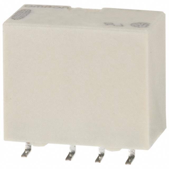
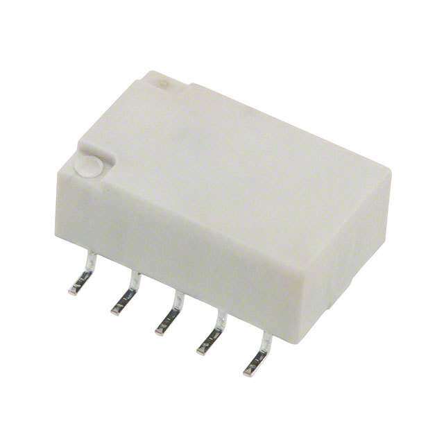
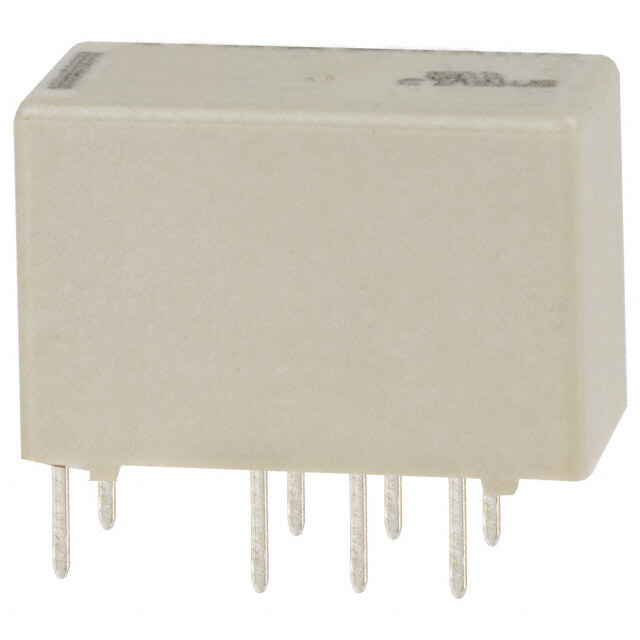
ICGOO电子元器件商城为您提供G6J-2FL-Y DC12由Omron Electronics LLC设计生产,在icgoo商城现货销售,并且可以通过原厂、代理商等渠道进行代购。 G6J-2FL-Y DC12价格参考。Omron Electronics LLCG6J-2FL-Y DC12封装/规格:信号继电器,高达 2 A, 电信 继电器 DPDT(2 Form C) 表面贴装。您可以下载G6J-2FL-Y DC12参考资料、Datasheet数据手册功能说明书,资料中有G6J-2FL-Y DC12 详细功能的应用电路图电压和使用方法及教程。
Omron Electronics Inc-EMC Div 的 G6J-2FL-Y DC12 信号继电器是一款小型、高性能的电磁继电器,额定负载为 2 A,适用于低功率控制和信号切换场景。以下是该型号的一些典型应用场景:

 1. 工业自动化
   - 设备控制:用于控制工业设备中的低功率电路,例如传感器信号的传输与切换。
   - PLC 系统:作为可编程逻辑控制器(PLC)中的信号隔离或扩展模块,实现输入/输出信号的切换。
   - 安全回路:在紧急停止或安全监控系统中,用作信号传递或断开的关键组件。

 2. 家用电器
   - 家电控制:用于冰箱、洗衣机、空调等家电中的温控器、定时器或其他低功率控制电路。
   - 照明系统:控制灯具的开关或调光功能,尤其适合需要频繁切换的小功率 LED 灯具。

 3. 汽车电子
   - 仪表盘控制:用于汽车仪表盘上的信号切换,如指示灯、报警信号等。
   - 辅助系统:在电动车窗、后视镜加热、雨刷控制系统中,实现低功率信号的切换。

 4. 医疗设备
   - 监测设备:在血压计、血糖仪等便携式医疗设备中,用于信号的隔离与切换。
   - 诊断仪器:在超声波设备、心电图机等仪器中,作为低功率信号传输的中间环节。

 5. 通信与网络设备
   - 路由器/交换机:用于电源管理或信号切换,确保网络设备的稳定运行。
   - 远程监控系统:在安防摄像头、门禁系统中,实现信号的远程控制与切换。

 6. 消费电子
   - 音频设备:用于音响、功放等设备中的音源切换或信号隔离。
   - 游戏设备:在游戏主机或外设中,实现按钮信号的切换与传输。

 特点与优势
- 小型化设计:节省空间,适合紧凑型设备。
- 高可靠性:采用优质材料,确保长期稳定运行。
- 低功耗:适合对能耗要求严格的场景。
- 耐久性:支持高频次切换,满足长时间使用需求。

综上所述,G6J-2FL-Y DC12 继电器凭借其高性能和可靠性,广泛应用于工业、家电、汽车、医疗、通信及消费电子等领域,特别适合需要低功率信号切换的场景。
| 参数 | 数值 |
| 产品目录 | |
| 描述 | RELAY TELECOM DPDT 1A 12V |
| 产品分类 | |
| 品牌 | Omron Electronics Inc-EMC Div |
| 数据手册 | |
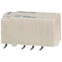
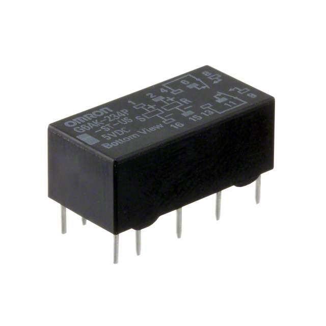
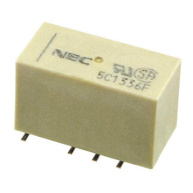
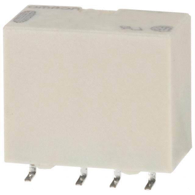
| 产品图片 |
|
| 产品型号 | G6J-2FL-Y DC12 |
| rohs | 无铅 / 符合限制有害物质指令(RoHS)规范要求 |
| 产品系列 | G6J-Y |
| 产品培训模块 | http://www.digikey.cn/PTM/IndividualPTM.page?site=cn&lang=zhs&ptm=25458 |
| 产品目录绘图 |
|
| 产品目录页面 | |
| 关闭电压(最小值) | 1.2 VDC |
| 其它名称 | G6J 3022A |
| 其它有关文件 | |
| 包装 | 管件 |
| 安装类型 | 表面贴装 |
| 导通电压(最大值) | 9 VDC |
| 工作时间 | 3ms |
| 工作温度 | -40°C ~ 85°C |
| 开关电压 | 125VAC,110VDC - 最小值 |
| 标准包装 | 50 |
| 特性 | - |
| 端子类型 | 鸥翼型 |
| 线圈功率 | 140 mW |
| 线圈电压 | 12VDC |
| 线圈电流 | 12.3mA |
| 线圈电阻 | 976.8 欧姆 |
| 线圈类型 | 无锁存 |
| 继电器类型 | 电信 |
| 触头外形 | DPDT(2 C 型) |
| 触头材料 | Silver(Ag),Gold(Au) |
| 释放时间 | 3ms |
| 额定接触(电流) | 1A |

-2(FL,FS)%20Series.jpg)
-2FL%20Series%20Footprint.jpg)
-Y%20Series%20Circuit%20Top%20View.jpg)


PDF Datasheet 数据手册内容提取
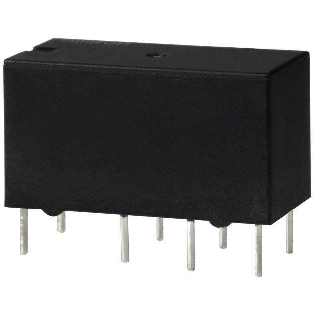
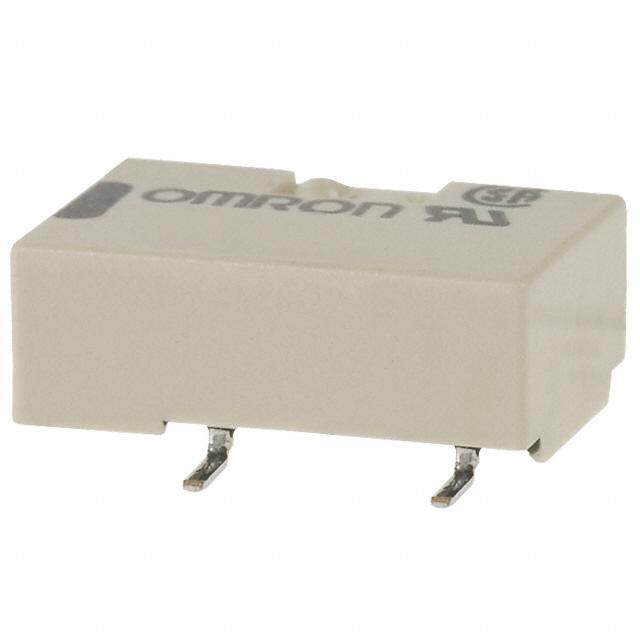
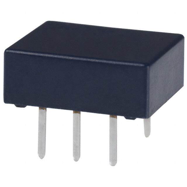
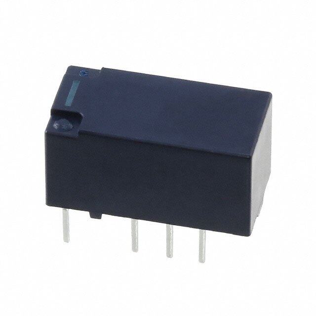
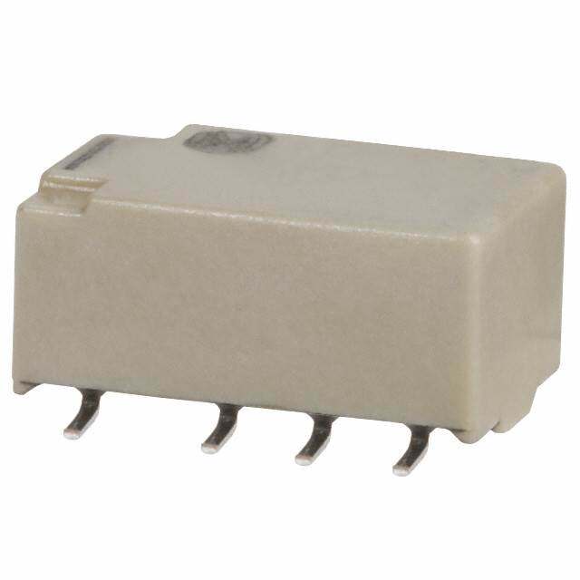
G6J-Y Surface-mounting Relay Ultra-compact and Slim DPDT Relay •Suitable for high-density mounting.(5.7 mm (W) × 10.6 mm (L) × 9mm (H)). •Dielectric strength of 1,500 VAC and an impulse withstand voltage of 2,500 V for 2 × 10 μs (conforms to Telcordia specifications (formerly Bellcore)). •Conforms to FCC Part 68 (1,500 V, 10 × 160 μs). •Single-winding latching models to save energy. •Standard models conforms to UL/C-UL standards. RoHS Compliant ■Model Number Legend ■Application Examples G6J@-@@-@ •Communication equipment 1 2 3 4 •Test & measurement equipment G 1. Relay function 3. Terminal Shape •Office automation equipment 6 None: Single-side stable relay P : PCB terminals •Audio-visual products J U : Single-winding latching relay FS: Surface-mounting terminals, short •Security equipment -Y FL: Surface-mounting terminals, long •Building automation equipment 2. Number of contact poles/ •Industrial equipment Contact form 4. Special function •Amusement equipment 2: 2-pole/DPDT (2c) Y: Improved product for soldering heat resistance ■Ordering Information Packing Tube Packing Tape Packing Minimum Protective Rated coil Minimun Rated coil Minimum ordering unit Relay Function Structure Contact form Model voltage packing unit Model voltage packing unit (tape packing) 3 VDC 3 VDC 4.5 VDC 4.5 VDC G6J-2P-Y 5 VDC − 5 VDC 12 VDC 12 VDC Single-side 24 VDC 24 VDC stable 3 VDC 3 VDC 4.5 VDC 4.5 VDC G6J-2FS-Y G6J-2FS-Y-TR 5 VDC 5 VDC G6J-2FL-Y G6J-2FL-Y-TR 12 VDC 12 VDC DPDT 800 pcs/ Fully sealed 24 VDC 50 pcs/tube 24 VDC 400 pcs/reel (2c) 2 reels 3 VDC 3 VDC 4.5 VDC 4.5 VDC G6JU-2P-Y 5 VDC − 5 VDC 12 VDC 12 VDC Single-winding 24 VDC 24 VDC latching 3 VDC 3 VDC G6JU-2FS-Y 4.5 VDC G6JU-2FS-Y-TR 4.5 VDC G6JU-2FL-Y 5 VDC G6JU-2FL-Y-TR 5 VDC 12 VDC 12 VDC Note 1.When ordering, add the rated coil voltage to the model number. Example: G6J-2P-Y DC3 Rated coil voltage However, the notation of the coil voltage on the product case as well as on the packing will be marked as @@ VDC. Note 2.When ordering tape packing, add -TR" to the model number. Be sure since -TR" is not part of the relay model number, it is not marked on the relay case. When ordering tape packing, minimum order unit is 2 reels (400 pcs ✕ 2 = 800 pcs). Note 3.Surface mounting terminal (SMT) standard models are shipped in moisture-proof package. PCB terminal standard types do not require moisture proof packaging and therefore shipped in non-moisture-proof package. 1
G6J-Y Surface-mounting Relay ■Ratings ●Coil: Single-side Stable Relays (G6J-2P-Y, G6J-2FS-Y, G6J-2FL-Y) Item Must operate voltage Must release voltage Max. voltage Rated current Coil resistance (V) (V) (V) Power consumption (mA) (Ω) (mW) Rated voltage % of rated voltage 3 VDC 48.0 62.5 4.5 VDC 32.6 137.9 Approx. 140 5 VDC 28.9 173.1 75% max. 10% min. 150% 12 VDC 12.3 976.8 24 VDC 9.2 2,600.5 Approx. 230 Note 1.The rated current and coil resistance are measured at a coil temperature of 23°C with a tolerance of ±10%. Note 2.The operating characteristics are measured at a coil temperature of 23°C. Note 3.The maximum voltage is the highest voltage that can be imposed on the Relay coil instantaneously. ●Coil: Single-winding Latching Relays (G6JU-2P-Y, G6JU-2FS-Y, G6JU-2FL-Y) Item Must set voltage Must reset voltage Max. voltage (V) (V) (V) Rated current Coil resistance Power consumption Rated voltage (mA) (Ω) % of rated voltage (mW) 3 VDC 33.7 89.0 4.5 VDC 22.0 204.3 75% max. 75% max. 150% Approx. 100 5 VDC 20.4 245.5 12 VDC 9.0 1,329.2 Note 1.The rated current and coil resistance are measured at a coil temperature of 23°C with a tolerance of ±10%. Note 2.The operating characteristics are measured at a coil temperature of 23°C. G Note 3.The maximum voltage is the highest voltage that can be imposed on the Relay coil instantaneously. 6 J ●Contacts - Y Item Load Resistive load Contact type Bifurcated crossbar Contact material Ag (Au-Alloy) 0.3 A at 125 VAC, Rated load 1 A at 30 VDC Rated carry current 1 A Max. switching voltage 125 VAC, 110 VDC Max. switching current 1 A ■Characteristics Classification Single-side stable Single-winding latching Item Model G6J-2P-Y, G6J-2FS-Y, G6J-2FL-Y G6JU-2P-Y, G6JU-2FS-Y, G6JU-2FL-Y Contact resistance *1 100 mΩ max. Operating (set) time 3 ms max. Release (reset) time 3 ms max. Min. set/reset signal width − 10 ms Insulation resistance *2 1,000 MΩ min. (at 500 VDC) Between coil and contacts 1,500 VAC, 50/60 Hz for 1 min Dielectric strength Between contacts of different polarity 1,000 VAC, 50/60 Hz for 1 min Between contacts of the same polarity 750 VAC, 50/60 Hz for 1 min Between coil and contacts 2,500 VAC, 2 × 10 μs Impulse withstand Between contacts of different polarity voltage 1,500 VAC, 10 × 160 μs Between contacts of the same polarity Destruction 10 to 55 to 10 Hz 2.5 mm single amplitude (5 mm double amplitude) Vibration resistance Malfunction 10 to 55 to 10 Hz 1.65 mm single amplitude (3.3 mm double amplitude) Destruction 1,000 m/s2 Shock resistance Malfunction 750 m/s2 Mechanical 50,000,000 operations min. (at 36,000 operations/hour) Durability Electrical 100,000 operations min. (with a rated load at 1,800 operations/hour) Failure rate (P level) (reference value) *3 10 μA at 10 mVDC Ambient operating temperature -40 to 85°C (with no icing or condensation) Ambient operating humidity 5% to 85% Weight Approx. 1.0 g Note:The above values are initial values. *1. The contact resistance was measured with 10 mA at 1 VDC with a fall-of-potential method. *2. The insulation resistance was measured with a 500 VDC Megger Tester applied to the same parts as those for checking the dielectric strength. *3. This value was measured at a switching frequency of 120 operations/min and the criterion of contact resistance is 50 Ω. This value may vary depending on the operating frequency, operating conditions, expected reliability level of the relay, etc. Always double-check relay suitability under actual load conditions. 2
G6J-Y Surface-mounting Relay ■Engineering Data ●Maximum Switching Capacity ●Durability ●Ambient Temperature vs. Maximum Voltage Switching current (A) 107531 AC resistive load 4Durability (x10 operations)1531,0000530000000 3AS10,mw8 iV0btc0iDeh Coninpt gretee rfsmarietspiqotieuvnreesan /tlhuocoryaeu:d:r 23°C Maximum voltage (%)221505000 0.7 100 0.5 DC resistive load 10 125 VAC resistive load 0.3 5 Ambient temperature: 23°C Switching frequency: 50 3 1,800 operations/hour 0.1 1 0 1 3 5 10 30 50 100 3005001,000 0 0.2 0.4 0.6 0.8 1 1.2 −40 −20 0 20 40 60 80 100 Switching voltage (V) Switching current (A) Ambient temperature (°C) Note:“Maximum voltage” is the maximum voltage that can be applied to the Relay coil. ●Ambient Temperature vs. ●Ambient Temperature vs. Must ●Shock Malfunction Switching Current Operate or Must Release Voltage Switching current (A)10000.....218642 Change rate on the basis of rated voltage (%)1098765432000000000 Maximum estimated valmamammuvveaaiinnggxx...... Sho11Xc,,00ZXk00 'd00irecXtio'ns 246800000000Y18642,00000000000Denee-rgEinzeedrgized11,,00XZ00'00 -GY6J 10 Operating voltage Y 1,000 Unit: m/s2 −040 −20 0 20 40 60 80 100 −060 −40 −20 0 20 40R elea6s0e vo8lta0g e100 ZZ' Y' SNaummpbleer: oGf 6RJe-2laPy-sY: 10 pcs Y' Ambient temperature (°C) Ambient temperature (°C) Test Conditions:Shock is applied in ±X, ±Y, and ±Z directions three times each with and without energizing the Relays to check the number of contact malfunctions. ●Electrical Durability (with Operate ●Electrical Durability ●Contact Reliability Test and Release Voltage) *1 (Contact resistance) *1 (Contact resistance) *1, *2 On the basis of rated voltage (%)108640000 SNT3S0eawu smmOiVttc pDbpchleeoCeinrrn: a gwodGt fieift t6riR hoevJ enqo-a2lsulnatP:ae y o1-gnsYpAec: ey 1rr:0ea 1 stpi,io8scnt0siv 0rea o tlepo eaordfa 5tai0ot%ns/hourmmmaianxx... ΩContact resistance (m)1,053100000000 SNTao1tf,eau 835smm0t00 0pbc %V leooe Drnp:S odCeGwfirt 6iaiwRtoJctiien-hto2hlsinanP :asy g1-/snY hAf: r oo 1erup0eqre suprieascnttsiicvoyen: lroaated NNOC mccooannxtt.aacctt ΩContact resistance (m)1,053100000000 SNTloSooppeawuaeesmmdittrrc aapbachttleoteiii oonrn1: nn god0G s fi rft /m6ariRhoeJt oeenq-Vu2 lsuaDorP:ey fC1 -ns5Y0 c:0w y1μ%i:0t Ah7 p ,ra2cen0ss 0istive NNOC mmccooaannxxtt..aacctt 50 max. 50 min. min. min. Release voltage 30 Contact resistance min. 30 Contact resistance min. 20 0 10 10 0.001 0.01 0.1 1 10 100 1,000 0.001 0.01 0.1 1 10 100 1,000 0.001 0.01 0.1 1 10 100 1,000 Operating frequency (x103 operations) Operating frequency (x103 operations) Operating frequency (x105 operations) ●Mutual Magnetic Interference ●Mutual Magnetic Interference *1. The tests were conducted at an ambient temperature of 23°C. Isntaitigael Instcaollnefdig iunr aflutiosnh Isntaitigael Instcaollnefdig iunr aflutiosnh *2. The contact resistance data are periodically %) +30 %)+30 measured reference values and are not enSeargmNizpeoledt Change rate on thebasis of initial value ( ++−−−21123000000Initial IAnsvtearlalegde i nv afluluseh SampNleot energized Change rate on thebasis of initial value (++−−−21123000000Initial IAnsvtearlalegde i nv afluluseh vCaoocaopcpolnceeunodrrteaaraistdttciii oinoftn rngnrogse m eu stbonni se evdttfhaiaeorecornr eh nctsh mewume sevi otaeancn.chltui,tti uoensarsogil n wbfogreeip lo lqe svpuruaaeerrterniyan c ttgoyio cnahn. edc k stage configuration stage configuration %) +30 %)+30 EnSeargmizpeled Change rate on thebasis of initial value ( ++−−−21123000000 Average value SampleEnergized Change rate on thebasis of initial value (++−−−21123000000 Average value Must operate voltage Must operate voltage Must release voltage Must release voltage 3
G6J-Y Surface-mounting Relay ●External Magnetic Interference (Average value) (Average value) (Average value) %) +30 %) +30 %) +30 e ( S N e ( S N e ( S N u u u al val +20 al val +20 al val +20 niti niti niti asis of i +10 asis of i +10 asis of i +10 b b b e e e n th 0 n th 0 n th 0 o o o e e e at at at e r −10 e r −10 e r −10 g g g n n n a a a h h h C C C −20 −20 −20 Sample: G6J-2P-Y Operate voltage Sample: G6J-2P-Y Operate voltage Sample: G6J-2P-Y Operate voltage −30 Number of Relays: 5 pcs Release voltage −30 Number of Relays: 5 pcs Release voltage −30 Number of Relays: 5 pcs Release voltage −1,200 −800 −400 0 400 800 1,200 −1,200 −800 −400 0 400 800 1,200 −1,200 −800 −400 0 400 800 1,200 External magnetic field (A/m) External magnetic field (A/m) External magnetic field (A/m) ●High-frequency Characteristics ●High-frequency Characteristics ●High-frequency Characteristics (Isolation) *1, *2 (Insertion Loss) *1, *2 (Return Loss, V.SWR) *1, *2 (Average value (initial)) (Average value (initial)) (Average value (initial)) G6J Isolation (dB) 1230000 2-poles Insertion Loss (dB)0.05 1-pole Return loss (dB) 12000 2-pole return loss 332..55V.SWR -Y 40 1 2-poles 30 2 1-pole return loss 50 1-pole 40 1.5 60 1.5 70 50 1 2-pole V.SWR 80 2 1-pole V.SWR 60 0.5 90 100 2.5 70 0 1 10 100 1,000 1 10 100 1,000 1 10 100 1,000 Frequency (MHz) Frequency (MHz) Frequency (MHz) ●Must Operate and Must Release ●Distribution of Bounce Time *1 ●Vibration Resistance Time Distribution *1 ber of contacts 433050 SNaummpbleer: oGf 6RJe-2laPy-sY: 30 pcs ORepleeraastee ttiimmee ber of contacts 433050 ORepleeraastee bboouunnccee ttiimmee ated value (%) 543...000 Num 25 Num 25 asis of r 21..00 e b Operate voltage 20 20 n th 0.0 o 15 15 ate −1.0 Release voltage ge r−2.0 n 10 10 a Ch−3.0 5 5 Sample: G6J-2P-Y −4.0 Number of Relays: 30 pcs −5.0 0 0.5 1 1.5 2 2.5 3 0 0.5 1 1.5 2 2.5 3 Initial After Time (ms) Time (ms) *1. The tests were conducted at an ambient temperature of 23°C. *2. High-frequency characteristics depend on the PCB to which the Relay is mounted. Always check these characteristics, including endurance, in the actual machine before use. 4
G6J-Y Surface-mounting Relay ■Dimensions (Unit: mm) PCB Terminals PCB Mounting Holes Terminal Arrangement/ G6J-2P-Y (BOTTOM VIEW) Internal Connections G6JU-2P-Y Tolerance ±0.1 mm (BOTTOM VIEW) 10.6 5.7 G6J-2P-Y Orientation mark 7.6 Eight, 0.85-dia. 5.4 holes 1 2 3 4 9 3.2 3.5 0.3 3.2 8 7 6 5 1.5 0.4 0.15 (1.5) (1.25) 3.2 3.2 G6JU-2P-Y 5.4 7.6 Note:Each value has a tolerance of ±0.3 mm. Orientation mark 1 2 3 4 S R 8 7 6 5 Note:Check carefully the coil polarity of the Relay. Surface-mounting Terminals (Short) Mounting Dimensions Terminal Arrangement/ G6J-2FS-Y (TOP VIEW) Internal Connections G6JU-2FS-Y Tolerance ±0.1 mm (TOP VIEW) G 6 G6J-2FS-Y 10.6 5.7 7.6 J 5.4 Orientation mark - Y 3.2 2.35 8 7 6 5 10.0 max. 4.35 1.5 0.4 3.2 0.8 1 2 3 4 3.2 5.7 (1.5) 5.4 G6JU-2FS-Y 7.6 Orientation mark Note 1.Each value has a tolerance of ±0.3 mm. Note 2.The coplanarity of the terminals is 0.1 mm max. 8 7 6 5 S R 1 2 3 4 Note:Check carefully the coil polarity of the Relay. Surface-mounting Terminals (Long) Mounting Dimensions Terminal Arrangement/ G6J-2FL-Y (TOP VIEW) Internal Connections G6JU-2FL-Y Tolerance ±0.1 mm (TOP VIEW) G6J-2FL-Y 7.6 10.6 5.7 Orientation mark 5.4 3.2 3.2 8 7 6 5 10.0 max. 5.2 1 2 3 4 1.5 0.4 3.2 3.2 7.4 0.8 5.4 (1.5) G6JU-2FL-Y 7.6 Orientation mark Note 1.Each value has a tolerance of ±0.3 mm. Note 2.The coplanarity of the terminals is 0.1 mm max. 8 7 6 5 S R 1 2 3 4 Note:Check carefully the coil polarity of the Relay. 5
G6J-Y Surface-mounting Relay ■Tube Packing and Tape Packing Surface mounting terminal (SMT) standard models are shipped in moisture-proof package, and PCB terminal standard types do not require moisture proof packaging and therefore shipped in non-moisture-proof package. Please refer to "Correct Use" for handling after opening moisture-proof packaging for Surface mounting terminal (SMT) models. (1)Tube Packing 2. Reel Dimensions Relays in tube packing are arranged so that the orientation mark 25.5±0.5 29.5±1 of each Relay is on the left side. 13±0.2 dia. Always confirm that the Relays are in the correct orientation 2±0.5 21±0.5 dia when mounting the Relays to the PCBs. Stopper Orientation of Relays Stopper A (gray) (green) 330 80 R1 Enlarged View of Section A Tube length: 555 mm (stopper not included) No. of Relays per tube: 50 pcs 3. Carrier Tape Dimensions (2)Tape Packing (Surface-mounting Terminal Relays) G6J-2FS-Y, G6JU-2FS-Y, G6J-2FL-Y, G6JU-2FL-Y When ordering Relays in tape packing, add the prefix “-TR” to 10.4±0.1 the model number, otherwise the Relays in tube packing will be 2±0.1 16±04.1±0.1 A B 1.5+−00.1 dia. 1.75±0.1 0.5±0.1 provided. Relays per reel: 400 pcs 1.3±0.1 13.25±0.1 G Minimum ordering unit: 2 reels (800 pcs) 24±0.2 10.8±0.1 8.4±0.1 6 1. Direction of Relay Insertion -YJ Pulling Direction B 5B°±-0B° Cross Sectio1n.1±0.1 Orientation mark A Top tape 4°±1° (cover tape) Pulling direction 9±0.1 A-A Cross Section 2.2±0.1 Carrier tape Embossed tape 6±0.1 8.3±0.1 ■Recommended Soldering Method ●IRS Method (for Surface-mounting Terminal Relays) •The thickness of cream solder to be applied should be (1) IRS Method (Mounting Solder: Lead) between 150 and 200 μm on OMRON's recommended PCB mperature (°C) •Ipthnae ot tcredorenrrr.e tcot pseorlfdoerrmin gc ocrorencdti tsioonldse brien gm, aiti nista rienceodm ams esnhdoewdn that Te Soldering 220 to 240 below on the left-hand side. Correct Soldering Incorrect Soldering 180 to 200 Relay Terminal Preheating Land 150 Heel fillet is formed PCB Solder Insufficient amount Excessive amount 90 to 120 20 to 30 of solder of solder Time (s) (The temperature profile indicates the temperature on the circuit board.) Visually check that the Relay is properly soldered. (2) IRS Method (Mounting Solder: Lead-free) C) mperature (° U(ppepawk)e: 2su5r5f°aCce m oaf xc.ase Te Soldering 250 max. 230 180 Preheating 150 Relay terminal section 120 max. 30 max. Time (s) (The temperature profile indicates the temperature on the PCB.) 6
G6J-Y Surface-mounting Relay ■Approved Standards UL/C-UL Recognized. (File No.E41515) Number of test Contact form Coil rating Contact rating operations 1 A, 30 VDC at 40°C G6J-2P-Y, 2FS-Y, 2FL-Y: 3 to 24 VDC DPDT (2c) 0.5 A, 60 VDC at 40°C 6,000 G6JU-2P-Y, 2FS-Y, 2FL-Y: 3 to 24 VDC 0.3 A, 125 VAC at 40°C ■Precautions ●Please refer to “PCB Relays Common Precautions” for correct use. Correct Use ●Long Term Current Carrying ●Mounting Latching Relays Under a long-term current carrying without switching, the Make sure that the vibration or shock that is generated from insulation resistance of the coil goes down gradually due to the other devices, such as Relays in operation, on the same panel heat generated by the coil itself. Furthermore, the contact and imposed on the Latching Relays does not exceed the rated resistance of the Relay will gradually become unstable due to the value, otherwise the Latching Relays that have been set may be generation of film on the contact surfaces. A Latching Relay can reset or vice versa. The Latching Relays are reset before be used to prevent these problems. When using a single-side shipping. If excessive vibration or shock is imposed, however, stable relay, the design of the fail-safe circuit provides protection the Latching Relays may be set accidentally. Be sure to apply a against contact failure and open coils. reset signal before use. G ●Handling of Surface-mounting Relays ●Maximum Allowable Voltage 6 •Use the Relay as soon as possible after opening the •The maximum voltage of the coil can be obtained from the coil J moistureproof package. (As a guideline, use the Relay within temperature increase and the heat-resisting temperature of -Y one week at 30°C or less and 60% RH or less.) If the Relay is coil insulating sheath material. (Exceeding the heat-resisting left for a long time after opening the moisture-proof package, temperature may result in burning or short-circuiting.) The the appearance may suffer and seal failure may occur after the maximum voltage also involves important restrictions which solder mounting process. To store the Relay after opening the include the following: moisture-proof package, place it into the original package and •Must not cause thermal changes or deterioration of the sealed the package with adhesive tape. insulating material. •When washing the product after soldering the Relay to a PCB, •Must not cause damage to other control devices. use a water-based solvent or alcohol-based solvent, and keep •Must not cause any harmful effect on people. the solvent temperature to less than 40°C. Do not put the relay •Must not cause fire. in a cold cleaning bath immediately after soldering. Therefore, be sure not to exceed the maximum voltage specified in the catalog. ●Claw Securing Force During Automatic Insertion •As a rule, the rated voltage must be applied to the coil. A During automatic insertion of Relays, make sure to set the voltage exceeding the rated value, however, can be applied to securing force of the claws to the following values so that the the coil provided that the voltage is less than the maximum Relay characteristics will be maintained. voltage. It must be noted that continuous voltage application to C the coil will cause a coil temperature increase thus affecting B A characteristics such as electrical life and resulting in the deterioration of coil insulation. ●Coating Relays mounted on PCBs may be coated or washed. Do not Direction A: 4.90 N max. apply silicone coating or detergent containing silicone, otherwise Direction B: 9.80 N max. Direction C: 9.80 N max. the silicone coating or detergent may remain on the surface of Secure the claws to the area indicated by shading. the Relays. ●Environmental Conditions During Operation, Storage, ●Other Handling and Transportation Please don’t use the relay if it suffered the dropping shock. Protect the Relays from direct sunlight and keep the Relays Because there is a possibility of something damage for initial under normal temperature, humidity, and pressure. performance. 7
G6J-Y Surface-mounting Relay G 6 J - Y (cid:129) Application examples provided in this document are for reference only. In actual applications, confirm equipment functions and safety before using the product. (cid:129) Consult your OMRON representative before using the product under conditions which are not described in the manual or applying the product to nuclear control systems, railroad systems, aviation systems, vehicles, combustion systems, medical equipment, amusement machines, safety equipment, and other systems or equipment that may have a serious influence on lives and property if used improperly. Make sure that the ratings and performance characteristics of the product provide a margin of safety for the system or equipment, and be sure to provide the system or equipment with double safety mechanisms. Note: Do not use this document to operate the Unit. OMRON Corporation Electronic and Mechanical Components Company Contact: www.omron.com/ecb Cat. No. K125-E1-08 0118(0207)(O) 8