ICGOO在线商城 > 继电器 > 信号继电器,高达 2 A > G6E-134P-US DC5
 Datasheet下载
- 型号: G6E-134P-US DC5
- 制造商: Omron Electronics LLC
- 库位|库存: xxxx|xxxx
- 要求:
| 数量阶梯 | 香港交货 | 国内含税 |
| +xxxx | $xxxx | ¥xxxx |
查看当月历史价格
查看今年历史价格
G6E-134P-US DC5产品简介:
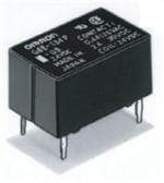
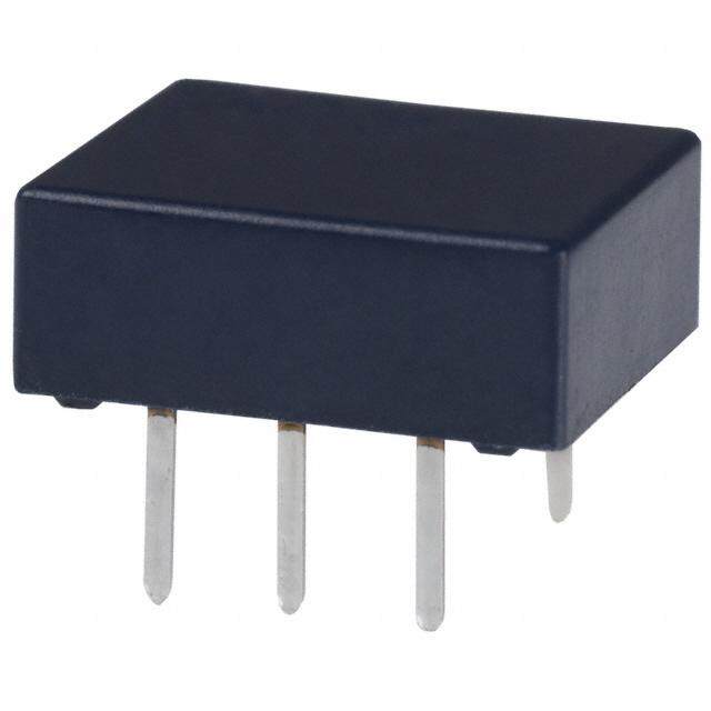
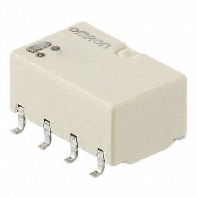
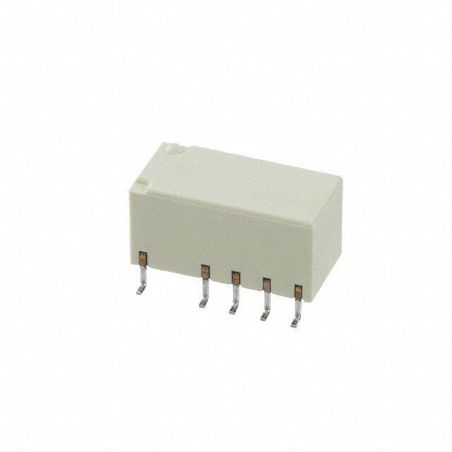
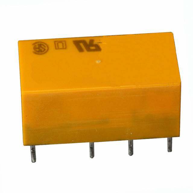
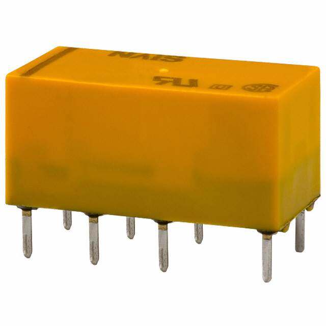
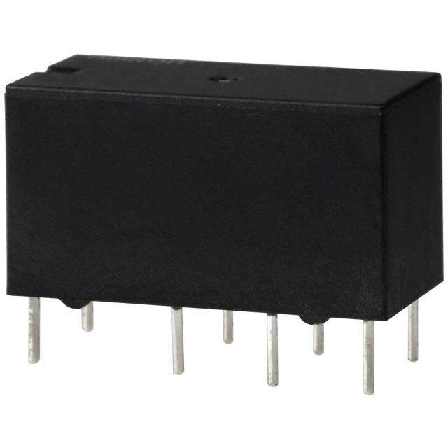
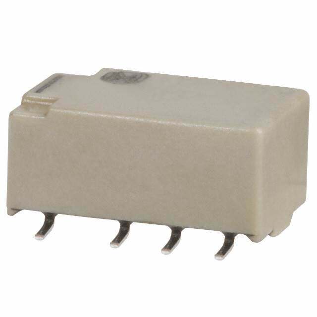
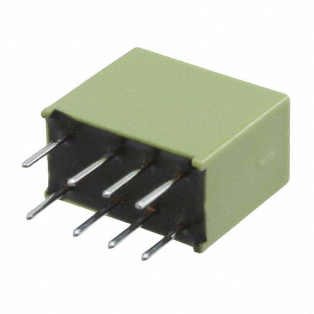
ICGOO电子元器件商城为您提供G6E-134P-US DC5由Omron Electronics LLC设计生产,在icgoo商城现货销售,并且可以通过原厂、代理商等渠道进行代购。 G6E-134P-US DC5价格参考。Omron Electronics LLCG6E-134P-US DC5封装/规格:信号继电器,高达 2 A, 通用 继电器 SPDT(1 Form C) 通孔。您可以下载G6E-134P-US DC5参考资料、Datasheet数据手册功能说明书,资料中有G6E-134P-US DC5 详细功能的应用电路图电压和使用方法及教程。
Omron Electronics Inc-EMC Div 生产的 G6E-134P-US DC5 型号信号继电器,属于小型密封继电器,额定负载高达 2 A,适用于多种工业和商业应用场景。以下是该型号的主要应用场景及特点:

 1. 工业自动化控制
   - 用途:用于工业设备中的信号切换和控制,例如 PLC(可编程逻辑控制器)、传感器接口、伺服电机控制等。
   - 特点:高可靠性、低功耗设计,能够在恶劣环境下稳定工作,适合长时间运行的工业环境。

 2. 家用电器
   - 用途:应用于家用电器的电路控制,如冰箱、空调、洗衣机等设备中的温度控制、风扇启动或停止等功能。
   - 特点:小型化设计节省空间,同时具备良好的电气性能,确保家电的安全性和稳定性。

 3. 通信设备
   - 用途:在通信设备中用于信号切换或保护电路,例如路由器、交换机或其他网络设备。
   - 特点:DC5V 驱动电压适配性广,能够满足低功耗需求,同时保证信号传输的准确性。

 4. 汽车电子
   - 用途:用于汽车电子系统中的信号控制,如车灯开关、雨刷控制、仪表盘指示灯等。
   - 特点:密封设计防止灰尘和湿气侵入,适应汽车环境中的振动和温度变化。

 5. 医疗设备
   - 用途:应用于便携式医疗设备中的信号切换,如血压计、血糖仪等。
   - 特点:小体积、低功耗,适合对空间和能耗要求较高的医疗场景。

 6. 安防系统
   - 用途:用于监控摄像头、门禁系统、报警器等安防设备的信号控制。
   - 特点:稳定的电气性能和快速响应能力,确保安防系统的可靠运行。

 总结
G6E-134P-US DC5 信号继电器凭借其紧凑的设计、高可靠性和广泛的驱动电压范围,非常适合需要低功耗、小体积和高稳定性的应用场合。无论是工业自动化、家用电器还是通信设备,该型号都能提供高效、安全的解决方案。
| 参数 | 数值 |
| 产品目录 | |
| 描述 | RELAY GENERAL PURPOSE SPDT 2A 5V低信号继电器 - PCB Relay |
| 产品分类 | |
| 品牌 | Omron Electronics |
| 产品手册 | |
| 产品图片 |
|
| rohs | 符合RoHS无铅 / 符合限制有害物质指令(RoHS)规范要求 |
| 产品系列 | 低信号继电器 - PCB,Omron Electronics G6E-134P-US DC5G6E |
| mouser_ship_limit | 该产品可能需要其他文件才能进口到中国。 |
| 数据手册 | |
| 产品型号 | G6E-134P-US DC5 |
| 产品 | Low Profile Relays |
| 产品种类 | 低信号继电器 - PCB |
| 关闭电压(最小值) | 0.5 VDC |
| 其它名称 | G6E 1079R |
| 其它有关文件 | |
| 功耗 | 200 mW |
| 包装 | 管件 |
| 商标 | Omron Electronics |
| 安装类型 | 通孔 |
| 安装风格 | Through Hole |
| 导通电压(最大值) | 3.5 VDC |
| 工作时间 | 5ms |
| 工作温度 | -40°C ~ 70°C |
| 工厂包装数量 | 25 |
| 开关电压 | 250VAC,220VDC - 最小值 |
| 最大开关电流 | 3 A |
| 标准包装 | 25 |
| 特性 | 密封式 - 全部 |
| 端子类型 | PC 引脚 |
| 端接类型 | Solder Pin |
| 类型 | Miniature |
| 系列 | G6E |
| 线圈功率 | 200 mW |
| 线圈电压 | 5 V |
| 线圈电流 | 40 mA |
| 线圈电阻 | 125 欧姆 |
| 线圈类型 | Non-Latching |
| 继电器类型 | 通用 |
| 触头外形 | SPDT(1 C 型) |
| 触头材料 | Silver(Ag),Gold(Au) |
| 触点形式 | SPDT (1 Form C) |
| 触点电流额定值 | 3 A |
| 触点额定值 | 0.4 A at 125 VAC, 2 A at 30 VDC |
| 释放时间 | 5ms |
| 零件号别名 | 422622 G6E-1011M G6E1011M G6E134PUS5DC |
| 额定接触(电流) | 2A |

,%20G6E-134P-ST-US-DC(3,5,9,12,24).jpg)


- 商务部:美国ITC正式对集成电路等产品启动337调查
- 曝三星4nm工艺存在良率问题 高通将骁龙8 Gen1或转产台积电
- 太阳诱电将投资9.5亿元在常州建新厂生产MLCC 预计2023年完工
- 英特尔发布欧洲新工厂建设计划 深化IDM 2.0 战略
- 台积电先进制程称霸业界 有大客户加持明年业绩稳了
- 达到5530亿美元!SIA预计今年全球半导体销售额将创下新高
- 英特尔拟将自动驾驶子公司Mobileye上市 估值或超500亿美元
- 三星加码芯片和SET,合并消费电子和移动部门,撤换高东真等 CEO
- 三星电子宣布重大人事变动 还合并消费电子和移动部门
- 海关总署:前11个月进口集成电路产品价值2.52万亿元 增长14.8%

PDF Datasheet 数据手册内容提取
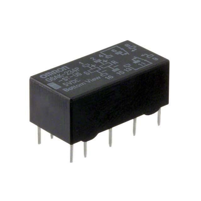
G6E Low Signal Relay Subminiature, Sensitive SPDT Signal Switching Relay •High sensitivity: 98-mW (Rated power consumption: 200mW) pickup coil power. •Impulse withstand voltage of 1,500V (10×160 μs) meets FCC requirements. •Stick packing employed in consideration of supporting automatic implementation. •Plastic-sealed model that allows automatic soldering. •New series of ultrasonically cleanable models is available. •Standard model conforms to UL/CSA standards. RoHS Compliant ■Model Number Legend ■Application Examples G6E-@-@@@@@-@-@ •Telecommunication equipment G — — — — — — — — •Office automation machines 6 1 2 3 4 5 6 7 8 •Industrial equipment E 1. Relay Function 4. Enclosure Rating 7. Approved Standards •Security equipment None: Single-side stable 4: Fully sealed US: UL, CSA U : Single-winding latching (UL: FILE No.E41515 ) 5. Terminals Shape K : Double-winding latching CSA: FILE No.LR31928 P: PCB terminals 2. Number of poles/ 8. Special Function 6. Classification None : Standard Contact Form None : Standard U : For ultrasonically 1: 1-pole/SPDT (1c) L : Low sensitivity coil cleanable 3. Contact Type (400 mW) 3: Bifurcated crossbar Ag (Au-Alloy) contact ■Ordering Information ●Standard Models (UL, CSA certified) Relay Function Single-side stable Single-winding latching Double-winding latching Classification Standard Low-sensitivity Standard Standard Low-sensitivity Minimum packing Rated coil Rated coil Rated coil Rated coil Rated coil unit Contact form Model Model Model Model Model voltage voltage voltage voltage voltage 5 VDC 5 VDC 5 VDC 5 VDC 5 VDC 6 VDC 6 VDC 6 VDC 6 VDC 6 VDC G6E 9 VDC G6E 9 VDC G6EU 9 VDC G6EK 9 VDC G6EK − SPDT (1c) -134PL-US -134P-US -134P-US -134PL-US 25 pcs/tube -134P-US 12 VDC 12 VDC 12 VDC 12 VDC 12 VDC 24 VDC 24 VDC 24 VDC 24 VDC 24 VDC 48 VDC − − − − − − − − ●Models for Ultrasonically Cleanable Relay Function Single-side stable Single-winding latching Double-winding latching Classification Standard Low-sensitivity Standard Standard Minimum packing Rated coil Rated coil Rated coil Rated coil unit Contact form Model Model Model Model voltage voltage voltage voltage 5 VDC 5 VDC 5 VDC 5 VDC 6 VDC − − − G6E 9 VDC G6E − G6EU − G6EK − SPDT (1c) -134PL-US-U -134P-US-U -134P-US-U 25 pcs/tube -134P-US-U 12 VDC 12 VDC 12 VDC 12 VDC 24 VDC 24 VDC − 24 VDC 48 VDC − − − − − − Note:When ordering, add the rated coil voltage to the model number. Example: G6E-134P-US DC5 Rated coil voltage However, the notation of the coil voltage on the product case as well as on the packing will be marked as @@ VDC. 1
G6E Low Signal Relay ■Ratings ●Coil: Single-side Stable Must operate Must release Max. Rated Coil Power voltage voltage voltage Classification Rated voltage current resistance consumption (V) (V) (V) (mA) (Ω) (mW) % of rated voltage 5 VDC 40.0 125 6 VDC 33.3 180 190% 9 VDC 22.2 405 Approx. 200 (at 23°C) Standard 12 VDC 16.7 720 70% max. 10% min. 24 VDC 8.3 2,880 170% 48 VDC 8.3 5,760 Approx. 400 (at 23°C) 5 VDC 79.4 63 6 VDC 66.6 90 170% Low-sensitivity 9 VDC 44.3 203 70% max. 10% min. Approx. 400 (at 23°C) 12 VDC 33.3 360 24 VDC 16.7 1,440 ●Coil: Single-winding latching Must set voltage Must reset voltage Max. voltage Rated current Coil resistance Power consumption Contact type Rated voltage (mA) (Ω) (V) (V) (V) % of rated voltage Set coil (mW) Reset coil (mW) 5 VDC 40.0 125 G 6 VDC 33.3 180 6 Bifurcated 9 VDC 22.2 405 70% max. 70% max. 190% Approx. 200 Approx. 200 crossbar (at 23°C) E 12 VDC 16.7 720 24 VDC 8.3 2,880 ●Coil: Double-winding latching Must set Must reset Max. Rated current (mA) Coil resistance (Ω) voltage voltage voltage Power consumption Classification Rated voltage (V) (V) (V) Set coil Reset coil Set coil Reset coil Set coil Reset coil % of rated voltage (mW) (mW) 5 VDC 40.0 40.0 125 125 6 VDC 33.3 33.3 180 180 190% Standard 9 VDC 22.2 22.2 405 405 70% max. 70% max. Approx. 200 Approx. 200 (at 23°C) 12 VDC 16.7 16.7 720 720 24 VDC 8.3 8.3 2,880 2,880 5 VDC 79.4 79.4 63 63 6 VDC 66.6 66.6 90 90 170% Low-sensitivity 9 VDC 44.3 44.3 203 203 70% max. 70% max. Approx. 400 Approx. 400 (at 23°C) 12 VDC 33.3 33.3 360 360 24 VDC 16.7 16.7 1,440 1,440 Note 1.The rated current and coil resistance are measured at a coil temperature of 23°C with a tolerance of ±10%. 2.Operating characteristics are measured at a coil temperature of 23°C. 3.The maximum voltage is the highest voltage that can be imposed on the relay coil. 4.Refer to the engineering data for relations between the ambient temperature and maximum coil voltage. ●Contacts Load Inductive load Item Resistive load (cosφ = 0.4; L/R = 7 ms) Contact type Bifurcated crossbar Contact material Ag (Au-Alloy) 0.4 A at 125 VAC; 0.2 A at 125 VAC; Rated load 2 A at 30 VDC 1 A at 30 VDC Rated carry current 3 A Max. switching voltage 250 VAC, 220 VDC Max. switching current 3 A 2
G6E Low Signal Relay ■Characteristics (Including Models for Ultrasonically Cleanable) Item Relay Function Single-side Stable Single-winding Latching Double-winding Latching Contact resistance *1 50 mΩ max. Operate (set) time 5 ms max. Release (reset) time 5 ms max. Min. set pulse width − 15 ms Min. reset pulse width − 15 ms Insulation resistance *2 1,000 MΩ min. (at 500 VDC) Impulse withstand Between coil and contacts 2,500 V (10×160 μs) (conforms to FCC part 68) voltage Between contacts of same polarity 1,500 V (10×160 μs) (conforms to FCC part 68) Between coil and contacts 1,500 VAC, 50/60 Hz for 1 min Dielectric strength Between contacts of same polarity 1,000 VAC, 50/60 Hz for 1 min Vibration Destruction 10 to 55 to 10 Hz, 2.5 mm single amplitude (5 mm double amplitude) resistance Malfunction 10 to 55 to 10 Hz, 1.65 mm single amplitude (3.3 mm double amplitude) Destruction 1,000 m/s2 Shock resistance Malfunction 300 m/s2 Mechanical 100,000,000 operations min. (at 36,000 operations/hr) 100,000 operations min. (0.4 A at 125 VAC resistive load; 0.2 A at 125 VAC inductive load) (at 1,800 operations/hr) Durability Electrical 500,000 operations min. (2 A at 30 VDC resistive load; 1 A at 30 VDC inductive load) (at 1,800 operations/hr) 200,000 operations min. (3 A at 30 VDC resistive load) (at 1,800 operations/hr) Failure rate (P level) (reference value) *3 10 μA at 10 mVDC Ambient operating temperature -40°C to 70°C (with no icing or condenstion) Ambient operating humidity 5% to 85% Weight Approx. 2.7 g Note:The values here are initial values. G *1. The contact resistance was measured with 1 A at 5 VDC using a voltage-drop method. 6 *2. The insulation resistance was measured with a 500 VDC Megger Tester applied to the same parts as those used for checking the dielectric strength. E *3. This value was measured at a switching frequency of 120 operations/min and the criterion of contact resistance is 50 Ω. This value may vary depending on the switching frequency and operating environment. Always double-check relay suitability under actual operating conditions. ■Engineering Data ●Maximum Switching Power ●Durability ●Ambient Temperature vs. Maximum Coil Voltage Switching current (A)0001...05321543 D(LC/R i n=d 7u cmtivse) load DC resAisCtiv ree sloisatdive load 4Durability (x10 operations)10531,,,,530000000000000000 3(L0/ RV D= C73 0imn VdsuD)cCti vree sloisatidve load Maximum coil voltage (%)222221864208000000 GGG666EEE-KU1--311433P44-PPU--USUSS 0.2 A(cCo sinφ d=u 0ct.i4v)e load 100125 VAC 160 GG66EE-K1-3143P4LP-LU-USS 0.1 50rloeasdistive 140 GO6nElyU a-t1 4384VPD-UCS 0.05 30 125 VAC 120 0.03 inductive load 10 (cosφ = 0.4) 100 0.01 5 0 0 3 5 10 20 30 50 100 300 500 1,000 0 0.2 0.4 1 2 3 4 -50 -40 -20 0 20 40 60 80 100 Switching voltage (V) Switching current (A) Ambient temperature (°C) Note:The maximum coil voltage refers to the maximum value in a varying range of operating power voltage, not a continuous voltage. ●Ambient Temperature vs. Must ●Shock Malfunction Operate or Must Release Voltage G6E-134P-US G6EK-134P-US On the basis of rated voltage (%)108640000 Vthoel tC1ca3ogo0ieill % ainsn o odatf p acrpaopltnpieetliddae cdwvt osittolhta ge C1H(C(RhRmm0ooooee0tiaatllll dee% sxxsi aast..ts a assovvtaraeerfaatpt r rll(vvptuuvam ooloveetieelloil))ttntaaddalt.gg a gwvveegeoai e tllaahtu att e g)e 11,,00X0000EDnee-er5gn0iez0regdized Y01,000 600 1Z,S0YYh0'o0Xck direcXt'iZZo'n 11,,00X0000 RSeeste6t00 Y01,000 700 1Z,S0YYh0'o0Xck direcXt'iZZo'n 2-0040 C10o-02il% 0is V oaofp lrpta0alti geeedd nwvoo2ittlh 0taa pgpeli4e0d to ctho6el0d c sotial ra8t n0(md icno.1 nv0taa0lc ut1es2)0 SNUaunZmmi't:p bmlee/r:s o2Gf 6REe-l1a3y4sP: 1-U0S p Yc 2s'14, 0V0D0C 1,000X' Coil terminal Contact terminal SNUaunZmmi't:p bmlee/r:s o2Gf 6REeKla-1ys3:4 2P0-U pSYc s'1 1,020 V0DC 1,000X' Coil terminal Contact terminal Ambient temperature (°C) Test Conditions: Shock is applied in ±X, ±Y, and ±Z directions three times each with and without energizing the Relays to check the number of contact malfunction. 3
G6E Low Signal Relay ●Contact Reliability Test *1, *2 ●Contact Reliability Test (70°C) *1, *2 ●Mutual Magnetic Interference G6E-134P-US G6E-134P-US G6E-134P-US %) 80 %) 80 Must operate voltage On the basis of rated voltage ( 76543210000000 MMrveouulletssaattg soeep eratSNT1Se0eaw uv smmiVottc lpDbcthaleoCeignrn: e g0odG .fift0 6riRoe1Eenq -mls1ua:3Aey R4ns Pc:e y1s-U:i0 s1S tpi,v 8mmmmc e20saaii 40nnlxxo ..Vo..apdDe Carat tions/h On the basis of rated voltage ( 76543210000000 MMSuuassmtt porelpelee: arGas6teeE vv-1oo3lltta4agPgee-US 24 VDC mmmmaaiinnxx.... dRmeet-olhteaedan5ysenes.tl0 ir sntog8h gati ezhm re eemdr 22..5544 mmmmChange rate on thebasis of initial value (%)−−2112....00000InMitiuasl ts trAaeglveeearsaeg ev ovlatTaleugseet ΩContact resistance (m)10753100000 NO co3n0ta c5t0 NC1O 0cp0oe nrtaatcint3g0 f0re 5q0u0e 1n,c0y0mmmm (0×aaiinn xx1....034 ,o0p0e0r a5ti,o0n0s0) ΩContact resistance (m)107531000000.N1NT Oeu smc0to .bc3neo t0rna .odc5tfi t i RoN1enC lsa :cy Rosn:e 3t1sa i0scSo ttp5ipwvc eeistr cal1oht0aiio ndng sa fR/trm 3e5o0qi tnVa u5tDei0onC nc1 y1(0×: 0m11 02A40 m 3 tmu0ari0nxn ..s5)00 Rmetolhtaeda5ysens.tl0 i snto8h gat ehm r eemr Change rate on thebasis of initial value (%)−−2112....00000Initial stAagveerage vaTleuset de-energized ●High-frequency Characteristics ●High-frequency Characteristics (Isolation) *1, *3 (Insertion Loss) *1, *3 G6E-134P-US (Average value (initial)) G6E-134P-US (Average value (initial)) Isolation (dB) 200 SNaummpbleer: oGf 6REe-l1a3y4sP: 5N pCc csontact Insertion loss (dB) 01 SNaummpbleer: oGf 6REe-l1a3y4sP: 5 pcs NC contact G 40 6 2 E NO contact NO contact 60 3 80 100 4 1 10 100 1,000 1 10 100 1,000 Frequency (MHz) Frequency (MHz) ●Must Operate and Must Release Time Distribution *1 G6E-134P-US G6E-134PL-US G6E-134P-US 48 VDC mber of contacts 5400 SNTcoeauismml tv pbcoleoeltrna: odgGfiet 6iR oEaenp-ls1pa:3ly i14es0Pd: 01-U%0S0 o pf cs MMuusstt orepleearastee ttiimmee mber of contacts10800 SNTcoeauismml tv pbcoleoeltrna: odgGfiet 6iR oEaen1p-ls10pa:30ly i14es0Pd: 01L%0-U0 oS pf cs MMuusstt orepleearastee ttiimmee mber of contacts 5400 S4NTco8eaui smmlV tv pDbcoleoCeltrna: odgGfiet 6iR oEaenp-ls1pa:3ly i14es0Pd: 01-U%0S0 o p f cs MMuusstt orepleearastee ttiimmee Nu Nu Nu 30 60 30 20 40 20 10 20 10 0 1.0 1.2 1.4 1.6 1.8 2.1 2.2 2.4 2.6 2.8 3.0 3.2 3.4 3.6 0 1 2 3 4 5 0 1.0 1.2 1.4 1.6 1.8 2.0 2.2 2.4 2.6 2.8 3.0 Time (ms) Time (ms) Time (ms) ●Distribution of Bounce Time *1 G6E-134P-US G6E-134PL-US mber of contacts 5400 SG1N520au6 mmEVpc-pDb1sleCe3r:4 oPf -RUeSl ays: ORepleeraastien gb obuonucnec eti mtimee mber of contacts 5400 SG1N520au6 mmEVpc-pDb1sleCe3r:4 oPf LR-UelSa ys: ORepleeraastien gb obuonucnec eti mtimee **21.. TTtehhmeep cteeorsnattstau wcrete roreefs 2ics3ota°nCndc.uec tdeadt aa ta aren paemriboideincta lly Nu Nu measured reference values and are not 30 30 values from each monitoring operation. Contact resistance values will vary according to the switching frequency and 20 20 operating environment, so be sure to check operation under the actual operating conditions before use. 10 10 *3. High-frequency characteristics depend on the PCB to which the Relay is mounted. Always check these characteristics, 0 0.1 0.2 0.3 0.4 0 0.3 0.6 0.9 1.2 1.5 1.8 2.1 including durability, in the actual machine Time (ms) Time (ms) before use. 4
G6E Low Signal Relay ■Dimensions Single-side stable PCB Mounting Holes Terminal Arrangement/ G6E-134P-US (Bottom View) Internal Connections G6E-134PL-US Tolerance: ±0.1 (Bottom View) G6E-134P-US-U 16max. 10max. 2.54 Five, 1.0 dia. holes G6E-134PL-US-U (15. 9)* (9.9)* 2.54 (1.19) 8max. 1+ −6 0.3 (7.9)* 7.62 3.5 12 10 7 Note: Be sure to confirm 0.6 0.25 coil polarity. 5.08 1.6 (1.65) 7.62 5.08 7.62 7.62 * Average value Note: Orientation marks are indicated as follows: Single-winding latching PCB Mounting Holes Terminal Arrangement/ G6EU-134P-US (Bottom View) Internal Connections G6EU-134P-US-U Tolerance: ±0.1 (Bottom View) 16max. 10max. 2.54 Five, 1.0 dia. holes (15. 9)* (9.9)* 2.54 (1.19) +1− S R −+6 8max. 0.3 (7.9)* 7.62 12 10 7 3.5 Note: Be sure to confirm coil polarity. 0.6 0.25 5.08 1.6 5.08 7.62 7.62 * Average value (1.65) 7.62 G Note: Orientation marks are indicated as follows: 6 E Double-winding latching PCB Mounting Holes Terminal Arrangement/ G6EK-134P-US (Bottom View) Internal Connections G6EK-134PL-US Tolerance: ±0.1 (Bottom View) G6EK-134P-US-U 16max. 10max. 2.54 Six, 1.0 dia. holes (15. 9)* (9.9)* 2.54 (1.19) +1 S− 3 R 6+ 8max. 0.3 (7.9)* 7.62 12 10 7 3.5 Note: Be sure to confirm coil polarity. The model G6EK-134P-1-US has positive 0.6 0.25 5.08 (+) terminal #3 and negative 1.6 (1.65) 7.62 (-) terminals #1 and #6. 5.08 7.62 7.62 * Average value Note: Orientation marks are indicated as follows: 5
G6E Low Signal Relay ■ Approved Standards •The approval rating values for overseas standards are different from the performance values determined individually. Confirm the values before use. UL recognized: (File No. E41515) CSA certified: (File No. LR31928) Contact Number of test Model Coil ratings Contact ratings form operations 0.2 A, 250 VAC SPDT 5 to 48 0.6 A, 125 VAC G6E( )-134P( )US 6,000 (1c) VDC 2 A, 30 VDC 0.6 A, 125 VDC ■Precautions ●Please refer to “PCB Relays Common Precautions” for correct use. Correct Use ●Long-term Continuously ON ●Wiring ●Relay Handling Contacts •Refer to the following diagram when •When washing the product after •Using the Relay in a circuit where the wiring to switch a DC load. The soldering the Relay to a PCB, use a Relay will be ON continuously for long difference in polarity applied to the water-based solvent or alcohol-based periods (without switching) can lead to contacts will affect the endurance of solvent, and keep the solvent unstable contacts because the heat the Relay due to the amount of contact temperature to less than 40°C. Do not G generated by the coil itself will affect movement. To extend the endurance put the Relay in a cold cleaning bath 6 E the insulation, causing a film to characteristics beyond the immediately after soldering. develop on the contact surfaces. We performance ratings, wire the common recommend using a latching relay (pin 7) terminal to the positive (+) side. (magnetic-holding relay) in this kind of 7 circuit. If a single-side stable model + 12 10 must be used in this kind of circuit, we − Load Load recommend using a fail-safe circuit design that provides protection against Wiring Diagram contact failure or coil burnout. ●Ultrasonic Cleaning ●Mounting •Do not use ultrasonic cleaning on •Do not reverse the polarity of the coil standard relay models. Doing so may (+, −). result in resonance, coil burnout, and •Provide sufficient space between contact adhesion within the Relay. Relays when mounting two or more on Use a model designed for ultrasonic the same PCB, as shown in the cleaning if ultrasonic cleaning is following diagram. required. Close mounting Distance between terminals: 2.54 × 2 (pitch) max. • Application examples provided in this document are for reference only. In actual applications, confirm equipment functions and safety before using the product. • Consult your OMRON representative before using the product under conditions which are not described in the manual or applying the product to nuclear control systems, railroad systems, aviation systems, vehicles, combustion systems, medical equipment, amusement machines, safety equipment, and other systems or equipment that may have a serious influence on lives and property if used improperly. Make sure that the ratings and performance characteristics of the product provide a margin of safety for the system or equipment, and be sure to provide the system or equipment with double safety mechanisms. Note: Do not use this document to operate the Unit. OMRON Corporation Electronic and Mechanical Components Company Contact: www.omron.com/ecb Cat. No. K024-E1-11 0617(0207)(O) 6
Mouser Electronics Authorized Distributor Click to View Pricing, Inventory, Delivery & Lifecycle Information: O mron: G6E-134P-ST-US-DC12 G6EK-134P-ST-US-DC24 G6EK-134P-ST-US-DC12 G6EK-134P-ST-US-DC5 G6E-134P- ST-US-DC9 G6E-134P-ST-US-DC5 G6E-134P-ST-US-DC24 G6E-134P-ST-US-DC6 G6E-134PL-ST-US-DC9 G6EU-134P-ST-US-DC3 G6EU-134P-ST-US-DC5 G6EU-134P-ST-US-DC6 G6EU-134P-ST-US-DC9 G6EU-134P- ST-US-DC12 G6EU-134P-ST-US-DC24 G6EK-134P-ST-US-DC3 G6EK-134P-ST-US-DC6 G6EK-134P-ST-US-DC9 G6EK-134PL-ST-US-DC3 G6EK-134PL-ST-US-DC5 G6EK-134PL-ST-US-DC6 G6EK-134PL-ST-US-DC12 G6EK- 134PL-ST-US-DC24 G6E-134PL-US DC48 G6E-134P-ST-US-H-DC48 G6EK-134P-ST-US DC1.5 G6EU-134PL-ST- US-DC12 G6EU-134PL-ST-US-DC24 G6EU-134PL-ST-US-DC5 G6E-134P-ST-US DC3 G6E-134P-ST-US-DC48 G6E-134P-US DC48 G6E-134P-US DC5 G6E-134PL-ST-US DC3 G6E-134P-US DC24 G6E-134P-US DC12 G6E- 134PL-ST-US-DC5 G6E-134PL-ST-US-DC12 G6E-134PL-ST-US-DC24 G6EK-134P-ST-1-US DC3 G6E-194P-ST-US DC12 G6EU-134P-US DC6 G6E-134P-US DC9 G6EU-134P-US DC5 G6E-134P-US DC3 G6EU-134P-US DC24