ICGOO在线商城 > 继电器 > 功率继电器,高于 2 A > G6BK-1114P-US-DC5

 Datasheet下载
- 型号: G6BK-1114P-US-DC5
- 制造商: Omron Electronics LLC
- 库位|库存: xxxx|xxxx
- 要求:
| 数量阶梯 | 香港交货 | 国内含税 |
| +xxxx | $xxxx | ¥xxxx |
查看当月历史价格
查看今年历史价格
G6BK-1114P-US-DC5产品简介:
ICGOO电子元器件商城为您提供G6BK-1114P-US-DC5由Omron Electronics LLC设计生产,在icgoo商城现货销售,并且可以通过原厂、代理商等渠道进行代购。 G6BK-1114P-US-DC5价格参考¥37.51-¥37.51。Omron Electronics LLCG6BK-1114P-US-DC5封装/规格:功率继电器,高于 2 A, 通用 继电器 SPST-NO(1 Form A) 5VDC 线圈 通孔。您可以下载G6BK-1114P-US-DC5参考资料、Datasheet数据手册功能说明书,资料中有G6BK-1114P-US-DC5 详细功能的应用电路图电压和使用方法及教程。
Omron Electronics Inc-EMC Div 的功率继电器型号 G6BK-1114P-US-DC5(额定电流高于2 A)是一种小型、高性能的电磁继电器,广泛应用于需要可靠开关和高负载能力的场景。以下是其主要应用场景:

 1. 工业自动化设备
   - 用途:用于控制电机、电磁阀、加热器等高功率负载。
   - 特点:在工业自动化系统中,该继电器可实现对不同负载的精准切换,确保设备稳定运行。

 2. 家用电器
   - 用途:应用于空调、洗衣机、冰箱等家电的电路控制。
   - 特点:能够承受较大的电流波动,保证家电在启动或运行时的安全性和可靠性。

 3. 医疗设备
   - 用途:用于医疗仪器中的电源管理或信号切换。
   - 特点:继电器的小型化设计适合紧凑型医疗设备,同时提供稳定的电气性能。

 4. 通信设备
   - 用途:在基站、路由器等通信设备中用于电源管理和信号切换。
   - 特点:支持长时间连续工作,具备良好的耐久性和抗干扰能力。

 5. 汽车电子
   - 用途:用于车载电子设备(如导航系统、车灯控制器)的电源控制。
   - 特点:适应汽车环境中的振动和温度变化,保持稳定的电气特性。

 6. 安全与监控系统
   - 用途:用于报警系统、监控摄像头等设备的电源控制。
   - 特点:能够在突发情况下快速切换电路,保障系统的正常运行。

 7. 测试与测量设备
   - 用途:在测试仪器中用于信号切换或负载控制。
   - 特点:提供精确的开关动作,满足测试设备对可靠性和精度的要求。

 总结
G6BK-1114P-US-DC5 型号的功率继电器以其高电流承载能力、长寿命和小型化设计,适用于多种需要高效、稳定电力控制的场景。无论是工业、家用还是特殊领域,该继电器都能提供可靠的解决方案。
| 参数 | 数值 |
| 产品目录 | |
| 描述 | RELAY GENERAL PURPOSE SPST 5A 5V通用继电器 SPST-NO 5VDC Double Wind Latching |
| 产品分类 | |
| 品牌 | Omron Electronics |
| 产品手册 | |
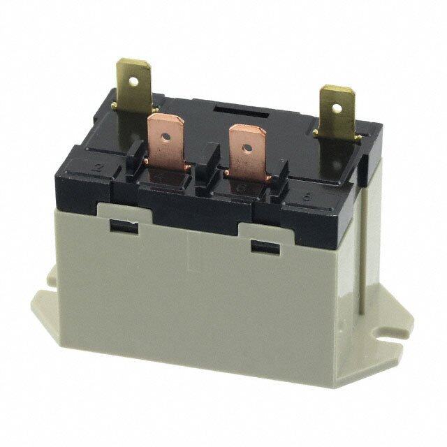
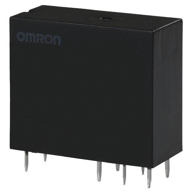
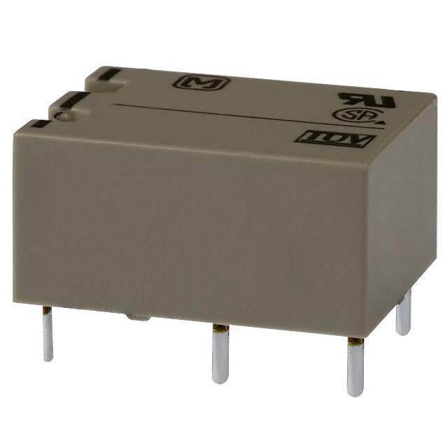
| 产品图片 |
|
| rohs | 符合RoHS无铅 / 符合限制有害物质指令(RoHS)规范要求 |
| 产品系列 | 通用继电器,Omron Electronics G6BK-1114P-US-DC5G6B |
| mouser_ship_limit | 该产品可能需要其他文件才能进口到中国。 |
| 数据手册 | |
| 产品型号 | G6BK-1114P-US-DC5 |
| 产品 | Low Profile Relays |
| 产品培训模块 | http://www.digikey.cn/PTM/IndividualPTM.page?site=cn&lang=zhs&ptm=25458 |
| 产品目录页面 | |
| 产品种类 | 通用继电器 |
| 关闭电压(最小值) | - |
| 其它名称 | G6BK-1114P-US-DC5-ND |
| 其它有关文件 | |
| 切换电压 | 380 VAC, 125 VDC |
| 功耗 | 0.28 W |
| 包装 | 散装 |
| 商标 | Omron Electronics |
| 安装类型 | 通孔 |
| 安装风格 | Through Hole |
| 宽度 | 10 mm |
| 导通电压(最大值) | 3.5 VDC |
| 工作时间 | 10ms |
| 工作温度 | -25°C ~ 70°C |
| 工厂包装数量 | 100 |
| 开关电压 | 380VAC,125VDC - 最小值 |
| 最大开关电流 | 5 A |
| 标准包装 | 100 |
| 特性 | 密封式 - 全部 |
| 相关产品 | /product-detail/zh/P6B-Y1/P6B-Y1-ND/1828743/product-detail/zh/P6B-C2/Z3635-ND/1828742/product-detail/zh/P6B-06P/P6B-06P-ND/1828741 |
| 端子类型 | PC 引脚 |
| 端接类型 | Solder Pin |
| 类型 | Miniature |
| 系列 | G6B |
| 线圈功率 | 280 mW |
| 线圈电压 | 5 VDC |
| 线圈电流 | 56 mA |
| 线圈电阻 | 89.2 Ohms |
| 线圈类型 | Dual Coil Latching |
| 继电器类型 | 通用 |
| 触头外形 | SPST-NO(1 A 型) |
| 触头材料 | 银合金,无镉 |
| 触点形式 | SPST (1 Form A) |
| 触点材料 | Silver Alloy |
| 触点电流额定值 | 5 A |
| 触点端接 | PCB |
| 释放时间 | 10ms |
| 长度 | 20 mm |
| 零件号别名 | 375081 G6BK1114PUS5DC G6BK1114PUSDC5NC |
| 额定接触(电流) | 5A |
| 高度 | 10 mm |


- 商务部:美国ITC正式对集成电路等产品启动337调查
- 曝三星4nm工艺存在良率问题 高通将骁龙8 Gen1或转产台积电
- 太阳诱电将投资9.5亿元在常州建新厂生产MLCC 预计2023年完工
- 英特尔发布欧洲新工厂建设计划 深化IDM 2.0 战略
- 台积电先进制程称霸业界 有大客户加持明年业绩稳了
- 达到5530亿美元!SIA预计今年全球半导体销售额将创下新高
- 英特尔拟将自动驾驶子公司Mobileye上市 估值或超500亿美元
- 三星加码芯片和SET,合并消费电子和移动部门,撤换高东真等 CEO
- 三星电子宣布重大人事变动 还合并消费电子和移动部门
- 海关总署:前11个月进口集成电路产品价值2.52万亿元 增长14.8%

PDF Datasheet 数据手册内容提取
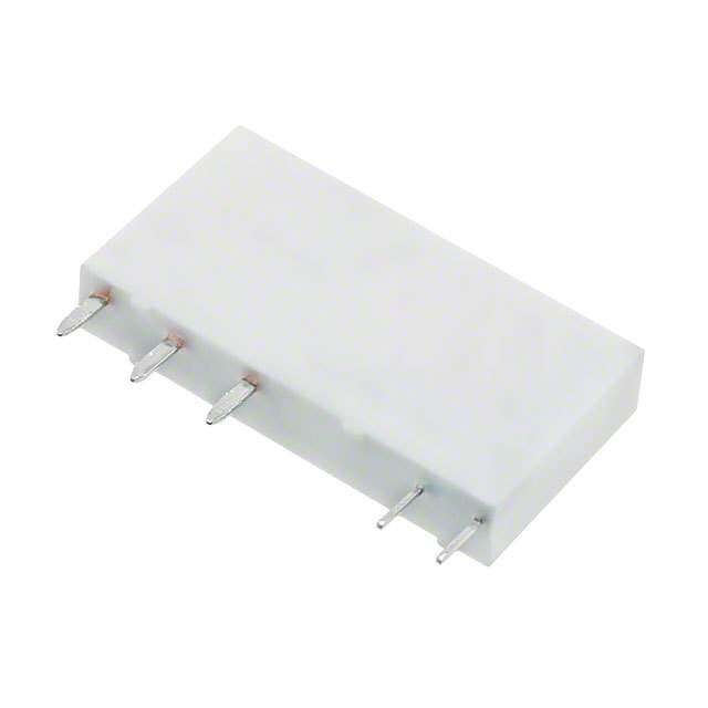
G6B PCB Power Relay High Capacity and High Dielectric Strength Miniature Relay with Fully Sealed Construction in 5 A (8 A) SPST-NO(1a), SPST-NO+SPST-NC(1a1b), DPST-NO(2a), DPST-NC(2b) Types •P6B model for connecting sockets are available. •High insulation with dielectric strength of 3,000VAC between coil and contacts (impulse withstand voltage of 6 kV). G •Standard model conforms to UL/CSA standards. 6 B •AgSnIn contacts suitable for loads that generate surge voltage (inductive load, capacity load, etc.) are available. (-FD type) •Ultrasonic cleanable models are available. (-U type) •Operation indicator & built-in surge absorption diode models are available. (-ND type) •2-Pole type available. •High-reliability models are available. G6B-1184P-US model (The relay used in Terminal Relay G6B-48BND) ■Application Examples RoHS Compliant •Ideal for output applications of control equipments ■Model Number Legend G6B@-@@@@@-@--@-@-@-@-@ 1 2 3 4 5 6 7 8 9 10 11 1. Relay Function 4. Enclosure rating 8. Operation Indicator Diode None: Single-side stable 4: Fully sealed Availability U : Single-winding latching 7: Flux protection None: Standard (G6B@-1114 models only) ND : Operation indicator & coil surge 5. Terminal Shape K : Double-winding latching absorption diode P: Straight PCB terminals (G6B@-1114 models only) (for -1177 type only) Socket mounting terminals 2. Contact Form C: Self-clinching PCB 9. Approved Standards 21: SPST-NO + SPST-NC US: UL/CSA 6. Contact material 22: DPST-NO None: Standard (Ag-alloy (Cd free)) 10. Washability 20: DPST-NC FD : AgSnIn contact None: Standard 11: SPST-NO (Suitable for DC inductive load with U : For ultrasonically cleanable 3. Classification high inrush current) 11. Mounting 1: Standard 7. Coil Polarity None: Mounted directly to PCB 7: High-capacity None: 5, 6 Terminal (+), 1, 2 Terminal (-) P6B: Mounted to Socket 8: Single crossbar 1 : 5, 6 Terminal (-), 1, 2 Terminal (+) 1
G6B PCB Power Relay ■Ordering Information ●Standard Models (UL, CSA certified) Number Contact material Standard (Ag-alloy (Cd free)) AgSnIn contact Minimum of poles Relay Function Contact form Terminals Model Rated coil voltage Model Rated coil voltagepacking unit Straight PCB G6B-1114P-US 5, 6, 12, 24 VDC G6B-1114P-FD-US 5, 6, 12, 24 VDC SPST-NO (1a) 100 (Standard) Self-clinching G6B-1114C-US 5, 6, 12, 24 VDC G6B-1114C-FD-US 12, 24 VDC pcs/tray PCB Straight PCB G6B-1174P-US 5, 6, 12, 24 VDC G6B-1174P-FD-US 5, 6, 12, 24 VDC Single-side SPST-NO (1a) 20 stable (High-capacity) Self-clinching G6B-1174C-US 5, 12, 24 VDC G6B-1174C-FD-US 5, 12, 24 VDC pcs/tube PCB Straight PCB G6B-1184P-US 5, 12, 24 VDC --- --- SPST-NO (1a) (High-reliability ) Self-clinching --- --- --- --- PCB 1-pole Straight PCB G6BU-1114P-US 5, 6, 12, 24 VDC G6BU-1114P-FD-US 5, 12, 24 VDC Single-winding SPST-NO (1a) latching (Standard) Self-clinching G6BU-1114C-US 12 VDC --- --- PCB Straight PCB G6BK-1114P-US 5, 6, 12, 24 VDC G6BK-1114P-FD-US 5, 6, 12, 24 VDC Double-winding SPST-NO (1a) latching (Standard) Self-clinching G6BK-1114C-US 5, 6, 12, 24 VDC G6BK-1114C-FD-US 24 VDC PCB SPST-NO (1a) Straight PCB G6B-1177P-ND-US 5, 12, 24 VDC G6B-1177P-FD-ND-US 5, 12, 24 VDC Single-side (Built-in high- 100 stable capacity operation Self-clinching G6B-1177C-ND-US 5, 12, 24 VDC G6B-1177C-FD-ND-US 12, 24 VDC pcs/tray indicator & diode) PCB G SPST-NO (1a)+ Straight PCB G6B-2114P-US 5, 6, 12, 24 VDC G6B-2114P-FD-US 5, 6, 12, 24 VDC 6 SPST-NC (1b) Self-clinching B (Standard) PCB G6B-2114C-US 5, 12, 24 VDC G6B-2114C-FD-US 5, 12 VDC Straight PCB G6B-2214P-US 5, 6, 12, 24 VDC G6B-2214P-FD-US 5, 6, 12, 24 VDC Single-side DPST-NO (2a) 2-pole stable (Standard) Self-clinching G6B-2214C-US 5, 12, 24 VDC G6B-2214C-FD-US 5, 12, 24 VDC PCB Straight PCB G6B-2014P-US 5, 6, 12, 24 VDC G6B-2014P-FD-US 5, 6, 12, 24 VDC DPST-NC (2b) (Standard) Self-clinching G6B-2014C-US 5, 6, 12, 24 VDC G6B-2014C-FD-US 12, 24 VDC PCB Note:AgSnIn contact models are highly welding-resistant, and roughening of contacts due to inrush current and inductive load is lessened. ●Models for Reverse Coil Polarity Number Contact material Standard (Ag-alloy (Cd free)) AgSnIn contact Minimum of poles Relay Function Contact form Terminals Model Rated coil voltage Model Rated coil voltagepacking unit Straight PCB G6B-1114P-1-US 5, 6, 12, 24 VDC G6B-1114P-FD-1-US 24 VDC SPST-NO (1a) 100 (Standard) Self-clinching --- --- --- --- pcs/tray Single-side PCB stable Straight PCB G6B-1174P-1-US 5, 12, 24 VDC --- --- SPST-NO (1a) 20 (High-capacity) Self-clinching --- --- --- --- pcs/tube PCB 1-pole Straight PCB G6BU-1114P-1-US 5, 12 VDC --- --- Single-winding SPST-NO (1a) latching (Standard) Self-clinching --- --- --- --- PCB Straight PCB G6BK-1114P-1-US 5, 6, 12, 24 VDC --- --- Double-winding SPST-NO (1a) latching (Standard) Self-clinching --- --- --- --- PCB 100 SPST-NO (1a)+ Straight PCB G6B-2114P-1-US 5, 6, 12, 24 VDC G6B-2114P-FD-1-US 12, 24 VDC pcs/tray SPST-NC (1b) Self-clinching Single-side (Standard) PCB --- --- --- --- 2-pole stable Straight PCB G6B-2214P-1-US 5, 12, 24 VDC --- --- DPST-NO (2a) (Standard) Self-clinching --- --- --- --- PCB Note:AgSnIn contact models are highly welding-resistant, and roughening of contacts due to inrush current and inductive load is lessened. 2
G6B PCB Power Relay ●Models for Ultrasonically Cleanable Number Contact material Standard (Ag-alloy (Cd free)) AgSnIn contact Minimum of poles Relay Function Contact form Terminals Model Rated coil voltage Model Rated coil voltagepacking unit Straight PCB G6B-1114P-US-U 5, 6, 12, 24 VDC G6B-1114P-FD-US-U 6, 12, 24 VDC Single-side SPST-NO (1a) stable (Standard) Self-clinching G6B-1114C-US-U 5, 12, 24 VDC --- --- PCB Straight PCB G6BU-1114P-US-U 24 VDC --- --- Single-winding SPST-NO (1a) 1-pole latching (Standard) Self-clinching --- --- --- --- PCB Straight PCB G6BK-1114P-US-U 5, 6, 12, 24 VDC G6BK-1114P-FD-US-U 12, 24 VDC Double-winding SPST-NO (1a) latching (Standard) Self-clinching G6BK-1114C-US-U 24 VDC --- --- PCB 100 SPST-NO (1a)+ Straight PCB G6B-2114P-US-U 5, 12, 24 VDC G6B-2114P-FD-US-U 5, 12, 24 VDC pcs/tray SPST-NC (1b) Self-clinching (Standard) PCB --- --- --- --- Straight PCB G6B-2214P-US-U 5, 6, 12, 24 VDC G6B-2214P-FD-US-U 5, 12, 24 VDC Single-side DPST-NO (2a) 2-pole stable (Standard) Self-clinching G6B-2214C-US-U 12, 24 VDC --- --- PCB Straight PCB G6B-2014P-US-U 5, 12, 24 VDC G6B-2014P-FD-US-U 5, 12, 24 VDC DPST-NC (2b) (Standard) Self-clinching --- --- --- --- PCB Note:When ordering, add the rated coil voltage to the model number. Example: G6B-1114P-US DC5 Rated coil voltage G However, the notation of the coil voltage on the product case as well as on the packing will be marked as @@ VDC. 6 B ●Connecting Sockets (Sold Separately) Applicable relay Model Minimum ordering unit G6B-1114P(-FD)-US-P6B G6B-1174P(-FD)-US-P6B P6B-04P G6B-1177P(-FD)-ND-US-P6B G6BU-1114P-US-P6B 20 pcs G6BK-1114P-US-P6B P6B-06P G6B-2114P-US-P6B G6B-2214P-US-P6B P6B-26P G6B-2014P-US-P6B Removal Tool P6B-Y1 1 pcs Hold-down Clips P6B-C2 Note 1.G6B-1174P-US-P6B and G6B-1177P-ND-US-P6B are rated for 8 A when mounted on a PCB. However, when used with the P6B-04P socket models, the allowable current is derated to 5 A. 2.The P6B sockets are designed to be used with G6B-@@@@P(-FD)-US-P6B relays. Only use G6B relays that include "-P6B" in their model numbers with the sockets. Do not use standard G6B's that omit "-P6B" from their model numbers with the sockets. 3.The hold-down clips of the P6B-C2 model are not suitable for the G6B-1174P and G6B-1177P models since they have different heights. 4.Products with UL/CSA certification marks will be supplied for orders of standard models. 3
G6B PCB Power Relay ■Ratings ●Coil: 1-Pole, Single-side Stable Type (Including models for ultrasonically cleanable) Item Must operate Must release Max. voltage Rated current Coil resistance Power consumption voltage (V) voltage (V) (V) (mA) (Ω) (mW) Rated voltage % of rated voltage 5 VDC 40 125 6 VDC 33.3 180 160% 70% max. 10% min. Approx. 200 12 VDC 16.7 720 (at 23°C) 24 VDC 8.3 2,880 ●Coil: 2-Pole, Single-side Stable Type (Including models for ultrasonically cleanable) Item Must operate Must release Max. voltage Rated current Coil resistance Power consumption voltage (V) voltage (V) (V) (mA) (Ω) (mW) Rated voltage % of rated voltage 5 VDC 60 83.3 6 VDC 50 120 140% 80% max. 10% min. Approx. 300 12 VDC 25 480 (at 23°C) 24 VDC 12.5 1,920 ●Coil: Single-winding Latching Type (Including models for ultrasonically cleanable) Item Must set Must reset Max. voltage Rated Coil Power consumption voltage (V) voltage (V) (V) current resistance (mA) (Ω) % of rated voltage Set coil Reset coil Rated voltage (mW) (mW) G 5 VDC 40 125 6 6 VDC 33.3 180 160% B 12 VDC 16.7 720 70% max. 70% max. (at 23°C) 200 200 24 VDC 8.3 2,880 ●Coil: Double-winding Latching Type (Including models for ultrasonically cleanable) Item Rated current (mA) Coil resistance (Ω) Must set voltage Must reset voltageMax. voltage Power consumption (V) (V) (V) Set coil Reset coil Rated voltage Set coil Reset coil Set coil Reset coil % of rated voltage (mW) (mW) 5 VDC 56 56 89.2 89.2 6 VDC 46.8 46.8 128.5 128.5 130% 70% max. 70% max. 280 280 12 VDC 23.3 23.3 515 515 (at 23°C) 24 VDC 11.7 11.7 2,060 2,060 ●Coil: Operation Indicator Model (Flux-resistant type. Do not wash down with water.) Item Must operate Must release Max. voltage Rated current Coil resistance Power consumption voltage (V) voltage (V) (V) (mA) (Ω) (mW) Rated voltage % of rated voltage 5 VDC 43 116 Approx. 200 130% 12 VDC 19.7 610 70% max. 10% min. Approx. 240 (at 23°C) 24 VDC 11.3 2,120 Approx. 275 Note 1.The rated current and coil resistance are measured at a coil temperature of 23°C with a tolerance of ±10%. 2.The operating characteristics are measured at a coil temperature of 23°C. 3.The “Max. voltage” is the maximum voltage that can be applied to the relay coil. ●Contacts G6B-1114P(-FD)(-1)-US G6B-2114P(-FD)(-1)-US G6BU-1114P(-FD)(-1)-US G6B-1174P(-FD)(-1)-US G6B-2214P(-FD)(-1)-US G6BK-1114P(-FD)(-1)-US G6B-1177P(-FD)-ND-US G6B-2014P(-FD)-US Model G6B-1184P-US G6B-1114C(-FD)-US G6B-1174C(-FD)-US G6B-2114C(-FD)-US G6BU-1114C-US G6B-1177C(-FD)-ND-US G6B-2214C(-FD)-US G6BK-1114C(-FD)-US G6B-2014C(-FD)-US Load Inductive load Inductive load Inductive load Inductive load Item Resistive load (cosφ = 0.4; L/R = 7 ms) Resistive load (cosφ = 0.4; L/R = 7 ms) Resistive load (cosφ = 0.4; L/R = 7 ms) Resistive load (cosφ = 0.4; L/R = 7 ms) Contact type Single Single crossbar Single Contact material Ag-Alloy (Cd free) Au-alloy + Ag (Cd free) Ag-Alloy (Cd free) 5 A (3 A) at 250 VAC 2 A (2 A) at 250 VAC 8 A (5 A) at 250 VAC 2 A (2 A) at 250 VAC 2 A at 250 VAC 0.5 A at 250 VAC 5 A (3 A) at 250 VAC 1.5 A (1.5 A) at 250 VAC Rated load 5 A (3 A) at 30 VDC 2 A (2 A) at 30 VDC 8 A (5 A) at 30 VDC 2 A (2 A) at 30 VDC 2 A at 30 VDC 0.5 A at 30 VDC 5 A (3 A) at 30 VDC 1.5 A (1.5 A) at 30 VDC Rated carry current 5 A (5 A) 8 A (5 A) 2A 5 A (5 A) Max. switching voltage 380 VAC, 125 VDC Max. switching current 5 A (5 A) 8 A (5 A) 2A 5 A (5 A) Note 1.The values in the parentheses ( ) are for -FD models only. 2.Use the -FD type for inductive load and switching load which contact roughening is small. 4
G6B PCB Power Relay ■Characteristics G6B-2114P(-FD)(-1)-US G6B-1114P(-FD)(-1)-US G6B-2214P(-FD)(-1)-US G6B-1174P(-FD)(-1)-US G6BU-1114P(-FD)(-1)-US G6BK-1114P(-FD)(-1)-US G6B-1177P(-FD)-ND-US G6B-2014P(-FD)(-1)-US Model G6B-1184P-US G6B-1114C(-FD)-US G6BU-1114C-US G6BK-1114C(-FD)-US G6B-1177C(-FD)-ND-US G6B-2114C(-FD)-US G6B-1174C(-FD)-US G6B-2214C(-FD)-US G6B-2014C(-FD)-US Single-winding Double-winding Built-in operation indicator Item Classification Single-side stable Single-side stable Single-side stable latching latching & surge absorption diode Contact resistance *1 30 mΩ max. 50 mΩ max. 30 mΩ max. Operate (set) time 10 ms max. Release (reset) time 10 ms max. Min. set pulse width − 15 ms (at 23°C) − Min. reset pulse width − 15 ms (at 23°C) − Insulation resistance *2 1,000 MΩ min. Between coil and 2,000 VAC, 3,000 VAC, 50/60 Hz for 1 min 3,000 VAC, 50/60 Hz for 1 min contacts 50/60 Hz for 1 min Between contacts 1,000 VAC, 50/60 Hz for 1 min Dielectric of the same polarity strength Between contacts − 2,000 VAC, of different polarity 50/60 Hz for 1 min Between set and − 250 VAC, − reset coils 50/60 Hz for 1 min Impulse withstand voltage 6 kV 1.2 × 50 μs 4.5 kV 1.2 × 50 μs 6 kV 1.2 × 50 μs − 6 kV 1.2 × 50 μs (between coil and contacts) Vibration Destruction 10 to 55 to 10 Hz, 0.75 mm single amplitude (1.5 mm double amplitude) resistance Malfunction 10 to 55 to 10 Hz, 0.75 mm single amplitude (1.5 mm double amplitude) Shock Destruction 1,000 m/s2 G resistance Malfunction 100 m/s2 300 m/s2 100 m/s2 6 Mechanical 50,000,000 operations min. (at 18,000 operations/hr) Durability B Electrical 100,000 operation min. (at 1,800 operations/hr under rated load) Failure rate (P level) 10 mA at 5 VDC 1 mA at 1 VDC 10 mA at 5 VDC (reference value) *3 Ambient operating temperature -25°C to 70°C (with no icing or condensation) Ambient operating humidity 5% to 85% Weight Approx. 3.5 to 4.6 g Approx. 3.5 g Approx. 3.7 g Approx. 5.4 g Approx. 3.5 g Approx. 4.5 g Note 1.The values here are initial values. 2.The G6B-1177P(-FD)-ND model is flux-resistant. Do not wash it down with water. *1. The contact resistance was measured with 1 A at 5 VDC using a voltage-drop method. *2. Measurement conditions: The insulation resistance was measured with a 500 VDC megohmmeter at the same locations as the dielectric strength was measured.(Except the location between set/reset coil) *3. This value was measured at a switching frequency of 120 operations/min. 5
G6B PCB Power Relay ■Engineering Data ●Maximum Switching Current G6B-2114P-US G6B-1114P-US G6B-1174P-US G6B-2214P-US G6B-1174P-FD-US G6B-2014P-US Switching current (A) 42100053 ACA C resistive load Switching current (A)10531000085 AC resistive load Switching current (A)1053100005 GGG666BBB---222120111444PPP---FFFDDD---UUUSSS A(cCo sinφ dAl=ou Ca0cd t.ri4ve)es ilsotaivde 2 inductive 3 3 1 D(LC/R i n=d 7u cmtivse) load lcooasdφ = 0.4 2 DC resistive load AC 1.25 1 inductive 1 AC 0.5 DC resistive load 0.5 load 0.5 DC resistive load rloeasdistive 0.3 DC inductive load 0.3 0.3 0.2 DC inductive load (L/R = 7 ms) 0.1 0.1 0.1 0 3 5 10 20 30 100 300 500 0 3 5 10 30 50 100 380 1,000 0 3 5 10 30 50 100 300 500 1,000 Switching voltage (V) Switching voltage (V) Switching voltage (V) ●Ambient Temperature vs. ●Durability Maximum Coil Voltage G6B-1114P-US G6B-2114P(-FD)-US G6B-1114P-US G6B-2114P-US G6B-1174P-US G6B-2214P(-FD)-US G6B-1174P-US G6B-2214P-US G6B-1174P-FD-US G6B-2014P(-FD)-US G6B-1174P-FD-US G6B-2014P-US GB6 4Durability (x10 operations)1,5310000530000000 G2G256506B0 BV- 1V-A11AC11C74/34/P30P-0 UV- FVSDDDC-CG2rU er5 eS6rs0esBis siVs-ti1istvAi1tveiC7ve le4/ o3l oPal0oa-d UadVdSDC 4Durability (x10 operations)1,5310000530000000 GGG2(c5666o0BBBs φV---222 A=120 C1110444/.34PPP0, ((( L---VFFFGGG2/RD5DDD6660 C)))BBB=--- VUUU--- i7222nASSS 120dmC111us444/c3)tPPPi0v--- eUUUV SSSDloCad resistive load Maximum coil voltage (%)211110864300000 GGG666BBB---111111177444PPP---UUFDSS-US 120 110 10 10 Higher 100 G6B-2114P-US 5G6B-1114P-US capacity 5 G6B-2114P-FD-US G6B-2214P-US G6B-1174P-FD-US G6B-2214P-FD-US G6B-2014P-US 3G6B-1174P-US 3 G6B-2014P-FD-US 80 250 VAC/30 VDC inductive load 250 VAC resistive load (cosφ = 0.4, L/R = 7 ms) 1 1 60 0 1 2 3 4 5 6 7 8 9 10 0 1 1.5 2 3 4 5 6 7 8 9 10 0 20 23 30 40 50 60 70 80 90 Switching current (A) Switching current (A) Ambient temperature (°C) Note:The maximum coil voltage refers to the maxi-mum value in a varying range of operating power voltage, not a continuous voltage. ●Ambient Temperature vs. Must ●Mutual Magnetic Interference Operate and Must Release Voltage G6B-1114P-US G6B-1114P-US G6B-1114P-US Must-operate/must-release voltage (%)108642−00000040SGN au6mmB-pb1l−ee12r:1 0o4 fP R-UelSay0s : 5 pcs20 AmbMMieuu4nss0ttt toreepmleeparaest6erea0 mvmtmvm uooaariilnlnetxtxaa.. ..XX(gg°e8eC0) De-EeSnnaeemrrggpii2lzze.ee5dd4 mmSample Change rate on theChange rate on thebasis of initial value (%)basis of initial value (%) +++−−+−−10011001........0505005050IInnMMiittiiuuaassll ttss ttoraaAAepgglvveeeeeeararrsaateegg eevv oovvllaatTTtaalleeuuggsseeeett 2.5S4aS mmampmlpele De-EenneerrggiizzeeddChange rate on theChange rate on thebasis of initial value (%)basis of initial value (%)+++−−+−−10011001........0505005050IInnMMiittiiuuaassll ttss ttoraaAAepgglvveeeeeeararrsaateegg eevv oovvllaatTTtaalleeuuggsseeeett 6
G6B PCB Power Relay ●Shock Malfunction Y Y Y 1,000 1,000 Reset Energized Energized Set 300 X Z X Z X Z 400 1,000 1,000 1,000 1,000 100 300 600 700 200 200 100 300 400 1,000 1,000 1,000 1,000 Z' X' Z' X' Z' X' 300 Unit: m/s2 1,000 Unit: m/s2 1,000 Unit: m/s2 Y' Y' Y' Sample: G6B-1114P-US Sample: G6B-1174P-US Sample: G6BK-1114P-US Number of Relays: 12 pcs G6B-1174P-FD-US Number of Relays: 12 pcs Test Conditions: Shock is applied in ±X, ±Y, Test Conditions: Shock is applied in ±X, ±Y, Test Conditions: The value at which and ±Z directions three times each with without and ±Z directions three times each with without malfunction occurred was measured after etmRmoneaa ecqllffhruuugeincirczetckiiontm itonghen e1ntsh 0t.n:e0 uN Rmmoenb/lsaee2y r so f Y XShock directionX' ZZ' etmRmoneaa ecqllffhruuugeincirczetcikiontm iontghen 1entsh0 t.n:e0 uN Rmmoen/blsaee2y r so f Y XShock directionX' ZZ' atiaSnepxt sae6ptns lypdd.iiinaeregrcdc est ivho3aon ltucsimke a :et loos ntehgae c3 h Y XShock directionX' ZZ' Y' (Coil) Y' (Coil) 300 m/s2 Y' (Coil) ●Hot Start Rate of variability (%) 432000S NTbvch ooao eau lnsu smmt aettr a: pbgd ect lee h eato r e :cic n so hGGu v fc ar a6u6roRperBnBlipedand--ll 11ttieasie 1o1(rytd5a 1n7sd Ar4 4:tito of) PP1fa,f e 0t--taohrUF e2nppeDSn3dec c-t°s r UloaCeitSfl,i t nw d fg ouit rrhv ion 1rlg ata twegdhe i cish mraetaesdu red Rate of variability (%) 432000 STbvceteouaaeamlrscsmtraehtpe:pgd enutle hreton a e:(ind t8s Gu ev Acarar6eo) pr,Bdsl ipdaai.-fl 1tfnisiee1odtdra7n e lr4 etntoo Pftaft t-atofhU om2peSr3e bc1°rioaeC hitnl,io ntwd uguirt rhvion rlgata twegdhe i ccisoh n mrtaaetcaetsd u red Rate of variability (%) 432000 S Tmwcf oo eahe rn s mia 1ctt a:s h p huct lh erotr a ee :uc td GGGreuv drea666br aerBBBavicanso---h222tetli t 201od(au5111n gnoA444 edon)PPP e,f i sc---raoUUU odanpSSiSlipde fcfp relaoelritlefeditnd n gs tt t oav ortthl taaetg c2eo3 ii°ls Cw ,i tdhu rraintegd GB6 ambient ambient temperatures. temperatures. 120% applied 120% applied 10 10 10 110% applied 110% applied 100% applied 120% applied 0 100% applied 0 0 110% applied 100% applied −10 −10 −10 −20 −20 −20 −50 −40 −20 0 20 40 60 80 100 −50 −40 −20 0 20 40 60 80 100 −50 −40 −20 0 20 40 60 80 100 Ambient temperature (°C) Ambient temperature (°C) Ambient temperature (°C) ■Dimensions (Unit: mm) 1-pole Single-side Stable Models (SPST-NO(1a)) Straight PCB 10 max. G6B-1114P(-FD)(-1)-US (9.8)* G6B-1184P-US 10 max. (9.8)* 0.3 PCB Mounting Holes Terminal Arrangement/ 3.5 0.85 0.9 (BOTTOM VIEW) Internal Connections <0.9><1.0> 0.9<1.0> 0.5<0.4> Tolerance: ±0.1 mm (BOTTOM VIEW) 20 max. 0.5 (19.9)* 2.54 * Average value Four, 1.1-dia. holes Dimensions in pointed brackets < > are for the Relay mounted to Socket. 2.54 (1.2) 1 3 4 Self-clinching PCB 6 G6B-1114C(-FD)-US Note: Check carefully the coil polarity of the Relay. Polarity in 10 max. 10.16 7.62 (9.8)* (1.1) the parenthesis is the models for reverse coil polarity. 10 max. (9.8)* 0.3 (1.0) Note: Orientation marks are indicated as follows: 3.2 3.5 0.85 0.9 (0.8) 0.9 0.5 20 max. (19.9)* 0.5 * Average value 7
G6B PCB Power Relay 1-pole Single-side Stable Models (SPST-NO(1a)) Straight PCB 10 max. G6B-1174P(-FD)(-1)-US (9.9)* 12.5 max. (12.45)* 0.65 PCB Mounting Holes Terminal Arrangement/ (BOTTOM VIEW) Internal Connections 3.5 0.85 0.9 Tolerance: ±0.1 mm (BOTTOM VIEW) <0.9><1.0> 0.9<1.0> 0.5<0.4> 20.2 max. 2.54 0.45 (20.0)* Four, 1.1-dia. holes * Average value Dimensions in pointed brackets < > are for the 2.54 Relay mounted to Socket. (1.2) 1 3 4 Self-clinching PCB 6 G6B-1174C(-FD)-US Note: Check carefully the coil 10 max. polarity of the Relay. Polarity in (9.9)* 10.16 7.62 (1.2) the parenthesis is the models for 12.5 max. reverse coil polarity. (12.45)* 0.65 (1.0) Note: Orientation marks are indicated as follows: 3.2 3.5 0.85 0.9 (0.8) 0.9 0.5 20.2 max. 0.45 (20.0)* * Average value 1-pole Single-winding Latching Model (SPST-NO(1a)) G Straight PCB 10 max. 6 G6BU-1114P(-1)-US (9.8)* B 10 max. (9.8)* 0.3 PCB Mounting Holes Terminal Arrangement/ (BOTTOM VIEW) Internal Connections 3.5 0.85 0.9 Tolerance: ±0.1 mm (BOTTOM VIEW) <0.9><1.0> 0.9<1.0> 0.5<0.4> 20 max. 0.5 (19.9)* * Average value 2.54 Four, 1.1-dia. holes Dimensions in pointed brackets < > are for the 2.54 Relay mounted to Socket. (1.2) 1 3 4 S R 6 Self-clinching PCB G6BU-1114C-US Note: Check carefully the coil 10 max. polarity of the Relay. Polarity in (9.8)* 10.16 7.62 the parenthesis is the models (1.1) for reverse coil polarity. 10 max. S: Set coil (9.8)*0.3 (1.0) R: Reset coil 3.5 3.2 Note: Orientation marks are indicated as follows: 0.85 0.9 (0.8) 0.9 0.5 20 max. 0.5 (19.9)* * Average value 1-pole Double-winding Latching Model (SPST-NO(1a)) Straight PCB 10 max. G6BK-1114P(-FD)(-1)-US (9.8)* 10 max. PCB Mounting Holes Terminal Arrangement/ (9.8)* 0.3 (BOTTOM VIEW) Internal Connections Tolerance: ±0.1 mm (BOTTOM VIEW) 3.5 0.85 0.9 <00.8.95> <0.9> <1.0> 0.9<1.0> 0.5<0.4> 20 max. 2.54 Six, 1.1-dia. holes 0.5 (19.9)* * Average value 2.54 Dimensions in pointed brackets < > are for the (1.2) 1 2 Relay mounted to Socket. S R3 4 6 5 Self-clinching PCB Note: Check carefully the coil G6BK-1114C(-FD)-US polarity of the Relay. Polarity in 10 max. (9.8)* 2.54 7.62 7.62 the parenthesis is the models (1.1) for reverse coil polarity. 10 max. S: Set coil (9.8)*0.3 (1.0) R: Reset coil 3.5 3.2 Note: Orientation marks are indicated as follows: 0.85 0.85 0.9 (0.8) 0.9 0.5 20 max. 0.5 (19.9)* * Average value 8
G6B PCB Power Relay 1-pole Single-side stable Models (SPST-NO (1a)) (Built-in high capacity operation indicator & surge absorption diode) Straight PCB G6B-1177P(-FD)-ND-US 0.45 20.2 max. (20)* 3.7 1.7 10 max. (9.9)* LED 1.6 0.3 15 max. (14.8)* 0.65 PCB Mounting Holes Terminal Arrangement/ (BOTTOM VIEW) Internal Connections 3.5 Tolerance: ±0.1 mm (BOTTOM VIEW) 0.85 0.9 <0.9><1.0> 0.9<1.0> 0.5<0.4> 2.54 Four, 1.1-dia. holes 10.16 7.62 7.62 * Average value Dimensions in pointed brackets < > are for the 1 3 4 2.54 Relay mounted to Socket. 7.62 6 Self-clinching PCB (1.2) Note: Check carefully the G6B-1177C(-FD)-ND-US 0.45 20.2 max. (1.11) 10.16 7.62 coil polarity of the Relay. (20)* 3.7 Note: The G6B-1177P-ND-US model has a flux-resistant 1.7 construction. Do not wash it down with water. Pay 10(9 m.9a)*x. asuttregnet ioanb stoor tphteio npo dlaiorditye oafr eth beu cilot-iiln s.ince the LED and G 6 B LED 1.6 0.3 15 max. (14.8)* 0.65 (1.0) 3.5 3.2 0.85 0.9 (0.8) 0.9 0.5 10.16 7.62 7.62 * Average value 2-poles Single-side stable Models (SPST-NO (1a) + SPST-NC (1b), DPST-NO (2a), DPST-NC(2b)) Straight PCB 20 max. G6B-2114P(-FD)(-1)-US (19.9)* G6B-2214P(-FD)(-1)-US 11 max. G6B-2014P(-FD)-US (10.9)* PCB Mounting Holes Terminal Arrangement/ (BOTTOM VIEW) Internal Connections Tolerance: ±0.1 mm (BOTTOM VIEW) 11 max. (10.9)* 2.54 Six, 1.1-dia. holes 3.5 G6B-2114 0.9<0.8> 0.4<0.3> 2.54 1 3 4 10.16 7.62 7.62 7.62 * Average value Dimensions in pointed brackets < > are for the 8 6 5 Relay mounted to Socket. (1.7) (1.11) 10.16 7.62 G6B-2014 Self-clinching PCB 1 3 4 G6B-2114C(-FD)-US 20 max. G6B-2214C(-FD)-US (19.9)* 8 6 5 G6B-2014C(-FD)-US 11 max. G6B-2214 (10.9)* 1 3 4 8 6 5 11 max. Note: Check carefully the coil (10.9)* (1.0) polarity of the Relay. Polarity in the parenthesis is the models 3.5 3.2 for reverse coil polarity. (0.8) 0.8 0.3 10.16 7.62 7.62 * Average value 9
G6B PCB Power Relay ■Connecting Sockets Dimensions Socket for 1-pole Single-winding Latching Model and Single-side Stable Model PCB Mounting Holes P6B-04P 23.2 max. (BOTTOM VIEW) (23)* Tolerance: ±0.1 mm 10(9 m.9a)*x. 3.1 2.54 Four, 1.1-dia. holes 2.54 (1.2) 10.1 max. (10)* 7 3.5 (2.71) 10.16 7.62 0.8 0.4 10.16 7.62 7.62 * Average value Socket for 1-pole Double-winding Latching Model P6B-06P 23.2 max. PCB Mounting Holes (23)* (BOTTOM VIEW) Tolerance: ±0.1 mm 10 max. (9.9)* 3.1 2.54 Six, 1.1-dia. holes G 2.54 6 10.1 max. (1.2) B (10)* 7 3.5 (2.71) 7.62 7.62 0.8 0.4 2.54 2.54 7.62 7.62 7.62 * Average value Socket for Double-pole Single-side Stable P6B-26P 23.2 max. PCB Mounting Holes (23)* (BOTTOM VIEW) Tolerance: ±0.1 mm 11 max. (10.8)* 3.1 2.54 Six, 1.1-dia. holes 2.54 10.1 max. (1.6) (10)* 7 3.5 (2.61) 10.16 7.62 0.8 0.4 10.16 7.62 7.62 * Average value ■Removal Tool ■Hold-down Clips ■Related Products P6B-Y1 P6B-C2 The G6B-4 Terminal Relay series with 4-point output is also available. For details, contact your OMRON sales representative. 10
G6B PCB Power Relay ■Approved Standards •The approval rating values for overseas standards are different from the performance values determined individually. Confirm the values before use. UL Recognized: (File No. E41643) Contact Number of test Model Coil ratings Contact ratings form operations 5 A, 250 VAC (General Use) 80°C 6,000 G6B-1114P(-FD)(-1)-US 3 to 24 5 A, 30 VDC (Resistive) 80°C 1 G6B-1114C(-FD)-US VDC 1/8HP, 250 VAC 80°C 1,000 1/6HP, 250 VAC 80°C G6B-1174P(-FD)(-1)-US 3 to 24 8 A, 277 VAC (General Use) 80°C 30,000 1 G6B-1174C(-FD)-US VDC 8 A, 30 VDC (Resistive) 80°C 3 to 24 2 A, 250 VAC (General Use) 80°C G6B-1184P-US 1 VDC 2 A, 30 VDC (Resistive) 80°C G6B-2114P(-FD)(-1)-US 6,000 G6B-2214P(-FD)(-1)-US 5 A, 250 VAC (General Use) 80°C G6B-2014P(-FD)-US 3 to 24 2 G6B-2114C(-FD)-US VDC G6B-2214C(-FD)-US 5 A, 30 VDC (Resistive) 80°C G6B-2014C(-FD)-US CSA Certified: (File No. LR31928) Contact Number of test G Model Coil ratings Contact ratings form operations 6 B 5 A, 250 VAC (General Use) 80°C 6,000 G6B-1114P(-FD)(-1)-US 3 to 24 5 A, 30 VDC (Resistive) 80°C 1 G6B-1114C(-FD)-US VDC 1/6HP, 250 VAC 80°C 1,000 360 W, 120 VAC tungsten 80°C 6,000 G6B-1174P(-FD)(-1)-US 3 to 24 8 A, 277 VAC (General Use) 80°C 30,000 1 G6B-1174C(-FD)-US VDC 8 A, 30 VDC (Resistive) 80°C G6B-2114P(-FD)(-1)-US G6B-2214P(-FD)(-1)-US 5 A, 250 VAC (General Use) 80°C G6B-2014P(-FD)-US 3 to 24 6,000 2 G6B-2114C(-FD)-US VDC G6B-2214C(-FD)-US 5 A, 30 VDC (Resistive) 80°C G6B-2014C(-FD)-US EN/IEC, TÜV Certified: (Registration No. R50158246) Contact Number of test Model Coil ratings Contact ratings form operations 5 A, 250 VAC (cosφ = 1) at 70°C G6B-1114P(-1)-US 1 5, 6, 12, 24 2 A, 250 VAC(cosφ = 0.4) at 70°C G6B-1114C-US VDC 5 A, 30 VDC (L/R = 0 ms) at 70°C 8 A, 250 VAC (cosφ = 1) at 70°C G6B-1174P(-1)-US 1 5, 6, 12, 24 2 A, 250 VAC (cosφ = 0.4) at 70°C G6B-1174C-US VDC 20,000 8 A, 30 VDC (L/R = 0 ms) at 70°C G6B-2114P(-1)-US 5 A, 250 VAC (cosφ = 1) at 70°C G6B-2214P(-1)-US G6B-2014P-US 2 5, 6, 12, 24 1.5 A, 250 VAC (cosφ = 0.4) at 70°C G6B-2114C-US VDC G6B-2214C-US G6B-2014C-US 5 A, 30 VDC (L/R = 0 ms) at 70°C G6B-1114P-FD(-1)-US 5, 6, 12, 24 3 A, 250 VAC (cosφ = 1) at 70°C 1 G6B-1114C-FD-US VDC 3A, 30 VDC (L/R = 0 ms) at 70°C 5 A, 250 VAC (cosφ = 1) at 70°C G6B-1174P-FD(-1)-US 1 5, 6, 12, 24 2 A, 250 VAC (cosφ = 0.4) at 70°C G6B-1174C-FD-US VDC 5 A, 30 VDC (L/R = 0 ms) at 70°C 10,000 G6B-2114P-FD(-1)-US G6B-2214P-FD(-1)-US 1.5 A, 250 VAC (cosφ = 0.4) at 70°C G6B-2014P-FD-US 5, 6, 12, 24 2 G6B-2114C-FD-US VDC G6B-2214C-FD-US 3 A, 30 VDC (L/R = 0 ms) at 70°C G6B-2014C-FD-US 11
G6B PCB Power Relay ■Precautions ●Please refer to “PCB Relays Common Precautions” for correct use. Correct Use ●Mounting ●Inhibit Circuit of the ●Other precautions •When installing more than two Relays G6B-1177P(-FD)-ND-US Model •The P6B model has a flux-resistant side by side on a PCB, keep the gaps •Do not use under conditions in which a construction. Do not wash it down with as shown below. surge is included in the power supply, water. It may cause a malfunction if heat is such as when an inductive load is •Perform wiring of No.1 and No. 2 of not dissipated smoothly from the connected in parallel to the coil. Doing the X terminal as COM for double- Relay. so will cause damage to the installed winding latching as shown below. The (or built-in) coil surge absorbing diode. operation stability improves by doing this. Pitch: 2.54 mm × 2 min. between terminals Indu clotiaved L GC6oBil Cadbioosidlo esruprtigoen 6 5 Pitch: 2.54 mm × 2 min. between terminals S R •No specified mounting direction. ●Mounting Height of Sockets and ●Using SPDT contact of the 1 2 Precautions SPST-NO+SPST-NC Relay COM •Do not construct a circuit so that •Check carefully the coil polarity (+ and-) G * 19.5 mm max. for overcurrent and burning occur if the of the Relay G6B-1177P(-FD)-ND-US. 6 *17 mm max. G6B-1174P-FD-US, B 7 mm max. G6B-1174P-US models NO, NC and SPDT contacts are Do not reverse the polarity when and 22 mm max. for G6B-1177P-FD-ND-US, short-circuited with the connecting. Otherwise the built-in coil G6B-1177P-ND-US models. SPST-NO+SPST-NC Relay.Arcing surge absorption diode may be •Hold-down clips (for mounting and may generate short-circuiting between damaged. removal) are also available.(For P6B- contacts if there is short-circuiting •This Relay is a Power Relay which is C2 model) However, it is not suitable because of conversion to the MBB suitable for power load switching. Do for G6B-1174P and G6B-1177P contact caused by asynchronous not use the G6B for signal purposes models. operation of the NO and NC contacts, such as micro load switching under 10 •Removal tool is also available. the interval between the NO and NC mA. (For P6B-Y1 model) However, it is not contacts is small, or a large current is suitable for G6B-1177P model. left open. (cid:129) Application examples provided in this document are for reference only. In actual applications, confirm equipment functions and safety before using the product. (cid:129) Consult your OMRON representative before using the product under conditions which are not described in the manual or applying the product to nuclear control systems, railroad systems, aviation systems, vehicles, combustion systems, medical equipment, amusement machines, safety equipment, and other systems or equipment that may have a serious influence on lives and property if used improperly. Make sure that the ratings and performance characteristics of the product provide a margin of safety for the system or equipment, and be sure to provide the system or equipment with double safety mechanisms. Note: Do not use this document to operate the Unit. OMRON Corporation Electronic and Mechanical Components Company Contact: www.omron.com/ecb Cat. No. K021-E1-16 0118(0207)(O) 12
Mouser Electronics Authorized Distributor Click to View Pricing, Inventory, Delivery & Lifecycle Information: O mron: G6B-2114P-US-DC24 G6B-2114P-1-US-DC24 G6BK-1114P-US-DC5 G6B-2114P-US-DC5 G6B-2114P-US-DC6 G6B-2214P-US-DC5 G6B-2214P-US-DC12 G6B-1174P-US-DC24 G6B-1114P-US-DC12 G6B-1114P-US-DC24 G6B-1174P-US-DC12 G6B-1114P-1-US-DC24 G6B-2214P-US-DC24 G6B-1174P-US-DC5 G6B-1114P-US-DC5 G6B-2014P-US-DC12 G6B-2114P-US-DC12 G6BK-1114P-US-DC12 G6B-1114P-1-US-DC12 G6B-1114C-US-DC12 G6B-1114C-US-DC5 G6B-1114P-1-US DC9 G6B-1114P-1-US-DC5 G6B-1114P-FD-US-DC12 G6B-1114P-FD-US- DC5 G6B-1114P-US-DC18 G6B-1114P-US-DC3 G6B-1114P-US-DC6 G6B-1114P-US-DC9 G6B-1114P-US-PS DC12 G6B-1174P-1-US DC12 G6B-1174P-1-US DC5 G6B-1174P-1-US-DC24 G6B-1174P-US-DC6 G6B-1177P-FD- ND-US DC24 G6B-1177P-ND-US DC24 G6B-1177P-ND-US-DC12 G6B-1177P-ND-US-DC5 G6B-1184P-US DC12 G6B-2014P-FD-US DC12 G6B-2114C-US DC6 G6B-2114P-1-US DC6 G6B-2114P-1-US-DC9 G6B-2114P-US-DC9 G6B-2214P-1-US DC6 G6B-2214P-FD-US DC24 G6B-2214P-US DC9 G6B-2214P-US-AP DC24 G6B-4BND DC12 G6B-4BND-DC5 G6BK-1114P-1-US DC5 G6BK-1114P-1-US DC6 G6BK-1114P-1-US-DC12 G6BK-1114P-1-US- DC24 G6BK-1114P-US-DC6 G6BU-1114C-US-DC12 G6BU-1114P-US DC3 G6BU-1114P-US-DC24 G6BU-1114P- US-DC5 G6BU-1114P-US-DC6 G6BK-1114P-US DC3 G6B-1174P-FD-US-DC12 G6B-1174P-FD-US-DC24 G6B- 2114P-1-US-DC12 G6BU-1114P-US-DC12 G6B-1114P-FD-US-DC24 G6BK-1114P-US-DC24 P6B-C2 G6B-1114P- 1-US DC6 G6B-1114P-US DC20 G6B-1114P-US-AP DC5 G6B-1174P-FD-US DC6 G6B-1184P-US DC24 G6B- 2014P-US DC6 G6B-2114P-US-AP DC12 G6B-2114P-US-P6B DC24 G6B-2214C-US DC12 G6BK-1114P-1-US DC9 G6B-2014P-US DC24 G6B-2014P-US DC5 G6B-2214P-US DC6 G6B-1114C-FD-US DC12 G6B-1174P-FD-US DC3 G6B-1174P-US DC3 G6B-2014C-US DC24 G6B-2014P-US DC48 G6B-2114C-US DC12 G6B-2114C-US DC5 G6B-2114P-1-US DC5 G6B-2114P-FD-US DC12 G6B-2114P-FD-US DC5 G6B-2114P-US DC48 G6B-2214P-1-US DC12 G6B-2214P-1-US DC24 G6B-2214P-1-US DC5 G6B-2214P-US DC48 G6B-1114P-US-AP DC12 G6B-1177P- ND-US-P6B DC12 G6B-1177P-ND-US-P6B DC24 G6B-1177P-ND-US-P6B DC5