ICGOO在线商城 > 继电器 > 功率继电器,高于 2 A > G5CA-1A-E DC24
 Datasheet下载
- 型号: G5CA-1A-E DC24
- 制造商: Omron Electronics LLC
- 库位|库存: xxxx|xxxx
- 要求:
| 数量阶梯 | 香港交货 | 国内含税 |
| +xxxx | $xxxx | ¥xxxx |
查看当月历史价格
查看今年历史价格
G5CA-1A-E DC24产品简介:
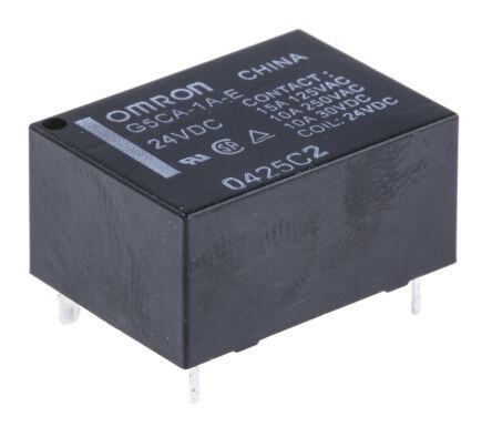
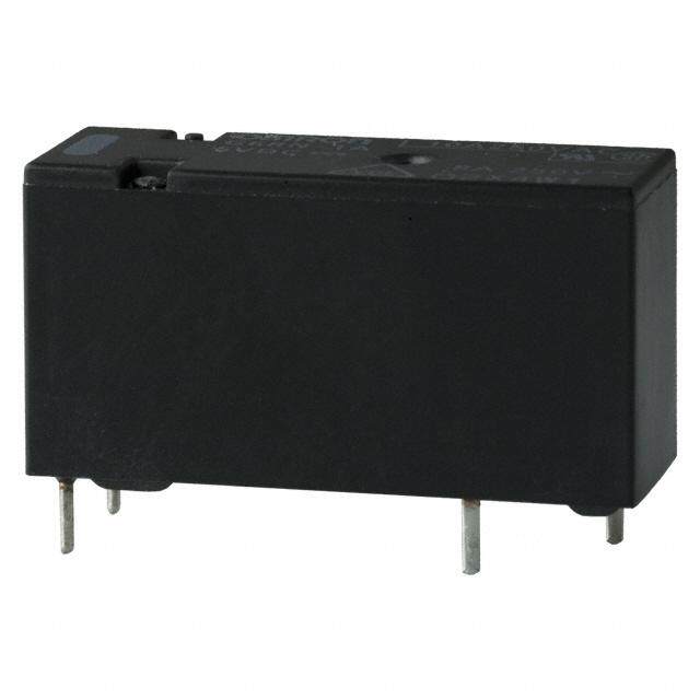
ICGOO电子元器件商城为您提供G5CA-1A-E DC24由Omron Electronics LLC设计生产,在icgoo商城现货销售,并且可以通过原厂、代理商等渠道进行代购。 G5CA-1A-E DC24价格参考¥24.16-¥41.42。Omron Electronics LLCG5CA-1A-E DC24封装/规格:功率继电器,高于 2 A, General Purpose Relay SPST-NO (1 Form A) 24VDC Coil Through Hole。您可以下载G5CA-1A-E DC24参考资料、Datasheet数据手册功能说明书,资料中有G5CA-1A-E DC24 详细功能的应用电路图电压和使用方法及教程。
型号为G5CA-1A-E DC24、品牌为Omron Electronics Inc-EMC Div的功率继电器,额定电流高于2A,广泛应用于工业自动化与电力控制领域。该继电器线圈电压为直流24V,控制信号兼容性强,适用于PLC控制系统、机械设备、电源设备及自动化产线中,用于实现小信号对大功率负载的通断控制。

典型应用场景包括:工业控制柜中的电机启停控制、加热设备的电源管理、空调与制冷系统的压缩机控制、自动门控制系统以及各类需要可靠开关动作的电气设备。其高绝缘性能和强抗干扰能力,确保在复杂电磁环境中稳定运行。此外,该继电器具备长寿命和高可靠性,适合频繁操作场合。

G5CA-1A-E DC24采用标准插座安装方式,便于维护与更换,是工业级应用中理想的中功率开关元件。
| 参数 | 数值 |
| 产品目录 | |
| 描述 | RELAY GEN PURPOSE SPST 15A 24V |
| 产品分类 | |
| 品牌 | Omron Electronics Inc-EMC Div |
| 数据手册 | |
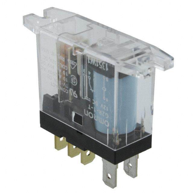
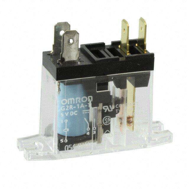
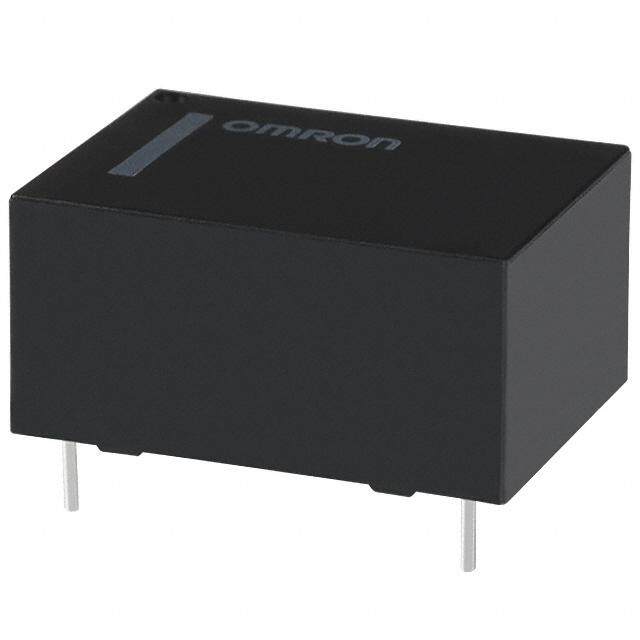
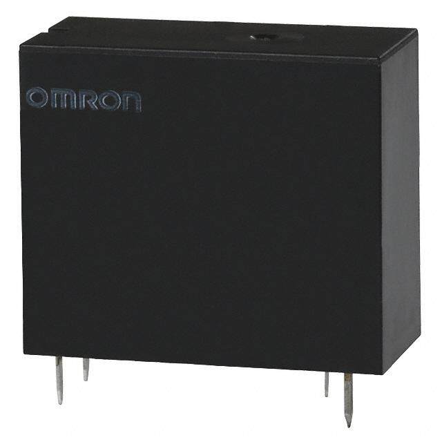
| 产品图片 |
|
| 产品型号 | G5CA-1A-E DC24 |
| rohs | 无铅 / 符合限制有害物质指令(RoHS)规范要求 |
| 产品系列 | G5CA |
| 产品培训模块 | http://www.digikey.cn/PTM/IndividualPTM.page?site=cn&lang=zhs&ptm=25458 |
| 产品目录绘图 |
|
| 产品目录页面 | |
| 关闭电压(最小值) | 2.4 VDC |
| 其它名称 | G5CA-1A-E-DC24 |
| 其它有关文件 | |
| 包装 | 散装 |
| 安装类型 | 通孔 |
| 导通电压(最大值) | 18 VDC |
| 工作时间 | 10ms |
| 工作温度 | -25°C ~ 70°C |
| 开关电压 | 250VAC,125VDC - 最小值 |
| 标准包装 | 20 |
| 特性 | 密封式 - 焊剂防护 |
| 端子类型 | PC 引脚 |
| 线圈功率 | 200 mW |
| 线圈电压 | 24VDC |
| 线圈电流 | 8.3mA |
| 线圈电阻 | 2.88 千欧 |
| 线圈类型 | 无锁存 |
| 继电器类型 | 通用 |
| 触头外形 | SPST-NO(1 A 型) |
| 触头材料 | - |
| 释放时间 | 10ms |
| 额定接触(电流) | 15A |

DC(5,12,24).jpg)


.jpg)


- 商务部:美国ITC正式对集成电路等产品启动337调查
- 曝三星4nm工艺存在良率问题 高通将骁龙8 Gen1或转产台积电
- 太阳诱电将投资9.5亿元在常州建新厂生产MLCC 预计2023年完工
- 英特尔发布欧洲新工厂建设计划 深化IDM 2.0 战略
- 台积电先进制程称霸业界 有大客户加持明年业绩稳了
- 达到5530亿美元!SIA预计今年全球半导体销售额将创下新高
- 英特尔拟将自动驾驶子公司Mobileye上市 估值或超500亿美元
- 三星加码芯片和SET,合并消费电子和移动部门,撤换高东真等 CEO
- 三星电子宣布重大人事变动 还合并消费电子和移动部门
- 海关总署:前11个月进口集成电路产品价值2.52万亿元 增长14.8%

.jpg)
PDF Datasheet 数据手册内容提取
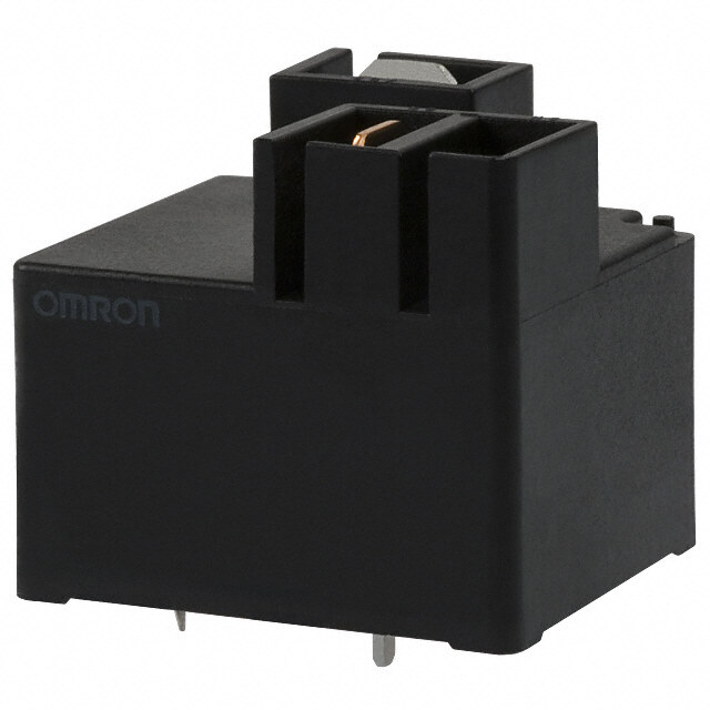
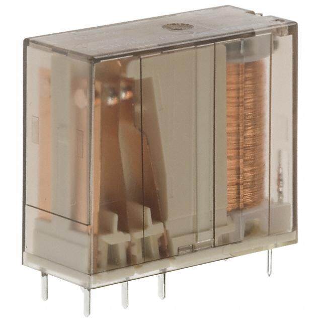
G5CA PCB Power Relay Flat Relays that Switch 10A/15A Loads Power •Ideal for switching power in household appliances or for outputs from industrial devices. •Subminiature dimensions: 16 × 22 × 11 mm (L × W × H). •High-sensitivity models available with low power consumption (150 mW). •Standard model conforms to UL/CSA standards. •Sealed models are available •Quick-connect terminal models are also available (#187 load contact terminals). •IEC/EN 60335-1 conformed. (-HA Model) RoHS Compliant ■Model Number Legend ■Application Examples G5CA-1A@-@-@-@-@ •Small home appliances ——— — — — — 1 2 3 4 5 6 1. Number of Poles 4. Classification G 1A: 1-pole/SPST-NO (1a) None:Standard 5 2. Enclosure rating E: High-capacity C None:Flux protection 5. Coil consumption A 4: Sealed None:Standard 3. Terminal Shape H: High-sensitivity None:PCB terminals 6. Market Code TP: Quick-connect None:General purpose terminals (#187) HA: Home Appliance according to IEC/EN60335-1 ■Ordering Information Terminal Shape Market Code Classification Contact form Enclosure rating Model Rated coil voltage Minimum packing unit Flux protection G5CA-1A Standard Sealed G5CA-1A4 5VDC General purpose Flux protection G5CA-1A-H 12VDC High-sensitivity PCB terminals Sealed G5CA-1A4-H 24VDC G5CA-1A-E SPST-NO (1a) 20 pcs/Tube 12VDC Home Appliance G5CA-1A-E-HA 24VDC High-capacity Flux protection 5VDC Quick-connect General purpose G5CA-1A-TP-E 12VDC terminals (#187) 24VDC Note 1.When ordering, add the rated coil voltage to the model number. Example: G5CA-1A DC5 Rated coil voltage However, the notation of the coil voltage on the product case as well as on the packing will be marked as @@ VDC. Note 2.Contact your OMRON representative for details on other coil voltage specifications. Note 3.High-capacity models with sealed structure are not available. Note 4.Standard or high-sensitivity models with quick-connect terminals are not available. ■Ratings ●Coil Item Must-operate voltage Must-release voltage Max. voltage Rated current Coil resistance Power consumption (mA) (Ω) (V) (V) (V) (mW) Classification Rated voltage % of rated voltage Standard, 5 VDC 40 125 150% (standard)/ high-capacity, 12 VDC 16.7 720 130% (high-capacity, 75% max. 10% min. Approx. 200 or quick-connect quick-connect terminals) 24 VDC 8.3 2,880 terminals (at 23°C) 5 VDC 30 167 150% High-sensitivity 12 VDC 12.5 960 80% max. 10% min. Approx. 150 (at 23°C) 24 VDC 6.25 3,840 Note 1.The rated current and coil resistance are measured at a coil temperature of 23°C with a tolerance of ±10%. Note 2.The operating characteristics are measured at a coil temperature of 23°C. Note 3.The “maximum voltage” is the maximum voltage that can be applied to the relay coil. 1
G5CA PCB Power Relay ●Contacts Classification Standard High-sensitivity High-capacity, or quick-connect terminals Inductive load Inductive load Inductive load Item Load Resistive load (cosφ = 0.4, L/R = 7 ms) Resistive load (cosφ = 0.4, L/R = 7 ms) Resistive load (cosφ = 0.4, L/R = 7 ms) Contact type Single Contact material Ag-alloy (Cd free) 10 A at 250 VAC; 3 A at 250 VAC; 10 A at 250 VAC; 3 A at 250 VAC; 15 A at 110 VAC; 5 A at 110 VAC; Rated load 10 A at 30 VDC 3 A at 30 VDC 10 A at 30 VDC 3 A at 30 VDC 10 A at 30 VDC 3 A at 30 VDC Rated carry current 10 A 10 A 15 A Max. switching voltage 250 VAC, 125 VDC Max. switching current 10 A 10 A 15 A ■Characteristics ■Engineering Data 30 mΩ max. ●Maximum Switching Capacity ●Durability CORInoepsnleuetrlaaaascttieeto rntteii mmrseieesBs tieastntwacneece *en1 c*2oil (11211Q50,0,50 u mm0m0ic00sssk VM-mmmcAΩoaaaCn xxxm,n... 5e(inH0c./ti6 gt0eh r-HmSzien fnoasrlsi t1 ivt ymitpyien m: 1o0d0e lms)Ω max.) Switching current (A) 53110050753 AGC5C reAs-i1sAtiv-Ee load AGC5A形C rCeAGs抵-5i1sAC抗tive負 lo荷adAG(cC5oC sinφA=d-0u1.cA4t-i)vEe load 4Durability (× 10 operation)531000753000000 250 VAC1 r1e0s iVsAtivCe rleosaidstive load and contacts DC resistive load Dielectric Between 1 GG55CCAA--11AA-E 10 strength contacts of 0.7 7 30 VDC resistive load the same 1,000 VAC, 50/60 Hz for 1 min 0.5 DC inductive load 5 polarity 0.3 GG55CCAA--11AA-E AGC5C inAd-u1cAtive load 3 Impulse withstand 4,500 V (1.2 x 50 μs) (L/R=7ms) (cosφ=0.4) voltage 0.1 1 1 3 5 7 10 30 50 100 300 500 1,000 0 2 4 6 8 10 12 14 16 G5 Vibration Destruction 1(10. 5to-m 5m5 tdoo 1u0b lHe za,m 0p.7li5tu-mdem) single amplitude Switching voltage (V) ●Operating TemperSawtituchirnge c uvrresnt. ( A) C resistance 10 to 55 to 10 Hz, 0.75-mm single amplitude ●Ambient Temperature vs. Must-operate/Must-release Malfunction A (1.5-mm double amplitude) Maximum Coil Voltage Voltage Shock Destruction 1,000 m/s2 rDeusriastbailnitcye MMaelcfuhnacntiicoanl 2oR2p00e(cid:129)(cid:129)e,0s0r i0mas2(hHtSe1t0t5iti/igir0agvo,s0mh00enh2n -0V, di ss0nlc0Aoa/e0aah arCno0lpdrsdsp a 1omietc0pirvio etaiAydtrty ia,eao t3mlnnio0dson0 dmsq,0e umi0lnsic0i.)nk ao.- ctpf oo1ern8r asn,0etei0oacn0lte s d m ainnd. Maximum coil voltage (%)211111110865432000000000 Cpeornmtiinsusoileu sv omltaaCpxgeo.ernm t(i1ins5us oiAleu) sv omltaaxg.e (10 A) Must-operate/must-release voltage (%)10864200000 SNaummpbleer: oGf 5RCeAla-y1sA: 5 pcs MMuusstt--roepleearasteemmmm vviiaaonnoxxll..tt..aXXaggee Electrical 110 VAC 15A, 100,000 operations min. 80 (cid:129) For all models 30 VDC 10 A, 100,000 operations 60 0 0 20 30 40 50 60 70 80 90 −40 −20 0 20 40 60 80 Inductive load Ambient temperature (°C) Ambient temperature (°C) 100,000 operations min. for all models Note.The "maximum voltage" is the (rated load) maximum voltage that can be applied [Switching frequency at 1,200 operations/h (for to the relay coil. all models)] ●Shock Malfunction Failure rate (P level) 5 VDC, 100 mA Y1,000 min. Unit: m/s2 (Reference value *3) 800 Ambient Operating temperature -25°C to 70°C (with no icing or condensation) 1,00X0 min. 600 1,00Z0 min. 400 Ambient Operating Sample: G5CA-1A humidity 5% to 85% 200 Number of Relays:10 pcs Weight Approx. 8 g (for TP model: Approx. 9.6 g) Measured value: The value at which 200 malfunction occurs in Note.Values in the above table are the initial values at 23(cid:129)C. 400 the contact when the **12.. MMeeaassuurreemmeenntt ccoonnddiittiioonnss:: M5 eVaDsCu,r e1d A a, tv tohleta sgaem der oppo imntest haosd t.he 1,00Z0' min. 600 1,00X0 'min. contact is subjected to dielectric strength using a 500 VDC ohmmeter. 800 Shock direction shock three times *3. This value was measured at a switching frequency of 120 operations/min. 1,000 min. Y X X' each in six directions Y' Z for three axes. Y' Z' Standard: 200 m/s2 2
G5CA PCB Power Relay ■Dimensions G5CA-1A(4) PCB Mounting Holes Terminal Arrangement/ (BOTTOM VIEW) Internal Connections G5CA-1A(4)-H Tolerance: ±0.1 mm (BOTTOM VIEW) G5CA-1A-E(-HA) 22 max. 16 max. 2.54 Two, 1 dia. hole (21.9)* (15.9)* 11 max. (10.9)* 2.54 1 2 12.7 3.5 1.6 0.4 0.4 0.4 4 3 10.16 7.62 12.7 (No coil polarity) * Average value Two, 1 dia. 2 elliptic holes 10.16 Note. Orientation marks are indicated 17.78 as follows: G5CA-1A-TP-E PCB Mounting Holes Terminal Arrangement/ (BOTTOM VIEW) Internal Connections 25.1 max. 22.1 max. Tolerance: ±0.1 mm (BOTTOM VIEW) (24.9)* 4.8 1.3 dia. 10°(2±11°.90).*5 Two, 1 dia. 1.8 Feloliuprt,ic 1 h.2o ldeisa. 4 1 6.35 11 3.2 13.4 3 (10.9)* 5 17.78 14.25 (TOP VIEW) 6.25 3.5 0.4 2 0.3 1.35 0.5 16.1 5 14.25 0.6 1.6 16.1 5 1 * Average value 17.78 21.1 (BOTTOM VIEW) G (No coil polarity) ■Approved Standards 5 C A ●The following UL-, CSA-, and EN/TÜV-certifying ratings differ from the performance characteristics of the individual models. UL Recognized: (File No. E41515) CSA Certified: (File No. LR31928) Number of Number of Contact Coil Contact Coil Model Contact ratings test Model Contact ratings test form ratings form ratings operations operations 15 A, 125 VAC (General purpose) 15 A, 125 VAC (General purpose) at 40°C at 40°C SPST-NO 5 to 24 SPST-NO 5 to 24 G5CA 10 A, 250 VAC (General purpose) 100,000 G5CA 10 A, 250 VAC (General purpose) 100,000 (1a) VDC (1a) VDC at 40°C at 40°C 10 A, 30 VDC (Resistive) at 40°C 10 A, 30 VDC (Resistive) at 40°C EN Certified/TÜV (Certificate No. R50214486) Number of Contact Coil Model Contact ratings test form ratings operations 15 A, 125 VAC (cosφ = 1.0) at 85°C G5CA SPST-NO 5, 12, 10 A, 250 VAC (cosφ = 1.0) at 100,000 (1a) 24 VDC 85°C 10 A, 30 VDC (0 ms) at 85°C Clearance distance 1.6 mm min. Creepage distance 3.2 mm min. Insulation material group IIIa Type of insulationcoil-contact circuit Basic open contact circuit Micro disconnection Rated Insulation voltage 250 V Pollution degree 2 Rated voltage system 250 V Over voltage category II Category of protection according to RT II (Flux protection) / IEC 61810-1 RT III (Sealed) <HA Models only> Glow wire according to GWT 750°C min. (IEC 60695-2-11) / IEC 60335-1 ed.5 GWFI 850°C min. (IEC 60695-2-12) Tracking resistance according to PTI 250 V min. (housing parts) IEC 60112 3
G5CA PCB Power Relay ■Precautions ●Please refer to “PCB Relays Common Precautions” for correct use. Correct Use ●Mounting ●Quick-connect Terminal ●Charged Terminals •Make sure that sufficient space is Connections •The section marked with dotted circles provided between relays when •Do not pass current through the PCB (indicated by arrows) in the following installing two or more relays side by of the load contact terminals diagram includes the charged side to facilitate heat dissipation. (quick-connect terminals). terminals of the relay. Insufficient heat dissipation may result •The terminals are compatible with When the relay is mounted on a PCB, in the relay malfunctioning. Faston receptacle #187 and are make sure that there are no metal suitable for positive-lock mounting. patterns on the section of the PCB Use only Faston terminals with the facing the portion of the relay shaded P2.i5tc4h :mm × 4 min. specified numbers. Select leads for in the following diagram. between terminals connecting Faston receptacles with wire diameters that are within the allowable range for the load current. Pitch: 2.54 mm × 3 min. 12.7 between terminals Do not apply excessive force to the terminals when mounting or dismounting the Faston receptacle. 8 6.5 0.18 Insert and remove terminals carefully G ●Other Precautions 5 one at a time. Do not insert terminals •The G5CA is a power relay designed C on an angle, or insert/remove multiple A for applications switching power loads terminals at the same time. such as heaters in electric household The following positive-lock connectors appliances. Do not use the G5CA to made by AMP are recommended. switch micro loads less than 100 mA, Contact the manufacturer directly for such as in signal applications. details on connectors including •Use fully sealed models if the relays availability. will require washing. Flux-protection Receptacle Type terminals * Positive housing models may malfunction or the relay's AMP 170330-1 AMP 172074-1 performance may be otherwise (170324-1) (natural color) adversely affected if cleaning fluid #187 AMP 170331-1 AMP 172074-4 terminals (170325-1) (yellow) enters the relay. (width: AMP 170332-1 AMP 172074-5 4.75 mm) (170326-1) (green) AMP 172074-6 (blue) * The numbers shown in parentheses are for air-feeding. (cid:129) Application examples provided in this document are for reference only. In actual applications, confirm equipment functions and safety before using the product. (cid:129) Consult your OMRON representative before using the product under conditions which are not described in the manual or applying the product to nuclear control systems, railroad systems, aviation systems, vehicles, combustion systems, medical equipment, amusement machines, safety equipment, and other systems or equipment that may have a serious influence on lives and property if used improperly. Make sure that the ratings and performance characteristics of the product provide a margin of safety for the system or equipment, and be sure to provide the system or equipment with double safety mechanisms. Note: Do not use this document to operate the Unit. OMRON Corporation Electronic and Mechanical Components Company Contact: www.omron.com/ecb Cat. No. J151-E1-07 0617(0207)(O) 4