ICGOO在线商城 > 继电器 > 功率继电器,高于 2 A > G2RL-1 DC12
 Datasheet下载
- 型号: G2RL-1 DC12
- 制造商: Omron Electronics LLC
- 库位|库存: xxxx|xxxx
- 要求:
| 数量阶梯 | 香港交货 | 国内含税 |
| +xxxx | $xxxx | ¥xxxx |
查看当月历史价格
查看今年历史价格
G2RL-1 DC12产品简介:
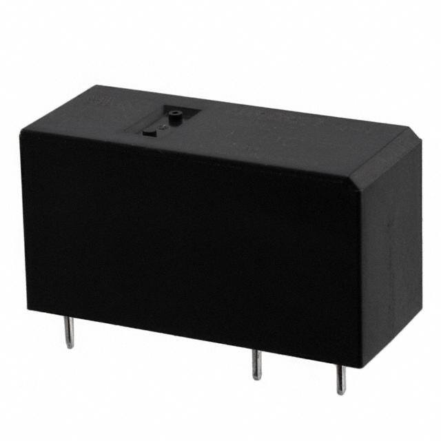
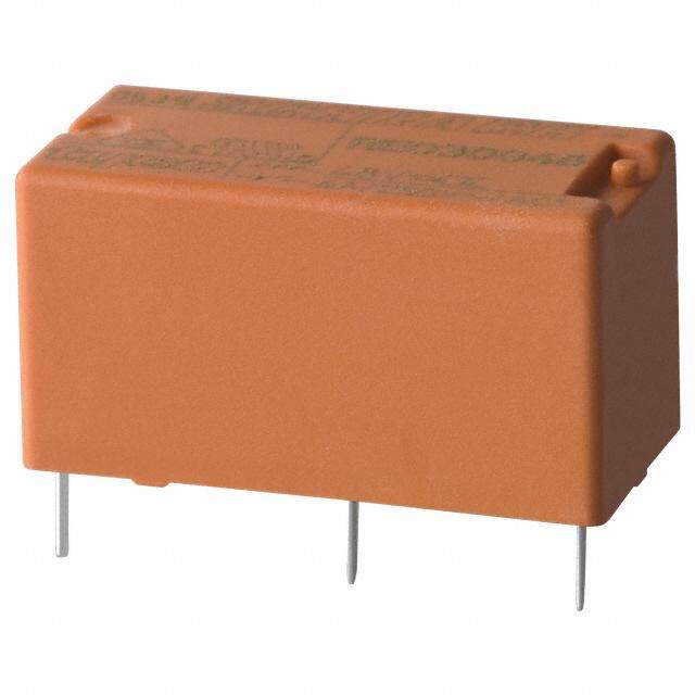
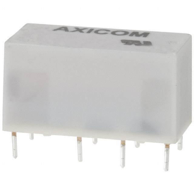
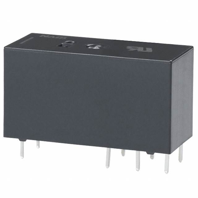
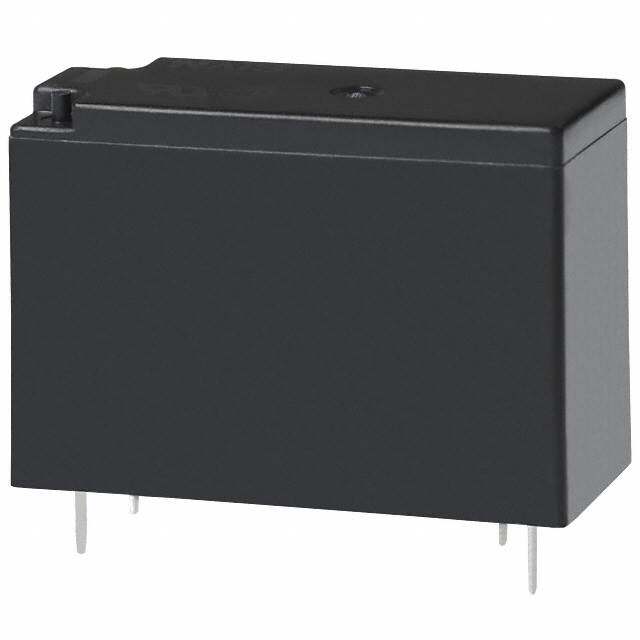
ICGOO电子元器件商城为您提供G2RL-1 DC12由Omron Electronics LLC设计生产,在icgoo商城现货销售,并且可以通过原厂、代理商等渠道进行代购。 G2RL-1 DC12价格参考¥12.84-¥22.81。Omron Electronics LLCG2RL-1 DC12封装/规格:功率继电器,高于 2 A, 通用 继电器 SPDT(1 Form C) 12VDC 线圈 通孔。您可以下载G2RL-1 DC12参考资料、Datasheet数据手册功能说明书,资料中有G2RL-1 DC12 详细功能的应用电路图电压和使用方法及教程。
Omron Electronics Inc-EMC Div生产的G2RL-1 DC12功率继电器是一款适用于多种工业和商业应用场景的高性能器件。该型号的额定电流为5 A(高于2 A),能够在12 V直流电压下可靠工作,具有高负载切换能力和长寿命特性。以下是其主要应用场景:

1. 工业自动化设备:
   G2RL-1 DC12可用于控制工业自动化系统中的电机、电磁阀或加热元件。例如,在生产线上的物料搬运设备中,该继电器可以用来控制驱动电机的启停或调节温度的加热装置。

2. 家用电器:
   在家用电器领域,这款继电器适合用于需要大电流切换的场景,如空调压缩机、洗衣机泵或电热器的控制电路。它能够确保设备在频繁开关时保持稳定运行。

3. 汽车电子系统:
   该继电器可应用于汽车电子设备中,例如车窗升降器、座椅加热器或灯光控制系统。由于其直流12V的工作电压与汽车电气系统匹配,因此非常适合车载环境。

4. 通信设备:
   在通信基站或其他电信设备中,G2RL-1 DC12可用于电源管理或信号切换模块,确保设备的高效运行并减少能耗。

5. 医疗设备:
   对于一些需要精确控制的医疗仪器,如超声波设备或诊断仪器,这款继电器可以提供可靠的负载切换功能,同时满足医疗行业的严格要求。

6. 照明控制:
   在智能照明系统中,该继电器可用于控制LED灯组或高强度放电灯(HID)的开关,适应室内外各种照明需求。

总之,G2RL-1 DC12功率继电器凭借其高电流承载能力、稳定的性能以及广泛的适用性,成为许多电力控制应用的理想选择。
| 参数 | 数值 |
| 产品目录 | |
| 描述 | RELAY GEN PURPOSE SPDT 12A 12V |
| 产品分类 | |
| 品牌 | Omron Electronics Inc-EMC Div |
| 数据手册 | |
| 产品图片 |
|
| 产品型号 | G2RL-1 DC12 |
| rohs | 无铅 / 符合限制有害物质指令(RoHS)规范要求 |
| 产品系列 | G2RL |
| 产品培训模块 | http://www.digikey.cn/PTM/IndividualPTM.page?site=cn&lang=zhs&ptm=25458 |
| 关闭电压(最小值) | 1.2 VDC |
| 其它名称 | G2RL-1-DC12 |
| 其它有关文件 | |
| 包装 | 散装 |
| 安装类型 | 通孔 |
| 导通电压(最大值) | 8.4 VDC |
| 工作时间 | 15ms |
| 工作温度 | -40°C ~ 85°C |
| 开关电压 | 440VAC,300VDC - 最小值 |
| 标准包装 | 200 |
| 特性 | 绝缘 - B 级,密封式 - 焊剂防护 |
| 端子类型 | PC 引脚 |
| 线圈功率 | 400 mW |
| 线圈电压 | 12VDC |
| 线圈电流 | 33.3mA |
| 线圈电阻 | 360 欧姆 |
| 线圈类型 | 无锁存 |
| 继电器类型 | 通用 |
| 触头外形 | SPDT(1 C 型) |
| 触头材料 | 银合金,无镉 |
| 释放时间 | 5ms |
| 额定接触(电流) | 12A |


- 商务部:美国ITC正式对集成电路等产品启动337调查
- 曝三星4nm工艺存在良率问题 高通将骁龙8 Gen1或转产台积电
- 太阳诱电将投资9.5亿元在常州建新厂生产MLCC 预计2023年完工
- 英特尔发布欧洲新工厂建设计划 深化IDM 2.0 战略
- 台积电先进制程称霸业界 有大客户加持明年业绩稳了
- 达到5530亿美元!SIA预计今年全球半导体销售额将创下新高
- 英特尔拟将自动驾驶子公司Mobileye上市 估值或超500亿美元
- 三星加码芯片和SET,合并消费电子和移动部门,撤换高东真等 CEO
- 三星电子宣布重大人事变动 还合并消费电子和移动部门
- 海关总署:前11个月进口集成电路产品价值2.52万亿元 增长14.8%

PDF Datasheet 数据手册内容提取
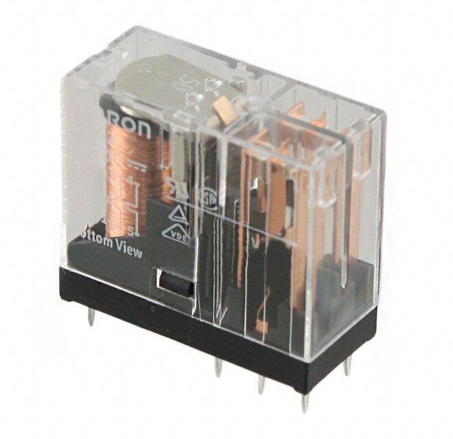
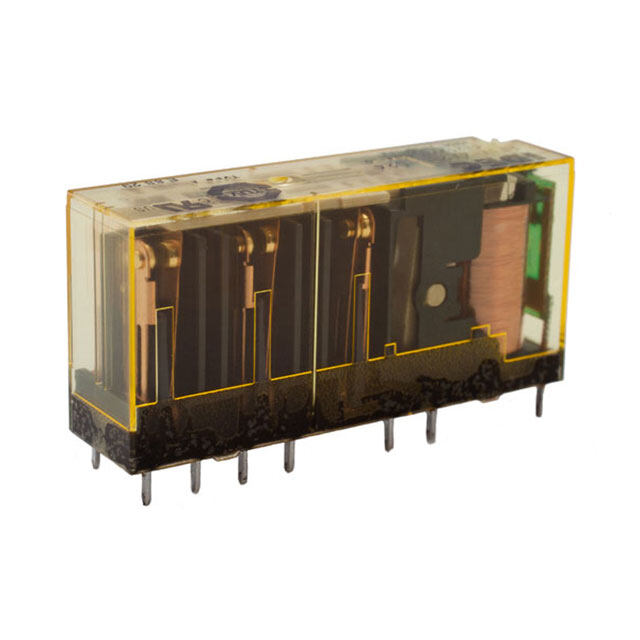
G2RL PCB Power Relay Low Profile Power Relay with 15.7 mm height, ideal for incorporation in miniature equipments •A wide variety of single pole, double pole, high-capacity (16 A) type and high-sensitivity type (250 mW) Relays are available. •Low profile; 15.7 mm max. in height. •Conforms to VDE (EN61810-1), UL508 and CSA22.2. •IEC/EN 60335-1 conformed. (-HA Model) •Satisfies ambient operating temperature requirement of 85°C and 105°C (-CV Model). •Clearance and creepage distance: 8 mm / 8 mm min. •Coil insulation system: Class F (UL1446). •G2RL-1A-E-ASI: TV3 Rating models available. RoHS Compliant ■Model Number Legend ■Application Examples G G2RL-@@@-@-@-@-@ •Home appliances 2 — — — — — — — R •OA equipments 1 2 3 4 5 6 7 L 1. Number of poles 5. Special Requirement •Industrial machinery 1 : 1 pole None: Standard 2 : 2 pole CV : 16 A, pinning 5 mm,: switching at 105°C 2. Contact Form 6. Market Code None: SPDT (1c) None: General purpose A : SPST-NO (1a) HA : Home Appliance according to IEC/EN60335-1 3. Enclosure rating 7. Contact material None: Flux protection None: Standard (Ag-alloy, Cd free) 4 : Sealed ASI : AgSnIn 4. Classification None: Standard E : High-capacity H : High-sensitivity ■Ordering Information Terminal Shape Market Code Classification Contact form Enclosure rating Model Rated coil voltage Minimum packing unit Flux protection G2RL-1A SPST-NO (1a) Sealed G2RL-1A4 Flux protection G2RL-1 SPDT (1c) Sealed G2RL-14 Standard Flux protection G2RL-2A DPST-NO (2a) 5 VDC Sealed G2RL-2A4 12 VDC Flux protection G2RL-2 DPDT (2c) 24 VDC General Sealed G2RL-24 48 VDC purpose G2RL-1A-E Flux protection SPST-NO (1a) G2RL-1A-E-ASI PCB terminals 20 pcs/tube Sealed G2RL-1A4-E High-capacity Flux protection G2RL-1-E SPDT (1c) Sealed G2RL-14-E G2RL-1A-E-CV SPST-NO (1a) G2RL-1A-H High-sensitivity SPDT (1c) G2RL-1-H 12 VDC DPST-NO (2a) Flux protection G2RL-2A-HA Standard 24 VDC Home DPDT (2c) G2RL-2-HA Appliance SPST-NO (1a) G2RL-1A-E-HA High-capacity SPDT (1c) G2RL-1-E-HA Note 1.When ordering, add the rated coil voltage to the model number. Example: G2RL-1A DC5 Rated coil voltage However, the notation of the coil voltage on the product case will be marked as @@VDC. Note 2.Place your order in tube (20 pcs/tube) units. Note 3.Contact your OMRON sales representative for sealed models. 1
G2RL PCB Power Relay ■Ratings ●Coil Item Must operate voltage Must release voltage Max. voltage Rated current Coil resistance Power consumption (V) (V) (V) (mA) (Ω) (mW) Rated voltage % of rated voltage 5 VDC 80.0 62.5 12 VDC 33.3 360 Approx. 400 Standard 70% max. 24 VDC 16.7 1,440 130% 10% min. 48 VDC 8.96 5,358 (at 85°C) Approx. 430 High- 12 VDC 20.8 576 75% max. Approx. 250 sensitivity 24 VDC 10.42 2,304 Note 1.The rated current and coil resistance are measured at a coil temperature of 23°C with a tolerance of ±10%. Note 2.The operating characteristics are measured at a coil temperature of 23°C. Note 3.The “Max. voltage” is the maximum voltage that can be applied to the relay coil. ●Contacts Classification Standard type (resistive load) High-capacity type (resistive load) High-sensitivity type (resistive load) Item Model G2RL-1A G2RL-1 G2RL-2A G2RL-2 G2RL-1A-E (-CV, -ASI) G2RL-1-E G2RL-1A-H G2RL-1-H Contact type Single Contact material Ag-alloy (Cd free) 12 A at 250 VAC 8 A at 250 VAC 16 A at 250 VAC Rated load 10 A at 250 VAC (See note) 12 A at 24 VDC (See note) 8 A at 30 VDC (See note) 16 A at 24 VDC (See note) 8 A (70°C)/5 A (85°C) Rated carry current 12 A (See note) 16 A (See note) 10 A (See note) (See note) Max. switching voltage 440 VAC, 300 VDC G 2 Max. switching current 12 A 8 A 16 A 10 A R Failure rate (P level) L (reference value*) 40 mA at 24 VDC * This value was measured at a switching frequency of 120 operations/min. Note:Contact your OMRON representative for the ratings on sealed models. ■Characteristics Classification Standard type High-capacity type High-sensitivity type Item Number of poles 1-pole 2-pole 1-pole Contact resistance *1 100 mΩ max. Operate (set) time 15 ms max. Release (reset) time 5 ms max. Insulation resistance *2 1,000 MΩ min. Between coil and 5,000 VAC, 50/60 Hz for 1min contacts Between contacts Dielectric of the same 1,000 VAC, 50/60 Hz for 1min strength polarity Between contacts − 2,500 VAC, 50/60 Hz for 1min − of different polarity Impulse withstand voltage 10 kV (1.2 x 50 μs) Vibration Destruction 10 to 55 to 10 Hz, 0.75 mm single amplitude (1.5 mm double amplitude) resistance Malfunction 10 to 55 to 10 Hz, 0.75 mm single amplitude (1.5 mm double amplitude) Shock Destruction 1,000 m/s2 resistance Malfunction Energized: 100 m/s2, De-energized: 100 m/s2 Mechanical 20,000,000 operations (at 18,000 operations/hr) G2RL-1(A)-E, G2RL-1A-E-ASI: 30,000 operations at 250 VAC, 16 A G2RL-1(A): G2RL-2(A): Durability Electrical *3 30,000 operations at 24 VDC, 16 A G2RL-1(A)-H: 50,000 operations at 250 VAC, 12 A 30,000 operations at 250 VAC, 8 A (resistive load) G2RL-1A-E-CV: 50,000 operations at 250 VAC, 10 A 30,000 operations at 24 VDC, 12 A 30,000 operations at 30 VDC, 8 A 50,000 operations at 250 VAC, 16 A at 105°C -40°C to 85°C (with no icing or condensation) Ambient operating temperature -40°C to 105°C (with no icing or condensation) by G2RL-1A-E-CV Ambient operating humidity 5% to 85% (with no icing or condensation) Weight Approx. 12 g Note.Values in the above table are the initial values at 23°C. *1. Measurement conditions: 5 VDC, 1 A, voltage drop method *2. Measurement conditions: Measured at the same points as the dielectric strength using a 500 VDC ohmmeter. *3. 1,800 operations per hour. 2
G2RL PCB Power Relay ■Engineering Data ●Maximum Switching Capacity G2RL-1A, G2RL-1 G2RL-1A-E, G2RL-1-E G2RL-2A, G2RL-2 A) 50 A) 50 A) 50 witching current ( 10 AC resistive load witching current ( 10 AC resistive load witching current ( 10 AC resistive load S 5 S 5 S 5 DloCad resistive DloCad resistive DloCad resistive 1 1 1 0.5 0.5 0.5 0.1 0.1 0.1 0 5 10 20 30 50 100 500 1,000 0 5 10 20 30 50 100 500 1,000 0 5 10 20 30 50 100 500 1,000 Switching voltage (V) Switching voltage (V) Switching voltage (V) ●High-sensitivity type ●Ambient Temperature vs. Rated ●Ambient Temperature vs. Maximum G2RL-1A-H, G2RL-1-H Carry Current Coil Voltage Switching current (A) 51005 DC reAsCis trivees i stive load Rated Carry Current (A) 21110652 GGG222RRRLLL---111AAA-,- EHG,, 2GGR22LRR-1LL--11--EH Maximum coil voltage (%) 122185050000 G2RL-1A-E-CV GR2L load 10 130 110 8 100 1 G2RL-2A, G2RL-2 Other type 0.5 5 50 0.1 0 5 10 20 30 50 100 500 1,000 0 10 20 30 40 50 60 70 80 8590 100 0 10 20 30 40 50 60 70 80 85 90 100 105 110 Switching voltage (V) Ambient temperature (°C) Ambient temperature (°C) Note.The maximum coil voltage refers to the maximum value in a varying range of operating power voltage, not a continuous voltage. ●Ambient Temperature vs. Must Operate and Must Release Voltages Must operate/must release voltage(percentage of rated voltage) (%)109876540000000 SGNau2mmRpLbl-ee1r:4 o-Ef r e2l4a yVsD: 5C pcs MMuusstt orepleearastee vvoollttmmaaXggaineex.. 30 max. X min. 20 10 0 20 40 60 80 100 120 Ambient temperature (°C) 3
G2RL PCB Power Relay ●Shock Malfunction G2RL-1 (A)-E G2RL-2 (A) Y Y 1,000 1,000 NO contact NO contact Sample: G2RL-14 12 VDC Sample: G2RL-24 12 VDC Number of Relays: 5 pcs Number of Relays: 5 pcs X' Z Test conditions: Shock is applied X' Z Test conditions: Shock is applied 1,000 1,000 1,000 1,000 in ±X, ±Y, and ±Z directions three in ±X, ±Y, and ±Z directions three times each with without energizing times each with without energizing 130 the Relays to check the number of 150 the Relays to check the number of malfunctions. malfunctions. Requirement: None malfuction Requirement: None malfuction 1,00Z0' NC contact 1X,000 100 m/s2 1,00Z0' NC contact 1X,000 100 m/s2 Shock direction Shock direction X X' X X' Y Y 1,000 Unit: m/s2 Z 1,000 Unit: m/s2 Z Y' Z' Y' Z' Y' Y' ■Electrical Endurance Data (Reference Value) 8 A 250 VAC (cosφ=0.4) 200,000 operation min. (N.O.) G2RL-1-E 8 A 30 VDC (L/R=7 ms) 10,000 operation min. (N.O.) 5 A 250 VAC (cosφ=0.4) 150,000 operation min. (N.O.) G2RL-1 5 A 30 VDC (L/R=7 ms) 10,000 operation min. (N.O.) G G2RL-2 8 A 250 VAC (cosφ=1) 30,000 operation min. 2 8 A 30 VDC 10,000 operation min. R Pilot duty (A300), 250 VAC250,000 operation min. G2RL-1A-E L Pilot duty (A300), 125 VAC150,000 operation min. Note.The results shown reflect values at ambient temperature 23°C. Electrical endurance will vary depending on the test conditions. Contact your OMRON representative if you require more detailed information for the electrical endurance under your test condition. ■Dimensions (Unit: mm) G2RL-1A, G2RL-1A4, G2RL-1A-H PCB Mounting Holes Terminal Arrangement/ (Bottom View) InternalConnections 3.5 (BottomView) 12.7 max. Four, 1.3-dia. holes 29 max. (12.5)* (28.8)* (2.5) 1 3 7.5 15.7 max. (15.5)* 5 4 (2.3) 20 (No coil polarity) 3.5 0.5 0.5 0.8 0.5 * Average value G2RL-1, G2RL-14, G2RL-1-H PCB Mounting Holes Terminal Arrangement/ (Bottom View) InternalConnections 3.53.5 Five, 1.3-dia. holes (BottomView) 12.7 max. 29 max. (12.5)* (2.5) 1 2 3 (28.8)* 7.5 15.7 max. (15.5)* 5 4 (2.3) 20 (No coil polarity) 3.5 0.5 0.5 0.8 0.5 0.5 * Average value G2RL-1A-E (-HA), G2RL-1A4-E, G2RL-1A-E-CV, G2RL-1A-E-ASI PCB Mounting Holes Terminal Arrangement/ (Bottom View) InternalConnections 5 (BottomView) 12.7 max. Six, 1.3-dia. holes 29 max. (12.5)* (28.8)* (2.5) 1 3 4 7.5 15.7 max. (15.5)* 8 6 5 (2.3) 20 (No coil polarity) 3.5 0.5 0.5 0.8 0.5 * Average value 4
G2RL PCB Power Relay G2RL-1-E (-HA), G2RL-14-E PCB Mounting Holes Terminal Arrangement/ (Bottom View) InternalConnections 12.7 max. 5 5 Eight, 1.3-dia. holes(BottomView) 29 max. (12.5)* (28.8)* (2.5) 1 2 3 4 7.5 15.7 max. (15.5)* 8 7 6 5 (2.3) 20 (No coil polarity) 3.5 0.5 0.5 0.8 0.5 0.5 * Average value G2RL-2A (-HA), G2R-2A4 PCB Mounting Holes Terminal Arrangement/ (Bottom View) InternalConnections 5 (BottomView) 12.7 max. Six, 1.3-dia. holes 29 max. (12.5)* (28.8)* (2.5) 1 3 4 7.5 15.7 max. (15.5)* 8 6 5 (2.3) 20 (No coil polarity) 3.5 0.5 0.5 0.8 0.5 * Average value G2RL-2 (-HA), G2R-24 PCB Mounting Holes Terminal Arrangement/ G (Bottom View) InternalConnections 2 12.7 max. 5 5 Eight, 1.3-dia. holes(BottomView) RL 29 max. (12.5)* (28.8)* (2.5) 1 2 3 4 7.5 15.7 max. (15.5)* 8 7 6 5 (2.3) 20 (No coil polarity) 3.5 0.5 0.5 0.8 0.5 0.5 * Average value ■Approved Standards • The approval rating values for overseas standards are different from the performance values determined individually. Confirm the values before use. UL Recognized: (File No. 41643) CSA Certified: (File No. LR31928) Number of test Model Contact form Coil ratings Contact ratings operations G2RL-1A SPST-NO (1a) 12 A, 250 VAC (General Use) 40°C 100,000 3 to 48 VDC G2RL-1 SPDT (1c) 12 A, 24 VDC (Resistive) 40°C 50,000 G2RL-1A-E (-HA) SPST-NO (1a) 16 A, 250 VAC (General Use) 40°C 100,000 3 to 48 VDC G2RL-1-E (-HA) SPDT (1c) 16 A, 24 VDC (Resistive) 40°C 50,000 16 A, 250 VAC (Resistive) 85°C 30,000 G2RL-1A-E-ASI SPST-NO (1a) 3 to 48 VDC TV-3 40°C 25,000 G2RL-1A-E-CV SPST-NO (1a) 3 to 48 VDC 16 A, 250 VAC (Resistive) 105°C 100,000 G2RL-1A-H SPST-NO (1a) 10 A, 250 VAC (General Use) 40°C 3 to 48 VDC 50,000 G2RL-1-H SPDT (1c) 10 A, 24 VDC (Resistive) 40°C G2RL-2A (-HA) DPST-NO (2a) 8 A, 277 VAC (General Use) 40°C 3 to 48 VDC 100,000 G2RL-2 (-HA) DPDT (2c) 8 A, 30 VDC (Resistive) 40°C 5
G2RL PCB Power Relay EN/IEC, VDE Certified (Certificate No. 119650) Number of test Model Contact form Coil ratings Contact ratings operations 12 A, 250 VAC (cosφ=1) 85°C G2RL-1A SPST-NO (1a) 100,000 12 A, 24 VDC (L/R=0 ms) 85°C 3 to 48 VDC AC15:3 A at 240 VAC at room temperature G2RL-1 SPDT (1c) 6,000 DC13:2.5 A at 24 VDC, 50ms at room temperature 16 A, 250 VAC (cosφ=1) 85°C 30,000 G2RL-1A-E (-HA) SPST-NO (1a) 16 A, 24 VDC (L/R=0 ms) 85°C 15,000 3 to 48 VDC AC15:3 A at 240 VAC (NO) at room temperature, G2RL-1-E (-HA) SPDT (1c) 1.5 A at 240V AC (NC) at room temperature 6,000 DC13:2.5 A at 24 VDC (NO), 50ms at room temperature G2RL-1A-E-ASI SPST-NO (1a) 3 to 48 VDC 16 A, 250 VAC (cosφ=1) 85°C 30,000 G2RL-1A-E-CV SPST-NO (1a) 3 to 48 VDC 16 A, 250 VAC (cosφ=1) 105°C 100,000 10 A, 250 VAC (cosφ=1) 85°C 50,000 G2RL-1A-H SPST-NO (1a) 3 to 48 VDC 10 A, 250 VAC (cosφ=1) 40°C 100,000 G2RL-1-H SPDT (1c) 10 A, 24 VDC (L/R=0 ms) 85°C 50,000 8 A, 250 VAC (cosφ=1) 85°C 30,000 G2RL-2A (-HA) DPST-NO (2a) 8 A, 30 VDC (L/R=0 ms) 85°C 15,000 3 to 48 VDC AC15:1.5 A at 240VAC at room temperature G2RL-2 (-HA) DPDT (2c) 6,000 DC13:2 A at 30 VDC, 50ms at room temperature Creepage distance 8 mm min. Clearance distance 8 mm min. Insulation material group IIIa Type of insulation coil-contact circuit Reinforced G open contact circuit Micro disconnection 2 Rated Insulation voltage 250 V R L Pollution degree 3 (Flux protection / Sealed) Rated voltage system 250 V / 400 V (Flux protection) Over voltage category III Category of protection according to IEC 61810-1 RT II (Flux protection) / RT III (Sealed) <HA Models only> Glow wire according to IEC 60335-1 GWT 750°C min. (IEC 60695-2-11) / GWFI 850°C min. (IEC 60695-2-12) Tracking Index of relay base PTI 250 V min. (housing parts) ■Precautions • Please refer to “PCB Relays Common Precautions” for correct use. ●Cleaning Correct Use •The G2RL model is flux-resistant with two sealing holes on the ●Mounting Position Compared to G2R Model case. Thus, do not clean the Relay by boiling or soaking in water. Consult your Omron sales representative for sealed •Although the G2RL model and the G2R model are both low type Relay. profile Relays, their characteristics such as switching capacity are different. Be sure to check operation under the actual ●Using Relays in an Atmosphere Containing Corrosive operating conditions before use. Gas •Do not use Relays in an atmosphere containing corrosive gas (sulfuric or organic gas).Otherwise, connection failure due to corrosion on the contact surface may lead to functional faults. (cid:129) Application examples provided in this document are for reference only. In actual applications, confirm equipment functions and safety before using the product. (cid:129) Consult your OMRON representative before using the product under conditions which are not described in the manual or applying the product to nuclear control systems, railroad systems, aviation systems, vehicles, combustion systems, medical equipment, amusement machines, safety equipment, and other systems or equipment that may have a serious influence on lives and property if used improperly. Make sure that the ratings and performance characteristics of the product provide a margin of safety for the system or equipment, and be sure to provide the system or equipment with double safety mechanisms. Note: Do not use this document to operate the Unit. OMRON Corporation Electronic and Mechanical Components Company Contact: www.omron.com/ecb Cat. No. J117-E1-11 1116(0207)(O) 6