ICGOO在线商城 > 继电器 > 功率继电器,高于 2 A > G2R-1-E-DC12
 Datasheet下载
- 型号: G2R-1-E-DC12
- 制造商: Omron Electronics LLC
- 库位|库存: xxxx|xxxx
- 要求:
| 数量阶梯 | 香港交货 | 国内含税 |
| +xxxx | $xxxx | ¥xxxx |
查看当月历史价格
查看今年历史价格
G2R-1-E-DC12产品简介:
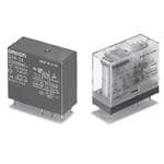
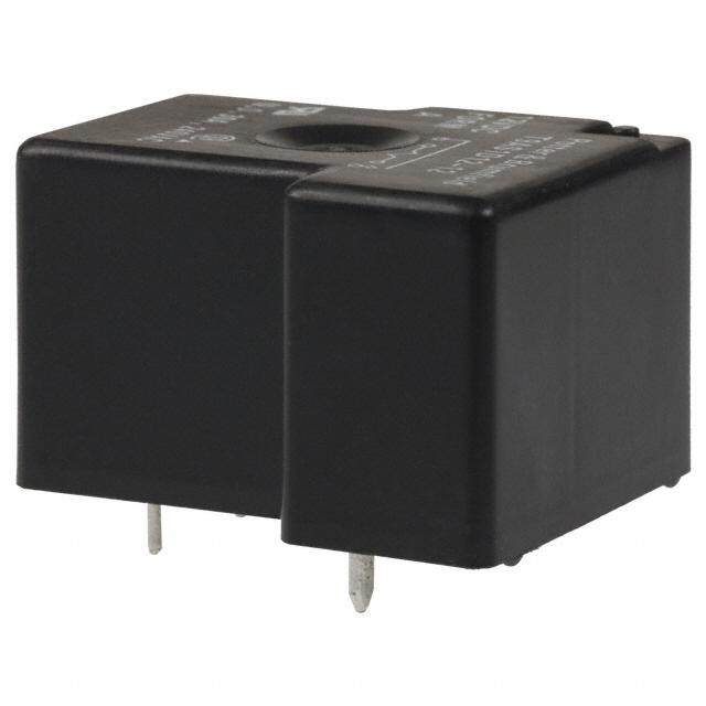
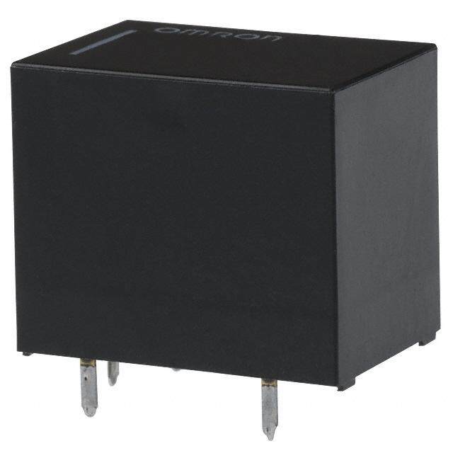
ICGOO电子元器件商城为您提供G2R-1-E-DC12由Omron Electronics LLC设计生产,在icgoo商城现货销售,并且可以通过原厂、代理商等渠道进行代购。 G2R-1-E-DC12价格参考¥13.41-¥15.40。Omron Electronics LLCG2R-1-E-DC12封装/规格:功率继电器,高于 2 A, 通用 继电器 SPDT(1 Form C) 12VDC 线圈 通孔。您可以下载G2R-1-E-DC12参考资料、Datasheet数据手册功能说明书,资料中有G2R-1-E-DC12 详细功能的应用电路图电压和使用方法及教程。
Omron Electronics Inc-EMC Div生产的G2R-1-E-DC12功率继电器,是一款适用于多种工业和商业应用场景的高品质继电器。该型号的继电器额定电流为5A(在250VAC条件下),远高于2A的要求,因此非常适合用于需要较高电流承载能力的设备和系统中。

 应用场景:

1. 工业自动化控制:
   G2R-1-E-DC12继电器广泛应用于工厂自动化控制系统中,如PLC(可编程逻辑控制器)输出模块、电机启动器、变频器等。它可以可靠地控制大功率负载,确保生产线的稳定运行。

2. 电力配电系统:
   在电力配电系统中,这款继电器可用于低压断路器、接触器等设备的控制电路中,实现对电路的通断控制。其高电流承载能力和稳定的性能,确保了电力系统的安全性和可靠性。

3. 照明控制系统:
   对于大型建筑或公共场所的照明控制系统,G2R-1-E-DC12可以用来控制高压钠灯、LED灯等大功率照明设备的开关,保证照明系统的高效运行。

4. 家电产品:
   在一些高端家用电器中,如空调、冰箱、洗衣机等,G2R-1-E-DC12继电器可以用于控制压缩机、风扇等关键部件的电源通断,确保家电的安全和稳定工作。

5. 电动汽车充电站:
   随着电动汽车的普及,充电站的建设也越来越多。G2R-1-E-DC12继电器可以用于充电站的充电控制电路中,确保充电过程的安全性和稳定性。

6. 通信基站:
   在通信基站中,G2R-1-E-DC12继电器可用于电源管理模块,控制基站设备的电源通断,确保通信设备的正常运行。

7. 医疗设备:
   在一些需要高可靠性的医疗设备中,如X光机、CT扫描仪等,G2R-1-E-DC12继电器可以用于控制高压发生器等关键部件的电源,确保设备的安全性和精度。

总之,Omron G2R-1-E-DC12功率继电器凭借其高电流承载能力、可靠的性能和长寿命,适用于各种需要大电流控制的应用场景,特别是在工业自动化、电力系统、照明控制等领域表现尤为突出。
| 参数 | 数值 |
| 产品目录 | |
| 描述 | RELAY GEN PURPOSE SPDT 16A 12V通用继电器 High-Capacity SPDT Vented 12VDC |
| 产品分类 | |
| 品牌 | Omron Electronics |
| 产品手册 | |
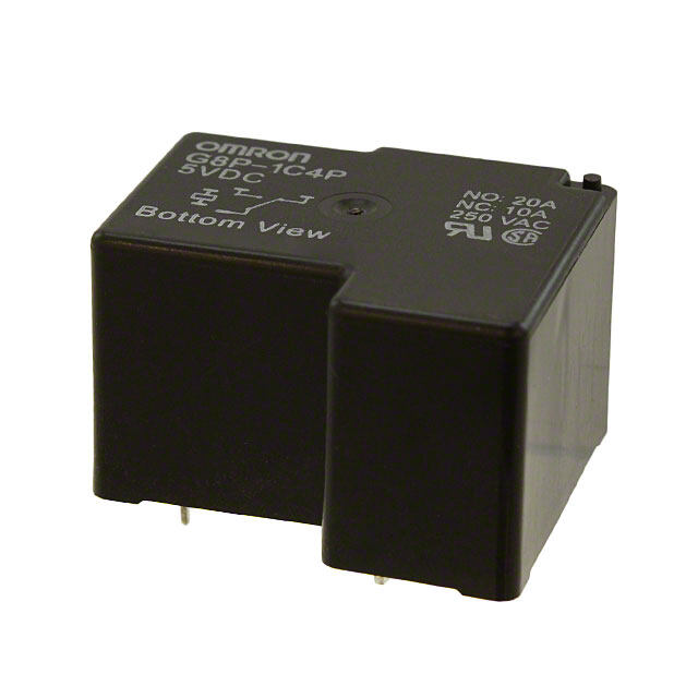
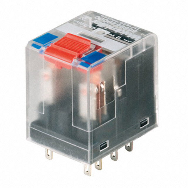
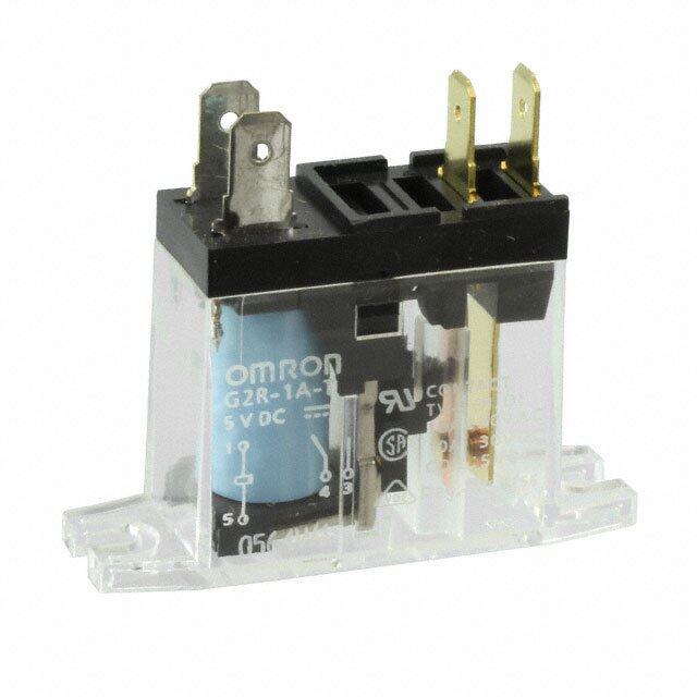
| 产品图片 |
|
| rohs | 符合RoHS无铅 / 符合限制有害物质指令(RoHS)规范要求 |
| 产品系列 | 通用继电器,Omron Electronics G2R-1-E-DC12G2R |
| mouser_ship_limit | 该产品可能需要其他文件才能进口到中国。 |
| 数据手册 | |
| 产品型号 | G2R-1-E-DC12 |
| 产品培训模块 | http://www.digikey.cn/PTM/IndividualPTM.page?site=cn&lang=zhs&ptm=25458 |
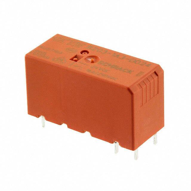
| 产品目录绘图 |
|
| 产品目录页面 | |
| 产品种类 | 通用继电器 |
| 关闭电压(最小值) | 1.8 VDC |
| 其它名称 | G2R1E12DC |
| 其它有关文件 | |
| 功耗 | 0.53 W |
| 包装 | 散装 |
| 商标 | Omron Electronics |
| 安装类型 | 通孔 |
| 安装风格 | Through Hole |
| 宽度 | 13 mm |
| 导通电压(最大值) | 8.4 VDC |
| 工作时间 | 15ms |
| 工作温度 | -40°C ~ 70°C |
| 工厂包装数量 | 100 |
| 开关电压 | 380VAC,125VDC - 最小值 |
| 标准包装 | 100 |
| 特性 | 密封式 - 焊剂防护 |
| 端子类型 | PC 引脚 |
| 系列 | G2R |
| 线圈功率 | 530 mW |
| 线圈电压 | 12 V |
| 线圈电流 | 43.6 mA |
| 线圈电阻 | 275 Ohms |
| 线圈类型 | 无锁存 |
| 继电器类型 | 通用 |
| 触头外形 | SPDT(1 C 型) |
| 触头材料 | 银合金 |
| 触点形式 | SPDT (1 Form C) |
| 触点材料 | Silver Cadmium Oxide |
| 触点电流额定值 | 16 A |
| 释放时间 | 5ms |
| 长度 | 29 mm |
| 零件号别名 | 373159 G2R1E12DC G2R1EDC12BYOMI G2R1EDC12NC G2RN8102M |
| 额定接触(电流) | 16A |
| 高度 | 25.3 mm |


- 商务部:美国ITC正式对集成电路等产品启动337调查
- 曝三星4nm工艺存在良率问题 高通将骁龙8 Gen1或转产台积电
- 太阳诱电将投资9.5亿元在常州建新厂生产MLCC 预计2023年完工
- 英特尔发布欧洲新工厂建设计划 深化IDM 2.0 战略
- 台积电先进制程称霸业界 有大客户加持明年业绩稳了
- 达到5530亿美元!SIA预计今年全球半导体销售额将创下新高
- 英特尔拟将自动驾驶子公司Mobileye上市 估值或超500亿美元
- 三星加码芯片和SET,合并消费电子和移动部门,撤换高东真等 CEO
- 三星电子宣布重大人事变动 还合并消费电子和移动部门
- 海关总署:前11个月进口集成电路产品价值2.52万亿元 增长14.8%

PDF Datasheet 数据手册内容提取
G2R PCB Power Relay The Best Seller G2R •1General purpose power Relays of single-pole10 A and double-pole 5 A. •Safety-oriented design with dielectric strength of 5,000 V between coil and contacts, and surge resistance of 10,000 V. •AC and DC types are both available for operational coils. RoHS Compliant ■Model Number Legend G2R-@-@@@@-@@ — — — — — — — 1 2 3 4 5 6 7 1. Relay Function 4. Contact Type 6. Terminal Shape 7. Classification G None: Single-side stable None: Single None: PCB terminals None: Standard 2 K : Double-winding latching Z : Bifurcated contact T : Quick-connect E : High-capacity R (upper bracket H : High-sensitivity 2. Number of poles 5. Enclosure rating mounting #187) U : For ultrasonically 1: 1-pole None: Flux protection cleanable 2: 2-pole (T-type is an enclosed Z : Full-wave rectifier relay) 3. Contact Form 4 : Fully sealed None: NO/NC A : NO ■Model Configuration Number of poles 1-pole 2-pole Minimum Terminal Classification Enclosure Contact packing Shape rating form SPST-NO (1a) SPDT (1c) DPST-NO (2a) DPDT (2c) unit AC Flux protection G2R-1A G2R-1 G2R-2A G2R-2 DC 100 Standard AC pcs/tray Fully sealed G2R-1A4 G2R-14 G2R-2A4 G2R-24 DC Bifurcated Flux protection G2R-1AZ G2R-1Z − − 50 DC PCB terminals contact Fully sealed G2R-1AZ4 G2R-1Z4 − − pcs/tray AC High-capacity Flux protection G2R-1A-E G2R-1-E − − 100 DC pcs/tray High-sensitivity Flux protection DC G2R-1A-H G2R-1-H G2R-2A-H G2R-2-H Double-winding 50 Flux protection DC G2RK-1A G2RK-1 G2RK-2A G2RK-2 latching pcs/tray Quick-connect Standard Unsealed AC G2R-1A-T G2R-1-T − − 100 DC pcs/tray Note 1.Full-wave rectifier and supersonic cleaner compatible models are also available. Refer to page 3. 2.Sockets for PCB terminal models are not provided. 1
G2R PCB Power Relay ■Ordering Information ●PCB Terminal Models Number of poles 1-pole 2-pole Classification Enclosure rating Contact form Model Rated coil voltage Model Rated coil voltage 12, 24, 100/(110) VAC 12, 24, 100/(110) VAC 200/(220) VAC 200/(220) VAC NO G2R-1A G2R-2A 5, 6, 12, 24, 48 VDC 5, 6, 12, 24, 48 VDC 100 VDC 100 VDC Flux protection 12, 24, 100/(110) VAC 12, 24, 100/(110) VAC 200/(220) VAC 200/(220) VAC NO/NC G2R-1 G2R-2 5, 6, 12, 24, 48 VDC 5, 6, 12, 24, 48 VDC 100 VDC 100 VDC Standard 12, 24, 100/(110) VAC 12, 24, 100/(110) VAC 200/(220) VAC 200/(220) VAC NO G2R-1A4 G2R-2A4 5, 6, 12, 24, 48 VDC 5, 6, 12, 24, 48 VDC 100 VDC 100 VDC Fully sealed 12, 24, 100/(110) VAC 12, 24, 100/(110) VAC 200/(220) VAC 200/(220) VAC NO/NC G2R-14 G2R-24 5, 6, 12, 24, 48 VDC 5, 6, 12, 24, 48 VDC 100 VDC 100 VDC NO G2R-1A-H 5, 6, 12, 24, 48 VDC G2R-2A-H 5, 6, 12, 24, 48 VDC G High-sensitivity 2 NO/NC G2R-1-H 5, 6, 12, 24, 48 VDC G2R-2-H 5, 6, 12, 24, 48 VDC Flux protection R Double-winding NO G2RK-1A 5, 6, 12, 24 VDC G2RK-2A 5, 12, 24 VDC latching NO/NC G2RK-1 5, 6, 12, 24 VDC G2RK-2 5, 6, 12, 24 VDC 12, 24, 48 VDC NO G2R-1AZ 100 VDC Flux protection − 5, 6, 12, 24, 48 VDC NO/NC G2R-1Z Bifurcated 100 VDC contact 5, 12, 24, 48 VDC NO G2R-1AZ4 100 VDC Fully sealed − 5, 12, 24, 48 VDC NO/NC G2R-1Z4 100 VDC 12, 24, 100/(110) VAC 200/(220) VAC NO G2R-1A-E − 5, 6, 12, 24, 48 VDC 100 VDC High-capacity Flux protection 12, 24, 100/(110) VAC 200/(220) VAC NO/NC G2R-1-E − 5, 6, 12, 24, 48 VDC 100 VDC Note:When ordering, add the rated coil voltage to the model number. Example: G2R-1A AC12 Rated coil voltage However, the notation of the coil voltage on the product case as well as on the packing will be marked as @@ VAC. 2
G2R PCB Power Relay ●Quick-connect Terminal (#187) Number of poles 1-pole Classification Enclosure rating Contact form Model Rated coil voltage 12, 24, 100/(110) VAC 200/(220) VAC NO G2R-1A-T 5, 6, 12, 24, 48 VDC 100 VDC Standard Unsealed 12, 24, 100/(110) VAC 200/(220) VAC NO/NC G2R-1-T 5, 6, 12, 24, 48 VDC 100 VDC ●Full-wave Rectifier Number of poles 1-pole 2-pole Classification Enclosure rating Contact form Model Rated coil voltage Model Rated coil voltage 5, 12, 24 VDC 5, 6, 12, 24, 48 VDC NO G2R-1A-Z G2R-2A-Z 100 VDC 100 VDC Flux protection 5, 12, 24, 48 VDC 12, 24, 48 VDC NO/NC G2R-1-Z G2R-2-Z 100 VDC 100 VDC Standard 5, 12, 48 VDC 24, 48 VDC NO G2R-1A4-Z G2R-2A4-Z 100 VDC 100 VDC Fully sealed 5, 12, 24, 48 VDC 5, 12, 24 VDC G NO/NC G2R-14-Z G2R-24-Z 100 VDC 100 VDC 2 R 5, 12, 24 VDC NO G2R-1A-EZ High-capacity Flux protection 100 VDC − NO/NC G2R-1-EZ 12, 24, 48 VDC ●For Ultrasonically Cleanable Number of poles 1-pole 2-pole Classification Enclosure rating Contact form Model Rated coil voltage Model Rated coil voltage 12, 24, 100/(110) VAC 100/(110) VAC NO G2R-1A4-U 200/(220) VAC G2R-2A4-U − 5, 6, 12, 24, 48 VDC 5, 12, 24 VDC Standard Fully sealed 100/(110) VAC 24, 100/(110) VAC 200/(220) VAC 200/(220) VAC NO/NC G2R-14-U G2R-24-U 5, 12, 24, 48 VDC 5, 12, 24, 48 VDC 100 VDC 100 VDC Note:When ordering, add the rated coil voltage to the model number. Example: G2R-1A-T AC12 Rated coil voltage However, the notation of the coil voltage on the product case as well as on the packing will be marked as @@ VAC. 3
G2R PCB Power Relay ■Ratings ●Coil Item Rated current (mA) Coil re(sΩis)tance Mvuosltta ogpee (rVat)e Mvuosltta rgeele (aVs)e Max. (vVo)ltage conPsouwmeprt ion Classification Rated voltage 50 Hz 60 Hz % of rated voltage (VA, W) 12 VAC 93 75 65 •Standard •Quick-connect 24 VAC 46.5 37.5 260 140% Approx. 0.9 80% max. 30% min. •Fully sealed 100/(110) VAC 11 9/(10.6) 4,600 (at 23°C) (60 Hz) •High-capacity 200/(220) VAC 5.5 4.5/(5.3) 20,200 5 VDC 106 47 •Standard 6 VDC 88.2 68 •High-capacity 12 VDC 43.6 275 170% •Bifurcated contact 70% max. 15% min. Approx. 0.53 •Quick-connect 24 VDC 21.8 1,100 (at 23°C) •Fully sealed 48 VDC 11.5 4,170 100 VDC 5.3 18,870 5 VDC 71.4 70 6 VDC 60 100 170% •High-sensitivity 12 VDC 30 400 70% max. 15% min. Approx. 0.36 (at 23°C) 24 VDC 15 1,600 48 VDC 7.5 6,400 Note 1.The rated current and coil resistance are measured at a coil temperature of 23°C with a tolerance of+15%/-20% (AC rated current) or ±10% (DC coil resistance). G 2.AC coil resistances shown above are only reference values. 2 3.The operating characteristics are measured at a coil temperature of 23°C. R 4.The “Max. voltage” is the maximum voltage that can be applied to the relay coil. ●Coil: Double-winding Latching Relays Must set Must reset Max. voltage Item Set Coil Reset coil Power consumption voltage (V) voltage (V) (V) Rated current Coil resistance Rated current Coil resistance Set Coil Reset coil Rated voltage (mA) (Ω) (mA) (Ω) % of rated voltage (mW) (mW) 5 VDC 167 30 119 42 6 VDC 138 43.5 100 60 140% Approx. Approx. 70% max. 70% max. 12 VDC 70.6 170 50 240 (at 23°C) 850 600 24 VDC 34.6 694 25 960 Note 1.The rated current and coil resistance are measured at a coil temperature of 23°C with a tolerance of ±10%. 2.The operating characteristics are measured at a coil temperature of 23°C. 3.The “Max. voltage” is the maximum voltage that can be applied to the relay coil. 4
G2R PCB Power Relay ●Contacts: Flux Protection Type Standard type Classification High-capacity type Bifurcated contact type High-sensitivity type Quick-connect Terminal (1single-pole type) Number of poles 1-pole 2-pole 1-pole 2-pole 1-pole 2-pole Inductive Inductive Inductive Inductive Inductive Inductive Resistive load Resistive load Resistive load Resistive load Resistive load Resistive load Load load (cosφ = 0.4; load (cosφ = 0.4; load (cosφ = 0.4; load (cosφ = 0.4; load (cosφ = 0.4; load (cosφ = 0.4; Item L/R = 7 ms) L/R = 7 ms) L/R = 7 ms) L/R = 7 ms) L/R = 7 ms) L/R = 7 ms) Contact type Single Single Bifurcated Single Contact material Ag-alloy (Cd free) 10 A at 7.5 A at 5 A at 250 2 A at 250 16 A at 8 A at 250 5 A at 250 2 A at 250 5 A at 250 2 A at 250 3 A at 250 1 A at 250 250 VAC 250 VAC VAC VAC 250 VAC VAC VAC VAC VAC VAC VAC VAC Rated load 10 A at 30 5 A at 30 5 A at 30 3 A at 30 16 A at 30 8 A at 30 5 A at 30 3 A at 30 5 A at 30 3 A at 30 3 A at 30 1.5 A at VDC VDC VDC VDC VDC VDC VDC VDC VDC VDC VDC 30 VDC Rated carry current 10 A 5 A 16 A 5 A 5 A 3 A Max. switching voltage 380 VAC, 125 VDC 380 VAC, 125 VDC 380 VAC, 125 VDC Max. switching current 10 A 5 A 16 A 5 A 5 A 3 A Failure rate (P level) 100 mA at 5 VDC 10 mA at 5 VDC 100 mA at 5 VDC 1 mA at 5 VDC 100 mA at 5 VDC 10 mA at 5 VDC (reference value) * *This value was measured at a switching frequency of 120 operations/min. ●Contacts: Fully Sealed Type Classification Standard type (Single contact type) Bifurcated contact type Number of poles 1-pole 2-pole 1-pole Resistive load Inductive load Resistive load Inductive load Resistive load Inductive load Item Load (cosφ = 1) (cosφ = 0.4; L/R = 7 ms) (cosφ = 1) (cosφ = 0.4; L/R = 7 ms) (cosφ = 1) (cosφ = 0.4; L/R = 7 ms) Contact type Single Single Bifurcated G Contact material Ag-alloy (Cd free) 2 8 A at 250 VAC 6 A at 250 VAC 4 A at 250 VAC 1.5 A at 250 VAC 5 A at 250 VAC 2 A at 250 VAC R Rated load 8 A at 30 VDC 4 A at 30 VDC 4 A at 30 VDC 2.5 A at 30 VDC 5 A at 30 VDC 3 A at 30 VDC Rated carry current 8 A 4 A 5 A Max. switching voltage 380 VAC, 125 VDC 380 VAC, 125 VDC 380 VAC, 125 VDC Max. switching current 8 A 4 A 5 A Failure rate (P level) 100 mA at 5 VDC 10 mA at 5 VDC 1 mA at 5 VDC (reference value) * *This value was measured at a switching frequency of 120 operations/min. ●Contacts: Latching Type Number of poles 1-pole 2-pole Resistive load Inductive load Resistive load Inductive load Item Load (cosφ = 1) (cosφ = 0.4; L/R = 7 ms) (cosφ = 1) (cosφ = 0.4; L/R = 7 ms) Contact type Single Single Contact material Ag-alloy (Cd free) 5 A at 250 VAC 3.5 A at 250 VAC 3 A at 250 VAC 1.5 A at 250 VAC Rated load 5 A at 30 VDC 2.5 A at 30 VDC 3 A at 30 VDC 2 A at 30 VDC Rated carry current 5 A 3 A Max. switching voltage 380 VAC, 125 VDC 380 VAC, 125 VDC Max. switching current 5 A 3 A Failure rate (P level) 100 mA at 5 VDC 10 mA at 5 VDC (reference value) * *This value was measured at a switching frequency of 120 operations/min. 5
G2R PCB Power Relay ■Characteristics ●Standard Relays Double-winding Latching Relays Item Number of poles 1-pole 2-pole Item Number of poles 1-pole 2-pole Contact resistance *1 30 mΩ max. 50 mΩ max. Contact resistance *1 30 mΩ max. 50 mΩ max. Operate time *2 15 ms max. Set Time *2 20 ms max. Release time *2 AC: 10 ms max.; DC: 5 ms max. Min. set pulse width *3 30 ms Max. Mechanical 18,000 operations/hr Time *2 20 ms max. ofrpeeqruaetnincgy Electrical 1,800 operations/hr Reset Mwiidnt.h r e*3set pulse 30 ms Insulation resistance *3 1,000 MΩ min. Max. operating Mechanical 18,000 operations/hr Between coil and frequency Electrical 1,800 operations/hr 5,000 VAC, 50/60 Hz for 1 min Insulation resistance *4 1,000 MΩ min. contacts Between coil and Between contacts 3,000 VAC, 50/60 Hz 5,000 VAC, 50/60 Hz for 1 min Dielectric - contacts of different polarity for 1 min strength Between contacts Dielectric Bdiefftewreeennt pcoolnatraitcyts of − 35,00/0600 VHAz Cfo, r 1 min of the same 1,000 VAC, 50/60 Hz for 1 min strength Between contacts of polarity the same polarity 1,000 VAC, 50/60 Hz for 1 min Idnisstualantcioen Bcoentwtaecetsn coil and Clearance: 8 mm, Creepage: 8 mm Breestewt eceonil sset and 1,000 VAC, 50/60 Hz for 1 min Vibration Destruction am10p littou d5e5 (t1o. 51 0m Hmz ,d 0o.u7b5l em amm spilnitguldee ) Idnisstualanctioen Bcoentwtaecetsn coil and Clearance: 8 mm, Creepage: 8 mm resistance Malfunction am10p littou d5e5 (t1o. 51 0m Hmz ,d 0o.u7b5l em amm spilnitguldee ) Vibration Destruction am10p ltitou d5e5 (to1 .150 m Hmz ,d 0o.u7b5l em amm spilnitguldee ) Destruction 1,000 m/s2 resistance 10 to 55 to 10 Hz, 0.75 mm single Shock Malfunction 200 m/s2 when energized; amplitude (1.5 mm double amplitude) resistance Malfunction 100m/s2 when no energized Destruction 1,000 m/s2 Shock AC coil: 10,000,000 operations min.; Set: 500m/s2 Armature OFF resistance Malfunction Mechanical DC coil: 20,000,000 operations min. Reset: 200m/s2 Contact OFF Durability (at 18,000 operations/hr) 10,000,000 operations min Mechanical 100,000 operations min. (at 18,000 operations/hr) G Electrical (at 1,800 operations/hr under rated load) Durability 100,000 operations min. (at 1,800 Electrical 2 Ambient operating temperature -40°C to 70°C (with no icing) operations/hr under rated load) R Ambient operating humidity 5% to 85% Ambient operating temperature -40°C to 70°C (with no icing or Weight Approx. 17 g (Approx. 20 g *4) condensation) Ambient operating humidity 5% to 85% Note:The values here are initial values. Weight Approx. 17 g *1. Measurement conditions: 5 VDC, 1 A, voltage-drop method. *2. Measurement conditions: Rated operating voltage applied, not including Note:The values here are initial values. contact bounce. *1. Measurement conditions: 5 VDC, 1 A, voltage-drop method. *3. Measurement conditions: The insulation resistance was measured with a *2. Measurement conditions: Rated operating voltage applied, not including 500 VDC megohmmeter at the same locations as the dielectric strength contact bounce. was measured. *3. Measurement couditions: Rated operating voltage applied. *4. Value for quick-connect terminals. *4. Measurement conditions: The insulation resistance was measured with a 500 VDC megohmmeter at the same locations as the dielectric strength was measured. ■Engineering Data ●Maximum Switching Capacity Flux Protection/Plug-in Relays G2R-1, G2R-1A, G2R-1-T, G2R-1A-T G2R-1-E, G2R-1A-E G2R-1Z, G2R-1AZ A) 50 A) 50 A) 50 Switching current ( 105 ACAC resistive load Switching current ( 11056 DC resistive load AinCduAcCtiv ree lsoiasdtive load Switching current ( 105 AC resistive load DC resistive load i(ncdousφct i=v e0 .l4o)ad (cosφ = 0.4) AC DC inductive load inductive load 1 D(LC/R i n=d 7u cmtivse) load 1 (L/R = 7 ms) 1 DC resistive load (cosφ = 0.4) DC inductive load 0.5 0.5 0.5 (L/R = 7 ms) 0.1 0.1 0.1 0 5 10 20 30 50 100 500 0 5 10 20 30 50 100 500 0 5 10 20 30 50 100 500 Switching voltage (V) Switching voltage (V) Switching voltage (V) G2R-1-H, G2R-1A-H, G2R-2, G2R-2A G2R-2-H, G2R-2A-H A) 50 A) 50 Switching current ( 105 AC resistive load Switching current ( 105 AC resistive load AC 1 DC resistive load i(ncdousφct i=v e0 .l4o)ad 1 DC resistive load AinCductive load DC inductive load (cosφ = 0.4) 0.5 (L/R = 7 ms) 0.5 DC inductive load (L/R = 7 ms) 0.1 0.1 0 5 10 20 30 50 100 500 0 5 10 20 30 50 100 500 Switching voltage (V) Switching voltage (V) 6
G2R PCB Power Relay G2RK-1A, G2RK-1 G2RK-2A, G2RK-2 A) 50 A) 50 Switching current ( 105 AC resistive load Switching current ( 105 AC resistive load 3 AC DC resistive load inductive load 1 (cosφ = 0.4) 1 DC resistive load AinCductive load (cosφ = 0.4) 0.5 DC inductive load 0.5 (L/R = 7 ms) DC inductive load (L/R = 7 ms) 0.1 0.1 0 5 10 20 30 50 100 500 0 5 10 20 30 50 100 500 Switching voltage (V) Switching voltage (V) Fully Sealed Relays G2R-14, G2R-1A4 G2R-24, G2R-2A4 G2R-1Z4, G2R-1AZ4 A) 50 A) 50 A) 50 witching current ( 10 AC resistive load witching current ( 10 AC resistive load witching current ( 10 AC resistive load S 5 S 5 S 5 AC DC resistive load i(ncdousφct i=v e0 .l4o)ad G DC resistive load AC 2 0.15 D(LC/R i n=d 7u cmtivse) load 0.15 DC inductive load Ai(ncCdousφct i=v e0 .l4o)ad 0.15 DCD( LrC/eR si ni=sdt i7uv cemt ilvsoe)a dload i(ncdousφct i=v e0 .l4o)ad R (L/R = 7 ms) 0.1 0.1 0.1 0 5 10 20 30 50 100 300 500 0 5 10 20 30 50 100 300 500 0 5 10 20 30 50 100 300 500 Switching voltage (V) Switching voltage (V) Switching voltage (V) ●Durability Flux Protection/Plug-in Relays G2R-1, G2R-1A, G2R-1-T, G2R-1A-T G2R-1-E, G2R-1A-E G2R-1Z, G2R-1AZ 4Durability (x10 operations)1,0531000053000000 2re5s0is VtivAeC2( c5l/oo30as0 φdV V A=D C0C .i4n)ductive load 4Durability (x10 operations)1,0531000053000000 2re5s0is VtivAeC l/o3a0d VDC 4Durability (x10 operations)1,0531000053000000 30 VDC indu2rec5st0iivs Veti vAloeCa l/do3 a0(dL V/RD C= 7ms) 10 10 10 5 30 VDC inductive load (L/R = 7ms) 5 23500 V VDACC in indduuctcivtieve lo loaadd ( L(c/Ro s=φ 7=m 0s.4)) 5 2(c5o0s φV A= C0 .i4n)ductive load 3 3 3 0 2 4 5 6 7.5 8 10 12 14 0 2 4 6 8 10 12 14 16 18 0 1 2 3 4 5 6 Switching current (A) Switching current (A) Switching current (A) G2R-1-H, G2R-1A-H, G2R-2, G2R-2A G2R-2-H, G2R-2A-H 4Durability (x10 operations)1,0531000053000000 30 VDC indu2rec5st0iivs Veti vAloeCa l/do3 a0(dL V/RD C= 7ms) 4Durability (x10 operations)1,0531000053000000 2re5s03(is L0Vt/i RvAVe CD= l/ Co37a0 midn Vsd)DucCtive load 10 10 5 2(c5o0s φV A= C0 .i4n)ductive load 5 2(c5o0s φV A= C0 .i4n)ductive load 3 3 0 1 2 3 4 5 6 0 1 1.5 2 3 4 Switching current (A) Switching current (A) 7
G2R PCB Power Relay G2RK-1A, G2RK-1 G2RK-2A, G2RK-2 4Durability (x10 operations)1,0531000053000000 2re5s0i2(s cV5toivA0se CφV l/Ao=3a C00d .Vi4nD)dCuctive load 4Durability (x10 operations)1,0531000053000000 2re5s0is VtivA3(eLC0 / lR/oV3 a0D=d CV2(7c5 Dmoin0Cssd φV)u A=ct Ci0v .ei4n )dlouacdti ve load 10 10 5 5 30 VDC inductive load (L/R = 7ms) 3 3 0 1 2 2.5 3 3.5 4 5 6 0 1 1.5 2 2.5 3 4 Switching current (A) Switching current (A) Fully Sealed Relays G2R-14, G2R-1A4 G2R-24, G2R-2A4 G2R-1Z4, G2R-1AZ4 ns)1,000 ns)1,000 ns)1,000 o o o ati 500 ati 500 ati 500 per 300 per 300 per 300 o o o G 4Durability (x10 1053000 2re5s0is VtivAeC 2(l/co35oa00sd VφV DA=C C0 .i4n)ductive load 4Durability (x10 1053000 30 VDC2re5 isn0isd VtuivAcetCi vl/oe3a 0ldo VaDd C(L/R = 7ms) 4Durability (x10 1053000 30 VDC inductiv2ree5 s0lois aVtidvA eC(L l/o/3Ra0 d =V D7mCs) 2 R 10 10 10 5 30 VDC inductive load (L/R = 7ms) 5 2(c5o0s φV A= C0 .i4n)ductive load 5 2(c5o0s φV A= C0 .i4n)ductive load 3 3 3 0 2 4 6 8 10 12 0 1 1.5 2 2.5 3 4 5 6 0 1 2 3 4 5 6 Switching current (A) Switching current (A) Switching current (A) ●Ambient Temperature vs. Maximum ●Ambient Temperature vs. Must Coil Voltage Operate and Must Release Voltage G2R-1 G2R-2 Maximum coil voltage (%)112217450500000 DC coil On the basis of rated voltage) (%)1086000SNaummpbleer: oGf 2RRe-l1ays: 5 pcs MMuusstt orepleearastee vvoollttmamaXggaienex.. On the basis of rated voltage) (%)1086000SNaummpbleer: oGf 2RRe-l2ays: 5 pcs MMuusstt orepleearastee vvoolltmtamaXgagienxe.. 11105000 AC coil must-release voltage ( 4200 mmXaixn.. must-release voltage ( 4200 mmXainx.. −025 20 30 40 50 60 70 80 90 100 Must-operate/ −060 −40 −20 0 20 40 60 80 Must-operate/ −060 −40 −20 0 20 40 60 80 Ambient temperature (°C) Ambient temperature (°C) Ambient temperature (°C) Note:The maximum coil voltage refers to the maximum value in a varying range of operating power voltage, not a continuous voltage. ●Shock Malfunction ●Keep-power decrement with time G2R-1 Number of Relays: 5 pcs G2R-2 Number of Relays: 5 pcs G2RK-1 SPSTS-NPCS T(1-Nc)O (1a) Y810,0000 TS±Xehso, tc± CkY oi,s na adnpidtip o±lniZesd : in SPSTS-NPCS T(1-Nc)O (1a)Y810,0000 TS±Xehso, tc± CkY o,is na adnpidtip o±lniZesd : in wer (%)116400 NMapuepmalysbiunergre omaf erRanette:l aday fvsteo: rl5 tta0hg epe cr, eslelaayv eke tphte s rtealtaicy bayt room X 642000000 Z'deetoonfiar eccechohrcgen twiioctzainkitnch stgt ha t htenhr deen weuR mitetihmlbaoeeyursst X 642000000 Z'deeRnianuerecemlahcrbgyt wieisozir nitt nhoosg fa tc hcnthhrodeeen cwe tka itt ichtmhto eeu st nt of keep-po112000 tokeefm e8pp0-e°pCroa w±tu e2rer° Cvoa fr re2ies0sp° Cewc itttohiv 3eti0lmy°,eC t.o, amneda hsiugrhMMe tAIheNXom )wpRt eetohmroaepmet urartuer e e malfunctions. 270 malfunctions. em 200 R20e0q umir/esm2 wenhte: n 200 R20e0q umir/esm2 wenhte: n Decr 80 MAX)High energized; 100m/s2 energized; 100m/s2 MIN temperature 400 400 60 when de-energized when de-energized Z 680000 X' ShXock directXio'n Z 680000 X' ShXock directXio'n 40 Y Y 1,000Y' Unit: m/s2 ZZ' 1,000Y' Unit: m/s2 ZZ' 20 Y' Y' 0 50 100 500 1,000 5,000 10,000 Elapsed time (H) 8
G2R PCB Power Relay ■Dimensions Relays with PCB Terminals PCB Mounting Holes Terminal Arrangement/ (SPDT (1c) Relays) (BOTTOM VIEW) Internal Connections G2R-1(-Z) Tolerance: ±0.1 mm (BOTTOM VIEW) G2R-1Z 13 max. G2R-1-H 29 max. (12.7)* (28.8)* 3.5 3.5 (2.7) 1 2 3 25.5 max. (25.3)* 7.5 Five, 1.3-dia. (0.3) holes 5 4 (2.1) 20 (No coil polarity) 4 0.5 0.5** 1 0.3 This illustration is the 0.16 ** Average value G2R-1 model. ** With AC coil or “-H” models: 0.3. Relays with PCB Terminals PCB Mounting Holes Terminal Arrangement/ (SPST-NO (1a) Relays) (BOTTOM VIEW) Internal Connections G2R-1A(-Z) Tolerance: ±0.1 mm (BOTTOM VIEW) 13 max. G2R-1AZ 29 max. (12.7)* G2R-1A-H (28.8)* 3.5 (2.7) 1 3 25.5 max. (25.3)* 7.5 (0.3) Four, 1.3-dia. G holes 5 4 2 (2.1) 20 (No coil polarity) R 4 0.3 0.5** 1 This illustration is the 0.16 ** Average value ** With AC coil or “-H” models: 0.3. G2R-1A model. Relays with PCB Terminals PCB Mounting Holes Terminal Arrangement/ (SPDT (1c) /High-capacity Relays) (BOTTOM VIEW) Internal Connections G2R-1-E(Z) 13 max. Tolerance: ±0.1 mm (BOTTOM VIEW) 29 max. (12.6)* 2.5 Eight, 1.3-dia. holes (28.6)* 2.5 (2.7) 1 2 3 4 25.5 max. (24.9)* 7.5 (0.3) 8 7 6 5 (No coil polarity) 4 0.5 0.3 1 0.3 (2.1) 5 5 (2.1) 0.16 * Average value 20 Relays with PCB Terminals PCB Mounting Holes Terminal Arrangement/ (SPST-NO (1a)/High-capacity Relays) (BOTTOM VIEW) Internal Connections G2R-1A-E(Z) 13 max. Tolerance: ±0.1 mm (BOTTOM VIEW) 29 max. (12.6)* 2.5 Six, 1.3-dia. holes (28.6)* 2.5 (2.7) 1 3 4 25.5 max. (24.9)* 7.5 (0.3) 8 6 5 (No coil polarity) 4 0.3 1 0.3 (2.1) 20 5 (2.1) 0.16 * Average value Note: Orientation marks are indicated as follows: 9
G2R PCB Power Relay Relays with PCB Terminals 13.5 max. PCB Mounting Holes Terminal Arrangement/ (SPDT (1c) Relays) 29 max. (12.9)* (BOTTOM VIEW) Internal Connections G2R-14(-Z)(-U) (28.6)* Tolerance: ±0.1 mm (BOTTOM VIEW) G2R-1Z4 3.5 3.5 25.5 max. (24.8)* (2.7) 1 2 3 7.5 Five, 1.3-dia. holes 5 4 4 0.5 0.5 1 (2.1) 20 (No coil polarity) 0.3 0.16 * Average value Relays with PCB Terminals 13.5 max. PCB Mounting Holes Terminal Arrangement/ (SPST-NO (1a) Relays) 29 max. (12.9)* (BOTTOM VIEW) Internal Connections (28.6)* Tolerance: ±0.1 mm (BOTTOM VIEW) G2R-1A4(-Z)(-U) G2R-1AZ4 3.5 25.5 max. (24.8)* (2.7) 1 3 7.5 Four, 1.3-dia. holes 5 4 4 0.3 0.5 1 (2.1) 20 (No coil polarity) 0.16 * Average value Double-winding Latching Relays with PCB Mounting Holes Terminal Arrangement/ 13 max. PCB Terminals 29 max. (12.8)* (BOTTOM VIEW) Internal Connections G (SPDT (1c) Relays) (28.8)* Tolerance: ±0.1 mm (BOTTOM VIEW) 3.5 3.5 2 G2RK-1 R 1 2 3 4 25.5 max. (2.7) - - (25.2)* S R 7.5 + + (0.3) Seven, 1.3-dia. 7 6 5 holes (After confirming coil 4 0.3 0.5 0.5 1 (2.1) 5 20 polarity, wire correctly.) 11 0.16 * Average value Double-winding Latching Relays with 13 max. PCB Mounting Holes Terminal Arrangement/ PCB Terminals 29 max. (12.8)* (BOTTOM VIEW) Internal Connections (28.8)* Tolerance: ±0.1 mm (BOTTOM VIEW) (SPST-NO (1a) Relays) 3.5 G2RK-1A 1 2 4 − − 25(2.55 .m2)a*x. (2.7) + S+ R (0.3) 7.5 7 6 5 Six, 1.3-dia. holes (After confirming coil polarity, wire correctly.) 4 0.3 0.5 1 5 1 0.16 (2.1) 20 * Average value Double-winding Latching Relays with PCB Terminals PCB Mounting Holes Terminal Arrangement/ (DPDT (2c) Relays) (BOTTOM VIEW) Internal Connections 13 max. Tolerance: ±0.1 mm (BOTTOM VIEW) G2RK-2 29 max. (12.8)* 2.5 Ten, 1.3-dia. holes (28.8)* 2.5 1 2 3 4 5 - - (2.7) 25.5 max. S R (25.3)* + + 7.5 10 9 8 7 6 (0.3) (2.7) (After confirming coil polarity, wire correctly.) 4 0.3 1 0.5 0.105.5 1 (2.1) 5 5 5 (2.1) * Average value 20 Double-winding Latching Relays with PCB Terminals PCB Mounting Holes Terminal Arrangement/ (DPST-NO (2a) Relays) (BOTTOM VIEW) Internal Connections 13 max. Tolerance: ±0.1 mm (BOTTOM VIEW) G2RK-2A 29 max. (12.8)* 2.5 Eight, 1.3-dia. holes (28.8)* 2.5 1 2 4 5 - - (2.7) 25.5 max. S R (25.3)* + + 7.5 10 9 7 6 (0.3) (2.7) (After confirming coil polarity, wire correctly.) 4 0.3 0.5 1 1 0.15 (2.1) 5 5 (2.1) * Average value 20 Note: Orientation marks are indicated as follows: 10
G2R PCB Power Relay Relays with PCB Terminals PCB Mounting Holes Terminal Arrangement/ (DPDT (2c) Relays) (BOTTOM VIEW) Internal Connections G2R-2(-Z) 13 max. Tolerance: ±0.1 mm (BOTTOM VIEW) G2R-2-H 29 max. (12.7)* 2.5 Eight, 1.3-dia. holes (28.8)* 2.5 (2.7) 1 2 3 4 25.5 max. (25.2)* 7.5 (0.3) 8 7 6 5 (No coil polarity) 4 0.5 0.5 1 0.3 (2.1) 5 5 (2.1) 0.15 * Average value 20 Relays with PCB Terminals PCB Mounting Holes Terminal Arrangement/ (DPST-NO (2a) Relays) (BOTTOM VIEW) Internal Connections G2R-2A 13 max. Tolerance: ±0.1 mm (BOTTOM VIEW) G2R-2A-H 29 max. (12.7)* 2.5 Six, 1.3-dia. holes G2R-2A-Z (28.8)* 2.5 (2.7) 25.5 max. 1 3 4 (25.2)* 7.5 (0.3) 8 6 5 (No coil polarity) 4 0.5 1 G 0.3 0.15 * Average value (2.1) 20 5 (2.1) 2 R Relays with PCB Terminals PCB Mounting Holes Terminal Arrangement/ (DPDT (2c) Relays) (BOTTOM VIEW) Internal Connections G2R-24(-Z)(-U) 13.5 max. Tolerance: ±0.1 mm (BOTTOM VIEW) 29 max. (12.8)* 2.5 Eight, 1.3-dia. holes (28.6)* 2.5 (2.7) 1 2 3 4 25.5 max. (24.7)* 7.5 8 7 6 5 (No coil polarity) 4 0.5 0.5 1 (2.1) 5 5 (2.1) 0.15 * Average value 20 Relays with PCB Terminals PCB Mounting Holes Terminal Arrangement/ (DPST-NO (2a) Relays) (BOTTOM VIEW) Internal Connections G2R-2A4(-Z)(-U) 13.5 max. Tolerance: ±0.1 mm (BOTTOM VIEW) 29 max. (12.8)* 2.5 Six, 1.3-dia. holes (28.6)* 2.5 (2.7) 1 3 4 25.5 max. 7.5 8 6 5 (No coil polarity) 4 0.5 1 0.3 (2.1) 20 5 (2.1) 0.15 * Average value Note: Orientation marks are indicated as follows: 11
G2R PCB Power Relay Relays with Quick-connect Terminals 30.5 max. (29.7)* (SPDT (1c) Relays) G2R-1-T 7.5 Mounting Holes Terminal Arrangement/ (BOTTOM VIEW) Internal Connections Tolerance: ±0.1 mm (BOTTOM VIEW) 5.2 5.2 17.5 * Average value Five, 1.3-dia. holes 4.75 0.5 Two M3 or 38 two 3.5 dia. 8.5 1 2 4 3 5 29.5 max. (No coil polarity) Note: Model number of quick-connect terminal is 187. 45 max. 2.5 (43.9)* 14 max. (13.1)* Relays with Quick-connect 30.5 max. Terminals (29.7)* (SPST-NO (1a) Relays) G2R-1A-T 7.5 Mounting Holes Terminal Arrangement/ (BOTTOM VIEW) Internal Connections 5.2 Tolerance: ±0.1 mm (BOTTOM VIEW) G 17.4 * Average value 2 Two M3 or R Four, 1.3-dia. holes 38 two 3.5 dia. 4.75 0.5 1 8.5 4 3 5 (No coil polarity) 29.5 max. Note: Model number of quick-connect terminal is 187. 45 max. 2.5 (43.9)* 14 max. (13.1)* Note: Orientation marks are indicated as follows: 12
G2R PCB Power Relay ■Approved Standards •The approval rating values for overseas standards are different from the performance values determined individually. Confirm the values before use. UL Recognized: File No. E41643 CSA Certified: File No. LR31928 1-pole 1-pole Number of Number of Contact Contact Model Coil ratings Contact ratings test Model Coil ratings Contact ratings test form form operations operations G2R-1A 10 A, 250 VAC (General G2R-1A 100,000 10 A, 250 VAC (General G2R-1A4 Use) at 40°C G2R-1A4 SPST-NO Use) at 40°C 100,000 SPST-NO G2R-1A-H (1a) 5 A, 277 VAC (General G2R-1A-H (1a) Use) at 40°C 6,000 G2R-1A-T 5 to 110 VDC 5 to 110 VDC G2R-1 12 to 220 VAC 10 A, 30 VDC 100,000 G2R-1A-T 12 to 220 VAC (Resistive) at 40°C G2R-1 1(R0e As,is 3ti0v eV)D aCt 4 0°C 100,000 GG22RR--114-H S(P1Dc)T TV-3 (N. O. only) at G2R-14 SPDT G2R-1-T 40°C 25,000 G2R-1-H (1c) TV-3 (N. O. only) at G2R-1-T 40°C 25,000 G2R-1AZ SPST-NO 5 A, 250 VAC (General G2R-1AZ4 (1a) 5 to 110 VDC Use) at 40°C GG22RR--11AAZZ4 SP(S1Ta-)NO 5 to 110 VDC 5U sAe, )2 a5t0 4 V0°ACC (General 6,000 GG22RR--11ZZ4 S(P1Dc)T 12 to 220 VAC 5a tA 4,0 3°0C VDC (Resistive) 6,000 G2R-1Z SPDT 12 to 220 VAC 5 A, 30 VDC (Resistive) 16 A, 250 VAC (General G2R-1Z4 (1c) at 40°C G2R-1A-E SPST-NO Use) at 40°C (1a) 6,000 SPST-NO 16 A, 250 VAC (General 5 to 110 VDC 16 A, 30 VDC G2R-1A-E 30,000 (1a) Use) at 40°C 12 to 220 VAC (Resistive) at 40°C G SPDT 5 to 110 VDC 16 A, 30 VDC G2R-1-E TV-3 (N. O. only) at 2 6,000 (1c) 25,000 SPDT 12 to 220 VAC (Resistive) at 40°C 40°C R G2R-1-E (1c) TV-3 (N. O. only) at 40°C 25,000 2-pole Number of 2-pole Contact Model Coil ratings Contact ratings test form Number of operations Contact Model form Coil ratings Contact ratings opetreastito ns GG22RR--22AA4 DPST-NO 5U sAe, )2 a5t0 4 V0°ACC (General 6,000 G2R-2A 5 A, 250 VAC (General (2a) G2R-2A4 DPST-NO Use) at 40°C 6,000 G2R-2A-H 5 to 110 VDC 5 A, 30 VDC (Resistive) 100,000 (2a) G2R-2 12 to 220 VAC at 40°C G2R-2A-H 5 to 110 VDC 5 A, 30 VDC (Resistive) DPDT G2R-2 12 to 220 VAC at 40°C 100,000 G2R-24 (2c) TV-3 (N. O. only) at 25,000 DPDT G2R-24-H 40°C G2R-24 (2c) TV-3 (N. O. only) at 25,000 G2R-24-H 40°C EN/IEC, VDE Certified: Certificate No. 40015012 Number of Contact Model Coil ratings Contact ratings test form operations 5, 6, 12, 24, 48, 100 VDC 16 A, 250 VAC G2R-1(A)-E 1 12, 24, (cosφ = 1.0) at 70°C 100/110, 200/220 VAC 5, 6, 12, 24, 10 A, 250 VAC 48, 100 VDC (cosφ = 1.0) at 40°C 1 12, 24, 100,000 10 A, 30 VDC (0 ms) at 100/110, 200/220 VAC 40°C G2R-( ) 5, 6, 12, 24, 5 A, 250 VAC 48, 100 VDC (cosφ = 1.0) at 40°C 2 12, 24, 5 A, 30 VDC (0 ms) at 100/110, 200/220 VAC 40°C EN, TÜV Certified: Registration No. R50030327 Number of Contact Model Coil ratings Contact ratings test form operations 5 to 110 VDC 16 A, 250 VAC G2R-1(A)-E 1 12 to 220 VAC (cosφ = 1.0) at 70°C 10 A, 250 VAC 5 to 110 VDC (cosφ = 1.0) at 70°C 1 12 to 220 VAC 10 A, 30 VDC (0 ms) at 100,000 70°C G2R-( ) 5 A, 250 VAC 5 to 110 VDC (cosφ = 1.0) at 40°C 2 12 to 220 VAC 5 A, 30 VDC (0 ms) at 40°C 13
G2R PCB Power Relay ■Precautions ●Please refer to “PCB Relays Common Precautions” for correct use. Correct Use ●Mounting Refer to the following table for Therefore, do not use the Relay in a •When mounting a number of relays on examples of positive-lock connectors strong magnetic field environment. a PCB, be sure to provide a minimum made by AMP. Contact the ●Degradation over Time of Double- mounting space of 5 mm between the manufacturer directly for details on winding Latching Relays Holding Ability two juxtaposed relays as shown connectors including availability. •If a double-winding latching Relay is below. Receptacle Type terminals Positive housing used left set for an extended period, AMP172074-1 changes over time will degrade the AMP170330-1 (natural color) magnetic force, and the reduction in 5 mm #187 (170324-1) AMP172074-4 min. AMP170331-1 (yellow) holding ability may cause the set (Width (170325-1) AMP172074-5 4.75) status to be released. This is also AMP170332-1 (green) (170326-1) AMP172074-6 because of the properties of semi-hard (blue) magnetic material, and the rate of 5 mm min. Note:The numbers shown in parentheses are for degradation over time depends on the ●Handling air-feeding. ambient environment (e.g., •The terminals are compatible with ●Minimum Pulse Width of Double- temperature, humidity, vibration, and Faston receptacle #187 and are winding Latching Relays presence or absence of external suitable for positive-lock mounting. •The minimum pulse width shown in G Use only Faston terminals with the the table of characteristics are values magnetic fields).Perform maintenance 2 at least once a year by resetting, R specified numbers. measured under conditions of ambient applying the rated voltage again, and Select leads for connecting Faston temperature at 23°C with rated then setting. receptacles with wire diameters that operating voltage imposed on coil. ●Wiring High Capacity (-E) Models are within the allowable range for the The Relay may not provide a •High-capacity models (-E) have a load current. satisfactory performance as its holding structure that connects two terminals Do not apply excessive force to the ability decreases depending on the from one contact. terminals when mounting or operating circuit conditions and When designing the circuit, use both dismounting the Faston receptacle. ambient temperature, or decreases terminals. Also, do not insert terminals at an due to degradation over time. If you use only one terminal, the relay angle, or insert/remove multiple In actual operation, impose to the coil may be unable to satisfy specified terminals at the same time. Be sure to a rated operating voltage with a pulse performance. insert and remove terminals carefully width that is suitable to the actual load, one at a time. and reset the setting at least once a year, to correspond to the degradation over time. •When using the Relay in a strong magnetic field environment, the magnetic body may be demagnetized due to the influence of environment, causing the Relay to malfunction. Please check each region's Terms & Conditions by region website. OMRON Corporation Electronic and Mechanical Components Company Regional Contact Americas Europe https://www.components.omron.com/ http://components.omron.eu/ Asia-Pacific China https://ecb.omron.com.sg/ https://www.ecb.omron.com.cn/ Korea Japan https://www.omron-ecb.co.kr/ https://www.omron.co.jp/ecb/ © OMRON Corporation 2007-2018 All Rights Reserved. Cat. No. K013-E1-20 In the interest of product improvement, specifications are subject to change without notice. 0818(0207)(O) 14
Mouser Electronics Authorized Distributor Click to View Pricing, Inventory, Delivery & Lifecycle Information: O mron: G2R-2-DC12 G2R-1A-E-T130-DC24 G2R-1-E-DC5 G2R-14-DC5 G2R-1A-DC24 G2R-2A-DC12 G2R-24-DC12 G2R-14-DC12 G2R-24-AC220 G2R-14-AC24 G2R-1A-E-DC12 G2R-1A-E-DC24 G2R-24-AC24 G2R-2-AC120 G2R-24-AC120 G2R-14-AC120 G2R-1A-T-AC24 G2R-2-DC24 G2R-1-E-DC24 G2R-1-DC24 G2R-1-DC12 G2R- 1A4-AC120 G2R-24-DC24 G2R-14-DC24 G2R-1-E-DC12 G2R-1A4-DC24 G2R-24-DC5 G2R-1-DC110 G2R-1- AC220 G2R-1-ASI-DC12 G2R-1-DC48 G2R-1-DC5 G2R-1-DC6 G2R-1-E-AC24 G2R-1-E-AC240 G2R-1-E-ASI- DC12 G2R-1-E-ASI-DC24 G2R-1-E-ASI-T130 DC12 G2R-1-E-DC48 G2R-1-E-T130 DC24 G2R-1-H-DC12 G2R-1- H-DC24 G2R-1-H-DC5 G2R-1-H-DC6 G2R-1-H-T130 DC12 G2R-1-T-AC120 G2R-1-T-AC240 G2R-1-T130 DC24 G2R-1A-AC24 G2R-1A-AC240 G2R-1A-DC12 G2R-1A-DC48 G2R-1A-DC5 G2R-1A-DC6 G2R-1A-E AC240 G2R- 1A-E-AC120 G2R-1A-E-DC5 G2R-1A-H-DC12 G2R-1A-H-DC5 G2R-1A-H-DC6 G2R-1A-H-T130 DC12 G2R-1A4- AC240 G2R-1A4-ASI DC24 G2R-1A4-ASI-DC12 G2R-1A4-DC48 G2R-1A4-DC5 G2R-1A4-DC6 G2R-1A4-H-DC12 G2R-1A4-H-DC6 G2R-1A4-T130 DC12 G2R-1A4-T130 DC24 G2R-14 DC6 G2R-14-ASI-DC12 G2R-14-ASI-DC24 G2R-14-H-DC12 G2R-14-H-DC24 G2R-14-T130 DC12 G2R-2-AC240 G2R-2-ASI-DC24 G2R-2-DC48 G2R-2-DC5 G2R-2-H-DC12 G2R-2-H-DC24 G2R-2-H-DC48 G2R-2-H-DC5 G2R-2-T130 DC24 G2R-2A-AC120 G2R-2A-AC24 G2R-2A-ASI-DC12 G2R-2A-ASI-DC24 G2R-2A-DC24 G2R-2A-DC48 G2R-2A-H-DC12 G2R-2A-H-DC24 G2R-2A- H-DC5 G2R-2A-T130 DC12 G2R-2A-T130 DC24 G2R-2A4-AC120 G2R-2A4-AC24 G2R-2A4-AC240