ICGOO在线商城 > FX11LA-100S/10-SV(91)
.jpg)
 Datasheet下载
- 型号: FX11LA-100S/10-SV(91)
- 制造商: Hirose Electric
- 库位|库存: xxxx|xxxx
- 要求:
| 数量阶梯 | 香港交货 | 国内含税 |
| +xxxx | $xxxx | ¥xxxx |
查看当月历史价格
查看今年历史价格
FX11LA-100S/10-SV(91)产品简介:
ICGOO电子元器件商城为您提供FX11LA-100S/10-SV(91)由Hirose Electric设计生产,在icgoo商城现货销售,并且可以通过原厂、代理商等渠道进行代购。 提供FX11LA-100S/10-SV(91)价格参考以及Hirose ElectricFX11LA-100S/10-SV(91)封装/规格参数等产品信息。 你可以下载FX11LA-100S/10-SV(91)参考资料、Datasheet数据手册功能说明书, 资料中有FX11LA-100S/10-SV(91)详细功能的应用电路图电压和使用方法及教程。
| 参数 | 数值 |
| 产品目录 | |
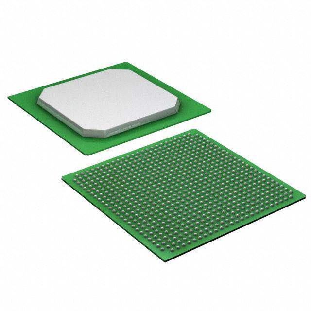
| 描述 | CONN RECEPT 100POS W/POSTS SMD |
| 产品分类 | 矩形 - 板对板连接器 - 阵列,边缘型,夹层式 |
| 品牌 | Hirose Electric Co Ltd |
| 数据手册 | |
| 产品图片 |
|
| 产品型号 | FX11LA-100S/10-SV(91) |
| rohs | 无铅 / 符合限制有害物质指令(RoHS)规范要求 |
| 产品系列 | FX11 |
| 产品培训模块 | http://www.digikey.cn/PTM/IndividualPTM.page?site=cn&lang=zhs&ptm=2734 |
| 产品目录绘图 |
|
| 其它名称 | H121970TR |
| 包装 | 带卷 (TR) |
| 安装类型 | 表面贴装 |
| 排数 | 2 |
| 接合堆叠高度 | 2mm |
| 板上高度 | 0.065"(1.65mm) |
| 标准包装 | 1,000 |
| 特性 | 板导轨,接地板,固定焊尾 |
| 触头镀层 | 金 |
| 触头镀层厚度 | 3.9µin (0.10µm) |
| 连接器类型 | 插座,中央带触点 |
| 配套产品 | /product-detail/zh/FX11LA-100P%2F10-SV(91)/H121964TR-ND/4036489/product-detail/zh/FX11LA-100P%2F10-SV(91)/H121964DKR-ND/4036480/product-detail/zh/FX11LA-100P%2F10-SV(91)/H121964CT-ND/4036479 |
| 针脚数 | 100 |
| 间距 | 0.020"(0.50mm) |


- 商务部:美国ITC正式对集成电路等产品启动337调查
- 曝三星4nm工艺存在良率问题 高通将骁龙8 Gen1或转产台积电
- 太阳诱电将投资9.5亿元在常州建新厂生产MLCC 预计2023年完工
- 英特尔发布欧洲新工厂建设计划 深化IDM 2.0 战略
- 台积电先进制程称霸业界 有大客户加持明年业绩稳了
- 达到5530亿美元!SIA预计今年全球半导体销售额将创下新高
- 英特尔拟将自动驾驶子公司Mobileye上市 估值或超500亿美元
- 三星加码芯片和SET,合并消费电子和移动部门,撤换高东真等 CEO
- 三星电子宣布重大人事变动 还合并消费电子和移动部门
- 海关总署:前11个月进口集成电路产品价值2.52万亿元 增长14.8%


PDF Datasheet 数据手册内容提取
0.5mm Pitch Connectors with Ground Plate for 2mm to 3mm High-Speed Board-to-Board Connections FX11 Series Stacking height : 2mm Stacking height : 2.5mm, 3mm d. e v r e s e R s ht g Ri All ■Features 10 Signal : 1 Ground Arrangement D. 1. Low Profile Design T The board-to-board mating height of 2mm, 2.5mm and 3mm suits L O., smaller, thinner case designs. (Fig.2) C 2. Improved Transmission Efficiency Between Boards C Transmission characteristics have been improved through a design Ground Plate Signal contact TRI that fixes ground plates to both sides of the header and receptacle. Housing 0.75mm C 3. 10 Signal:1 Ground Arrangement LE Signal and ground are arranged in a ratio of 10 : 1 with the ground plate connected to Metal fitting 0.5mm 0.75mm E E the board Via SMT. The ground stability achieved serves to reduce noise. (Fig.1) Ground plate and metal fitting make contact Fig.1 S 4. Metal Fittings for Added Strength O R Metal fittings provide for greater adhesion to the board, which Stacking Height Variation HI protects the connector against sheaning forces. The unique 8 connector design provides a connection between the fitting and the 01 ground plate for a stronger ground. (cid:39)(cid:35)(cid:21)(cid:42)(cid:33)(cid:40) 2 (cid:39)(cid:98)(cid:98) (cid:98)(cid:98) ht 5. Suited to High-Density Applications pyrig Tanhde rseidguncael sc omnotaucntt inpgit cshp aocf e0 o.5nm thme baoffaorrdd.s a compact connector, N o t e : 2w.0ithm tmhe t y2p.e5 mprmo dourc 3t .c0amnmno tty bpee upsroeddu ocrt .interchanFgeigd.2 o C 6. Structure Prevents Solder Wicking 8 A solder gap has been designed into the contact SMT portion to Structure Prevent Solder Wicking 1 0 prevent solder wicking. (Fig.3) 2 1. 7. High Contact Reliability (cid:72)(cid:100)(cid:97)(cid:89)(cid:90)(cid:103)(cid:21)(cid:92)(cid:86)(cid:101)(cid:21)(cid:101)(cid:100)(cid:103)(cid:105)(cid:94)(cid:100)(cid:99) ec. Effective wipe length is 0.55mm (2mm height) and 1mm(2.5mm, (cid:56)(cid:100)(cid:99)(cid:105)(cid:86)(cid:88)(cid:105) (cid:55)(cid:100)(cid:86)(cid:103)(cid:89)(cid:21)(cid:98)(cid:100)(cid:106)(cid:99)(cid:105)(cid:94)(cid:99)(cid:92)(cid:21)(cid:101)(cid:100)(cid:103)(cid:105)(cid:94)(cid:100)(cid:99) D 3mm height) for signal contacts. (cid:104)(cid:106)(cid:103)(cid:91)(cid:86)(cid:88)(cid:90) (cid:65)(cid:86)(cid:99)(cid:89) 8. Optional Ground Plate An alternate style is also available without the ground plate. The Fig.3 space provided by the absence of the ground plate is filled with additional signal contacts. ■ Signal Integrity Features ●Insertion-Loss-to-Crosstalk Ratio (ICR) Impedance 3mm(Without GND) The insertion-loss-to-crosstalk 120 ICR 3mm(Without GND) ratio (ICR) with five differential 60 115 FEXT aggressors meets the 50 110 extrapolated IEEE802.3ap specification to 10+ Gbps. 40 105 B) ø) 100 ●Differential Impedance CR(d30 Z( 95 I20 The differential impedance is 90 100 +/- 10ø for FX11 at 50 ps 10 85 rise time(20% to 80%). IIECEREspec FX11-3mm DifferentialTDR 0 80 0 1 2 3 4 5 6 7 8 9 10 0.8 0.9 1 1.1 1.2 1.3 1.4 1.5 Frequency(GHz) Time(ns) Ipnl ecaassee sc ownhtaecret ath ceo ampppalincya trieopnr ewsielln dteamtivaen fdo ar fhuirgthh eler vineflo orfm raetliiaobni.lity, such as automotive, 2017.11e 1
FX11 Series●0.5mm Pitch Connectors with Ground Plate for 2mm to 3mm High-Speed Board-to-Board Connections BStacking height variation ● With ground plate Receptacle Header FX11L#-*P / *-SV FX11L#-*S / *-SV 2mm Receptacle Header FX11#-*P / *-SV FX11#-*P / *-SV0.5 FX11#-*S / *-SV 2.5mm 3mm ● Without ground plate Receptacle Header FX11L#-*P-SV FX11L#-*S-SV 2mm d. e v er Receptacle Header FX11#-*P-SV FX11#-*P-SV0.5 s e FX11#-*S-SV 2.5mm 3mm R s ht Note 1: The thickness of the solder paste is not included in the stacking height. g Note 2: 2mm type and 2.5mm, 3mm type, with ground plate type and without ground type are not mated with each other. Ri All D. BCross section of mating T L O., ● Stacking height : 2mm C C RI E ELECT (cid:108)(cid:94)(cid:101)(cid:90)(cid:21)(cid:97)(cid:90)(cid:99)(cid:92)(cid:105)(cid:93)(cid:30) (cid:72)(cid:94)(cid:92)(cid:99)(cid:86)(cid:97)(cid:21)(cid:101)(cid:100)(cid:103)(cid:105)(cid:94)(cid:100)(cid:99) (cid:86)(cid:105)(cid:94)(cid:99)(cid:92)(cid:21)(cid:97)(cid:90)(cid:99)(cid:92)(cid:105)(cid:93)(cid:30) (cid:60)(cid:103)(cid:100)(cid:106)(cid:99)(cid:89)(cid:21)(cid:101)(cid:100)(cid:103)(cid:105)(cid:94)(cid:100)(cid:99) 8 HIROS (cid:42)(cid:29)(cid:58)(cid:91)(cid:91)(cid:90)(cid:88)(cid:105)(cid:94)(cid:107)(cid:90)(cid:21) (cid:29)(cid:58)(cid:91)(cid:91)(cid:90)(cid:88)(cid:105)(cid:94)(cid:107)(cid:90)(cid:21)(cid:98) (cid:61)(cid:90)(cid:86)(cid:89)(cid:90)(cid:103) 201 (cid:37)(cid:35)(cid:42) (cid:37)(cid:35)(cid:42)(cid:42) ht (cid:71)(cid:90)(cid:88)(cid:90)(cid:101)(cid:105)(cid:86)(cid:88)(cid:97)(cid:90) g ri y p o C 8 1 0 2 1. ● Stacking height : 2.5mm, 3mm c. e D (cid:107)(cid:90)(cid:21)(cid:108)(cid:94)(cid:101)(cid:90)(cid:21)(cid:97)(cid:90)(cid:99)(cid:92)(cid:105)(cid:93)(cid:30) (cid:72)(cid:94)(cid:92)(cid:99)(cid:86)(cid:97)(cid:21)(cid:101)(cid:100)(cid:103)(cid:105)(cid:94)(cid:100)(cid:99) (cid:90)(cid:21)(cid:98)(cid:86)(cid:105)(cid:94)(cid:99)(cid:92)(cid:21)(cid:97)(cid:90)(cid:99)(cid:92)(cid:105)(cid:93)(cid:30) (cid:60)(cid:103)(cid:100)(cid:106)(cid:99)(cid:89)(cid:21)(cid:101)(cid:100)(cid:103)(cid:105)(cid:94)(cid:100)(cid:99) (cid:61)(cid:90)(cid:86)(cid:89)(cid:90)(cid:103) (cid:90)(cid:88)(cid:105)(cid:94) (cid:88)(cid:105)(cid:94)(cid:107) (cid:29)(cid:58)(cid:91)(cid:91) (cid:58)(cid:91)(cid:91)(cid:90) (cid:38) (cid:29) (cid:46) (cid:37)(cid:35) (cid:71)(cid:90)(cid:88)(cid:90)(cid:101)(cid:105)(cid:86)(cid:88)(cid:97)(cid:90) (Shown for stacking height 2.5mm type.) 2
FX11 Series●0.5mm Pitch Connectors with Ground Plate for 2mm to 3mm High-Speed Board-to-Board Connections Stacking height : 2mm ■Product Specifications -55 to +85ç Rated current 0.3A Operating temperature range Storage temperature range -10 to +60ç (Note 1) Rating Relative humidity 95% or less Rated voltage 50V AC Operating humidity range Storage humidity range -40 to -70% (Note 1) (No condensation) Item Requirements Conditions 1. Insulation resistance 100Mø or greater Measured at 100V DC 2. Withstanding voltage No flashover or breakdown 150V AC applied for 1 minute 3. Contact resistance 60mø or less Measured at 100mA d. No electrical discontinuity for 1μs or greater Frequency : 10 to 55Hz, amplitude of 0.75mm e 4. Vibration resistance v No damaged, cracked or loose parts in 3 directions, 10 cycles each r e es No electrical discontinuity for 1μs or longer Acceleration of 490m/s2, 11ms duration, sine half-wave R 5. Shock resistance No damaged, cracked or loose parts waveform, for 3 cycles in the both directions of each of the 3 axes s ght 6. Humidity Contact resistance of 70mø or less, insulation resistance of Temperature of 40ç, humidity of 90 to 95%, Ri resistance 100Mø or greater, No damaged, cracked or loose parts duration 96h All → → → Contact resistance of 70mø or less, insulation resistance of Temperature : -55ç 15 to 35ç 85ç 15 to 35ç D. 7. Temperature cycle 100Mø or greater, No damaged, cracked or loose parts Time : 30 min. → 2 to 3 min. → 30 min. → 2 to 3 min. for 5 cycles T L O., 8. Mating cycles CNoon dtaacmt aregseids,t acnraccek oefd 7 o0rm loøo oser lpeassrts 50 times C C 9. Solder heat Reflow : At the recommended temperature profile RI No melting of resin portion which affects performance resistance Soldering iron temperature : 360ç for 5 seconds T C E Note 1 : The term “storage” refers to the long-term-storage status of unused items before mounting on the PCB. L E The operating temperature/humidity ranges apply to the unmated state after board mounting. E OS ■Materials / Finish R HI Part Material Finish Remarks 8 1 Insulator LCP Beige UL94V-0 0 2 Copper alloy Header Engagement Area : Gold plating of 0.1μm ht Contacts ---------- g Phosphor bronze Receptacle Termination Area : Flash plating ri py Ground plate Phosphor bronze Tin plating ---------- o C Metal fitting ---------- 8 Metal plate Phosphor bronze Tin plating ---------- 1 0 2 1. ■Product Number Structure c. e D Refer to the chart below when determining the product specifications from the product number. Please select from the product numbers listed in this catalog when placing orders. Type With Ground Plate FX11L # - * P - / * - SV (**) 1 2 4 5 6 3 Type Without Ground Plate FX11L # - * P - SV (**) 1 2 3 4 5 6 1 Series name : FX11L 4 Connector type 2 Form Symbol A : With guide post P : Header B : Without guide post S : Receptacle 3 Number of contactsType with ground plate 5 Contact form Signal/Ground : 60/6, 80/8, SV : Straight SMT 100/10, 120/12 6 Blank, (71) : Tray packaging (Without pick-and-place tape) Type without ground plate (21),(91) : E mbossed tape packaging (Without pick-and-place tape) Signal : 68, 92, 116, 140 (22),(92) : E mbossed tape packaging (With pick-and-place tape) 3
FX11 Series●0.5mm Pitch Connectors with Ground Plate for 2mm to 3mm High-Speed Board-to-Board Connections ■Header with Ground Plate (cid:54)(cid:164)(cid:37)(cid:35)(cid:39) ● 2mm stacking height (cid:29)(cid:37)(cid:35)(cid:42)(cid:30) (cid:37)(cid:35)(cid:39)(cid:164)(cid:37)(cid:35)(cid:37)(cid:42) (cid:42)(cid:35)(cid:39)(cid:42)(cid:164)(cid:37)(cid:35)(cid:40) (cid:42)(cid:35)(cid:37)(cid:42)(cid:164)(cid:37)(cid:35)(cid:39) (cid:38)(cid:35)(cid:39)(cid:164)(cid:37)(cid:35)(cid:39) (cid:172) (cid:29)(cid:37)(cid:35)(cid:44)(cid:42)(cid:30) (cid:29)(cid:37)(cid:35)(cid:44)(cid:42)(cid:30) (cid:29)(cid:43)(cid:30) (cid:55)(cid:164)(cid:37)(cid:35)(cid:39) (cid:56)(cid:164)(cid:37)(cid:35)(cid:40) (cid:40) (cid:37)(cid:35) (cid:164) (cid:40) (cid:43) (cid:38)(cid:35) d. e (cid:39)(cid:34)(cid:29)(cid:162)(cid:37)(cid:35)(cid:45)(cid:30) erv (cid:29)(cid:37)(cid:35)(cid:43)(cid:30) (cid:57)(cid:164)(cid:37)(cid:35)(cid:38) (cid:60)(cid:106)(cid:94)(cid:89)(cid:90)(cid:101)(cid:100)(cid:104)(cid:105) s e R Unit : mm s ght Part No. HRS No. No. of Contacts A B C D E F Remarks RoHS Ri Signal Ground All FX11LA-60P/6-SV(71) 573-0002-7 71 60 6 17.5 12 22.6 18 19.4 25.5 D. FX11LA-80P/8-SV(71) 573-0003-0 71 80 8 23.5 18 28.6 24 25.4 31.5 T With guideposts L FX11LA-100P/10-SV(71) 573-0004-2 71 100 10 29.5 24 34.6 30 31.4 37.5 O., FX11LA-120P/12-SV(71) 573-0005-5 71 120 12 35.5 30 40.6 36 37.4 43.5 C Yes C FX11LB-60P/6-SV(71) 573-0012-0 71 60 6 17.5 12 22.6 ---------- 19.4 25.5 RI FX11LB-80P/8-SV(71) 573-0013-3 71 80 8 23.5 18 28.6 ---------- 25.4 31.5 T Without guideposts C FX11LB-100P/10-SV(71) 573-0014-6 71 100 10 29.5 24 34.6 ---------- 31.4 37.5 E L FX11LB-120P/12-SV(71) 573-0015-9 71 120 12 35.5 30 40.6 ---------- 37.4 43.5 E E S [Specifications number] – **, (**) O R (71) : Tray packaging HI (91) : Embossed tape packaging (Without pick-and-place tape) 8 (92) : Embossed tape packaging (With pick-and-place tape) 1 0 2 Note 1 : There is no polarity in terms of board mounting for this product. ht Note 2 : The coplanarity of this product's SMT leads is 0.1 mm or less. g Note 3 : Please order embossed tape packaged items by the reel. (1,000 pcs/reel) ri y p o C 8 BRecommended Land Pattern Dimensions (Metal Mask Dimensions) 1 0 2 Recommended metal mask thickness: 0.15 mm 1. (cid:41) (cid:59)(cid:21)(cid:98)(cid:94)(cid:99) c. (cid:56)(cid:32)(cid:21)(cid:21)(cid:37)(cid:37)(cid:35)(cid:38) e D (cid:58)(cid:34)(cid:21)(cid:34)(cid:21)(cid:37)(cid:37)(cid:35)(cid:38) (cid:57)(cid:164)(cid:37)(cid:35)(cid:37)(cid:42) (cid:39) (cid:37)(cid:35)(cid:42)(cid:164)(cid:37)(cid:35)(cid:37)(cid:40) (cid:37)(cid:35)(cid:44)(cid:42)(cid:54)(cid:164)(cid:164)(cid:37)(cid:35)(cid:37)(cid:37)(cid:35)(cid:40)(cid:37)(cid:42) (cid:37)(cid:35)(cid:44)(cid:42)(cid:164)(cid:37)(cid:35)(cid:37)(cid:40) (cid:21)(cid:21)(cid:37)(cid:39)(cid:42)(cid:34)(cid:34)(cid:37)(cid:35)(cid:38) (cid:21)(cid:21)(cid:37)(cid:46)(cid:42)(cid:34)(cid:34)(cid:37)(cid:35)(cid:38) (cid:21)(cid:21)(cid:37)(cid:45)(cid:42)(cid:34)(cid:34)(cid:37)(cid:35)(cid:38) (cid:39)(cid:35) (cid:39)(cid:35) (cid:40)(cid:35) (cid:99) (cid:32)(cid:37)(cid:35)(cid:38)(cid:38)(cid:35)(cid:45)(cid:21)(cid:21)(cid:37) (cid:32)(cid:37)(cid:35)(cid:38)(cid:42)(cid:35)(cid:43)(cid:42)(cid:21)(cid:21)(cid:37) (cid:43)(cid:35)(cid:44)(cid:98)(cid:94)(cid:41) (cid:40) (cid:162)(cid:37)(cid:35)(cid:46)(cid:164)(cid:37)(cid:35)(cid:37)(cid:42) (cid:162)(cid:38)(cid:164)(cid:37)(cid:35)(cid:37)(cid:42) (cid:40) (cid:37)(cid:35)(cid:39)(cid:42)(cid:164)(cid:37)(cid:35)(cid:37)(cid:42) (cid:38) (cid:43)(cid:164)(cid:37)(cid:35)(cid:37)(cid:42) (cid:37)(cid:35)(cid:44)(cid:164)(cid:37)(cid:35)(cid:37)(cid:40)(cid:29)(cid:65)(cid:86)(cid:99)(cid:89)(cid:30) (cid:37)(cid:35)(cid:40)(cid:164)(cid:37)(cid:35)(cid:37)(cid:40)(cid:29)(cid:65)(cid:86)(cid:99)(cid:89)(cid:30) (cid:37)(cid:35)(cid:43)(cid:164)(cid:37)(cid:35)(cid:37)(cid:40)(cid:29)(cid:66)(cid:90)(cid:105)(cid:86)(cid:97)(cid:21)(cid:98)(cid:86)(cid:104)(cid:96)(cid:30) (cid:37)(cid:35)(cid:39)(cid:42)(cid:164)(cid:37)(cid:35)(cid:37)(cid:40)(cid:29)(cid:66)(cid:90)(cid:105)(cid:86)(cid:97)(cid:21)(cid:66)(cid:86)(cid:104)(cid:96)(cid:30) (cid:40)(cid:164)(cid:37)(cid:35)(cid:37)(cid:42) (cid:55)(cid:164)(cid:37)(cid:35)(cid:37)(cid:42) Note 1 Cross-hatched portions, totaling n places, indicate the ground circuits. 2 The cross-hatched area inside the SMT land may come into contact with the connector contacts and thus care should be taken that the pattern does not extend beyond the SMT land width. 3 Not required in products without guideposts. 4 Do not mount a part other than this product in the area of . Doing so will prevent the engagement of this and the mating connector. 4
FX11 Series●0.5mm Pitch Connectors with Ground Plate for 2mm to 3mm High-Speed Board-to-Board Connections ■Receptacle with Ground Plate (cid:54)(cid:164)(cid:37)(cid:35)(cid:39) ● 2mm stacking height (cid:29)(cid:37)(cid:35)(cid:42)(cid:30) (cid:37)(cid:35)(cid:42)(cid:164)(cid:37)(cid:35)(cid:37)(cid:42) (cid:37)(cid:35)(cid:39)(cid:164)(cid:37)(cid:35)(cid:37)(cid:42) (cid:43)(cid:35)(cid:39)(cid:164)(cid:37)(cid:35)(cid:40) (cid:43)(cid:164)(cid:37)(cid:35)(cid:39) (cid:38)(cid:35)(cid:39)(cid:164)(cid:37)(cid:35)(cid:39) (cid:29)(cid:37)(cid:35)(cid:44)(cid:42)(cid:30) (cid:29)(cid:37)(cid:35)(cid:44)(cid:42)(cid:30) (cid:29)(cid:43)(cid:30) (cid:37)(cid:35)(cid:40) (cid:55)(cid:164)(cid:37)(cid:35)(cid:39) (cid:164) (cid:42) (cid:56)(cid:164)(cid:37)(cid:35)(cid:40) (cid:43) (cid:38)(cid:35) d. e v (cid:39)(cid:34)(cid:29)(cid:162)(cid:37)(cid:35)(cid:45)(cid:30) er (cid:43)(cid:30) (cid:57)(cid:164)(cid:37)(cid:35)(cid:38) (cid:60)(cid:106)(cid:94)(cid:89)(cid:90)(cid:101)(cid:100)(cid:104)(cid:105) s (cid:37)(cid:35) e (cid:29) R Unit : mm s ght Part No. HRS No. No. of Contacts A B C D E F Remarks RoHS Ri Signal Ground All FX11LA-60S/6-SV(71) 573-0102-1 71 60 6 17.5 12 25 20.8 25.4 22.2 D. FX11LA-80S/8-SV(71) 573-0103-4 71 80 8 23.5 18 31 26.8 31.4 28.2 T With guideposts L FX11LA-100S/10-SV(71) 573-0104-7 71 100 10 29.5 24 37 32.8 37.4 34.2 O., FX11LA-120S/12-SV(71) 573-0105-0 71 120 12 35.5 30 43 38.8 43.4 40.2 C Yes C FX11LB-60S/6-SV(71) 573-0112-5 71 60 6 17.5 12 25 ---------- 25.4 22.2 RI FX11LB-80S/8-SV(71) 573-0113-8 71 80 8 23.5 18 31 ---------- 31.4 28.2 T Without guideposts C FX11LB-100S/10-SV(71) 573-0114-0 71 100 10 29.5 24 37 ---------- 37.4 34.2 E L FX11LB-120S/12-SV(71) 573-0115-3 71 120 12 35.5 30 43 ---------- 43.4 40.2 E E S [Specifications number] – **, (**) O R (71) : Tray packaging (Without pick-and-place tape) HI (91) : Embossed tape packaging (Without pick-and-place tape) 8 (92) : Embossed tape packaging (With pick-and-place tape) 1 0 2 Note 1 : There is no polarity in terms of board mounting for this product. ht Note 2 : The coplanarity of this product's SMT leads is 0.1 mm or less. g Note 3 : Please order embossed tape packaged items by the reel. (1,000 pcs/reel) ri y p o C 8 BRecommended Land Pattern Dimensions (Metal Mask Dimensions) 1 0 2 Recommended metal mask thickness: 0.15 mm 1. ec. (cid:58)(cid:32)(cid:21)(cid:21)(cid:37)(cid:37)(cid:35)(cid:38) D (cid:59)(cid:21)(cid:21)(cid:37) (cid:34)(cid:34)(cid:37)(cid:35)(cid:38) (cid:57)(cid:164)(cid:37)(cid:35)(cid:37)(cid:42) (cid:54)(cid:164)(cid:37)(cid:35)(cid:37)(cid:42) (cid:40) (cid:37)(cid:35)(cid:42)(cid:164)(cid:37)(cid:35)(cid:37)(cid:40) (cid:37)(cid:35)(cid:44)(cid:42)(cid:164)(cid:37)(cid:35)(cid:37)(cid:40) (cid:37)(cid:35)(cid:44)(cid:42)(cid:164)(cid:37)(cid:35)(cid:37)(cid:40) (cid:21)(cid:21)(cid:37)(cid:39)(cid:34)(cid:34)(cid:37)(cid:35)(cid:38) (cid:39)(cid:35) (cid:32)(cid:37)(cid:35)(cid:38)(cid:38)(cid:35)(cid:45)(cid:21)(cid:21)(cid:37) (cid:21)(cid:21)(cid:37)(cid:41)(cid:34)(cid:34)(cid:37)(cid:35)(cid:38) (cid:21)(cid:21)(cid:37)(cid:41)(cid:35)(cid:45)(cid:34)(cid:34)(cid:37)(cid:35)(cid:38) (cid:32)(cid:37)(cid:35)(cid:38)(cid:43)(cid:35)(cid:43)(cid:21)(cid:21)(cid:37) (cid:39) (cid:41) (cid:162)(cid:37)(cid:35)(cid:46)(cid:164)(cid:37)(cid:35)(cid:37)(cid:42) (cid:162)(cid:38)(cid:164)(cid:37)(cid:35)(cid:37)(cid:42) (cid:41) (cid:38)(cid:35)(cid:43)(cid:42)(cid:164)(cid:37)(cid:35)(cid:37)(cid:42) (cid:38) (cid:43)(cid:164)(cid:37)(cid:35)(cid:37)(cid:42) (cid:37)(cid:35)(cid:44)(cid:164)(cid:37)(cid:35)(cid:37)(cid:40)(cid:29)(cid:65)(cid:86)(cid:99)(cid:89)(cid:30) (cid:37)(cid:35)(cid:40)(cid:164)(cid:37)(cid:35)(cid:37)(cid:40)(cid:29)(cid:65)(cid:86)(cid:99)(cid:89)(cid:30) (cid:37)(cid:35)(cid:43)(cid:164)(cid:37)(cid:35)(cid:37)(cid:40)(cid:29)(cid:66)(cid:90)(cid:105)(cid:86)(cid:97)(cid:21)(cid:98)(cid:86)(cid:104)(cid:96)(cid:30) (cid:37)(cid:35)(cid:39)(cid:42)(cid:164)(cid:37)(cid:35)(cid:37)(cid:40)(cid:29)(cid:66)(cid:90)(cid:105)(cid:86)(cid:97)(cid:21)(cid:98)(cid:86)(cid:104)(cid:96)(cid:30) (cid:41)(cid:35)(cid:41)(cid:164)(cid:37)(cid:35)(cid:37)(cid:42) (cid:55)(cid:164)(cid:37)(cid:35)(cid:37)(cid:42) Note 1 Cross-hatched portions, totaling n places, indicate the ground circuits. 2 Cross-hatched portions, 2 places on both sides, indicate the metal fittings. 3 The cross-hatched area inside the SMT land may come into contact with the connector contacts and thus care should be taken that the pattern does not extend beyond the SMT land width. 4 Not required in products without guideposts. 5
FX11 Series●0.5mm Pitch Connectors with Ground Plate for 2mm to 3mm High-Speed Board-to-Board Connections ■Header without Ground Plate (cid:54)(cid:164)(cid:37)(cid:35)(cid:39) ● 2mm stacking height (cid:29)(cid:37)(cid:35)(cid:42)(cid:30) (cid:37)(cid:35)(cid:39)(cid:164)(cid:37)(cid:35)(cid:37)(cid:42) (cid:164)(cid:37)(cid:35)(cid:40) (cid:164)(cid:37)(cid:35)(cid:39) (cid:164)(cid:37)(cid:35)(cid:39) (cid:42)(cid:35)(cid:39)(cid:42) (cid:42)(cid:35)(cid:37)(cid:42) (cid:38)(cid:35)(cid:39) (cid:55)(cid:164)(cid:37)(cid:35)(cid:40) (cid:164)(cid:37)(cid:35)(cid:40) (cid:38)(cid:35)(cid:43)(cid:40) d. e (cid:39)(cid:34)(cid:29)(cid:162)(cid:37)(cid:35)(cid:45)(cid:30) erv (cid:37)(cid:35)(cid:43)(cid:30) (cid:56)(cid:164)(cid:37)(cid:35)(cid:38) (cid:60)(cid:106)(cid:94)(cid:89)(cid:90)(cid:101)(cid:100)(cid:104)(cid:105) s (cid:29) e R Unit : mm s ght Part No. HRS No. No. of Contacts A B C D E Remarks RoHS Ri Signal All FX11LA-68P-SV(**) 573-0042-1 ** 68 16.5 22.6 18 19.4 25.5 D. FX11LA-92P-SV(**) 573-0043-4 ** 92 22.5 28.6 24 25.4 31.5 T With guideposts L FX11LA-116P-SV(**) 573-0044-7 ** 116 28.5 34.6 30 31.4 37.5 O., FX11LA-140P-SV(**) 573-0045-0 ** 140 34.5 40.6 36 37.4 43.5 C Yes C FX11LB-68P-SV(**) 573-0052-5 ** 68 16.5 22.6 ---------- 19.4 25.5 RI FX11LB-92P-SV(**) 573-0053-8 ** 92 22.5 28.6 ---------- 25.4 31.5 T Without guideposts C FX11LB-116P-SV(**) 573-0054-0 ** 116 28.5 34.6 ---------- 31.4 37.5 E L FX11LB-140P-SV(**) 573-0055-3 ** 140 34.5 40.6 ---------- 37.4 43.5 E E S [Specifications number] – **, (**) O R Blank : Tray packaging (Without pick-and-place tape) HI (21) : Embossed tape packaging (Without pick-and-place tape) 8 (22) : Embossed tape packaging (With pick-and-place tape) 1 0 2 Note 1 : There is no polarity in terms of board mounting for this product. ht Note 2 : The coplanarity of this product's SMT leads is 0.1 mm or less. g Note 3 : Please order embossed tape packaged items by the reel. (1,000 pcs/reel) ri y p o C 8 BRecommended Land Pattern Dimensions (Metal Mask Dimensions) 1 0 2 Recommended metal mask thickness: 0.15 mm 1. (cid:40) (cid:58)(cid:21)(cid:98)(cid:94)(cid:99) ec. (cid:55)(cid:32)(cid:21)(cid:21)(cid:37)(cid:37)(cid:35)(cid:38) D (cid:57)(cid:21)(cid:21)(cid:37) (cid:34)(cid:34)(cid:37)(cid:35)(cid:38) (cid:56)(cid:164)(cid:37)(cid:35)(cid:37)(cid:42) (cid:38) (cid:37)(cid:35)(cid:42)(cid:164)(cid:37)(cid:35)(cid:37)(cid:40) (cid:54)(cid:164)(cid:37)(cid:35)(cid:37)(cid:42) (cid:21)(cid:21)(cid:37)(cid:39)(cid:42)(cid:34)(cid:34)(cid:37)(cid:35)(cid:38) (cid:21)(cid:21)(cid:37)(cid:45)(cid:42)(cid:34)(cid:34)(cid:37)(cid:35)(cid:38) (cid:39)(cid:35) (cid:40)(cid:35) (cid:99) (cid:32)(cid:37)(cid:35)(cid:38)(cid:38)(cid:35)(cid:45)(cid:21)(cid:21)(cid:37) (cid:32)(cid:37)(cid:35)(cid:38)(cid:42)(cid:35)(cid:43)(cid:42)(cid:21)(cid:21)(cid:37) (cid:43)(cid:35)(cid:44)(cid:98)(cid:94)(cid:40) (cid:39) (cid:162)(cid:37)(cid:35)(cid:46)(cid:164)(cid:37)(cid:35)(cid:37)(cid:42) (cid:162)(cid:38)(cid:164)(cid:37)(cid:35)(cid:37)(cid:42) (cid:39) (cid:37)(cid:35)(cid:44)(cid:42)(cid:164)(cid:37)(cid:35)(cid:37)(cid:42) (cid:37)(cid:35)(cid:40)(cid:164)(cid:37)(cid:35)(cid:37)(cid:40)(cid:29)(cid:65)(cid:86)(cid:99)(cid:89)(cid:30) (cid:37)(cid:35)(cid:39)(cid:42)(cid:164)(cid:37)(cid:35)(cid:37)(cid:40)(cid:29)(cid:66)(cid:90)(cid:105)(cid:86)(cid:97)(cid:21)(cid:98)(cid:86)(cid:104)(cid:96)(cid:30) Note 1 T he cross-hatched area inside the SMT land may come into contact with the connector contacts and thus care should be taken that the pattern does not extend beyond the SMT land width. 2 Not required in products without guideposts. 3 Do not mount a part other than this product in the area of . Doing so will prevent the engagement of this and the mating connector. 6
FX11 Series●0.5mm Pitch Connectors with Ground Plate for 2mm to 3mm High-Speed Board-to-Board Connections ■Receptacle without Ground Plate (cid:54)(cid:164)(cid:37)(cid:35)(cid:39) ● 2mm stacking height (cid:55)(cid:164)(cid:37)(cid:35)(cid:39) (cid:29)(cid:37)(cid:35)(cid:42)(cid:30) (cid:37)(cid:35)(cid:39)(cid:164)(cid:37)(cid:35)(cid:37)(cid:42) (cid:37)(cid:35)(cid:42)(cid:164)(cid:37)(cid:35)(cid:37)(cid:42) (cid:43)(cid:35)(cid:39)(cid:164)(cid:37)(cid:35)(cid:40) (cid:43)(cid:164)(cid:37)(cid:35)(cid:39) (cid:40) (cid:37)(cid:35) (cid:164) (cid:42) (cid:56)(cid:164)(cid:37)(cid:35)(cid:40) (cid:43) (cid:38)(cid:35) d. e v er (cid:43)(cid:30) (cid:57)(cid:164)(cid:37)(cid:35)(cid:38) (cid:60)(cid:106)(cid:94)(cid:89)(cid:90)(cid:101)(cid:100)(cid:104)(cid:105) s (cid:37)(cid:35) e (cid:29) R Unit : mm s ght Part No. HRS No. No. of Contacts A B C D Remarks RoHS Ri Signal All FX11LA-68S-SV(**) 573-0142-6 ** 68 18 16.5 25 20.8 D. FX11LA-92S-SV(**) 573-0143-9 ** 92 24 22.5 31 26.8 T With guideposts L FX11LA-116S-SV(**) 573-0144-1 ** 116 30 28.5 37 32.8 O., FX11LA-140S-SV(**) 573-0145-4 ** 140 36 34.5 43 38.8 C Yes C FX11LB-68S-SV(**) 573-0152-0 ** 68 18 16.5 25 ---------- RI FX11LB-92S-SV(**) 573-0153-2 ** 92 24 22.5 31 ---------- T Without guideposts C FX11LB-116S-SV(**) 573-0154-5 ** 116 30 28.5 37 ---------- E L FX11LB-140S-SV(**) 573-0155-8 ** 140 36 34.5 43 ---------- E E S [Specifications number] – **, (**) O R Blank : Tray packaging (Without pick-and-place tape) HI (21) : Embossed tape packaging (Without pick-and-place tape) 8 (22) : Embossed tape packaging (With pick-and-place tape) 1 0 2 Note 1 : There is no polarity in terms of board mounting for this product. ht Note 2 : The coplanarity of this product's SMT leads is 0.1 mm or less. g Note 3 : Please order embossed tape packaged items by the reel. (1,000 pcs/reel) ri y p o C 8 BRecommended Land Pattern Dimensions (Metal Mask Dimensions) 1 0 2 Recommended metal mask thickness: 0.15 mm 1. c. (cid:57)(cid:164)(cid:37)(cid:35)(cid:37)(cid:42) e D (cid:54)(cid:164)(cid:37)(cid:35)(cid:37)(cid:42) (cid:55)(cid:164)(cid:37)(cid:35)(cid:37)(cid:42) (cid:38) (cid:37)(cid:35)(cid:42)(cid:164)(cid:37)(cid:35)(cid:37)(cid:40) (cid:21)(cid:21)(cid:37)(cid:39)(cid:34)(cid:34)(cid:37)(cid:35)(cid:38) (cid:39)(cid:35) (cid:21)(cid:21)(cid:37)(cid:41)(cid:34)(cid:34)(cid:37)(cid:35)(cid:38) (cid:21)(cid:21)(cid:37)(cid:41)(cid:35)(cid:45)(cid:34)(cid:34)(cid:37)(cid:35)(cid:38) (cid:32)(cid:37)(cid:35)(cid:38)(cid:43)(cid:35)(cid:43)(cid:21)(cid:21)(cid:37) (cid:39) (cid:162)(cid:37)(cid:35)(cid:46)(cid:164)(cid:37)(cid:35)(cid:37)(cid:42) (cid:162)(cid:38)(cid:164)(cid:37)(cid:35)(cid:37)(cid:42) (cid:39) (cid:39)(cid:35)(cid:38)(cid:42)(cid:164)(cid:37)(cid:35)(cid:37)(cid:42) (cid:37)(cid:35)(cid:44)(cid:164)(cid:37)(cid:35)(cid:37)(cid:40)(cid:29)(cid:65)(cid:86)(cid:99)(cid:89)(cid:30) (cid:37)(cid:35)(cid:40)(cid:164)(cid:37)(cid:35)(cid:37)(cid:40)(cid:29)(cid:65)(cid:86)(cid:99)(cid:89)(cid:30) (cid:37)(cid:35)(cid:43)(cid:164)(cid:37)(cid:35)(cid:37)(cid:40)(cid:29)(cid:66)(cid:90)(cid:105)(cid:86)(cid:97)(cid:21)(cid:98)(cid:86)(cid:104)(cid:96)(cid:30) (cid:37)(cid:35)(cid:39)(cid:42)(cid:164)(cid:37)(cid:35)(cid:37)(cid:40)(cid:29)(cid:66)(cid:90)(cid:105)(cid:86)(cid:97)(cid:21)(cid:98)(cid:86)(cid:104)(cid:96)(cid:30) Note 1 T he cross-hatched area inside the SMT land may come into contact with the connector contacts and thus care should be taken that the pattern does not extend beyond the SMT land width. 2 Not required in products without guideposts. 7
FX11 Series●0.5mm Pitch Connectors with Ground Plate for 2mm to 3mm High-Speed Board-to-Board Connections Stacking height : 2.5mm, 3mm ■Product Specifications -55 to +85ç Rated current 0.3A Operating temperature range Storage temperature range -10 to +60ç (Note 1) Rating Relative humidity 95% or less Rated voltage 50V AC Operating humidity range Storage humidity range -40 to -70% (Note 1) (No condensation) Item Requirements Conditions 1. Insulation resistance 100Mø or greater Measured at 100V DC 2. Withstanding voltage No flashover or breakdown 150V AC applied for 1 minute 3. Contact resistance 70mø or less Measured at 100mA d. No electrical discontinuity for 1μs or greater Frequency : 10 to 55Hz, amplitude of 0.75mm e 4. Vibration resistance v No damaged, cracked or loose parts in 3 directions,10 cycles each r e s e No electrical discontinuity for 1μs or longer Acceleration of 490m/s2, 11ms duration, sine half-wave R 5. Shock resistance s No damaged, cracked or loose parts waveform, for 3 cycles in the both directions of each of the 3 axes ht g Contact resistance of 80mø or less, insulation resistance Temperature of 40ç, humidity of 90 to 95%, Ri 6. Humidity resistance of 100Mø or greater, No damaged, cracked or loose parts duration 96h All → → → D. 7. Temperature cycle Contact resistance of 80mø or less, insulation resistance Temperature : →-55ç 15 to→ 35ç 85→ç 15 to 35ç T of 100Mø or greater, No damaged, cracked or loose parts Time : 30 min. 2 to 3 min. 30 min. 2 to 3 min. for 5 cycles L O., 8. Mating cycles Contact resistance of 80mø or less 50 times C No damaged, cracked or loose parts C RI 9. Solder heat resistance No melting of resin portion which affects Reflow : At the recommended temperature profile T performance Soldering iron temperature : 360ç for 5 seconds C E Note 1 : The term “storage” refers to the long-term-storage status of unused items before mounting on the PCB. L E The operating temperature/humidity ranges apply to the unmated state after board mounting. E OS ■Materials / Finish R HI Part Material Finish Remarks 8 1 Insulator LCP Beige UL94V-0 0 ht 2 Contacts Copper alloy Header Engagement Area : Gold plating of 0.1μm ---------- g Phosphor bronze Receptacle Termination Area : Flash plating ri y p Ground plate Phosphor bronze Tin plating ---------- o C Metal fitting ---------- 18 Metal plate Phosphor bronze Tin plating ---------- 0 2 1. c. ■Product Number Structure e D Refer to the chart below when determining the product specifications from the product number. Please select from the product numbers listed in this catalog when placing orders. Type With Ground Plate FX11 # - * P / * - SV 0.5 (**) ❶ ❷ ❹ ❺ ❻ ❼ ❸ Type Without Ground Plate FX11 # - * P - SV 0.5 (**) ❶ ❷ ❸ ❹ ❺ ❻ ❼ ❶ Series name : FX11 ❹ Connector type P : Header ❷ Form Symbol A : With guide post S : Receptacle B : Without guide post ❺ Contact form SV : Straight SMT ❸ Number of contactsType with ground plate ❻ Product height Signal/Ground:60/6, Blank : Standard 0.5 : Standard + 0.5mm 80/8, 100/10 ❼ Blank, (71) : Tray packaging (Without pick-and-place tape) Type without ground plate (21),(91) : E mbossed tape packaging (Without pick-and-place tape) Signal : 80, 100 (22),(92) : E mbossed tape packaging (With pick-and-place tape) 8
FX11 Series●0.5mm Pitch Connectors with Ground Plate for 2mm to 3mm High-Speed Board-to-Board Connections ■Header with Ground Plate (cid:54)(cid:164)(cid:37)(cid:35)(cid:39) ● 2.5mm stacking height (cid:29)(cid:37)(cid:35)(cid:42)(cid:30) (cid:37)(cid:35)(cid:42)(cid:164)(cid:37)(cid:35)(cid:37)(cid:42) (cid:37)(cid:35)(cid:39)(cid:164)(cid:37)(cid:35)(cid:37)(cid:42) (cid:42)(cid:35)(cid:39)(cid:42)(cid:164)(cid:37)(cid:35)(cid:40) (cid:42)(cid:35)(cid:37)(cid:42)(cid:164)(cid:37)(cid:35)(cid:39) (cid:38)(cid:35)(cid:39)(cid:164)(cid:37)(cid:35)(cid:39) (cid:29)(cid:37)(cid:35)(cid:44)(cid:42)(cid:30) (cid:29)(cid:37)(cid:35)(cid:44)(cid:42)(cid:30) (cid:29)(cid:43)(cid:30) (cid:55)(cid:164)(cid:37)(cid:35)(cid:39) (cid:40) (cid:37)(cid:35) (cid:56)(cid:164)(cid:37)(cid:35)(cid:40) (cid:164) (cid:40) (cid:38) d. (cid:39)(cid:35) e v r e Res (cid:29)(cid:37)(cid:35)(cid:43)(cid:30) (cid:39)(cid:34)(cid:29)(cid:162)(cid:37)(cid:35)(cid:45)(cid:30) (cid:60)(cid:106)(cid:94)(cid:89)(cid:90)(cid:101)(cid:100)(cid:104)(cid:105) s (cid:57)(cid:164)(cid:37)(cid:35)(cid:38) ht Unit : mm g Ri No. of Contacts All Part No. HRS No. Signal Ground A B C D E F Remarks RoHS D. FX11A-60P/06-SV(71) 573-0502-0 71 60 6 17.5 12 22.6 18 19.4 25.5 T L O., FX11A-80P/08-SV(71) 573-0503-2 71 80 8 23.5 18 28.6 24 25.4 31.5 With guideposts C FX11A-100P/10-SV(71) 573-0504-5 71 100 10 29.5 24 34.6 30 31.4 37.5 Yes C FX11B-60P/06-SV(71) 573-0512-3 71 60 6 17.5 12 22.6 ---------- 19.4 25.5 RI T FX11B-80P/08-SV(71) 573-0513-6 71 80 8 23.5 18 28.6 ---------- 25.4 31.5 Without guideposts C E FX11B-100P/10-SV(71) 573-0514-9 71 100 10 29.5 24 34.6 ---------- 31.4 37.5 L E E [Specifications number] – **, (**) S O (71) : Tray packaging (Without pick-and-place tape) R (91) : Embossed tape packaging (Without pick-and-place tape) HI (92) : Embossed tape packaging (With pick-and-place tape) 8 01 Note 1 : There is no polarity in terms of board mounting for this product. 2 Note 2 : The coplanarity of this product's SMT leads is 0.1 mm or less. ht Note 3 : Please order embossed tape packaged items by the reel. (1,000 pcs/reel) g ri y p o BRecommended Land Pattern Dimensions (Metal Mask Dimensions) C 8 Recommended metal mask thickness: 0.15 mm 01 (cid:41) (cid:59)(cid:21)(cid:98)(cid:94)(cid:99) 1.2 (cid:56)(cid:32)(cid:21)(cid:37)(cid:37)(cid:35)(cid:38) ec. (cid:58)(cid:21)(cid:21)(cid:37) D (cid:57)(cid:164)(cid:37)(cid:35)(cid:37)(cid:42) (cid:54)(cid:164)(cid:37)(cid:35)(cid:37)(cid:42) (cid:39) (cid:37)(cid:35)(cid:42)(cid:164)(cid:37)(cid:35)(cid:37)(cid:40) (cid:21)(cid:37)(cid:42)(cid:34)(cid:37)(cid:35)(cid:38) (cid:21)(cid:37)(cid:42)(cid:34)(cid:37)(cid:35)(cid:38) (cid:21)(cid:37)(cid:42)(cid:34)(cid:37)(cid:35)(cid:38) (cid:37)(cid:35)(cid:44)(cid:42)(cid:164)(cid:37)(cid:35)(cid:37)(cid:40) (cid:37)(cid:35)(cid:44)(cid:42)(cid:164)(cid:37)(cid:35)(cid:37)(cid:40) (cid:39) (cid:46) (cid:45) (cid:39)(cid:35) (cid:39)(cid:35) (cid:40)(cid:35) (cid:32)(cid:37)(cid:35)(cid:38)(cid:38)(cid:35)(cid:45)(cid:21)(cid:37) (cid:32)(cid:37)(cid:35)(cid:38)(cid:42)(cid:35)(cid:43)(cid:42)(cid:21)(cid:37) (cid:43)(cid:35)(cid:44)(cid:21)(cid:98)(cid:94)(cid:99) (cid:40) (cid:162)(cid:37)(cid:35)(cid:46)(cid:164)(cid:37)(cid:35)(cid:37)(cid:42) (cid:162)(cid:38)(cid:164)(cid:37)(cid:35)(cid:37)(cid:42) (cid:40) (cid:41) (cid:37)(cid:35)(cid:39)(cid:42)(cid:164)(cid:37)(cid:35)(cid:37)(cid:42) (cid:38) (cid:43)(cid:164)(cid:37)(cid:35)(cid:37)(cid:42) (cid:37)(cid:35)(cid:44)(cid:21)(cid:164)(cid:37)(cid:35)(cid:37)(cid:40)(cid:29)(cid:65)(cid:86)(cid:99)(cid:89)(cid:30) (cid:37)(cid:35)(cid:40)(cid:164)(cid:37)(cid:35)(cid:37)(cid:40)(cid:29)(cid:65)(cid:86)(cid:99)(cid:89)(cid:30) (cid:37)(cid:35)(cid:43)(cid:164)(cid:37)(cid:35)(cid:37)(cid:40)(cid:29)(cid:66)(cid:90)(cid:105)(cid:86)(cid:97)(cid:21)(cid:98)(cid:86)(cid:104)(cid:96)(cid:30) (cid:37)(cid:35)(cid:39)(cid:42)(cid:164)(cid:37)(cid:35)(cid:37)(cid:40)(cid:29)(cid:66)(cid:90)(cid:105)(cid:86)(cid:97)(cid:21)(cid:98)(cid:86)(cid:104)(cid:96)(cid:30) (cid:40)(cid:164)(cid:37)(cid:35)(cid:37)(cid:42) (cid:55)(cid:164)(cid:37)(cid:35)(cid:37)(cid:42) Note 11 Cross-hatched portions, totaling n places, indicate the ground circuits. 22 The cross-hatched area inside the SMT land may come into contact with the connector contacts and thus care should be taken that the pattern does not extend beyond the SMT land width. 33 Not required in products without guideposts. 44 Do not mount a part other than this product in the area of . Doing so will prevent the engagement of this and the mating connector. 9
FX11 Series●0.5mm Pitch Connectors with Ground Plate for 2mm to 3mm High-Speed Board-to-Board Connections ■Header with Ground Plate (cid:54)(cid:164)(cid:37)(cid:35)(cid:39) (cid:29)(cid:37)(cid:35)(cid:42)(cid:30) (cid:37)(cid:35)(cid:42)(cid:164)(cid:37)(cid:35)(cid:37)(cid:42) ● 3mm stacking height (cid:37)(cid:35)(cid:39)(cid:164)(cid:37)(cid:35)(cid:37)(cid:42) (cid:42)(cid:35)(cid:39)(cid:42)(cid:164)(cid:37)(cid:35)(cid:40) (cid:42)(cid:35)(cid:37)(cid:42)(cid:164)(cid:37)(cid:35)(cid:39) (cid:38)(cid:35)(cid:39)(cid:164)(cid:37)(cid:35)(cid:39) (cid:29)(cid:37)(cid:35)(cid:44)(cid:42)(cid:30) (cid:29)(cid:37)(cid:35)(cid:44)(cid:42)(cid:30) (cid:29)(cid:43)(cid:30) (cid:55)(cid:164)(cid:37)(cid:35)(cid:39) (cid:40) (cid:37)(cid:35) (cid:56)(cid:164)(cid:37)(cid:35)(cid:40) (cid:164) (cid:40) (cid:43) (cid:39)(cid:35) d. e v ser (cid:37)(cid:35)(cid:43)(cid:30) (cid:39)(cid:34)(cid:29)(cid:162)(cid:37)(cid:35)(cid:45)(cid:30) (cid:60)(cid:106)(cid:94)(cid:89)(cid:90)(cid:101)(cid:100)(cid:104)(cid:105) e (cid:29) R s (cid:57)(cid:164)(cid:37)(cid:35)(cid:38) ht Unit : mm g Ri No. of Contacts All Part No. HRS No. Signal Ground A B C D E F Remarks RoHS D. FX11A-60P/6-SV0.5(71) 573-0602-4 71 60 6 17.5 12 22.6 18 19.4 25.5 T With L O., FX11A-80P/8-SV0.5(71) 573-0603-7 71 80 8 23.5 18 28.6 24 25.4 31.5 guideposts C FX11A-100P/10-SV0.5(71) 573-0604-0 71 100 10 29.5 24 34.6 30 31.4 37.5 Yes C FX11B-60P/6-SV0.5(71) 573-0612-8 71 60 6 17.5 12 22.6 ---------- 19.4 25.5 RI Without T FX11B-80P/8-SV0.5(71) 573-0613-0 71 80 8 23.5 18 28.6 ---------- 25.4 31.5 C guideposts E FX11B-100P/10-SV0.5(71) 573-0614-3 71 100 10 29.5 24 34.6 ---------- 31.4 37.5 L E E [Specifications number] – **, (**) S O (71) : Tray packaging (Without pick-and-place tape) R (91) : Embossed tape packaging (Without pick-and-place tape) HI (92) : Embossed tape packaging (With pick-and-place tape) 8 01 Note 1 : There is no polarity in terms of board mounting for this product. 2 Note 2 : The coplanarity of this product's SMT leads is 0.1 mm or less. ht Note 3 : Please order embossed tape packaged items by the reel. (1,000 pcs/reel) g ri y p o BRecommended Land Pattern Dimensions (Metal Mask Dimensions) C 8 Recommended metal mask thickness: 0.15 mm 1 (cid:41) (cid:59)(cid:98)(cid:94)(cid:99) 0 1.2 (cid:56)(cid:32)(cid:21)(cid:37)(cid:37)(cid:35)(cid:38) ec. (cid:58)(cid:34)(cid:21)(cid:37)(cid:37)(cid:35)(cid:38) D (cid:57)(cid:164)(cid:37)(cid:35)(cid:37)(cid:42) (cid:54)(cid:164)(cid:37)(cid:35)(cid:37)(cid:42) (cid:39) (cid:37)(cid:37)(cid:35)(cid:35)(cid:44)(cid:42)(cid:42)(cid:164)(cid:164)(cid:37)(cid:37)(cid:35)(cid:37)(cid:35)(cid:37)(cid:40)(cid:40) (cid:37)(cid:35)(cid:44)(cid:42)(cid:164)(cid:37)(cid:35)(cid:37)(cid:40) (cid:21)(cid:37)(cid:39)(cid:42)(cid:34)(cid:37)(cid:35)(cid:38) (cid:21)(cid:37)(cid:46)(cid:42)(cid:34)(cid:37)(cid:35)(cid:38) (cid:21)(cid:37)(cid:45)(cid:42)(cid:34)(cid:37)(cid:35)(cid:38) (cid:39)(cid:35) (cid:39)(cid:35) (cid:40)(cid:35) (cid:32)(cid:37)(cid:35)(cid:38)(cid:38)(cid:35)(cid:45)(cid:21)(cid:37) (cid:32)(cid:37)(cid:35)(cid:38)(cid:42)(cid:35)(cid:43)(cid:42)(cid:21)(cid:37) (cid:43)(cid:35)(cid:44)(cid:21)(cid:98)(cid:94)(cid:99) (cid:40) (cid:162)(cid:37)(cid:35)(cid:46)(cid:164)(cid:37)(cid:35)(cid:37)(cid:42) (cid:162)(cid:38)(cid:164)(cid:37)(cid:35)(cid:37)(cid:42) (cid:40) (cid:41) (cid:37)(cid:35)(cid:39)(cid:42)(cid:164)(cid:37)(cid:35)(cid:37)(cid:42) (cid:38) (cid:43)(cid:164)(cid:37)(cid:35)(cid:37)(cid:42) (cid:37)(cid:35)(cid:44)(cid:164)(cid:37)(cid:35)(cid:37)(cid:40)(cid:29)(cid:65)(cid:86)(cid:99)(cid:89)(cid:30) (cid:37)(cid:35)(cid:40)(cid:164)(cid:37)(cid:35)(cid:37)(cid:40)(cid:29)(cid:65)(cid:86)(cid:99)(cid:89)(cid:30) (cid:37)(cid:35)(cid:43)(cid:164)(cid:37)(cid:35)(cid:37)(cid:40)(cid:29)(cid:66)(cid:90)(cid:105)(cid:86)(cid:97)(cid:21)(cid:98)(cid:86)(cid:104)(cid:96)(cid:30) (cid:37)(cid:35)(cid:39)(cid:42)(cid:164)(cid:37)(cid:35)(cid:37)(cid:40)(cid:29)(cid:66)(cid:90)(cid:105)(cid:86)(cid:97)(cid:21)(cid:98)(cid:86)(cid:104)(cid:96)(cid:30) (cid:40)(cid:164)(cid:37)(cid:35)(cid:37)(cid:42) (cid:55)(cid:164)(cid:37)(cid:35)(cid:37)(cid:42) Note 1 Cross-hatched portions, totaling n places, indicate the ground circuits. 2 The cross-hatched area inside the SMT land may come into contact with the connector contacts and thus care should be taken that the pattern does not extend beyond the SMT land width. 3 Not required in products without guideposts. 4 Do not mount a part other than this product in the area of . Doing so will prevent the engagement of this and the mating connector. 10
FX11 Series●0.5mm Pitch Connectors with Ground Plate for 2mm to 3mm High-Speed Board-to-Board Connections ■Receptacle with Ground Plate (cid:54)(cid:164)(cid:37)(cid:35)(cid:39) ● 2.5mm, 3mm stacking height (cid:29)(cid:37)(cid:35)(cid:42)(cid:30) (cid:37)(cid:35)(cid:42)(cid:164)(cid:37)(cid:35)(cid:37)(cid:42) (cid:37)(cid:35)(cid:39)(cid:164)(cid:37)(cid:35)(cid:37)(cid:42) (cid:43)(cid:35)(cid:39)(cid:164)(cid:37)(cid:35)(cid:40) (cid:43)(cid:164)(cid:37)(cid:35)(cid:39) (cid:38)(cid:35)(cid:39)(cid:164)(cid:37)(cid:35)(cid:39) (cid:29)(cid:37)(cid:35)(cid:44)(cid:42)(cid:30) (cid:29)(cid:37)(cid:35)(cid:44)(cid:42)(cid:30) (cid:29)(cid:43)(cid:30) (cid:55)(cid:164)(cid:37)(cid:35)(cid:39) (cid:37)(cid:35)(cid:40) (cid:56)(cid:164)(cid:37)(cid:35)(cid:40) (cid:164) (cid:38) d. (cid:39)(cid:35) e v r e s (cid:43)(cid:30) Re (cid:29)(cid:37)(cid:35) (cid:39)(cid:34)(cid:29)(cid:162)(cid:37)(cid:35)(cid:45)(cid:30) (cid:60)(cid:106)(cid:94)(cid:89)(cid:90)(cid:101)(cid:100)(cid:104)(cid:105) s (cid:57)(cid:164)(cid:37)(cid:35)(cid:38) ht Unit : mm g Ri No. of Contacts All Part No. HRS No. Signal Ground A B C D E F Remarks RoHS D. FX11A-60S/6 SV(71) 573-0702-9 71 60 6 17.5 12 25 20.8 25.4 22.2 T L O., FX11A-80S/8 SV(71) 573-0703-1 71 80 8 23.5 18 31 26.8 31.4 28.2 With guideposts C FX11A-100S/10 SV(71) 573-0704-4 71 100 10 29.5 24 37 32.8 37.4 34.2 Yes C FX11B-60S/6 SV(71) 573-0712-2 71 60 6 17.5 12 25 ---------- 25.4 22.2 RI T FX11B-80S/8 SV(71) 573-0713-5 71 80 8 23.5 18 31 ---------- 31.4 28.2 Without guideposts C E FX11B-100S/10 SV(71) 573-0714-8 71 100 10 29.5 24 37 ---------- 37.4 34.2 L E E [Specifications number] – **, (**) S O (71) : Tray packaging (Without pick-and-place tape) R (91) : Embossed tape packaging (Without pick-and-place tape) HI (92) : Embossed tape packaging (With pick-and-place tape) 8 01 Note 1 : There is no polarity in terms of board mounting for this product. 2 Note 2 : The coplanarity of this product's SMT leads is 0.1 mm or less. ht Note 3 : Please order embossed tape packaged items by the reel. (1,000 pcs/reel) g ri y p o BRecommended Land Pattern Dimensions (Metal Mask Dimensions) C 8 Recommended metal mask thickness: 0.15 mm 1 0 (cid:58)(cid:32)(cid:21)(cid:21)(cid:21)(cid:37)(cid:37)(cid:35)(cid:38) 2 c.1. (cid:59)(cid:21)(cid:34)(cid:37)(cid:37)(cid:35)(cid:38) e (cid:57)(cid:164)(cid:37)(cid:35)(cid:37)(cid:42) D (cid:54)(cid:164)(cid:37)(cid:35)(cid:37)(cid:42) (cid:37)(cid:35)(cid:42)(cid:164)(cid:37)(cid:35)(cid:37)(cid:40) (cid:40) (cid:37)(cid:35)(cid:44)(cid:42)(cid:164)(cid:37)(cid:35)(cid:37)(cid:40) (cid:37)(cid:35)(cid:44)(cid:42)(cid:164)(cid:37)(cid:35)(cid:37)(cid:40) (cid:21)(cid:21)(cid:37)(cid:39)(cid:35)(cid:39)(cid:34)(cid:37)(cid:35)(cid:38) (cid:21)(cid:21)(cid:37)(cid:41)(cid:34)(cid:37)(cid:35)(cid:38) (cid:32)(cid:37)(cid:35)(cid:38)(cid:45)(cid:21)(cid:21)(cid:21)(cid:37) (cid:21)(cid:21)(cid:37)(cid:45)(cid:34)(cid:37)(cid:35)(cid:38) (cid:32)(cid:37)(cid:35)(cid:38)(cid:43)(cid:21)(cid:21)(cid:21)(cid:37) (cid:39) (cid:38)(cid:35) (cid:41)(cid:35) (cid:43)(cid:35) (cid:41) (cid:162)(cid:37)(cid:35)(cid:46)(cid:164)(cid:37)(cid:35)(cid:37)(cid:42) (cid:162)(cid:38)(cid:164)(cid:37)(cid:35)(cid:37)(cid:42) (cid:41) (cid:38)(cid:35)(cid:43)(cid:42)(cid:164)(cid:37)(cid:35)(cid:37)(cid:42) (cid:43)(cid:164)(cid:37)(cid:35)(cid:37)(cid:42) (cid:37)(cid:35)(cid:44)(cid:164)(cid:37)(cid:35)(cid:37)(cid:40)(cid:29)(cid:65)(cid:86)(cid:99)(cid:89)(cid:30) (cid:37)(cid:35)(cid:40)(cid:164)(cid:37)(cid:35)(cid:37)(cid:40)(cid:29)(cid:65)(cid:86)(cid:99)(cid:89)(cid:30) (cid:37)(cid:35)(cid:43)(cid:164)(cid:37)(cid:35)(cid:37)(cid:40)(cid:29)(cid:66)(cid:90)(cid:105)(cid:86)(cid:97)(cid:21)(cid:98)(cid:86)(cid:104)(cid:96)(cid:30) (cid:37)(cid:35)(cid:39)(cid:42)(cid:164)(cid:37)(cid:35)(cid:37)(cid:40)(cid:29)(cid:66)(cid:90)(cid:105)(cid:86)(cid:97)(cid:21)(cid:98)(cid:86)(cid:104)(cid:96)(cid:30) (cid:41)(cid:35)(cid:41)(cid:164)(cid:37)(cid:35)(cid:37)(cid:42) (cid:55)(cid:164)(cid:37)(cid:35)(cid:37)(cid:42) Note 1 Cross-hatched portions, totaling n places, indicate the ground circuits. 2 Cross-hatched portions, totaling 2 places, indicate the metal fittings. 3 The cross-hatched area inside the SMT land may come into contact with the connector contacts and thus care should be taken that the pattern does not extend beyond the SMT land width. 4 Not required in products without guideposts. 11
FX11 Series●0.5mm Pitch Connectors with Ground Plate for 2mm to 3mm High-Speed Board-to-Board Connections ■Header without Ground Plate (cid:54)(cid:164)(cid:37)(cid:35)(cid:39) ● 2.5mm stacking height (cid:29)(cid:37)(cid:35)(cid:42)(cid:30)(cid:21) (cid:37)(cid:35)(cid:39)(cid:164)(cid:37)(cid:35)(cid:37)(cid:42) (cid:164)(cid:37)(cid:35)(cid:40) (cid:164)(cid:37)(cid:35)(cid:39) (cid:164)(cid:37)(cid:35)(cid:39) (cid:42)(cid:35)(cid:39)(cid:42) (cid:42)(cid:35)(cid:37)(cid:42) (cid:38)(cid:35)(cid:39) (cid:40) (cid:37)(cid:35) (cid:55)(cid:164)(cid:37)(cid:35)(cid:40) (cid:164) (cid:40) (cid:43) d. (cid:39)(cid:35) e v r e ) s Re ((cid:37)(cid:35)(cid:43) (cid:39)(cid:34)(cid:29)(cid:162)(cid:37)(cid:35)(cid:45)(cid:30) (cid:60)(cid:106)(cid:94)(cid:89)(cid:90)(cid:101)(cid:100)(cid:104)(cid:105) s ht (cid:56)(cid:164)(cid:37)(cid:35)(cid:38) g Ri Unit : mm All No. of Contacts Part No. HRS No. A B C D E Remarks RoHS D. Signal T L FX11A-80P-SV(**) 573-0548-0 ** 80 19.5 24.6 20 21.4 27.5 O., FX11A-100P-SV(**) 573-0543-7 ** 100 24.5 29.6 25 26.4 32.5 With guideposts C Yes C FX11B- 80P-SV(**) 573-0558-4 ** 80 19.5 24.6 ---------- 21.4 27.5 Without guideposts RI FX11B-100P-SV(**) 573-0553-0 ** 100 24.5 29.6 ---------- 26.4 32.5 T C E [Specifications number] – **, (**) L E Blank : Tray packaging (Without pick-and-place tape) E (21) : Embossed tape packaging (Without pick-and-place tape) S O (22) : Embossed tape packaging (With pick-and-place tape) R HI Note 1 : There is no polarity in terms of board mounting for this product. 8 Note 2 : The coplanarity of this product's SMT leads is 0.1 mm or less. 01 Note 3 : Please order embossed tape packaged items by the reel. (1,000 pcs/reel) 2 ht g ri y p o C BRecommended Land Pattern Dimensions (Metal Mask Dimensions) 8 1 Recommended metal mask thickness: 0.15 mm 0 1.2 (cid:40) (cid:58)(cid:21)(cid:98)(cid:94)(cid:99) ec. (cid:55)(cid:32)(cid:21)(cid:21)(cid:21)(cid:37)(cid:37)(cid:35)(cid:38) D (cid:57)(cid:21)(cid:34)(cid:21)(cid:37)(cid:37)(cid:35)(cid:38) (cid:56)(cid:164)(cid:37)(cid:35)(cid:37)(cid:42) (cid:38) (cid:37)(cid:35)(cid:42)(cid:164)(cid:37)(cid:35)(cid:37)(cid:40) (cid:54)(cid:164)(cid:37)(cid:35)(cid:37)(cid:42) (cid:21)(cid:21)(cid:37)(cid:39)(cid:42)(cid:34)(cid:37)(cid:35)(cid:38) (cid:21)(cid:21)(cid:37)(cid:45)(cid:42)(cid:34)(cid:37)(cid:35)(cid:38) (cid:39)(cid:35) (cid:40)(cid:35) (cid:32)(cid:37)(cid:35)(cid:38)(cid:45)(cid:21)(cid:21)(cid:21)(cid:37) (cid:32)(cid:37)(cid:35)(cid:38)(cid:43)(cid:42)(cid:21)(cid:21)(cid:21)(cid:37) (cid:44)(cid:98)(cid:94)(cid:99) (cid:38)(cid:35) (cid:42)(cid:35) (cid:43)(cid:35) (cid:39) (cid:162)(cid:37)(cid:35)(cid:46)(cid:164)(cid:37)(cid:35)(cid:37)(cid:42) (cid:37)(cid:35)(cid:39)(cid:42)(cid:164)(cid:37)(cid:35)(cid:37)(cid:42) (cid:162)(cid:38)(cid:164)(cid:37)(cid:35)(cid:37)(cid:42) (cid:39) (cid:40) (cid:37)(cid:35)(cid:40)(cid:29)(cid:65)(cid:86)(cid:99)(cid:89)(cid:30) (cid:37)(cid:35)(cid:39)(cid:42)(cid:164)(cid:37)(cid:35)(cid:37)(cid:40)(cid:29)(cid:66)(cid:90)(cid:105)(cid:86)(cid:97)(cid:21)(cid:98)(cid:86)(cid:104)(cid:96)(cid:30) Note 1 T he cross-hatched area inside the SMT land may come into contact with the connector contacts and thus care should be taken that the pattern does not extend beyond the SMT land width. 2 Not required in products without guideposts. 3 Do not mount a part other than this product in the area of . Doing so will prevent the engagement of this and the mating connector. 12
FX11 Series●0.5mm Pitch Connectors with Ground Plate for 2mm to 3mm High-Speed Board-to-Board Connections ■Header without Ground Plate (cid:54)(cid:164)(cid:37)(cid:35)(cid:39) ● 3mm stacking height (cid:29)(cid:37)(cid:35)(cid:42)(cid:30)(cid:21) (cid:37)(cid:35)(cid:39)(cid:164)(cid:37)(cid:35)(cid:37)(cid:42) (cid:164)(cid:37)(cid:35)(cid:40) (cid:164)(cid:37)(cid:35)(cid:39) (cid:164)(cid:37)(cid:35)(cid:39) (cid:42)(cid:35)(cid:39)(cid:42) (cid:42)(cid:35)(cid:37)(cid:42) (cid:38)(cid:35)(cid:39) (cid:40) (cid:37)(cid:35) (cid:55)(cid:164)(cid:37)(cid:35)(cid:40) (cid:164) (cid:40) (cid:43) d. (cid:39)(cid:35) e v r e ) Res ((cid:37)(cid:35)(cid:43) (cid:39)(cid:34)(cid:29)(cid:162)(cid:37)(cid:35)(cid:45)(cid:30) (cid:60)(cid:106)(cid:94)(cid:89)(cid:90)(cid:101)(cid:100)(cid:104)(cid:105) hts (cid:56)(cid:164)(cid:37)(cid:35)(cid:38) g Ri Unit : mm All No. of Contacts Part No. HRS No. A B C D E Remarks RoHS D. Signal T L FX11A-80P-SV0.5(**) 573-0648-5 ** 80 19.5 24.6 20 21.4 27.5 O., FX11A-100P-SV0.5(**) 573-0643-1 ** 100 24.5 29.6 25 26.4 32.5 With guideposts C Yes C FX11B-80P-SV0.5(**) 573-0658-9 ** 80 19.5 24.6 ---------- 21.4 27.5 Without guideposts RI FX11B-100P-SV0.5(**) 573-0653-5 ** 100 24.5 29.6 ---------- 26.4 32.5 T C E [Specifications number] – **, (**) L E Blank : Tray packaging (Without pick-and-place tape) E (21) : Embossed tape packaging (Without pick-and-place tape) S O (22) : Embossed tape packaging (With pick-and-place tape) R HI Note 1 : There is no polarity in terms of board mounting for this product. 8 Note 2 : The coplanarity of this product's SMT leads is 0.1 mm or less. 01 Note 3 : Please order embossed tape packaged items by the reel. (1,000 pcs/reel) 2 ht g ri y p o C 8 BRecommended Land Pattern Dimensions (Metal Mask Dimensions) 1 0 2 Recommended metal mask thickness: 0.15 mm 1. (cid:40) (cid:58)(cid:21)(cid:98)(cid:94)(cid:99) ec. (cid:55)(cid:32)(cid:21)(cid:21)(cid:21)(cid:37)(cid:37)(cid:35)(cid:38) D (cid:57)(cid:21)(cid:34)(cid:21)(cid:37)(cid:37)(cid:35)(cid:38) (cid:56)(cid:164)(cid:37)(cid:35)(cid:37)(cid:42) (cid:38) (cid:37)(cid:35)(cid:42)(cid:164)(cid:37)(cid:35)(cid:37)(cid:40) (cid:54)(cid:164)(cid:37)(cid:35)(cid:37)(cid:42) (cid:21)(cid:21)(cid:37)(cid:39)(cid:42)(cid:34)(cid:37)(cid:35)(cid:38) (cid:21)(cid:21)(cid:37)(cid:45)(cid:42)(cid:34)(cid:37)(cid:35)(cid:38) (cid:39)(cid:35) (cid:40)(cid:35) (cid:32)(cid:37)(cid:35)(cid:38)(cid:45)(cid:21)(cid:21)(cid:21)(cid:37) (cid:32)(cid:37)(cid:35)(cid:38)(cid:43)(cid:42)(cid:21)(cid:21)(cid:21)(cid:37) (cid:44)(cid:98)(cid:94)(cid:99) (cid:38)(cid:35) (cid:42)(cid:35) (cid:43)(cid:35) (cid:39) (cid:162)(cid:37)(cid:35)(cid:46)(cid:164)(cid:37)(cid:35)(cid:37)(cid:42) (cid:37)(cid:35)(cid:39)(cid:42)(cid:164)(cid:37)(cid:35)(cid:37)(cid:42) (cid:162)(cid:38)(cid:164)(cid:37)(cid:35)(cid:37)(cid:42) (cid:39) (cid:40) (cid:37)(cid:35)(cid:40)(cid:29)(cid:65)(cid:86)(cid:99)(cid:89)(cid:30) (cid:37)(cid:35)(cid:39)(cid:42)(cid:164)(cid:37)(cid:35)(cid:37)(cid:40)(cid:29)(cid:66)(cid:90)(cid:105)(cid:86)(cid:97)(cid:21)(cid:98)(cid:86)(cid:104)(cid:96)(cid:30) Note 1 T he cross-hatched area inside the SMT land may come into contact with the connector contacts and thus care should be taken that the pattern does not extend beyond the SMT land width. 2 Not required in products without guideposts. 3 Do not mount a part other than this product in the area of . Doing so will prevent the engagement of this and the mating connector. 13
FX11 Series●0.5mm Pitch Connectors with Ground Plate for 2mm to 3mm High-Speed Board-to-Board Connections ■Receptacle without Ground Plate (cid:54)(cid:164)(cid:37)(cid:35)(cid:39) ● 2.5mm, 3mm stacking height (cid:29)(cid:21)(cid:37)(cid:35)(cid:42)(cid:21)(cid:30) (cid:37)(cid:35)(cid:39)(cid:164)(cid:37)(cid:35)(cid:37)(cid:42) (cid:40) (cid:39) (cid:164)(cid:37)(cid:35) (cid:37)(cid:35)(cid:39) (cid:164)(cid:37)(cid:35) (cid:164) (cid:43)(cid:35)(cid:39) (cid:43) (cid:38)(cid:35)(cid:39) (cid:40) (cid:37)(cid:35) (cid:55)(cid:164)(cid:37)(cid:35)(cid:40) (cid:164) (cid:38) (cid:39)(cid:35) d. e v r e s (cid:43)(cid:30) e (cid:37)(cid:35) (cid:39)(cid:34)(cid:29)(cid:162)(cid:37)(cid:35)(cid:45)(cid:21)(cid:30) (cid:60)(cid:106)(cid:94)(cid:89)(cid:90)(cid:101)(cid:100)(cid:104)(cid:105) R (cid:29) s (cid:56)(cid:164)(cid:37)(cid:35)(cid:38) ht g Ri Unit : mm All No. of Contacts Part No. HRS No. A B C D E Remarks RoHS D. Signal T L FX11A-80S-SV(**) 573-0748-0 ** 80 19.5 27 22.8 27.4 24.2 O., FX11A-100S-SV(**) 573-0743-6 ** 100 24.5 32 27.8 32.4 29.2 With guideposts C Yes C FX11B-80S-SV(**) 573-0758-3 ** 80 19.5 27 ---------- 27.4 24.2 Without guideposts RI FX11B-100S-SV(**) 573-0753-0 ** 100 24.5 32 ---------- 32.4 29.2 T C E [Specifications number] – **, (**) L E Blank : Tray packaging (Without pick-and-place tape) E (21) : Embossed tape packaging (Without pick-and-place tape) S O (22) : Embossed tape packaging (With pick-and-place tape) R HI Note 1 : There is no polarity in terms of board mounting for this product. 8 Note 2 : The coplanarity of this product's SMT leads is 0.1 mm or less. 01 Note 3 : Please order embossed tape packaged items by the reel. (1,000 pcs/reel) 2 ht g ri y p o C 8 BRecommended Land Pattern Dimensions (Metal Mask Dimensions) 1 0 2 Recommended metal mask thickness: 0.15 mm 1. c. (cid:57)(cid:21)(cid:32)(cid:21)(cid:37)(cid:37)(cid:35)(cid:38) e D (cid:58)(cid:34)(cid:21)(cid:37)(cid:37)(cid:35)(cid:38) (cid:56)(cid:164)(cid:37)(cid:35)(cid:37)(cid:42) (cid:54)(cid:164)(cid:37)(cid:35)(cid:37)(cid:42) (cid:38) (cid:37)(cid:35)(cid:42)(cid:164)(cid:37)(cid:35)(cid:37)(cid:40) (cid:21)(cid:37)(cid:34)(cid:37)(cid:35)(cid:38) (cid:39) (cid:39)(cid:35) (cid:32)(cid:37)(cid:35)(cid:38)(cid:21)(cid:37) (cid:21)(cid:37)(cid:34)(cid:37)(cid:35)(cid:38) (cid:32)(cid:37)(cid:35)(cid:38)(cid:21)(cid:37) (cid:45) (cid:45) (cid:43) (cid:38)(cid:35) (cid:41)(cid:35) (cid:43)(cid:35) (cid:39) (cid:162)(cid:37)(cid:35)(cid:46)(cid:164)(cid:37)(cid:35)(cid:37)(cid:42) (cid:162)(cid:38)(cid:164)(cid:37)(cid:35)(cid:37)(cid:42) (cid:39) (cid:38)(cid:35)(cid:43)(cid:42)(cid:164)(cid:37)(cid:35)(cid:37)(cid:42) (cid:37)(cid:35)(cid:40)(cid:164)(cid:37)(cid:35)(cid:37)(cid:40)(cid:29)(cid:65)(cid:86)(cid:99)(cid:89)(cid:30) (cid:37)(cid:35)(cid:39)(cid:42)(cid:164)(cid:37)(cid:35)(cid:37)(cid:40)(cid:29)(cid:66)(cid:90)(cid:105)(cid:86)(cid:97)(cid:21)(cid:98)(cid:86)(cid:104)(cid:96)(cid:30) Note 1 T he cross-hatched area inside the SMT land may come into contact with the connector contacts and thus care should be taken that the pattern does not extend beyond the SMT land width. 2 Not required in products without guideposts. 14
FX11 Series●0.5mm Pitch Connectors with Ground Plate for 2mm to 3mm High-Speed Board-to-Board Connections BEmbossed Carrier Tape Dimensions Unit : mm ●Header Insertion Connector A B C D E F FX11L #-60P/6-SV (cid:38)(cid:39)(cid:164)(cid:37)(cid:35)(cid:38) (cid:37)(cid:35)(cid:38) (cid:29)(cid:59)(cid:30) (cid:29)(cid:37)(cid:35)(cid:46)(cid:30) FX11L #-80P/8-SV 20.2 40.4 44 45.5 50.5 (cid:39)(cid:164)(cid:37)(cid:35)(cid:38) (cid:41)(cid:164)(cid:37)(cid:35)(cid:38) (cid:162)(cid:38)(cid:35)(cid:42)(cid:32)(cid:21)(cid:37)(cid:37)(cid:35)(cid:38) (cid:44)(cid:42)(cid:164) (cid:29)(cid:37)(cid:35)(cid:41)(cid:30) FX11L #- 100P/10 -SV 26.2 52.4 56 59 64 (cid:38)(cid:35) FX11L #- 120P/12 -SV 1.98 FX11L #-68P-SV 20.2 40.4 44 45.5 50.5 FX11L #-92P-SV (cid:38) (cid:54)(cid:164)(cid:37)(cid:35) FX11L #- 116P-SV 26.2 52.4 56 59 64 FX11L #- 140P-SV (cid:38) (cid:40) (cid:37)(cid:35) (cid:37)(cid:35) FX11#-60P/6-SV (cid:164) (cid:164) 20.2 40.4 44 45.5 50.5 (cid:55) (cid:56) FX11#-80P/8-SV d. FX11#-100P/10-SV 26.2 52.4 56 59 64 2.48 e v FX11#-80P- SV r 20.2 40.4 44 45.5 50.5 e FX11#-100P-SV s e R FX11#-60P/6-SV0.5 20.2 40.4 44 45.5 50.5 s FX11#-80P/8-SV0.5 ght (cid:74)(cid:99)(cid:103)(cid:90)(cid:90)(cid:97)(cid:94)(cid:99)(cid:92)(cid:21)(cid:89)(cid:94)(cid:103)(cid:90)(cid:88)(cid:105)(cid:94)(cid:100)(cid:99) FX11#-100P/10-SV0.5 26.2 52.4 56 59 64 2.98 Ri FX11#-80P- SV0.5 All (cid:37)(cid:35)(cid:37)(cid:42) FX11#-100P-SV0.5 20.2 40.4 44 45.5 50.5 D. (cid:71)(cid:37)(cid:35)(cid:44)(cid:42)(cid:32)(cid:21)(cid:37)(cid:37)(cid:35)(cid:37)(cid:42) (cid:39)(cid:164) Note 1 : There is no polarity in terms of embossed tape packaging T (cid:37)(cid:35) for this product. L O., Note 2 : Left figure is representative of products with ground plates. C C ●Receptacle RI Unit : mm T (cid:38)(cid:39)(cid:164)(cid:37)(cid:35)(cid:38) (cid:38) (cid:29)(cid:59)(cid:30) (cid:29)(cid:37)(cid:35)(cid:46)(cid:30) Insertion Connector A B C D E F ELEC (cid:39)(cid:164)(cid:37)(cid:35)(cid:38) (cid:41)(cid:164)(cid:37)(cid:35)(cid:38) (cid:162)(cid:38)(cid:35)(cid:42)(cid:32)(cid:21)(cid:37)(cid:37)(cid:35)(cid:38) (cid:38)(cid:35)(cid:44)(cid:42)(cid:164)(cid:37)(cid:35) (cid:29)(cid:37)(cid:35)(cid:41)(cid:30) FFXX1111LL ##--6800SS//68--SSVV 20.2 40.4 44 45.5 50.5 E FX11L # -100S/10 -SV S 26.2 52.4 56 59 64 FX11L # -120S/12 -SV O (cid:38) 2 R (cid:37)(cid:35) FX11L #-68S-SV HI (cid:54)(cid:164) FX11L #-92S-SV 20.2 40.4 44 45.5 50.5 2018 (cid:55)(cid:164)(cid:37)(cid:35)(cid:38) (cid:56)(cid:164)(cid:37)(cid:35)(cid:40) FFXX1111LL ##-- 111460SS--SSVV 26.2 52.4 56 59 64 ht FX11#-60S/6-SV g 20.2 40.4 44 45.5 50.5 ri FX11#-80S/8-SV y p FX11#-100S/10-SV 26.2 52.4 56 59 64 2.45 o C FX11#-80S -SV 20.2 40.4 44 45.5 50.5 8 FX11# -100S-SV 1 (cid:74)(cid:99)(cid:103)(cid:90)(cid:90)(cid:97)(cid:94)(cid:99)(cid:92)(cid:21)(cid:89)(cid:94)(cid:103)(cid:90)(cid:88)(cid:105)(cid:94)(cid:100)(cid:99) 0 Note 1 : There is no polarity in terms of embossed tape packaging 2 1. for this product. c. Note 2 : Left figure is representative of products with ground plates. De (cid:37)(cid:35)(cid:37)(cid:42) (cid:71)(cid:37)(cid:35)(cid:44)(cid:42)(cid:32)(cid:21)(cid:37)(cid:37)(cid:35)(cid:37)(cid:42) (cid:39)(cid:164) (cid:37)(cid:35) ●Reel Dimensions (cid:29)(cid:162)(cid:40)(cid:40)(cid:37)(cid:30) (cid:29)(cid:162)(cid:45)(cid:37)(cid:30) (cid:162)(cid:38)(cid:40)(cid:164)(cid:37)(cid:35)(cid:42) (cid:29)(cid:57)(cid:30) (cid:29)(cid:58)(cid:30) 15
FX11 Series●0.5mm Pitch Connectors with Ground Plate for 2mm to 3mm High-Speed Board-to-Board Connections BRecommended Temperature Profile 260 (MAX250ç) HRS test conditions 240 Test boardGlass epoxy 60mm∞35mm∞1.6mm thick 220ç 220 Solder method : Reflow 200ç 200 Solder composition : Paste,96.5%Sn/ 3%Ag/ 0.5%Cu ç) 180 Metal mask : 0.15mm thick e ( 160 Reflow cycles : 2 cycles atur 140 150ç er mp The temperature profile is based on the above conditions. e T In individual applications the actual temperature may vary, depending on solder paste type, volume/thickness and 0 d. (90 to 120 sec.) (60 sec. max.) Time(sec.) board size/thickness. Consult your solder paste and e Preheating(150 to 200ç) Soldering v (220ç min) equipment manufacturer for specific recommendations. r e Note : The temperature profile indicates the maximum temperature s e of the connector surfaces at the highest point from the PCB R mounting surface. hts BWashing Conditions g Ri Organic Solvent Washing All Solvent Room temperature washing Heated washing D. IPA(Isopropyl alcohol) Yes Yes T L Water Type Washing O., When using water type cleaning agents (e.g., terpene, and alkali saponifiers), select the cleaning agent based on the C documentation issued by the various manufacturers of cleaning agents which describes the effects on metals and resins. C Be careful that parts are not left with moisture remaining on them. RI Washing Precautions T C Residual flux or cleaning agent on the contacts when washing with organic solvents or water type cleaners can give E rise to the deterioration of electrical performance. In this regard it is important to check whether a thorough washing L E has been performed. SE BConnector Handling Precautions O R 1. Allowable Creepage Dimensions at Time of Mating HI [Stacking height : 2mm] [Stacking height : 2.5mm, 3mm] 8 1 The effective coupling length of this product is 0.55mm for The effective coupling length of this product is 1mm for the 0 2 the signal portion and the ground portion. The creepage of signal portion and 0.9mm for the ground portion. The ht the header and receptacle at the time of mating should be creepage of the header and receptacle at the time of mating g ri within 0.18mm of the completely coupled condition. should be within 0.4mm of the completely coupled condition. y p 2. Compatibility o C 2mm type and 2.5mm, 3mm type, with ground plate type and without ground type are not mated with each other. 8 3. Retension of Boards 1 0 2 Avoid the support of boards by connectors alone and adopt a board locking measure that does not rely on the connectors. 1. 4. Solder Repair c. e Flux may rise as far as the contact portion of the connector depending on the flux coating and other factors at the time of repair. D This will cause poor contact reliability; therefore, before use, the aforementioned washing conditions should be taken into consideration prior to connector washing. 5. Miscellaneous ·Note that excessive twisting while inserting or withdrawing connectors will cause damage. ·The shade of the molded items may vary somewhat depending on the manufacturing lot; however, this does not affect performance. (cid:56)(cid:100)(cid:99)(cid:99)(cid:90)(cid:88)(cid:105)(cid:100)(cid:103)(cid:21)(cid:108)(cid:94)(cid:89)(cid:105)(cid:93)(cid:21)(cid:89)(cid:94)(cid:103)(cid:90)(cid:88)(cid:105)(cid:94)(cid:100)(cid:99) (cid:56)(cid:100)(cid:99)(cid:99)(cid:90)(cid:88)(cid:105)(cid:100)(cid:103)(cid:21)(cid:97)(cid:90)(cid:99)(cid:92)(cid:105)(cid:93)(cid:21)(cid:89)(cid:94)(cid:103)(cid:90)(cid:88)(cid:105)(cid:94)(cid:100)(cid:99) (cid:55)(cid:100)(cid:86)(cid:103)(cid:89) (cid:55)(cid:100)(cid:86)(cid:103)(cid:89) ® 2-6-3,Nakagawa Chuoh,Tsuzuki-Ku,Yokohama-Shi 224-8540,JAPAN TEL: +81-45-620-3526 Fax: +81-45-591-3726 http://www.hirose.com http://www.hirose-connectors.com The characteristics and the specifications contained herein are for reference purpose. Please refer to the latest customer drawings prior to use. 16 The contents of this catalog are current as of date of 11/2017. Contents are subject to change without notice for the purpose of improvements. Powered by TCPDF (www.tcpdf.org)
Mouser Electronics Authorized Distributor Click to View Pricing, Inventory, Delivery & Lifecycle Information: H irose Electric: FX11A-80S-SV