
 Datasheet下载
- 型号: FSOT4009E5R000KE
- 制造商: Vishay Huntington Electric Inc.
- 库位|库存: xxxx|xxxx
- 要求:
| 数量阶梯 | 香港交货 | 国内含税 |
| +xxxx | $xxxx | ¥xxxx |
查看当月历史价格
查看今年历史价格
FSOT4009E5R000KE产品简介:
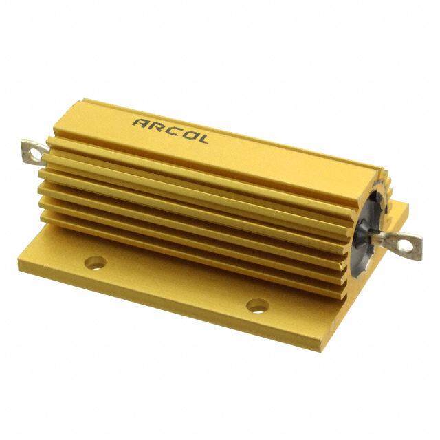
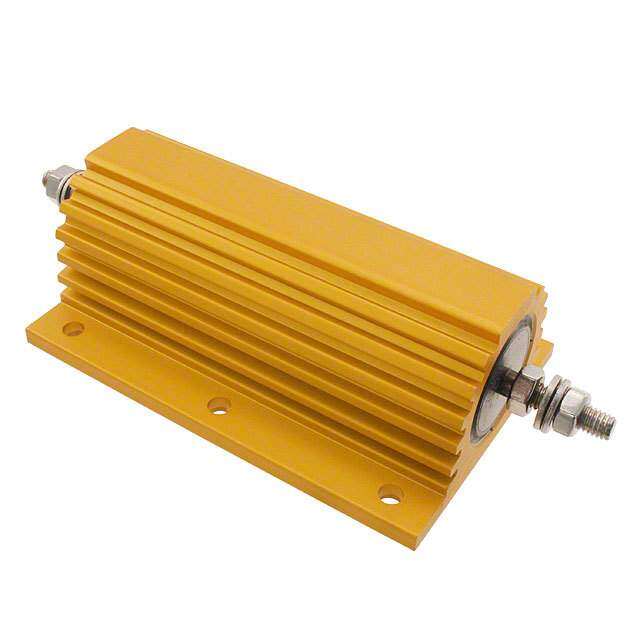
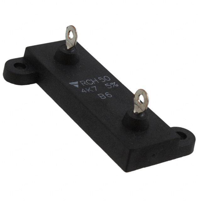
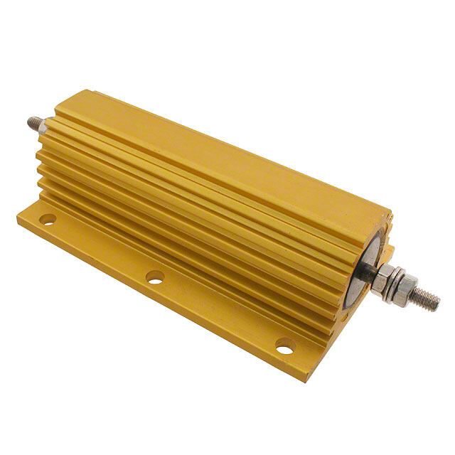
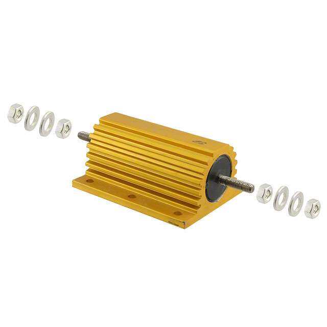
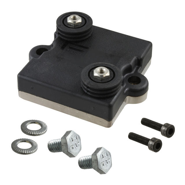
ICGOO电子元器件商城为您提供FSOT4009E5R000KE由Vishay Huntington Electric Inc.设计生产,在icgoo商城现货销售,并且可以通过原厂、代理商等渠道进行代购。 FSOT4009E5R000KE价格参考。Vishay Huntington Electric Inc.FSOT4009E5R000KE封装/规格:底座安装电阻器, 5 Ohms ±10% 40W Wirewound Chassis Mount Resistor。您可以下载FSOT4009E5R000KE参考资料、Datasheet数据手册功能说明书,资料中有FSOT4009E5R000KE 详细功能的应用电路图电压和使用方法及教程。
型号为FSOT4009E5R000KE的电阻器由品牌Vishay Huntington Electric Inc.生产,属于底座安装电阻器的一种。该型号属于绕线电阻器系列,具有较高的功率承受能力和良好的稳定性,常用于需要高可靠性和高耐久性的工业应用中。

该电阻器的典型应用场景包括:

1. 工业控制设备:如PLC(可编程逻辑控制器)、工业自动化系统中的电源管理模块,用于限流、分压或作为负载电阻。

2. 电源系统:用于开关电源、UPS(不间断电源)系统中,作为启动电阻、放电电阻或电流检测电阻。

3. 电机控制电路:在电机驱动器或变频器中用于电流采样或制动电阻电路中,提供稳定的电阻值以确保电机运行的稳定性。

4. 测试与测量设备:用于电子负载、电源测试仪等设备中,作为高精度的负载电阻使用。

5. 交通运输设备:如轨道交通中的牵引控制系统、电动车的电池管理系统(BMS)中,用于电流检测与保护电路。

该电阻器具备良好的温度稳定性和耐久性,适用于对可靠性要求较高的恶劣环境。
| 参数 | 数值 |
| 产品目录 | |
| 描述 | RES CHAS MNT 5 OHM 10% 40W |
| 产品分类 | |
| 品牌 | Vishay Huntington Electric Inc. |
| 数据手册 | |
| 产品图片 |
|
| 产品型号 | FSOT4009E5R000KE |
| rohs | 无铅 / 符合限制有害物质指令(RoHS)规范要求 |
| 产品系列 | FSOT |
| 产品目录绘图 |
|
| 产品目录页面 | |
| 其它名称 | FSOT40-5 |
| 功率(W) | 40W |
| 包装 | 散装 |
| 大小/尺寸 | 2.000" 长 x 1.187" 宽 (50.80mm x 30.16mm) |
| 安装特性 | 法兰支架,直角 |
| 容差 | ±10% |
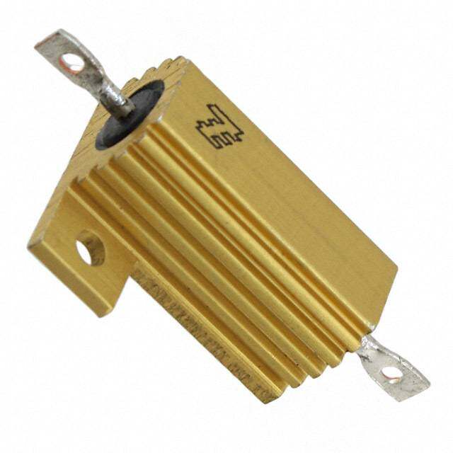
| 封装/外壳 | 径向,扁椭圆形 |
| 引线形式 | 焊片 |
| 成分 | 绕线 |
| 标准包装 | 5 |
| 涂层,外壳类型 | 硅酮涂层 |
| 温度系数 | ±400ppm/°C |
| 特性 | - |
| 电阻(Ω) | 5 |
| 高度 | 0.594" (15.08mm) |


PDF Datasheet 数据手册内容提取
FSOT…XX Flat www.vishay.com Vishay Huntington Wirewound Resistors, Industrial Power, Flat FEATURES • High temperature silicon coating • Mounting accommodations ideally suited to high density packaging • Self-stacking hardware for horizontal or vertical placement • Withstands high vibrations without loosening • Mounting hardware functions as a heat sink allowing greater heat dissipation and less derating of stacked units • Material categorization: for definitions of compliance please see www.vishay.com/doc?99912 STANDARD ELECTRICAL SPECIFICATIONS POWER RATING RESISTANCE RESISTANCE WEIGHT GLOBAL HISTORICAL P RANGE RANGE (typical) MODEL MODEL 25 °C W ± 5 % ± 10 % g FSOT30…14 / FSOT30…16 HL-24-09 / HL-24-16 1.0 to 11K 0.10 to 11K 30 20.14 FSOT30…15 / FSOT30…17 NHL-24-09 / NHL-24-16 1.0 to 1.2K 1.0 to 1.2K FSOT40…14 / FSOT40…16 HL-40-09 / HL-40-16 1.0 to 26K 0.10 to 26K 40 30.07 FSOT40…15 / FSOT40…17 NHL-40-09 / NHL-40-16 1.0 to 3K 1.0 to 3K FSOT55…14 / FSOT55…16 HL-55-09 / HL-55-16 1.0 to 54K 0.10 to 54K 55 51.25 FSOT55…15 / FSOT55…17 NHL-55-09 / NHL-55-16 1.0 to 6.8K 1.0 to 6.8K FSOT70…14 / FSOT70…16 HL-70-09 / HL-70-16 1.0 to 77K 0.10 to 77K 70 60.48 FSOT70…15 / FSOT70…17 NHL-70-09 / NHL-70-16 1.0 to 9.4K 1.0 to 9.4K FSOT95…14 / FSOT95…16 HL-95-09 / HL-95-16 1.0 to 99.9K 0.10 to 99.9K 95 76.51 FSOT95…15 / FSOT95…17 NHL-95-09 / NHL-95-16 1.0 to12.4K 1.0 to 12.4K TECHNICAL SPECIFICATIONS PARAMETER UNIT FSOT…XX FLAT RESISTOR CHARACTERISTICS Temperature Coefficient ppm/°C ± 90 for 0.1 to 0.99 ; ± 50 for 1 to 9.9 ; ± 30 for 10 and above Dielectric Withstanding Voltage V 1000, from terminal to mounting hardware AC Short Time Overload - 10 x rated power for 5 s Maximum Working Voltage V (P x R)1/2 Insulation Resistance 1000 M minimum dry, 100 M minimum after moisture test Operating Temperature Range °C -55 to +350 GLOBAL PART NUMBER INFORMATION Global Part Numbering example: FSOT3009E10R00JE14 F S O T 3 0 0 9 E 1 0 R 0 0 J E 1 4 GLOBAL TERMINAL TERMINAL RESISTANCE TOLERANCE PACKAGING CODE SPECIAL MODEL DESIGNATION FINISH VALUE FSOT30 09 E = lead R = decimal J = ± 5.0 % E = lead (Pb)-free cell and (dash number) (see “Standard 16 (Pb)-free K = thousand K = ± 10.0 % bulk pack (up to 2 digits) Electrical 10R00 = 10.0 from 1 to 99 Specifications” 1K000 = 1 k as applicable 14 = standard, table above for 09 terminal additional P/N’s) 15 = non-inductive, 09 terminal 16 = standard, 16 terminal 17 = non-inductive, 16 terminal Revision: 20-Sep-16 1 Document Number: 30337 For technical questions, contact: ww2dresistors@vishay.com THIS DOCUMENT IS SUBJECT TO CHANGE WITHOUT NOTICE. THE PRODUCTS DESCRIBED HEREIN AND THIS DOCUMENT ARE SUBJECT TO SPECIFIC DISCLAIMERS, SET FORTH AT www.vishay.com/doc?91000
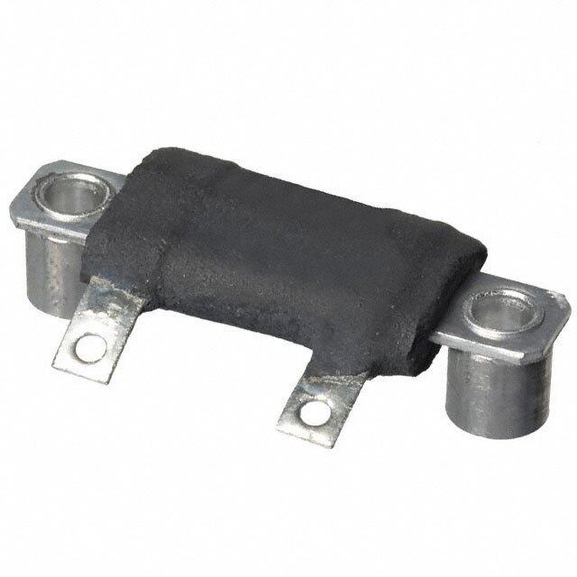
FSOT…XX Flat www.vishay.com Vishay Huntington DIMENSIONS in inches [millimeters] TERMINAL DIMENSIONS TYPE FSOT…XX FLAT STYLE A D A D 0.625 [15.88] C C 1.188 [30.16] 0.594 [15.08] Style 09 B Style 16 B max. DIMENSIONS in inches [millimeters] A 0.196 [4.98] Dia. typ. DIMENSION STYLE 09 STYLE 16 B 0.188 0.188 0.563 ± 0.030 A 0.438 ± 0.030 [4.76] [4.76] [14.29 ± 0.794] [11.11 ± 0.794] 0.500 0.563 C B 0.313 [7.94] Dia. [12.70] [14.29] 0.104 0.050 DIMENSIONS in inches [millimeters] C [2.64] [1.27] DISTANCE TERMINAL MODEL ± 0A.063 ± 0B.063 ± 0C.031 TBEERTMWINEAELNS DESIGNATION D 0[0..05210] 0[0..05210] [1.59] [1.59] [0.79] (ref.) STANDARD OPTIONAL 1.250 2.500 2.000 0.718 TERMINAL FINISH FSOT30 09E 16E [31.75] [63.50] [50.80] [18.24] “E” Finish - 100 % Sn coated steel. 2.000 3.250 2.750 1.468 FSOT40 09E 16E [50.80] [82.55] [69.85] [37.29] NON-INDUCTIVE FSOT55 3.500 4.750 4.250 2.968 09E 16E Models of equivalent physical and electrical specifications [88.90] [120.65] [107.95] [75.39] are available with non-inductive (Aryton-Perry) winding. For 4.750 6.000 5.500 4.218 non-inductive models, maximum resistance values are FSOT70 09E 16E [120.65] [152.40] [139.70] [107.14] lower, see STANDARD ELECTRICAL SPECIFICATIONS 6.000 7.250 6.750 5.468 table. FSOT95 09E 16E [152.40] [184.15] [171.45] [138.89] DERATING POWER RATING Vm25iso4hu.a0ny tmi nFmgS Ohxo T1r i.z0fol2an tm tarmellys] issttotoe re1 l0 wp"a latxtt ae1g i0en" 2rxa5 t i°0nC.g0 sa4 m"a br[e2ie 5nb4ta. 0ws emitdhm no onx % N I R E W 112000 aEirX fCloLwU. SIVE BRACKET DESIGN ET A R O P D 8600 Mounting strap fits snugly through resistor core and is bound against unit by two eccentric spacers. The bracket 40 eliminates expensive cements and improves heat transfer and power handling capabilities. 20 MATERIAL SPECIFICATIONS 0 - 65- 50 0 50 150 250 350 Element: copper-nickel alloy of nickel-chrome alloy, 25 depending on resistance value AMBIENT TEMPERATURE IN ° C Core: ceramic, steatite Derating is required for ambient temperatures above 25 °C Coating: special high temperature silicone per the above graph. Standard Terminals: model “E” terminals are tinned steel Terminal Bands: steel Part Marking: HEI, model, wattage, value, tolerance, date code PERFORMANCE TEST CONDITIONS OF TEST TEST LIMITS Thermal Shock Rated power applied until thermally stable,then a minimum of 15 min at -55 °C ± (2.0 % + 0.05 ) R Short Time Overload 10x rated power for 5 s ± (2.0 % + 0.05 ) R Dielectric Withstanding Voltage 1000 VRMS, 1 min ± (0.1 % + 0.05 ) R Low Temperature Storage -55 °C for 24 h ± (2.0 % + 0.05 ) R High Temperature Exposure 250 h at + 350 °C ± (2.0 % + 0.05 ) R Moisture Resistance MIL-STD-202 Method 106, 7b not applicable ± (2.0 % + 0.05 ) R Shock, Specified Pulse MIL-STD-202 Method 213, 100 g's for 6 ms, 10 shocks ± (0.2 % + 0.05) R Vibration, High Frequency Frequency varied 10 Hz to 2000 Hz, 20 g peak, 2 directions 6 h each ± (0.2 % + 0.05 ) R Load Life 1000 h at rated power, + 25 °C, 1.5 h “ON”, 0.5 h “OFF” ± (3.0 % + 0.05 ) R Revision: 20-Sep-16 2 Document Number: 30337 For technical questions, contact: ww2dresistors@vishay.com THIS DOCUMENT IS SUBJECT TO CHANGE WITHOUT NOTICE. THE PRODUCTS DESCRIBED HEREIN AND THIS DOCUMENT ARE SUBJECT TO SPECIFIC DISCLAIMERS, SET FORTH AT www.vishay.com/doc?91000
Legal Disclaimer Notice www.vishay.com Vishay Disclaimer ALL PRODUCT, PRODUCT SPECIFICATIONS AND DATA ARE SUBJECT TO CHANGE WITHOUT NOTICE TO IMPROV E RELIABILITY, FUNCTION OR DESIGN OR OTHERWISE. Vishay Intertechnology, Inc., its affiliates, agents, and employees, and all persons acting on its or their behalf (collectively, “Vishay”), disclaim any and all liability for any errors, inaccuracies or incompleteness contained in any datasheet or in any other disclosure relating to any product. Vishay makes no warranty, representation or guarantee regarding the suitability of the products for any particular purpose o r the continuing production of any product. To the maximum extent permitted by applicable law, Vishay disclaims (i) any and all liability arising out of the application or use of any product, (ii) any and all liability, including without limitation special, consequential or incidental damages, and (iii) any and all implied warranties, including warranties of fitness for particular purpose, non-infringement and merchantability. Statements regarding the suitability of products for certain types of applications are based on Vishay’s knowledge of typical requirements that are often placed on Vishay products in generic applications. Such statements are not binding statements about the suitability of products for a particular application. It is the customer’s responsibility to validate that a particular product with the properties described in the product specification is suitable for use in a particular application. Parameters provided in datasheets and / or specifications may vary in different applications and performance may vary over time. All operating parameters, including typical parameters, must be validated for each customer application by the customer’s technical experts. Product specifications do not expand or otherwise modify Vishay’s terms and conditions of purchase, including but not limited to the warranty expressed therein. Except as expressly indicated in writing, Vishay products are not designed for use in medical, life-saving, or life-sustainin g applications or for any other application in which the failure of the Vishay product could result in personal injury or death. Customers using or selling Vishay products not expressly indicated for use in such applications do so at their own risk . Please contact authorized Vishay personnel to obtain written terms and conditions regarding products designed for such applications. No license, express or implied, by estoppel or otherwise, to any intellectual property rights is granted by this documen t or by any conduct of Vishay. Product names and markings noted herein may be trademarks of their respective owners. © 2019 VISHAY INTERTECHNOLOGY, INC. ALL RIGHTS RESERVED Revision: 01-Jan-2019 1 Document Number: 91000