ICGOO在线商城 > 电感器,线圈,扼流圈 > 固定值电感器 > FP1007R6-R33-R

 Datasheet下载
- 型号: FP1007R6-R33-R
- 制造商: Bussmann/Cooper
- 库位|库存: xxxx|xxxx
- 要求:
| 数量阶梯 | 香港交货 | 国内含税 |
| +xxxx | $xxxx | ¥xxxx |
查看当月历史价格
查看今年历史价格
FP1007R6-R33-R产品简介:
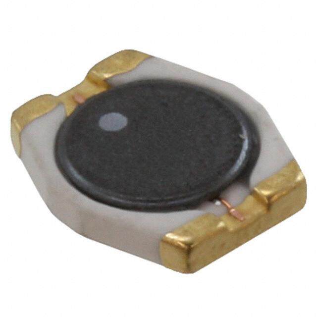
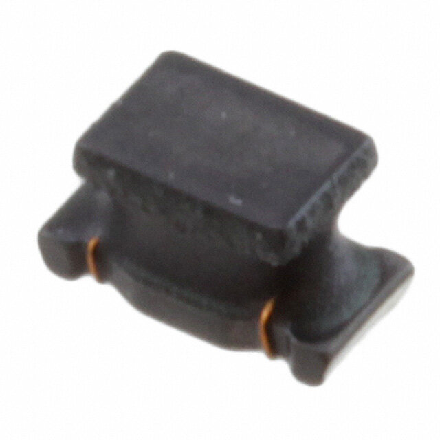
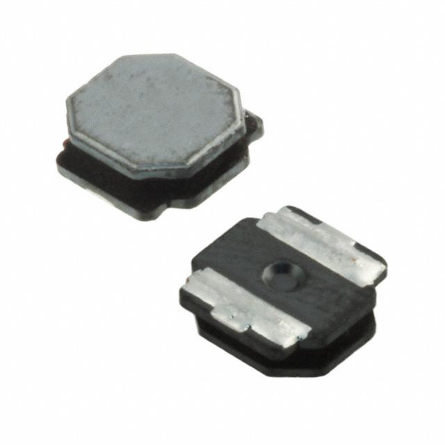
ICGOO电子元器件商城为您提供FP1007R6-R33-R由Bussmann/Cooper设计生产,在icgoo商城现货销售,并且可以通过原厂、代理商等渠道进行代购。 FP1007R6-R33-R价格参考¥5.77-¥7.62。Bussmann/CooperFP1007R6-R33-R封装/规格:固定值电感器, 330nH 无屏蔽 绕线 电感器 61A 0.29 毫欧 非标准 。您可以下载FP1007R6-R33-R参考资料、Datasheet数据手册功能说明书,资料中有FP1007R6-R33-R 详细功能的应用电路图电压和使用方法及教程。
Eaton - Electronics Division 的型号 FP1007R6-R33-R 是一款固定值电感器,其应用场景主要集中在电力电子设备和电路设计领域。以下是该型号电感器的主要应用场景:

1. 电源滤波:
   该电感器可用于直流-直流(DC-DC)转换器、开关电源(SMPS)以及线性电源中的滤波电路。通过与电容器配合,它可以有效抑制高频噪声,提高电源输出的稳定性。

2. 电磁干扰(EMI)抑制:
   在电子设备中,FP1007R6-R 可用于减少电磁干扰。例如,在信号传输线路或电源输入/输出端口上使用该电感器,可以衰减高频干扰信号,确保系统符合EMC(电磁兼容性)标准。

3. 储能与能量转换:
   在开关模式电源(如升压、降压或逆变电路)中,该电感器可以用作储能元件。当电路切换时,它能够存储和释放能量,从而实现电压或电流的调节。

4. 射频(RF)电路应用:
   在射频前端电路中,该电感器可作为匹配网络的一部分,用于调整阻抗以优化信号传输效率。此外,它还可以用作谐振电路中的关键元件。

5. 电机驱动电路:
   在电机驱动器中,FP1007R6-R 可用于平滑电流波动,减少纹波并保护驱动电路免受瞬态电流冲击的影响。

6. 工业自动化设备:
   该电感器适用于工业控制领域的各种设备,如可编程逻辑控制器(PLC)、变频器和伺服驱动器等,用于稳定电源和信号处理。

7. 汽车电子系统:
   在汽车电子应用中,这款电感器可用于车载充电器、LED照明驱动电路以及信息娱乐系统的电源管理部分,提供可靠的性能表现。

总结来说,FP1007R6-R-R33 型号的固定值电感器因其高精度、低损耗和良好的温度稳定性,适合应用于需要高效能和高可靠性的场景,特别是在电源管理、信号处理和电磁兼容性设计中发挥重要作用。
| 参数 | 数值 |
| 产品目录 | |
| DC电阻(DCR) | 0.29 毫欧 |
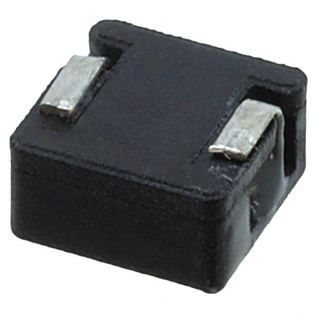
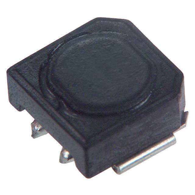
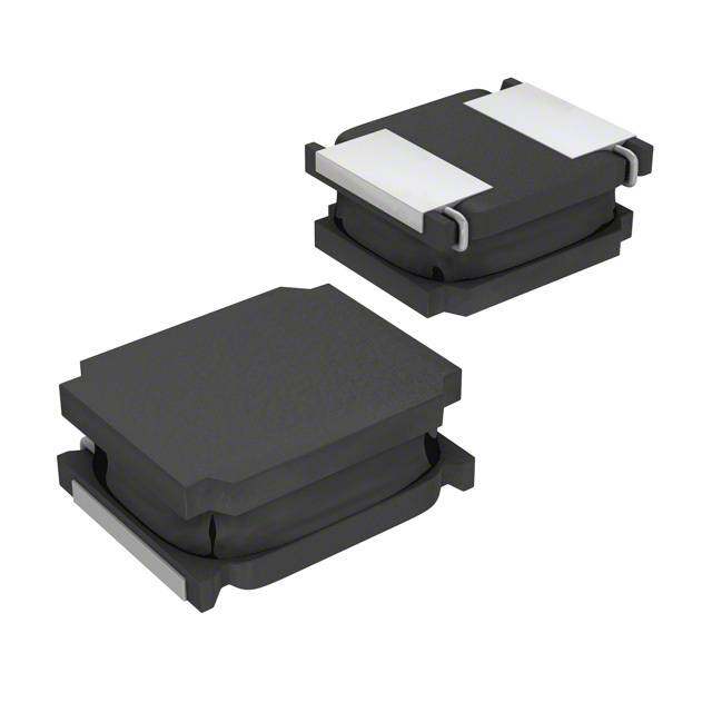
| 描述 | INDUCTOR LO PROFLE 330NH 33A SMD |
| 产品分类 | |
| 品牌 | Eaton Bussmann |
| 数据手册 | |
| 产品图片 |
|
| 产品型号 | FP1007R6-R33-R |
| PCN组件/产地 | |
| rohs | 无铅 / 符合限制有害物质指令(RoHS)规范要求 |
| 产品系列 | FLAT-PAC, FP1007R6 |
| 不同频率时的Q值 | - |
| 供应商器件封装 | - |
| 其它名称 | 283-4179-1 |
| 包装 | 剪切带 (CT) |
| 大小/尺寸 | 0.413" 长 x 0.315" 宽 (10.50mm x 8.00mm) |
| 安装类型 | 表面贴装 |
| 容差 | ±10% |
| 封装/外壳 | 非标准 |
| 屏蔽 | 无屏蔽 |
| 工作温度 | -40°C ~ 125°C |
| 材料-磁芯 | 铁氧体 |
| 标准包装 | 1 |
| 特色产品 | http://www.digikey.cn/product-highlights/cn/zh/cooper-bussmann-high-current-inductors/2979 |
| 电感 | 330nH |
| 电流-饱和值 | 33A |
| 类型 | 绕线 |
| 频率-测试 | 100kHz |
| 频率-自谐振 | - |
| 额定电流 | 61A |
| 高度-安装(最大值) | 0.276"(7.00mm) |


- 商务部:美国ITC正式对集成电路等产品启动337调查
- 曝三星4nm工艺存在良率问题 高通将骁龙8 Gen1或转产台积电
- 太阳诱电将投资9.5亿元在常州建新厂生产MLCC 预计2023年完工
- 英特尔发布欧洲新工厂建设计划 深化IDM 2.0 战略
- 台积电先进制程称霸业界 有大客户加持明年业绩稳了
- 达到5530亿美元!SIA预计今年全球半导体销售额将创下新高
- 英特尔拟将自动驾驶子公司Mobileye上市 估值或超500亿美元
- 三星加码芯片和SET,合并消费电子和移动部门,撤换高东真等 CEO
- 三星电子宣布重大人事变动 还合并消费电子和移动部门
- 海关总署:前11个月进口集成电路产品价值2.52万亿元 增长14.8%


PDF Datasheet 数据手册内容提取
Effective June 2017 Technical Data 10007 Supersedes September 2012 FP1007R6 High frequency, high current power inductors Applications • Multi-phase regulators • Voltage Regulator Modules (VRMs) • Desktop and server VRMs and EVRDs • Data networking and storage systems • Graphics cards and battery power systems • Point-of-Load modules • DCR Sensing Environmental data SMD Device • Storage temperature range (component): -40 °C to +125 °C Product features • Operating temperature range: -40 °C to +125 °C • 10.5 x 8.0 x 7.0mm Maximum surface mount (ambient plus self-temperature rise) package • Solder reflow temperature: • Ferrite core material J-STD-020 (latest revision) compliant • Controlled DCR tolerance for sensing circuits • Inductance Range from 150nH to 470nH Pb HHALOFGEN • Current range from 23.5 to 75 Amps FREE • Frequency range up to 2MHz • Halogen free, lead free, RoHS compliant
Technical Data 10007 FP1007R6 Effective June 2017 High frequency, high current power inductors Product Specifications Part OCL1 ±10% FLL2Min. Irms3 Isat14 @25°C Isat25 @100°C DCR @20°C Number7 (nH) (nH) (Amps) (Amps) (Amps) (mΩ) K-Factor 6 FP1007R6-R15-R 150 108 75.0 60.0 FP1007R6-R18-R 180 129 60.0 50.0 FP1007R6-R22-R 220 158 50.0 40.0 FP1007R6-R27-R 270 194 61 41.0 33.0 0.29 ± 5% 348.8 FP1007R6-R33-R 330 237 33.0 26.5 FP1007R6-R39-R 390 280 28.0 22.5 FP1007R6-R47-R 470 338 23.5 19.0 1.Open Circuit Inductance (OCL) Test Parameters: 100kHz, 0.10Vrms, 0.0Adc 5.Isat2: Peak current for approximately 20% rolloff at +100°C. 2.Full Load Inductance (FLL) Test Parameters: 100kHz, 0.1Vrms, Isat1 6.K-factor: Used to determine Bp-p for core loss (see graph). Bp-p = K * L 3.Irms: DC current for an approximate temperature rise of 40°C without core loss. Derating is * ∆I * 10-3. Bp-p:(Gauss), K: (K-factor from table), L: (Inductance in nH), necessary for AC currents. PCB layout, trace thickness and width, air-flow, and proximity of ∆I (peak-to-peak ripple current in Amps). other heat generating components will affect the temperature rise. It is recommended that 7.Part Number Definition: FP1007R6-Rxx-R the temperature of the part not exceed 125°C under worst case operating conditions FP1007R6 = Product code and size verified in the end application. Rxx= Inductance value in uH, R = decimal point 4.Isat1: Peak current for approximately 20% rolloff at +25°C. -R suffix = RoHS compliant Dimensions- mm The nominal DCR is measured from point "A" to point "B" Part Marking: 1007R6, Rxx = Inductance value in µH. (R = Decimal point) wwllyy = Date code R = Revision level Tolerance are ±0.15mm unless otherwise specified. Soldering surfaces to be coplanar within 0.1016mm. PCB tolerance ±0.1mm unless otherwise specified. Packaging information - mm 1.5 dia 2.0 1.75 1.5 dia 4.0 A 11.5 1 24.0 ±0.30 10.60 2 8.1 Supplied in Tape-and-Reel packaging, 700 parts per 13 inch diameter reel. 12.0 A 7.1 SECTION A-A 2 www.eaton.com/electronics
FP1007R6 Technical Data 10007 High frequency, high current power inductor Effective June 2017 Temperature rise vs total loss 60 50 C) e (° 40 s Ri ure 30 at er p m 20 e T 10 0 0.0 0.4 0.8 1.2 1.6 2.0 Total Loss (W) Core loss vs Bp-p 1MHz 500kHz 10 300kHz 200kHz 1 100kHz W) 0.1 s ( s o L e 0.01 or C 0.001 0.0001 0.00001 100 1000 10000 Bp-p (Gauss) Inductance characteristics % of OCL vs. I 1 sat 100% 80% 60% L C O of % 40% -40°C +100°C +25°C 20% 0% 0% 20% 40% 60% 80% 100% 120% 140% 160% % of Isat1 www.eaton.com/electronics 3
Technical Data 10007 FP1007R6 Effective June 2017 High frequency, high current power inductor Solder Reflow Profile TP TTaabbllee 11 -- SSttaannddaarrdd SSnnPPbb SSoollddeerr ((TTcc)) TC -5°C Max. Ramp Up Rate = 3°C/s tP Volume Volume Max. Ramp Down Rate = 6°C/s Package mm3 mm3 Thickness <350 >_350 TL <2.5mm 235°C 220°C Preheat t A >_2.5mm 220°C 220°C e Tsmax atur TTaabbllee 22 -- LLeeaadd ((PPbb)) FFrreeee SSoollddeerr ((TTcc)) per Volume Volume Volume Tem Tsmin ts Package mm3 mm3 mm3 Thickness <350 350 - 2000 >2000 <1.6mm 260°C 260°C 260°C 1.6 – 2.5mm 260°C 250°C 245°C >2.5mm 250°C 245°C 245°C 25°C Time 25°C to Peak Time Reference JDEC J-STD-020 Profile Feature Standard SnPb Solder Lead (Pb) Free Solder Preheat and Soak (cid:129)Temperature min.(Tsmin) 100°C 150°C (cid:129)Temperature max.(Tsmax) 150°C 200°C (cid:129)Time (Tsminto Tsmax) (ts) 60-120 Seconds 60-120 Seconds Average ramp up rate Tsmaxto Tp 3°C/ Second Max. 3°C/ Second Max. Liquidous temperature (TL) 183°C 217°C Time at liquidous (tL) 60-150 Seconds 60-150 Seconds Peak package body temperature (TP)* Table 1 Table 2 Time (tp)** within 5 °C of the specified classification temperature (Tc) 20 Seconds** 30 Seconds** Average ramp-down rate (Tpto Tsmax) 6°C/ Second Max. 6°C/ Second Max. Time 25°C to Peak Temperature 6 Minutes Max. 8 Minutes Max. *Tolerance for peak profile temperature (Tp) is defined as a supplier minimum and a user maximum. ** Tolerance for time at peak profile temperature (tp) is defined as a supplier minimum and a user maximum. Life Support Policy: Eaton does not authorize the use of any of its products for use in life support devices or systems without the express written approval of an officer of the Company. Life support systems are devices which support or sustain life, and whose failure to perform, when properly used in accordance with instructions for use provided in the labeling, can be reasonably expected to result in significant injury to the user. Eaton reserves the right, without notice, to change design or construction of any products and to discontinue or limit distribution of any products. Eaton also reserves the right to change or update, without notice, any technical information contained in this bulletin. Eaton Electronics Division 1000 Eaton Boulevard Cleveland, OH 44122 United States www.eaton.com/electronics © 2017 Eaton All Rights Reserved Eaton is a registered trademark. Printed in USA Publication No. 10007 BU-SB12795 All other trademarks are property June 2017 of their respective owners.