ICGOO在线商城 > 连接器,互连器件 > FFC,FPC(扁平柔性)连接器 > FH52-15S-0.5SH(99)
.jpg)
 Datasheet下载
- 型号: FH52-15S-0.5SH(99)
- 制造商: Hirose Electric
- 库位|库存: xxxx|xxxx
- 要求:
| 数量阶梯 | 香港交货 | 国内含税 |
| +xxxx | $xxxx | ¥xxxx |
查看当月历史价格
查看今年历史价格
FH52-15S-0.5SH(99)产品简介:
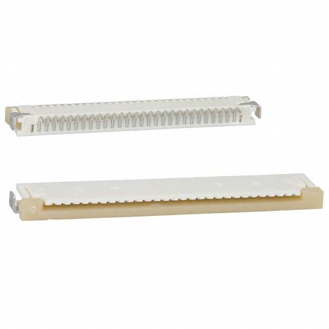
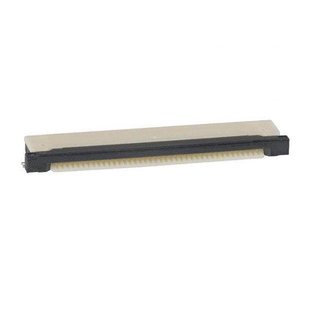
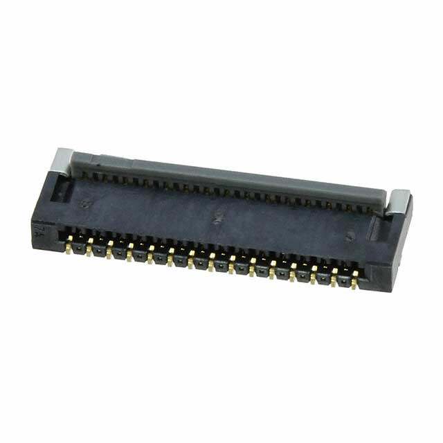
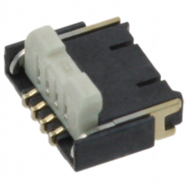
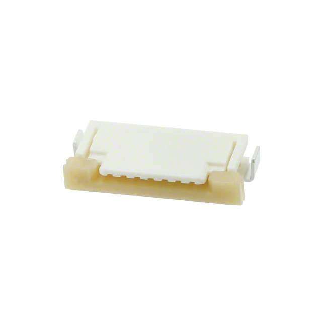
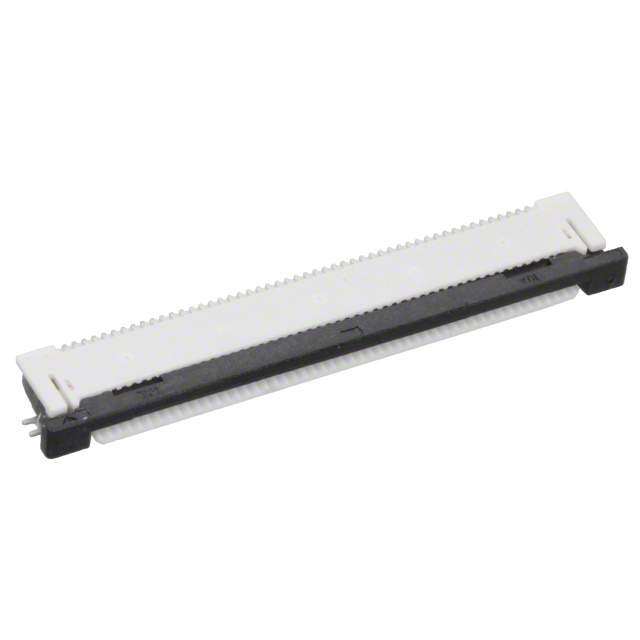
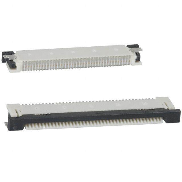
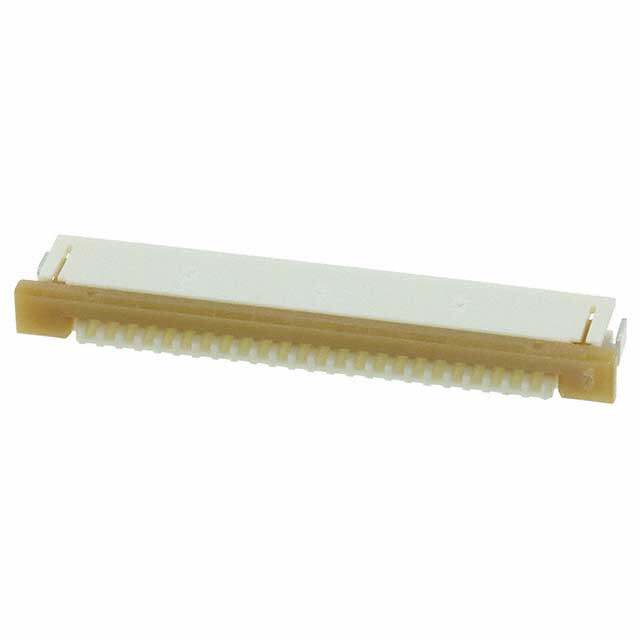
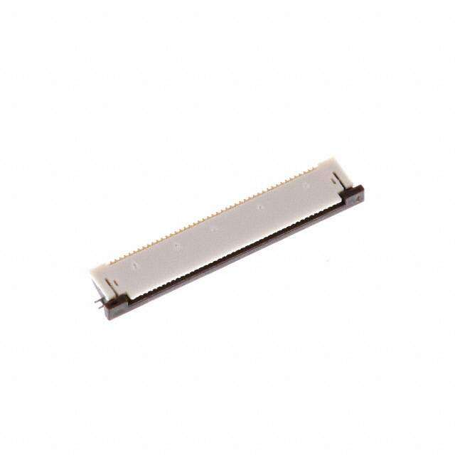
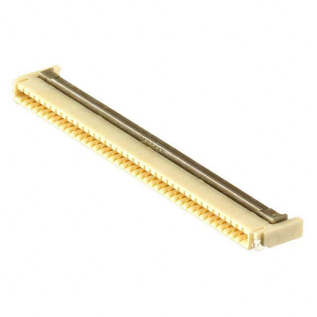
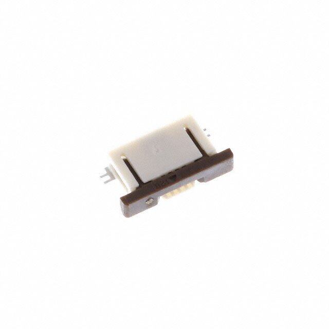
ICGOO电子元器件商城为您提供FH52-15S-0.5SH(99)由Hirose Electric设计生产,在icgoo商城现货销售,并且可以通过原厂、代理商等渠道进行代购。 FH52-15S-0.5SH(99)价格参考。Hirose ElectricFH52-15S-0.5SH(99)封装/规格:FFC,FPC(扁平柔性)连接器, 15 Position FFC, FPC Connector Contacts, Bottom 0.020" (0.50mm) Surface Mount, Right Angle。您可以下载FH52-15S-0.5SH(99)参考资料、Datasheet数据手册功能说明书,资料中有FH52-15S-0.5SH(99) 详细功能的应用电路图电压和使用方法及教程。
Hirose Electric Co Ltd的FH52-15S-0.5SH(99)是一款FFC/FPC(扁平柔性)连接器,广泛应用于需要高密度、小间距和可靠信号传输的电子设备中。该型号具有0.5mm超细间距和15位引脚设计,适用于空间受限的紧凑型设备。其主要应用场景包括便携式消费类电子产品,如智能手机、平板电脑、数码相机和可穿戴设备(如智能手表和健康监测设备),用于连接显示屏、摄像头模组与主板之间的信号传输。

此外,该连接器也常见于工业控制设备、医疗电子设备(如便携式监护仪)、小型打印机及家用电器的液晶面板模块中,因其具备良好的插拔耐久性、稳定的电气性能和抗振动能力。FH52系列采用表面贴装(SMT)方式,适合自动化生产,提升组装效率。其结构设计支持盲插导向,便于装配并减少误插风险。整体而言,FH52-15S-0.5SH(99)适用于对空间、可靠性和高频信号传输有较高要求的中高端电子产品。
| 参数 | 数值 |
| 产品目录 | |
| 描述 | CONN FPC/FFC 15POS .5MM SMD R/AFFC & FPC连接器 15P 0.5MM PITCH R/A SMT, AU |
| 产品分类 | |
| FFC,FCB厚度 | 0.30mm |
| 品牌 | Hirose Electric Co Ltd |
| 产品手册 | |
| 产品图片 |
|
| rohs | 符合RoHS无铅 / 符合限制有害物质指令(RoHS)规范要求 |
| 产品系列 | FFC & FPC连接器,Hirose Connector FH52-15S-0.5SH(99)FH52 |
| 数据手册 | |
| 产品型号 | FH52-15S-0.5SH(99) |
| 产品种类 | FFC & FPC连接器 |
| 产品类型 | Board Mount |
| 位置数量 | 15 |
| 其它名称 | FH5215S05SH99 |
| 包装 | 带卷 (TR) |
| 商标 | Hirose Connector |
| 外壳材料 | 液晶聚合物(LCP), 不含卤素的 |
| 安装类型 | 表面贴装,直角 |
| 安装角 | Right |
| 封装 | Reel |
| 工作温度 | -40°C ~ 85°C |
| 工厂包装数量 | 500 |
| 扁平柔性类型 | FFC, FPC |
| 材料可燃性等级 | UL94 V-0 |
| 板上高度 | 0.079"(2.00mm) |
| 标准包装 | 500 |
| 特性 | - |
| 电缆端类型 | 焊片式 |
| 端接 | |
| 端接类型 | SMD |
| 系列 | FH52 |
| 联系位置 | Bottom Contact |
| 致动器材料 | 液晶聚合物(LCP), 不含卤素的 |
| 节距 | 0.5 mm |
| 触头材料 | 磷青铜 |
| 触头镀层 | 金 |
| 连接器/触头类型 | 触点, 底部 |
| 针脚数 | 15 |
| 锁定功能 | 触发锁 |
| 间距 | 0.020"(0.50mm) |
| 额定电压 | - |
| 额定电流 | 0.5A |

.JPG)


.jpg)

- 商务部:美国ITC正式对集成电路等产品启动337调查
- 曝三星4nm工艺存在良率问题 高通将骁龙8 Gen1或转产台积电
- 太阳诱电将投资9.5亿元在常州建新厂生产MLCC 预计2023年完工
- 英特尔发布欧洲新工厂建设计划 深化IDM 2.0 战略
- 台积电先进制程称霸业界 有大客户加持明年业绩稳了
- 达到5530亿美元!SIA预计今年全球半导体销售额将创下新高
- 英特尔拟将自动驾驶子公司Mobileye上市 估值或超500亿美元
- 三星加码芯片和SET,合并消费电子和移动部门,撤换高东真等 CEO
- 三星电子宣布重大人事变动 还合并消费电子和移动部门
- 海关总署:前11个月进口集成电路产品价值2.52万亿元 增长14.8%
.jpg)
PDF Datasheet 数据手册内容提取
0.5mm and 1mm Pitch, 2mm Height, FPC/FFC ZIF Connectors FH52 Series Secure actuator retention Metal fittings are designed to hold and stabilize the actuator d. e v r e s e R s ht g Ri Contacts are designed to hold and All stabilize the actuator D. T ■Features L Extended metal fitting option (FH52E/FH52K/FH52T) O., 1. Highly reliable connection and robust structure C With the need for higher contact counts and the need for C a connector body that delivers unquestionable strength RI and a reliable connection in a FPC/FFC connector, the T C FH52 series has made great strides to meet this need. It E meets this need with the following: L E -An FPC positioning mechanism that delivers the high E reliability requested S -A reliable and secure connection that is packed into a O well-designed, durable structure. R HI 2. Product variations capable of meeting a range of needs 8 ・FH52E : Long metal fittings type 1 0 Easy visual inspection of solder posts after processing. ht 2 ・ F 1 2H55℃2 hKe a: tL roesnisgt amnte ctaonl nfiettcintogrs m teyeptes ,s 1e2ve5r℃e a Huteomato Rtivees riesqtauniret mTyenptes Tenhaeb mlee ata vl ifsitutianlg ins sepxetectniodn o ouft iftrso smo ltdheer icnogn cnoencdtoitrio bnosd.y to g ri ・FH52T : Long metal fittings type, 2-Point Contact Type y op C ontact structure with independent springs connects with 22--PPooiinnttss ooff CCoonnttaacctt ((FFHH5522TT)) C FPC/FCC at 2 points reducing failure from dust intrusion. 8 3. Simplified operations 1 0 The flip lock structure makes it easier to engage/ 2 disengage the actuator and reduces the required force 1. c. needed to operate. A clear tactile click is delivered upon e the successful completion of the mating process. D 4. Increased retention force The side catch technology combined with tabbed FPC/FFC increase the horizontal retention force of the FPC/FFC. 5. Accepts standard 0.3mm thick FPC/FFC It accepts 0.3mm thick products that are easy to manufacture and have superb insertion performance. 2-point contact structure with independent springs to 6. Fully molded structure aids PCB layout improve reliability. The bottom of this connector is enclosed by a fully molded structure that protects the contacts and removes SSiiddee ccaattcchh tteecchhnnoollooggyy ddeessiiggnneedd ttoo ppllaaccee aa tteemmppoorraarryy any restrictions from PCB patterning and design. hhoolldd oonn tthhee FFPPCC//FFFFCC bbeeffoorree tthhee lloocckk iiss eennggaaggeedd.. 7. Halogen-free All materials and substances used to produce this product comply with Halogen-free standards.* As defined in IEC 61249-2-21. Br : 900 ppm or less, Cl : 900 ppm or less, Br+Cl : 1,500 ppm or less 8. Supports automatic pick-n-place mounting Offered in tape and reel packaging that is compatible with automatic machine mounting. (3,000pcs/reel) 9. Multiple packing options The standard packaging is 3,000pcs/reel, but it is also FPC/FFC with tab increase the offered in a 500pcs/reel. (The outer diameter of the reel will be Ø180mm in this case.) retention force in horizontal direction. Ipnl ecaassee sc ownhtaecret ath ceo ampppalincya trieopnr ewsielln dteamtivaen fdo ar fhuirgthh eler vineflo orfm raetliiaobni.lity, such as automotive, 2017.8r 1
FH52 Series●0.5mm and 1mm Pitch, 2mm Height, FPC/FFC ZIF Connectors ■Product Specifications Operating temperature range : -40ç to +105°C (Note 2)(Note 4) Storage temperature range : -10ç to +50°C (Note 3) Rated current 0.5A (Note 1) Rating Operating humidity range : Relative humidity 90% max. Storage humidity range : Relative humidity 90% max. Rated voltage 50V AC rms (No condensation) (No condensation) Adaptive FPC/FFC Thickness: = 0.3 ± 0.05mm Gold plated contact traces contact specifications Item Specification Conditions 1. Insulation resistance 500Mø min. 100V DC 2. Withstanding voltage No flashover or insulation breakdown 150V AC rms / 1 minute 3. Contact 50mø max. 1mA (DC or 1000Hz) resistance * Including FPC/FFC conductor resistance d. erve 4. ( Dinsuerrtaionb /i lwitityhdrawal) CNoon dtaacmt aregsei,s ctarancckes :, 5o0r mpaør tms adxis.location 20 cycles s e R No electrical discontinuity of 1µs or more hts 5. Vibration Contact resistance : 50mø max. F10re cqyucelensc yin : e1a0c tho o5f5 tHhze, 3s idnigrelec taiomnpslitude of 0.75mm, g No damage, cracks, or parts dislocation Ri All No electrical discontinuity of 1µs or more Acceleration of 981m/s2, duration of 6 ms, sine half-wave D. 6. Shock Contact resistance : 50mø max. waveform, 3 cycles in each of the 3 axes T No damage, cracks, or parts dislocation L O., 7. Humidity Contact resistance : 50mø max. 96 hours at temperature of 40ç and humidity of 90% to C Insulation resistance : 50Mø min. (Steady state) 95% C No damage, cracks, or parts dislocation RI T Contact resistance : 50mø max. Temperature : -40°C / +15ç to +35ç / +105ç(Note 4) / +15ç to +35ç C 8. Temperature E Insulation resistance : 50Mø min. Time : 30 / 2 to 3 / 30 / 2 to 3 (Minutes) cycle L No damage, cracks, or parts dislocation 5 cycles E E S 9. Resistance to No deformation of components affecting Reflow : Peak temperature 250°C max., 230°C or more, 30 seconds or less O soldering heat performance Manual soldering: 350 ± 10°C for 5 seconds R HI Note 1 : When passing the current through all of the contacts, use 70% of the current rating. 8 Note 2 : Includes temperature rise caused by current flow. 1 0 Note 3 : The term “storage” refers to products stored for long period of time prior to mounting and use. Operating Temperature Range 2 ht and Humidity Range covers non-conducting condition of installed connectors in storage, shipment or during transportation. g Note 4 : FH52K withstands up to +125°C. ri y p o C ■Materials / Finish 8 1 0 Part Material Finish Remarks 2 1. Color : Grey c. Insulator LCP UL94V-0 e Color : Black D Contacts Copper alloy Partially gold plated –––––– Metal fittings Brass Tine plated ■Product Number Structure Refer to the chart below when datermining the product specifications from the product number. Please select from the product numbers listed in this catalog when placing orders. FH 52 E − 50 (25) S B − 0.5 SH (99) ❶ w e r t y u i o !0 q Series name : FH y Contact arrangement : Single (pole piece array) w Series No. : 52 u Alternating direction : e Blank : Standard type No symbol : Standard type (all contacts loaded) E : Long metal fittings type A : Alternating contact type (Alternating on the polarity side) K : Long metal fittings type, +125°C Heat Resistant type B : Alternating contact type (Alternating on the opposite polarity side) T : Long metal fittings type, 2-Point Contact type i Contact pitch : 0.5mm, 1mm r Standard type : Number of contacts o Termination type Alternating contact type : Mold size SH : SMT horizontal mounting type t Standard type : No symbol !00 SpecificationBlank : Partially gold plated, 3,000pcs/reel Alternating contact type : Number of contacts (99) : Partially gold plated, 500pcs/reel 2
FH52 Series●0.5mm and 1mm Pitch, 2mm Height, FPC/FFC ZIF Connectors ■Connector Dimensions [FH52 (Standard Type) 0.5mm Pitch product] A±0.15 B±0.08 0.5±0.08 (0.12) 5) ( A ** a Number of d. Cav No. contacts indicator e v r e s e (0.15) R (C) s D±0.1 c b ht g Ri a detail drawing D. All 6 c (110˚) 5±0.2 O., LT (3.9) 0.2 1.7 ± C 20 0 C RI 1 2 0.15MAX (1.3) 0.15MAX 1 2 T 1.4±0.1 C Notes 1 The coplanarity of each terminal lead is within 0.1. E 2 The contact terminal lead position indicates the dimension from the b surface, the bottom 3±0.1 0.45±0.1 L (4.3) 0.7±0.2 E surface of the insulator body. E 5.7±0.2 S 3 Packaged on tape and reel only. Check the packaging specification on Page 16 for details. O 4 Sink mark reliefs may be added due to improvements R HI 5 Sight variations in color of the plastic compounds do not affect form, fit or function. 8 After reflow, the terminal plating may change color; however this does not represent a quality issue. 1 6 The dimensions of 60-contact actuators are shown in the figures. 0 2 ht Unit : mm g ri Part No. HRS No. No. of contacts A B C D y op FH52-4S-0.5SH(**) 4 6.3 1.5 2.57 4.7 C Under planning (Note 2) FH52-5S-0.5SH(**) 5 6.8 2.0 3.07 5.2 8 FH52-6S-0.5SH(**) 580-3304-0 ** 6 7.3 2.5 3.57 5.7 1 0 FH52-8S-0.5SH(**) 580-3305-3 ** 8 8.3 3.5 4.57 6.7 2 1. FH52-10S-0.5SH(**) 580-3306-6 ** 10 9.3 4.5 5.57 7.7 ec. FH52-11S-0.5SH(**) 580-3320-7 ** 11 9.8 5.0 6.07 8.2 D FH52-12S-0.5SH(**) 580-3307-9 ** 12 10.3 5.5 6.57 8.7 FH52-15S-0.5SH(**) 580-3302-5 ** 15 11.8 7.0 8.07 10.2 FH52-16S-0.5SH(**) Under planning (Note 2) 16 12.3 7.5 8.57 10.7 FH52-18S-0.5SH(**) 580-3321-0 ** 18 13.3 8.5 9.57 11.7 FH52-20S-0.5SH(**) 580-3309-4 ** 20 14.3 9.5 10.57 12.7 FH52-22S-0.5SH(**) 580-3317-2 ** 22 15.3 10.5 11.57 13.7 FH52-24S-0.5SH(**) 580-3318-5 ** 24 16.3 11.5 12.57 14.7 FH52-25S-0.5SH(**) 580-3316-0 ** 25 16.8 12.0 13.07 15.2 FH52-26S-0.5SH(**) 580-3319-8 ** 26 17.3 12.5 13.57 15.7 FH52-28S-0.5SH(**) 580-3324-8 ** 28 18.3 13.5 14.57 16.7 FH52-30S-0.5SH(**) 580-3310-3 ** 30 19.3 14.5 15.57 17.7 FH52-32S-0.5SH(**) 580-3325-0 ** 32 20.3 15.5 16.57 18.7 FH52-40S-0.5SH(**) 580-3300-0 ** 40 24.3 19.5 20.57 22.7 FH52-42S-0.5SH(**) 580-3329-1 ** 42 25.3 20.5 21.57 23.7 FH52-45S-0.5SH(**) 580-3311-6 ** 45 26.8 22.0 23.07 25.2 FH52-50S-0.5SH(**) 580-3303-8 ** 50 29.3 24.5 25.57 27.7 FH52-60S-0.5SH(**) 580-3301-2 ** 60 34.3 29.5 30.57 32.7 Note 1 : Tape and reel packaging. (3,000pcs/reel, 500pcs/reel) Order by number of reels. Note 2 : Contact positions without HRS No. are currently under planning. Please contact hirose for detailed information about product variation. 3
FH52 Series●0.5mm and 1mm Pitch, 2mm Height, FPC/FFC ZIF Connectors ■Connector Dimensions [FH52 (Standard Type) 1mm Pitch product] A±0.15 (Q) B±0.08 (R) 1±0.08 (0.12) 5) ( A ** d. e v Cav No. a r e s c e R s ht g Ri (0.15) All (C) b D. D±0.1 a detail drawing T L C CO., 6 c 2±0.2 (110˚) 5±0.2 RI 1.7 T 9) C 3. E ( L 0 0 E E S 1 2 0.15MAX (1.3) 0.15MAX 1 2 O 0.45±0.1 R 1.4±0.1 HI 8 3±0.1 0.7±0.2 1 (4.3) 0 2 ht Notes 1 The coplanarity of each terminal lead is within 0.1. 5.7±0.2 g 2 The contact terminal lead position indicates the dimension from the b surface, ri y the bottom surface of the insulator body. p o 3 Packaged on tape and reel only. Check the packaging specification on Page 16 for details. C 8 4 Sink mark reliefs may be added due to improvements 1 5 Sight variations in color of the plastic compounds do not affect form, fit or function. 0 2 After reflow, the terminal plating may change color; however this does not represent a quality issue. 1. c. 6 The dimensions of 30-contact actuators are shown in the figures. e D Unit : mm Part No. HRS No. No. of contacts A B C D Q R FH52-10(4)SA-1SH(**) 580-3330-0 ** 4 9.3 3 5.57 7.7 2.9 3.4 FH52-12S-1SH(**) 580-3323-5 ** 12 16.8 11 13.07 15.2 2.9 2.9 FH52-32(16)SB-1SH(**) 580-3338-2 ** 16 20.3 15 16.57 18.7 2.4 2.9 FH52-60(30)SB-1SH(**) 580-3315-7 ** 30 34.3 29 30.57 32.7 2.4 2.9 Note 1 : Tape and reel packaging. (3,000pcs/reel, 500pcs/reel) Order by number of reels. 4
FH52 Series●0.5mm and 1mm Pitch, 2mm Height, FPC/FFC ZIF Connectors ■Connector Dimensions [FH52E (Long Metal Fittings Type) 0.5mm Pitch product] A±0.15 B±0.08 0.5±0.08 (0.12) 5) ( A ** a Number of d. Cav No. contacts indicator e v r e s e R (C) c hts D±0.1 b g E±0.2 a detail drawing Ri D. All 6 c ) (110˚) 0.275± T 9 1. O., L 3.(0.2± C 20 0 C 1.2±0.2(1.3) RI 1 2 0.15MAX 0.15MAX 1 2 T C Notes 1 The coplanarity of each terminal lead is within 0.1. 1.55±0.2 0.45±0.1 LE 2 The contact terminal lead position indicates the dimension from the b surface, (4.3) 0.7±0.2 E the bottom surface of the insulator body. 5.7±0.2 E S 3 Packaged on tape and reel only. Check the packaging specification on Page 16 for details. O 4 Sink mark reliefs may be added due to improvements R HI 5 Sight variations in color of the plastic compounds do not affect form, fit or function. 8 After reflow, the terminal plating may change color ; however this does not represent a quality issue. 1 6 The dimensions of 60-contact actuators are shown in the figures. 0 2 ht Unit : mm g ri Part No. HRS No. No. of contacts A B C D E y p FH52E-4S-0.5SH(**) 4 6.3 1.5 2.57 4.55 7.1 o C FH52E-5S-0.5SH(**) Under planning (Note 2) 5 6.8 2.0 3.07 5.05 7.6 8 FH52E-6S-0.5SH(**) 6 7.3 2.5 3.57 5.55 8.1 1 0 FH52E-8S-0.5SH(**) 580-3349-0 ** 8 8.3 3.5 4.57 6.55 9.1 2 1. FH52E-10S-0.5SH(**) 580-3346-0 ** 10 9.3 4.5 5.57 7.55 10.1 c. FH52E-11S-0.5SH(**) 11 9.8 5.0 6.07 8.05 10.6 e Under planning (Note 2) D FH52E-12S-0.5SH(**) 12 10.3 5.5 6.57 8.55 11.1 FH52E-15S-0.5SH(**) 580-3337-0 ** 15 11.8 7.0 8.07 10.05 12.6 FH52E-16S-0.5SH(**) Under planning (Note 2) 16 12.3 7.5 8.57 10.55 13.1 FH52E-18S-0.5SH(**) 580-3331-3 ** 18 13.3 8.5 9.57 11.55 14.1 FH52E-20S-0.5SH(**) 580-3357-0 ** 20 14.3 9.5 10.57 12.55 15.1 FH52E-22S-0.5SH(**) 580-3343-2 ** 22 15.3 10.5 11.57 13.55 16.1 FH52E-24S-0.5SH(**) 580-3340-4 ** 24 16.3 11.5 12.57 14.55 17.1 FH52E-25S-0.5SH(**) 25 16.8 12.0 13.07 15.05 17.6 FH52E-26S-0.5SH(**) Under planning (Note 2) 26 17.3 12.5 13.57 15.55 18.1 FH52E-28S-0.5SH(**) 28 18.3 13.5 14.57 16.55 19.1 FH52E-30S-0.5SH(**) 580-3347-3 ** 30 19.3 14.5 15.57 17.55 20.1 FH52E-32S-0.5SH(**) Under planning (Note 2) 32 20.3 15.5 16.57 18.55 21.1 FH52E-40S-0.5SH(**) 580-3334-1 ** 40 24.3 19.5 20.57 22.55 25.1 FH52E-42S-0.5SH(**) 42 25.3 20.5 21.57 23.55 26.1 Under planning (Note 2) FH52E-45S-0.5SH(**) 45 26.8 22.0 23.07 25.05 27.6 FH52E-50S-0.5SH(**) 580-3335-4 ** 50 29.3 24.5 25.57 27.55 30.1 FH52E-60S-0.5SH(**) 580-3339-5 ** 60 34.3 29.5 30.57 32.55 35.1 FH52E-64S-0.5SH(**) 580-3333-9 ** 64 36.3 31.5 32.57 34.55 37.1 FH52E-68S-0.5SH(**) 580-3332-6 ** 68 38.3 33.5 34.57 36.55 39.1 Note 1 : Tape and reel packaging. (3,000pcs/reel, 500pcs/reel) Order by number of reels. Note 2 : Contact positions without HRS No. are currently under planning.Please contact hirose for detailed information about product variation. 5
FH52 Series●0.5mm and 1mm Pitch, 2mm Height, FPC/FFC ZIF Connectors ■Connector Dimensions [FH52E (Long Metal Fittings Type) 1mm Pitch product] A±0.15 (Q) B±0.08 (R) 1±0.08 (0.12) 5) ( AA **** d. e Cav No. a v r e c s e R s ht g Ri All (C) b D. D±0.1 T E±0.2 a detail drawing L CO., 6 c 2±0.2 (110˚) 0.2 C 5± RI 1.7 T 9) C 3. E ( L 0 0 E E S 1 2 0.15MAX (1.3) 0.15MAX 1 2 O R 1.2±0.2 0.45±0.1 HI 1.55±0.2 0.7±0.2 8 1 (4.3) 20 Notes 1 The coplanarity of each terminal lead is within 0.1. ht 2 The contact terminal lead position indicates the dimension from the b surface, 5.7±0.2 rig the bottom surface of the insulator body. y p 3 Packaged on tape and reel only. Check the packaging specification on Page 16 for details. o C 4 Sink mark reliefs may be added due to improvements 8 5 Sight variations in color of the plastic compounds do not affect form, fit or function. 01 After reflow, the terminal plating may change color; however this does not represent a quality issue. 2 1. 6 The dimensions of 30-contact actuators are shown in the figures. c. e Unit : mm D Part No. HRS No. No. of contacts A B C D E Q R FH52E-8(4)SB-1SH(**) 580-3351-0 ** 4 8.3 3 4.57 6.55 9.1 2.4 2.9 FH52E-20(10)SA-1SH(**) 580-3352-0 ** 10 14.3 9 10.57 12.55 15.1 2.9 2.4 FH52E-20(10)SB-1SH(**) 580-3353-0 ** 10 14.3 9 10.57 12.55 15.1 2.4 2.9 FH52E-50(25)SA-1SH(**) 580-3354-0 ** 25 29.3 24 25.57 27.55 30.1 2.9 2.4 FH52E-50(25)SB-1SH(**) 580-3355-0 ** 25 29.3 24 25.57 27.55 30.1 2.4 2.9 FH52E-60(30)SB-1SH(**) 580-3358-0 ** 30 34.3 29 30.57 32.55 35.1 2.4 2.9 Note 1 : Tape and reel packaging. (3,000pcs/reel, 500pcs/reel) Order by number of reels. 6
FH52 Series●0.5mm and 1mm Pitch, 2mm Height, FPC/FFC ZIF Connectors ■Connector Dimensions [FH52K (Long Metal Fittings Type, 125°C Heat Resistant Type) 0.5mm Pitch product] A±0.15 B±0.08 0.5±0.08 (0.12) 5) ( A ** d. Cav No. e v a er Number of contacts indicator s c e R s ht g Ri All (C) b D. D±0.1 T E±0.2 a detail drawing L C CO., 6 c 2±0.2 (110˚) ±0.2 5 RI 1.7 CT 3.9) E ( L 0 0 E E S 1 2 0.15MAX (1.3)0.15MAX 1 2 O R 1.2±0.2 0.45±0.1 HI 1.55±0.2 0.7±0.2 8 1 Notes 1 The coplanarity of each terminal lead is within 0.1. (4.3) 0 2 2 The contact terminal lead position indicates the dimension from the b surface, ht the bottom surface of the insulator body. 5.7±0.2 g ri 3 Packaged on tape and reel only. Check the packaging specification on Page 16 for details. y p 4 Sink mark reliefs may be added due to improvements o C 5 Sight variations in color of the plastic compounds do not affect form, fit or function. 8 After reflow, the terminal plating may change color; however this does not represent a quality issue. 1 0 6 The dimensions of 60-contact actuators are shown in the figures. 2 Unit : mm 1. c. Part No. HRS No. No. of contacts A B C D E e D FH52K-6S-0.5SH(**) 580-4613-0 ** 6 7.3 2.5 3.57 5.55 8.1 FH52K-8S-0.5SH(**) 580-4611-0 ** 8 8.3 3.5 4.57 6.55 9.1 FH52K-10S-0.5SH(**) 580-4606-0 ** 10 9.3 4.5 5.57 7.55 10.1 FH52K-12S-0.5SH(**) 12 10.3 5.5 6.57 8.55 11.1 FH52K-15S-0.5SH(**) Under planning (Note 2) 15 11.8 7.0 8.07 10.05 12.6 FH52K-18S-0.5SH(**) 18 13.3 8.5 9.57 11.55 14.1 FH52K-20S-0.5SH(**) 580-4604-0 ** 20 14.3 9.5 10.57 12.55 15.1 FH52K-22S-0.5SH(**) 22 15.3 10.5 11.57 13.55 16.1 FH52K-24S-0.5SH(**) 24 16.3 11.5 12.57 14.55 17.1 FH52K-25S-0.5SH(**) Under planning (Note 2) 25 16.8 12.0 13.07 15.05 17.6 FH52K-26S-0.5SH(**) 26 17.3 12.5 13.57 15.55 18.1 FH52K-30S-0.5SH(**) 30 19.3 14.5 15.57 17.55 20.1 FH52K-32S-0.5SH(**) 580-4600-9 ** 32 20.3 15.5 16.57 18.55 21.1 FH52K-34S-0.5SH(**) 580-4601-0 ** 34 21.3 16.5 17.57 19.55 22.1 FH52K-40S-0.5SH(**) 40 24.3 19.5 20.57 22.55 25.1 FH52K-50S-0.5SH(**) 50 29.3 24.5 25.57 27.55 30.1 Under planning (Note 2) FH52K-60S-0.5SH(**) 60 34.3 29.5 30.57 32.55 35.1 FH52K-64S-0.5SH(**) 64 36.3 31.5 32.57 34.55 37.1 FH52K-68S-0.5SH(**) 580-4614-0 ** 68 38.3 33.5 34.57 36.55 39.1 Note 1 : Tape and reel packaging. (3,000pcs/reel, 500pcs/reel) Order by number of reels. Note 2 : C ontact positions without HRS No. are currently under planning. Please contact hirose for detailed information about product variation. 7
FH52 Series●0.5mm and 1mm Pitch, 2mm Height, FPC/FFC ZIF Connectors ■Connector Dimensions [FH52T (Long Metal Fittings Type, 2-Point Contact Type) 0.5mm Pitch product] A±0.15 (2.35) B±0.08 (2.45) 0.5±0.08 (0.08) 5) ( A ** Cav No. d. Number of contacts indicator a e v c r e s e R s ht g (C) b Ri D±0.1 All E±0.2 a detail drawing LTD. 6 c 2±0.2 (110˚) ±0.2 O., 1.75 C 9) C (3. RI 0 0 T C (1.2) E 1 2 0.15MAX 0.15MAX 1 2 L (1.6) E 1.2±0.2 0.45±0.1 E S Notes 1 The coplanarity of each terminal lead is within 0.1. 1.55±0.2 0.7±0.2 O 2 The contact terminal lead position indicates the dimension from the b surface, (4.2) R HI the bottom surface of the insulator body. 5.7±0.2 8 3 Packaged on tape and reel only. Check the packaging specification on Page 16 for details. 1 0 4 Sink mark reliefs may be added due to improvements 2 ht 5 Sight variations in color of the plastic compounds do not affect form, fit or function. g After reflow, the terminal plating may change color; however this does not represent a quality issue. ri py 6 The dimensions of 60-contact actuators are shown in the figures. o Unit : mm C 8 Part No. HRS No. No. of contacts A B C D E 1 FH52T-4S-0.5SH(**) 4 6.3 1.5 2.57 4.55 7.1 0 1.2 FFHH5522TT--56SS--00..55SSHH((****)) Under planning (Note 2) 56 67..83 22..05 33..0577 55..0555 78..61 c. FH52T-8S-0.5SH(**) 8 8.3 3.5 4.57 6.55 9.1 e D FH52T-10S-0.5SH(**) 580-4503-0 ** 10 9.3 4.5 5.57 7.55 10.1 FH52T-11S-0.5SH(**) 11 9.8 5.0 6.07 8.05 10.6 FH52T-12S-0.5SH(**) 12 10.3 5.5 6.57 8.55 11.1 FH52T-15S-0.5SH(**) 15 11.8 7.0 8.07 10.05 12.6 FH52T-16S-0.5SH(**) Under planning (Note 2) 16 12.3 7.5 8.57 10.55 13.1 FH52T-18S-0.5SH(**) 18 13.3 8.5 9.57 11.55 14.1 FH52T-20S-0.5SH(**) 20 14.3 9.5 10.57 12.55 15.1 FH52T-22S-0.5SH(**) 22 15.3 10.5 11.57 13.55 16.1 FH52T-24S-0.5SH(**) 580-4500-0 ** 24 16.3 11.5 12.57 14.55 17.1 FH52T-25S-0.5SH(**) 25 16.8 12.0 13.07 15.05 17.6 FH52T-26S-0.5SH(**) 26 17.3 12.5 13.57 15.55 18.1 Under planning (Note 2) FH52T-28S-0.5SH(**) 28 18.3 13.5 14.57 16.55 19.1 FH52T-30S-0.5SH(**) 30 19.3 14.5 15.57 17.55 20.1 FH52T-32S-0.5SH(**) 580-4502-0 ** 32 20.3 15.5 16.57 18.55 21.1 FH52T-40S-0.5SH(**) 40 24.3 19.5 20.57 22.55 25.1 FH52T-42S-0.5SH(**) Under planning (Note 2) 42 25.3 20.5 21.57 23.55 26.1 FH52T-45S-0.5SH(**) 45 26.8 22.0 23.07 25.05 27.6 FH52T-50S-0.5SH(**) 580-4501-7 ** 50 29.3 24.5 25.57 27.55 30.1 FH52T-60S-0.5SH(**) 60 34.3 29.5 30.57 32.55 35.1 FH52T-64S-0.5SH(**) Under planning (Note 2) 64 36.3 31.5 32.57 34.55 37.1 FH52T-68S-0.5SH(**) 68 38.3 33.5 34.57 36.55 39.1 Note 1 : Tape and reel packaging. (3,000pcs/reel, 500pcs/reel) Order by number of reels. Note 2 : C ontact positions without HRS No. are currently under planning. Please contact hirose for detailed information about product variation. 8
FH52 Series●0.5mm and 1mm Pitch, 2mm Height, FPC/FFC ZIF Connectors BRecommended PCB Mounting Pattern and Metal Mask Dimensions [FH52 (Standard Type) 0.5mm Pitch product] Recommended metal mask thickness : 0.12mm 5 B±0.05 0 0. ± 5 8 0. Connector image 0.3±0.03(Land pattern) 5 0.5±0.05 0 0.25±0.03(Metal mask) 0. ± 6 4. 05 0. ± 2 d. e v r e s e R E±0.05 0.8±0.03 s ht * The recommended PCB mounting pattern for the FH12 Series (horizontal g Ri mounting type) can be used as well. All BRecommended FPC/FFC Dimensions D. [FH52 (Standard Type) 0.5mm Pitch product] T L O., 1 F±0.1 C G±0.05 C 0.5±0.07 B±0.03 0.5±0.07 RI T 2-R0.2±0.05 0.5±0.03 0.35±0.03(FPC) C 0.3±0.03(FFC) 0.3±0.05 E 2-R0.2±0.1 1 L E E 2-R0.2±0.1 1 8 HIROS 3.5MIN 13.1±0.1 11.35±0.1 (1MIN) 4.5MIN 01 2-R0.2±0.1 1 2 ht 2-R0.2±0.05 1 g ri y p Notes 1 FFC/FPC without tabs can also be used. o C In that case, the specified portions are not necessary. 8 Unit : mm 01 Part No. HRS No. No. of contacts B E F G 2 1. FH52-4S-0.5SH(**) Under planning (Note 1) 4 1.5 4.1 4.1 2.5 c. FH52-5S-0.5SH(**) 5 2.0 4.6 4.6 3.0 e D FH52-6S-0.5SH(**) 580-3304-0 ** 6 2.5 5.1 5.1 3.5 FH52-8S-0.5SH(**) 580-3305-3 ** 8 3.5 6.1 6.1 4.5 FH52-10S-0.5SH(**) 580-3306-6 ** 10 4.5 7.1 7.1 5.5 FH52-11S-0.5SH(**) 580-3320-7 ** 11 5.0 7.6 7.6 6.0 FH52-12S-0.5SH(**) 580-3307-9 ** 12 5.5 8.1 8.1 6.5 FH52-15S-0.5SH(**) 580-3302-5 ** 15 7.0 9.6 9.6 8.0 FH52-16S-0.5SH(**) Under planning (Note 1) 16 7.5 10.1 10.1 8.5 FH52-18S-0.5SH(**) 580-3321-0 ** 18 8.5 11.1 11.1 9.5 FH52-20S-0.5SH(**) 580-3309-4 ** 20 9.5 12.1 12.1 10.5 FH52-22S-0.5SH(**) 580-3317-2 ** 22 10.5 13.1 13.1 11.5 FH52-24S-0.5SH(**) 580-3318-5 ** 24 11.5 14.1 14.1 12.5 FH52-25S-0.5SH(**) 580-3316-0 ** 25 12.0 14.6 14.6 13.0 FH52-26S-0.5SH(**) 580-3319-8 ** 26 12.5 15.1 15.1 13.5 FH52-28S-0.5SH(**) 580-3324-8 ** 28 13.5 16.1 16.1 14.5 FH52-30S-0.5SH(**) 580-3310-3 ** 30 14.5 17.1 17.1 15.5 FH52-32S-0.5SH(**) 580-3325-0 ** 32 15.5 18.1 18.1 16.5 FH52-40S-0.5SH(**) 580-3300-0 ** 40 19.5 22.1 22.1 20.5 FH52-42S-0.5SH(**) 580-3329-1 ** 42 20.5 23.1 23.1 21.5 FH52-45S-0.5SH(**) 580-3311-6 ** 45 22.0 24.6 24.6 23.0 FH52-50S-0.5SH(**) 580-3303-8 ** 50 24.5 27.1 27.1 25.5 FH52-60S-0.5SH(**) 580-3301-2 ** 60 29.5 32.1 32.1 30.5 Note 1 : C ontact positions without HRS No. are currently under planning. Please contact hirose for detailed information about product variation. 9
FH52 Series●0.5mm and 1mm Pitch, 2mm Height, FPC/FFC ZIF Connectors BRecommended PCB Mounting Pattern and Metal Mask Dimensions [FH52 (Standard Type) 1mm Pitch product] Recommended metal mask thickness : 0.12mm 5 0 ±0. B±0.05 5 0.8 1±0.05 0.3±0.03(Land pattern) 0.25±0.03(Metal mask) 5 0 0. ± 6 4. d. e v r (Connector image) e s 5 Re 0.0 S±0.05 T±0.05 ± s 2 E±0.05 0.8±0.03 ht g Ri All D. BRecommended FPC/FFC Dimensions T L O., [FH52 (Standard Type) 1mm Pitch product] C C 1 F±0.1 RI G±0.07 T C U±0.1 B±0.05 V±0.1 E L 0.3±0.05 E 1±0.05 0.6±0.03 E 2-R0.2±0.05 S O 2-R0.2±0.1 1 R HI 2-R0.2±0.1 1 ht 2018 3.5MIN (1MIN) 4.5MIN g ri y Cop ±0.1 ±0.1 2-R0.2±0.1 1 8 3.1 1.35 2-R0.2±0.05 1 1 0 1 2 1 1. c. Notes 1 FFC/FPC without tabs can also be used. e D In that case, the specified portions are not necessary. Unit : mm Part No. HRS No. No. of contacts B E F G S T U V FH52-10(4)SA-1SH(**) 580-3330-0 ** 4 3 7.1 7.1 5.5 1.8 2.3 1.5 1 FH52-12S-1SH(**) 580-3323-5 ** 12 11 14.6 14.6 13.0 1.8 1.8 1 1 FH52-32(16)SB-1SH(**) 580-3338-2 ** 16 15 18.1 18.1 16.5 1.3 1.8 1 0.5 FH52-60(30)SB-1SH(**) 580-3315-7 ** 30 29 32.1 32.1 30.5 1.3 1.8 1 0.5 10
FH52 Series●0.5mm and 1mm Pitch, 2mm Height, FPC/FFC ZIF Connectors BRecommended PCB Mounting Pattern and Metal Mask Dimensions [FH52E (Long Metal Fittings Type) 0.5mm Pitch product] Recommended metal mask thickness : 0.12mm 5 0 0. B±0.05 Connector image ± 0.85 (0.2) (0.2) 0.5±0.05 0.3±0.03(Land pattern) 5 0.25±0.03(Metal mask) 0 0. ± 5 8 5. 5 0 d. ±0. e 1.8 v eser (0.3) (0.3)(0.225) R (0.5) s F±0.05 2±0.03 ght BRecommended FPC/FFC Dimensions Ri All [FH52E (Long Metal Fittings Type) 0.5mm Pitch product] D. 1 G±0.1 T L H±0.05 O., 0.5±0.07 B±0.03 0.5±0.07 C 0.3±0.05 C 2-R0.2±0.05 0.5±0.03 0.35±0.03(FPC) RI 0.3±0.03(FFC) T 2-R0.2±0.1 1 C E 2-R0.2±0.1 1 L ROSE E 3.5MIN 1MIN() 4.5MIN HI 18 0.1 0.1± 2-R0.2±0.1 1 0 ± 5 2-R0.2±0.05 1 2 1 3 ht 3. 1. g ri 1 1 y p Notes 1 FFC/FPC without tabs can also be used. o C In that case, the specified portions are not necessary. 8 Unit : mm 01 Part No. HRS No. No. of contacts B F G H 2 FH52E-4S-0.5SH(**) 4 1.5 4.1 4.1 2.5 1. c. FH52E-5S-0.5SH(**) Under planning (Note 1) 5 2.0 4.6 4.6 3.0 e FH52E-6S-0.5SH(**) 6 2.5 5.1 5.1 3.5 D FH52E-8S-0.5SH(**) 580-3349-0 ** 8 3.5 6.1 6.1 4.5 FH52E-10S-0.5SH(**) 580-3346-0 ** 10 4.5 7.1 7.1 5.5 FH52E-11S-0.5SH(**) 11 5.0 7.6 7.6 6.0 Under planning (Note 1) FH52E-12S-0.5SH(**) 12 5.5 8.1 8.1 6.5 FH52E-15S-0.5SH(**) 580-3337-0 ** 15 7.0 9.6 9.6 8.0 FH52E-16S-0.5SH(**) Under planning (Note 1) 16 7.5 10.1 10.1 8.5 FH52E-18S-0.5SH(**) 580-3331-3 ** 18 8.5 11.1 11.1 9.5 FH52E-20S-0.5SH(**) 580-3357-0 ** 20 9.5 12.1 12.1 10.5 FH52E-22S-0.5SH(**) 580-3343-2 ** 22 10.5 13.1 13.1 11.5 FH52E-24S-0.5SH(**) 580-3340-4 ** 24 11.5 14.1 14.1 12.5 FH52E-25S-0.5SH(**) 25 12.0 14.6 14.6 13.0 FH52E-26S-0.5SH(**) Under planning (Note 1) 26 12.5 15.1 15.1 13.5 FH52E-28S-0.5SH(**) 28 13.5 16.1 16.1 14.5 FH52E-30S-0.5SH(**) 580-3347-3 ** 30 14.5 17.1 17.1 15.5 FH52E-32S-0.5SH(**) Under planning (Note 1) 32 15.5 18.1 18.1 16.5 FH52E-40S-0.5SH(**) 580-3334-1 ** 40 19.5 22.1 22.1 20.5 FH52E-42S-0.5SH(**) 42 20.5 23.1 23.1 21.5 Under planning (Note 1) FH52E-45S-0.5SH(**) 45 22.0 24.6 24.6 23.0 FH52E-50S-0.5SH(**) 580-3335-4 ** 50 24.5 27.1 27.1 25.5 FH52E-60S-0.5SH(**) 580-3339-5 ** 60 29.5 32.1 32.1 30.5 FH52E-64S-0.5SH(**) 580-3333-9 ** 64 31.5 34.1 34.1 32.5 FH52E-68S-0.5SH(**) 580-3332-6 ** 68 33.5 36.1 36.1 34.5 Note 1 : C ontact positions without HRS No. are currently under planning. Please contact hirose for detailed information about product variation. 11
FH52 Series●0.5mm and 1mm Pitch, 2mm Height, FPC/FFC ZIF Connectors BRecommended PCB Mounting Pattern and Metal Mask Dimensions [FH52E (Long Metal Fittings Type) 1mm Pitch product] Recommended metal mask thickness : 0.12mm 5 0.0 B±0.05 ± 5 0.8 1±0.05 0.3±0.03(Land pattern) 0.25±0.03(Metal mask) 5 0 0. ± 5 5.8 (Connector image) d. e v r e s e R s S±0.05 T±0.05 ht 05 Rig 8±0. F±0.05 2±0.03 All 1. D. BRecommended FPC/FFC Dimensions T L O., [FH52E (Long Metal Fittings Type) 1mm Pitch product] C C 1 G±0.1 RI H±0.07 T C E U±0.1 B±0.05 V±0.1 L E E 2-R0.2±0.05 1±0.05 0.6±0.03 0.3±0.05 S O R 2-R0.2±0.1 1 HI ht 2018 3.5MIN 2-R0.2±0.1 1 (1MIN) 4.5MIN g ri y 1 2-R0.2±0.1 1 op ±0. 0.1 C 1 ± 2-R0.2±0.05 1 8 3. 1.35 1 1 0 2 1 1. c. Notes 1 FFC/FPC without tabs can also be used. e D In that case, the specified portions are not necessary. Unit : mm Part No. HRS No. No. of contacts B F G H S T U V FH52E-8(4)SB-1SH(**) 580-3351-0 ** 4 3 6.1 6.1 4.5 1.3 1.8 1 0.5 FH52E-20(10)SA-1SH(**) 580-3352-0 ** 10 9 12.1 12.1 10.5 1.8 1.3 0.5 1 FH52E-20(10)SB-1SH(**) 580-3353-0 ** 10 9 12.1 12.1 10.5 1.3 1.8 1 0.5 FH52E-50(25)SA-1SH(**) 580-3354-0 ** 25 24 27.1 27.1 25.5 1.8 1.3 0.5 1 FH52E-50(25)SB-1SH(**) 580-3355-0 ** 25 24 27.1 27.1 25.5 1.3 1.8 1 0.5 FH52E-60(30)SB-1SH(**) 580-3358-0 ** 30 34.3 32.1 32.1 30.5 1.3 1.8 1 0.5 12
FH52 Series●0.5mm and 1mm Pitch, 2mm Height, FPC/FFC ZIF Connectors BRecommended PCB Mounting Pattern and Metal Mask Dimensions [FH52K (Long Metal Fittings Type, 125°C Heat Resistant Type) 0.5mm Pitch product] Recommended metal mask thickness : 0.12mm 5 0 0. B±0.05 Connector image ± 0.85 (0.2) (0.2) 0.5±0.05 0.3±0.03(Land pattern) 5 0.25±0.03(Metal mask) 0 0. ± 5 8 5. 5 ed. ±0.0 v 8 r 1. e s 3) 3) Re (0. (0.(0.225) s (0.5) ht F±0.05 2±0.03 g Ri All BRecommended FPC/FFC Dimensions D. [FH52K (Long Metal Fittings Type, 125°C Heat Resistant Type) 0.5mm Pitch product] T L O., 1 G±0.1 C C H±0.05 0.3±0.05 RI 0.5±0.07 B±0.03 0.5±0.07 CT 2-R0.2±0.05 0.5±0.03 0.35±0.03(FPC) E 0.3±0.03(FFC) 2-R0.2±0.1 1 L E 2-R0.2±0.1 1 E HIROS 3.5MIN 1MIN() 4.5MIN 8 1 ht 20 0.1± 50.1± 22--RR00..22±±00..105 11 rig 3.1 1.3 y p o 1 1 C 8 Notes 1 FFC/FPC without tabs can also be used. 01 In that case, the specified portions are not necessary. 2 c.1. Unit : mm e D Part No. HRS No. No. of contacts B F G H FH52K-6S-0.5SH(**) 580-4613-0 ** 6 2.5 5.1 5.1 3.5 FH52K-8S-0.5SH(**) 580-4611-0 ** 8 3.5 6.1 6.1 4.5 FH52K-10S-0.5SH(**) 580-4606-0 ** 10 4.5 7.1 7.1 5.5 FH52K-12S-0.5SH(**) 12 5.5 8.1 8.1 6.5 FH52K-15S-0.5SH(**) Under planning (Note 1) 15 7.0 9.6 9.6 8.0 FH52K-18S-0.5SH(**) 18 8.5 11.1 11.1 9.5 FH52K-20S-0.5SH(**) 580-4604-0 ** 20 9.5 12.1 12.1 10.5 FH52K-22S-0.5SH(**) 22 10.5 13.1 13.1 11.5 FH52K-24S-0.5SH(**) 24 11.5 14.1 14.1 12.5 FH52K-25S-0.5SH(**) Under planning (Note 1) 25 12.0 14.6 14.6 13.0 FH52K-26S-0.5SH(**) 26 12.5 15.1 15.1 13.5 FH52K-30S-0.5SH(**) 30 14.5 17.1 17.1 15.5 FH52K-32S-0.5SH(**) 580-4600-9 ** 32 15.5 18.1 18.1 16.5 FH52K-34S-0.5SH(**) 580-4601-0 ** 34 16.5 19.1 19.1 17.5 FH52K-40S-0.5SH(**) 40 19.5 22.1 22.1 20.5 FH52K-50S-0.5SH(**) 50 24.5 27.1 27.1 25.5 Under planning (Note 1) FH52K-60S-0.5SH(**) 60 29.5 32.1 32.1 30.5 FH52K-64S-0.5SH(**) 64 31.5 34.1 34.1 32.5 FH52K-68S-0.5SH(**) 580-4614-0 ** 68 33.5 36.1 36.1 34.5 Note 1 : C ontact positions without HRS No. are currently under planning. Please contact hirose for detailed information about product variation. 13
FH52 Series●0.5mm and 1mm Pitch, 2mm Height, FPC/FFC ZIF Connectors BRecommended PCB Mounting Pattern and Metal Mask Dimensions [FH52T (Long Metal Fittings Type, 2-Point Contact Type) 0.5mm Pitch product] Recommended metal mask thickness : 0.12mm 05 B±0.05 0. ± 5 0.5±0.05 0.3±0.03(Land pattern) 8 0. 0.25±0.03(Metal mask) 5 0 0. ± 5 d. 5.8 (Connector image) e v r e s e R s ght 0.05 F±0.05 2±0.03 Ri 8± All BRecomm1.ended FPC/FFC Dimensions D. T [FH52T (Long Metal Fittings Type, 2-Point Contact Type) 0.5mm Pitch product] L O., 1 G±0.1 C C H±0.05 0.3±0.05 RI 0.5±0.07 B±0.03 0.5±0.07 T 2-R0.2±0.05 0.5±0.03 0.35±0.03(FPC) EC 0.3±0.03(FFC) 2-R0.2±0.1 1 L E 2-R0.2±0.1 1 E N S MI ) N RO 3.5 MIN 5MI HI 1( 4. 8 201 0.1 0.1± 2-R0.2±0.1 1 ht 1± 35 2-R0.2±0.05 1 rig 3. 1. y p 1 1 o C 8 Notes 1 FFC/FPC without tabs can also be used. 1 In that case, the specified portions are not necessary. 0 Unit : mm 2 1. Part No. HRS No. No. of contacts B F G H c. FH52T-4S-0.5SH(**) 4 1.5 4.1 4.1 2.5 e D FH52T-5S-0.5SH(**) 5 2.0 4.6 4.6 3.0 Under planning (Note 1) FH52T-6S-0.5SH(**) 6 2.5 5.1 5.1 3.5 FH52T-8S-0.5SH(**) 8 3.5 6.1 6.1 4.5 FH52T-10S-0.5SH(**) 580-4503-0 ** 10 4.5 7.1 7.1 5.5 FH52T-11S-0.5SH(**) 11 5.0 7.6 7.6 6.0 FH52T-12S-0.5SH(**) 12 5.5 8.1 8.1 6.5 FH52T-15S-0.5SH(**) 15 7.0 9.6 9.6 8.0 FH52T-16S-0.5SH(**) Under planning (Note 1) 16 7.5 10.1 10.1 8.5 FH52T-18S-0.5SH(**) 18 8.5 11.1 11.1 9.5 FH52T-20S-0.5SH(**) 20 9.5 12.1 12.1 10.5 FH52T-22S-0.5SH(**) 22 10.5 13.1 13.1 11.5 FH52T-24S-0.5SH(**) 580-4500-0 ** 24 11.5 14.1 14.1 12.5 FH52T-25S-0.5SH(**) 25 12.0 14.6 14.6 13.0 FH52T-26S-0.5SH(**) 26 12.5 15.1 15.1 13.5 Under planning (Note 1) FH52T-28S-0.5SH(**) 28 13.5 16.1 16.1 14.5 FH52T-30S-0.5SH(**) 30 14.5 17.1 17.1 15.5 FH52T-32S-0.5SH(**) 580-4502-0 ** 32 15.5 18.1 18.1 16.5 FH52T-40S-0.5SH(**) 40 19.5 22.1 22.1 20.5 FH52T-42S-0.5SH(**) Under planning (Note 1) 42 20.5 23.1 23.1 21.5 FH52T-45S-0.5SH(**) 45 22.0 24.6 24.6 23.0 FH52T-50S-0.5SH(**) 580-4501-7 ** 50 24.5 27.1 27.1 25.5 FH52T-60S-0.5SH(**) 60 29.5 32.1 32.1 30.5 FH52T-64S-0.5SH(**) Under planning (Note 1) 64 31.5 34.1 34.1 32.5 FH52T-68S-0.5SH(**) 68 33.5 36.1 36.1 34.5 Note 1 : C ontact positions without HRS No. are currently under planning. Please contact hirose for detailed information about product variation. 14
FH52 Series●0.5mm and 1mm Pitch, 2mm Height, FPC/FFC ZIF Connectors BFH52 Series FPC/FFC Construction (Recommended Specifications) 1. Using Single-Sided FPC FPC : Flexible Printed Circuit Material name Material Thickness (µm) Covering film layer Polyimide 1mil (25) Cover adhesive (25) Surface treatment 0.2 µm thick gold plated over 1 to 5 µm thick nickel underplating 3 Copper foil Cu 1oz 35 Base adhesive Thermosetting adhesive 25 Base film Polyimide 1mil thick 25 d. Reinforcement material adhesive Thermosetting adhesive 30 e v Stiffener Polyimide 7mil thick 175 r e s Total 293 e R s ht 2. Using Double-Sided FPC FPC : Flexible Printed Circuit g Ri All Material name Material Thickness (µm) D. Covering film layer Polyimide 1mil (25) T Cover adhesive (25) L O., Surface treatment 0.2 µm thick gold plated over 1 to 5 µm thick nickel underplating 3 C Through-hole copper Cu 15 C RI Copper foil Cu 1/2oz 18 T C Base adhesive Thermosetting adhesive 18 E L Base film Polyimide 1mil thick 25 E E Base adhesive Thermosetting adhesive 18 S O Copper foil Cu 1/2oz (18) R Cover adhesive Thermosetting adhesive 25 HI 8 Covering layer film Polyimide 1mil thick 25 1 0 Reinforcement material adhesive Thermosetting adhesive 50 2 ht Stiffener Polyimide 4mil thick 100 g yri * To prevent release of the FPC due to its bending, use of the double sided Total 297 p o FPC with copper foil on the back side is not recommended. C 8 1 20 3. Using FFC FFC : Flexible Flat Cable 1. ec. Material name Material Thickness (µm) D Polyester film (12) Adhesive Thermoplastic polyester (30) Gold plated annealed copper foil 35 Adhesive Polyester 30 Polyester 12 Adhesive Polyester 30 Stiffener Polyester 188 Total 295 * Typical thickness tolerance is about ±20µm 1. This specification is a recommendation for the construction of the FH52 Series FPC and FFC (t = 0.3 ± 0.05mm). 2. For details about the construction, please contact the FPC/FFC manufacturers. 15
FH52 Series●0.5mm and 1mm Pitch, 2mm Height, FPC/FFC ZIF Connectors BPackaging Specification ● Embossed carrier tape dimensions ● Embossed carrier tape dimensions (tape width 24mm or less) (tape width 32mm or more) 4±0.12±0.112±0.1 Ø1.5+0.10 1.75±0.1 ((02..34)) 4±0.12±0.112±0.1 Ø1.5+0.10 1.75±0.1 ((20..43)) 1 0. ± 1 (J)K0.3 ±0. (4.65) L± (J)K M±0.1L±0.3 (6.4) Unreeling direction +0.150 7 d. 1. e erv 1.5+00.1(4.65)(6.4) s Unreeling direction e ● Reel Dimensions R s ht a detail drawing All Rig N±1: Reel outside width 2±0.5 Ø21±0.8 D. O., LT Ø380±2 Ø80±1 Ø13±0.2 C P±1: Reel inside width C R1 RI T C a E End section Mounting section Lead section (400mm min.) L E E S O R HI Blank section Embossed carrier tape Blank section Top cover tape 8 (15 pockets min.) (10 pockets min.) 1 20 [FH52 (Standard Type) 0.5mm Pitch product] Unit : mm ht Part No. HRS No. No. of contacts J K L M N P g ri FH52-4S-0.5SH(**) 4 6.6 7.5 16.0 ––––––– 21.4 17.4 y Under planning (Note 1) p FH52-5S-0.5SH(**) 5 7.1 ––––––– o C FH52-6S-0.5SH(**) 580-3304-0 ** 6 7.6 ––––––– 8 FH52-8S-0.5SH(**) 580-3305-3 ** 8 8.6 ––––––– 1 0 FH52-10S-0.5SH(**) 580-3306-6 ** 10 9.6 ––––––– 2 1. FH52-11S-0.5SH(**) 580-3320-7 ** 11 10.1 11.5 24.0 ––––––– 29.4 25.4 c. FH52-12S-0.5SH(**) 580-3307-9 ** 12 10.6 ––––––– e FH52-15S-0.5SH(**) 580-3302-5 ** 15 12.1 ––––––– D FH52-16S-0.5SH(**) Under planning (Note 1) 16 12.6 ––––––– FH52-18S-0.5SH(**) 580-3321-0 ** 18 13.6 ––––––– FH52-20S-0.5SH(**) 580-3309-4 ** 20 14.6 ––––––– FH52-22S-0.5SH(**) 580-3317-2 ** 22 15.6 FH52-24S-0.5SH(**) 580-3318-5 ** 24 16.6 FH52-25S-0.5SH(**) 580-3316-0 ** 25 17.1 14.2 32.0 28.4 37.4 33.4 FH52-26S-0.5SH(**) 580-3319-8 ** 26 17.6 FH52-28S-0.5SH(**) 580-3324-8 ** 28 18.6 FH52-30S-0.5SH(**) 580-3310-3 ** 30 19.6 FH52-32S-0.5SH(**) 580-3325-0 ** 32 20.6 FH52-40S-0.5SH(**) 580-3300-0 ** 40 24.6 FH52-42S-0.5SH(**) 580-3329-1 ** 42 25.6 20.2 44.0 40.4 49.4 45.4 FH52-45S-0.5SH(**) 580-3311-6 ** 45 27.1 FH52-50S-0.5SH(**) 580-3303-8 ** 50 29.6 FH52-60S-0.5SH(**) 580-3301-2 ** 60 34.6 26.2 56.0 52.4 61.4 57.4 [FH52 (Standard Type) 1mm Pitch product] Unit : mm Part No. HRS No. No. of contacts J K L M N P FH52-10(4)SA-1SH(**) 580-3330-0 ** 4 9.6 11.5 24.0 ––––––– 29.4 25.4 FH52-12S-1SH(**) 580-3323-5 ** 12 17.1 14.2 32.0 28.4 37.4 33.4 FH52-32(16)SB-1SH(**) 580-3338-2 ** 16 20.6 20.2 44.0 40.4 49.4 45.4 FH52-60(30)SB-1SH(**) 580-3315-7 ** 30 34.6 26.2 56.0 52.4 61.4 57.4 Note 1 : C ontact positions without HRS No. are currently under planning. Please contact hirose for detailed information about product variation. 16
FH52 Series●0.5mm and 1mm Pitch, 2mm Height, FPC/FFC ZIF Connectors [FH52E (Long Metal Fittings Type) 0.5mm Pitch product] Unit : mm Part No. HRS No. No. of contacts J K L M N P FH52E-4S-0.5SH(**) 4 6.6 7.5 16.0 ––––––– 21.4 17.4 FH52E-5S-0.5SH(**) Under planning (Note 1) 5 7.1 ––––––– FH52E-6S-0.5SH(**) 6 7.6 ––––––– FH52E-8S-0.5SH(**) 580-3349-0 ** 8 8.6 ––––––– FH52E-10S-0.5SH(**) 580-3346-0 ** 10 9.6 ––––––– FH52E-11S-0.5SH(**) 11 10.1 ––––––– Under planning (Note 1) 11.5 24.0 29.4 25.4 FH52E-12S-0.5SH(**) 12 10.6 ––––––– FH52E-15S-0.5SH(**) 580-3337-0 ** 15 12.1 ––––––– FH52E-16S-0.5SH(**) Under planning (Note 1) 16 12.6 ––––––– FH52E-18S-0.5SH(**) 580-3331-3 ** 18 13.6 ––––––– FH52E-20S-0.5SH(**) 580-3357-0 ** 20 14.6 ––––––– FH52E-22S-0.5SH(**) 580-3343-2 ** 22 15.6 d. FH52E-24S-0.5SH(**) 580-3340-4 ** 24 16.6 e v FH52E-25S-0.5SH(**) 25 17.1 14.2 32.0 28.4 37.4 33.4 r e FH52E-26S-0.5SH(**) Under planning (Note 1) 26 17.6 s e FH52E-28S-0.5SH(**) 28 18.6 R s FH52E-30S-0.5SH(**) 580-3347-3 ** 30 19.6 ht FH52E-32S-0.5SH(**) Under planning (Note 1) 32 20.6 g Ri FH52E-40S-0.5SH(**) 580-3334-1 ** 40 24.6 20.2 44.0 40.4 49.4 45.4 All FFHH5522EE--4425SS--00..55SSHH((****)) Under planning (Note 1) 4425 2257..61 D. FH52E-50S-0.5SH(**) 580-3335-4 ** 50 29.6 T L FH52E-60S-0.5SH(**) 580-3339-5 ** 60 34.6 O., FH52E-64S-0.5SH(**) 580-3333-9 ** 64 36.6 26.2 56.0 52.4 61.4 57.4 C FH52E-68S-0.5SH(**) 580-3332-6 ** 68 38.6 C [FH52E (Long Metal Fittings Type) 1mm Pitch product] RI Unit : mm T C Part No. HRS No. No. of contacts J K L M N P E FH52E-8(4)SB-1SH(**) 580-3351-0 ** 4 8.6 ––––––– L E FH52E-20(10)SA-1SH(**) 580-3352-0 ** 10 14.6 11.5 24.0 ––––––– 29.4 25.4 E FH52E-20(10)SB-1SH(**) 580-3353-0 ** 10 14.6 ––––––– S O FH52E-50(25)SA-1SH(**) 580-3354-0 ** 25 29.6 R 20.2 44.0 40.4 49.4 45.4 FH52E-50(25)SB-1SH(**) 580-3355-0 ** 25 29.6 HI FH52E-60(30)SB-1SH(**) 580-3358-0 ** 30 34.6 26.2 56.0 52.4 61.4 57.4 8 1 0 [FH52K (Long Metal Fittings Type, 125°C Heat Resistant Type) 0.5mm Pitch product] 2 Unit : mm ht Part No. HRS No. No. of contacts J K L M N P g ri FH52K-6S-0.5SH(**) 580-4613-0 ** 6 7.6 ––––––– y p FH52K-8S-0.5SH(**) 580-4611-0 ** 8 8.6 ––––––– o C FH52K-10S-0.5SH(**) 580-4606-0 ** 10 9.6 ––––––– 8 FH52K-12S-0.5SH(**) 12 10.6 11.5 24.0 ––––––– 29.4 25.4 1 0 FH52K-15S-0.5SH(**) Under planning (Note 1) 15 12.1 ––––––– 2 1. FH52K-18S-0.5SH(**) 18 13.6 ––––––– c. FH52K-20S-0.5SH(**) 580-4604-0 ** 20 14.6 ––––––– e D FH52K-22S-0.5SH(**) 22 15.6 FH52K-24S-0.5SH(**) 24 16.6 14.2 32.0 28.4 37.4 33.4 FH52K-25S-0.5SH(**) Under planning (Note 1) 25 17.1 FH52K-26S-0.5SH(**) 26 17.6 FH52K-30S-0.5SH(**) 30 19.6 FH52K-32S-0.5SH(**) 580-4600-9 ** 32 20.6 FH52K-34S-0.5SH(**) 580-4601-0 ** 34 21.6 20.2 44.0 40.4 49.4 45.4 FH52K-40S-0.5SH(**) 40 24.6 FH52K-50S-0.5SH(**) 50 29.6 Under planning (Note 1) FH52K-60S-0.5SH(**) 60 34.6 FH52K-64S-0.5SH(**) 64 36.6 26.2 56.0 52.4 61.4 57.4 FH52K-68S-0.5SH(**) 580-4614-0 ** 68 38.6 Note 1 : C ontact positions without HRS No. are currently under planning. Please contact hirose for detailed information about product variation. 17
FH52 Series●0.5mm and 1mm Pitch, 2mm Height, FPC/FFC ZIF Connectors [FH52T (Long Metal Fittings Type, 2-Point Contact Type) 0.5mm Pitch product] Unit : mm Part No. HRS No. No. of contacts J K L M N P FH52T-4S-0.5SH(**) 4 6.6 7.5 16.0 ––––––– 21.4 17.4 FH52T-5S-0.5SH(**) 5 7.1 ––––––– Under planning (Note 1) FH52T-6S-0.5SH(**) 6 7.6 ––––––– FH52T-8S-0.5SH(**) 8 8.6 ––––––– FH52T-10S-0.5SH(**) 580-4503-0 ** 10 9.6 ––––––– FH52T-11S-0.5SH(**) 11 10.1 ––––––– 11.5 24.0 29.4 25.4 FH52T-12S-0.5SH(**) 12 10.6 ––––––– FH52T-15S-0.5SH(**) 15 12.1 ––––––– FH52T-16S-0.5SH(**) Under planning (Note 1) 16 12.6 ––––––– FH52T-18S-0.5SH(**) 18 13.6 ––––––– FH52T-20S-0.5SH(**) 20 14.6 ––––––– d. FH52T-22S-0.5SH(**) 22 15.6 e v FH52T-24S-0.5SH(**) 580-4500-0 ** 24 16.6 r e s FH52T-25S-0.5SH(**) 25 17.1 14.2 32.0 28.4 37.4 33.4 e R FH52T-26S-0.5SH(**) 26 17.6 s FH52T-28S-0.5SH(**) Under planning (Note 1) 28 18.6 ht g FH52T-30S-0.5SH(**) 30 19.6 Ri FH52T-32S-0.5SH(**) 580-4502-0 ** 32 20.6 All FH52T-40S-0.5SH(**) 40 24.6 D. FH52T-42S-0.5SH(**) Under planning (Note 1) 42 25.6 20.2 44.0 40.4 49.4 45.4 T FH52T-45S-0.5SH(**) 45 27.1 L O., FH52T-50S-0.5SH(**) 580-4501-7 ** 50 29.6 FH52T-60S-0.5SH(**) 60 34.6 C C FH52T-64S-0.5SH(**) Under planning (Note 1) 64 36.6 26.2 56.0 52.4 61.4 57.4 RI FH52T-68S-0.5SH(**) 68 38.6 T C Note 1 : C ontact positions without HRS No. are currently under planning. Please contact hirose for detailed information about product variation. E L E E OS BRecommended Temperature Profile R HI MAX 250ç HRS test condition 8 Solder method : Reflow, IR 01 250 230ç Reflow furnace atmosphere : Atmosphere ht 2 erature 200 200ç Solder composition : P( Saesnteju, 9M6e.5ta%l ISnnd/u3s.0tr%y'sA gP/a0r.t5 N%uCmuber : M705- rig emp 221CM5-32-10.5) py T 150 150ç Test board : Material and size o (ç) Glass epoxy : 80mm × 100mm × 1.6mm thick C 8 100 Land dimensions : 0.3 × 0.85mm 1 Metal mask dimensions : 0.12mm thick 20 50 Opening dimensions : 0.25 × 0.85mm 1. 25℃ (60sec.) 90sec. to 120sec. (30sec.) The temperature profiles are based on the above conditions. c. 0 Preheating time Soldering time In individual applications the actual temperature may vary, depending on e Start 180 D solder paste type, volume/thickness and board size/thickness. Consult your Time (seconds) solder paste and equipment manufacturer for specific recommendations. 18
FH52 Series●0.5mm and 1mm Pitch, 2mm Height, FPC/FFC ZIF Connectors BOperation and Precautions Operation Precautions 1. FPC/FFC insertion procedure q The FH52 Series is equipped with an actuator that rotates approximately 110°. Do not apply a force to qLift up the actuator to release the lock. open it beyond its fully open position. The actuator You can easily pop it up with the thumbnail may come off or be permanently damaged. or index-finger nail. d. e v r e s Re w Insert the FPC or FFC with the exposed conductive s traces facing down. When connecting a tabbed FPC or ht FFC, securely insert it to the bottom, perpendicular to g Ri the connector with an angle of 10° with respect to the All PCB surface, using the FFC/FPC positioning guide. w Insert the FPC or FFC properly to the opening D. of the connector. Improper insertion may lead T to a break or poor continuity of the FPC or FFC. L O., C C RI T C E L E E S O R FFC/FPC positioning guide HI e The connector does not have a strong upward 8 eRotate down the actuator until firmly closed. tensile strength owing to its structure. Secure the 1 FPC or FFC when it is subjected to a tensile force. 0 2 ht g ri y p o C 8 1 0 2 1. c. e D 2. FPC/FFC removal q Lift up the actuator to release the lock. Pull up the FPC r When inserting an FPC or FFC, do not rub it vigorously against the or FFC a little and then withdraw it from the connector. bottom side of the connector opening. Excessive contact between the contacts and the FPC or FFC may result in the deformation of contacts, peeling of conductive traces, or other faults. FFC positioning guide 19
FH52 Series●0.5mm and 1mm Pitch, 2mm Height, FPC/FFC ZIF Connectors BPrecautions (Mating/Un-Mating FPC/FFC with the Retention Tabs) Operation Precautions 1. How to insert wAvoid “ride on” Insert the cable into the Avoid insertion so the cables ride on any guide. Be sure interspace ( ) between NOT to close the actuator as the cables ride on any guide. It the mold walls ( at may cause conduction failure. both ends of entrance where the connector is Ride on the both guides inserted and the guide walls ( ) at both ends of interior connector so the ed. cable tabs are properly v located. r e s e R 2. Precautions when mating/un-mating s ght qAvoid insertion in Diagonal insertion Ri diagonal direction. All Do not insert the cable in Ride on the right guide D. diagonal direction. T A part of the connector may L O., tino udcehfoersm tahteio nco onft athcets c orenstauclttisn.g C C RI T C E L E Correct insertion E Be sure to insert the FPC S or FFC straight into the O R connector opening until the HI bottom of the connector. 8 1 0 2 ht g ri y p FFC/FPC retention tab o C Perpendicular to the connector FFC/FPC positioning guide 8 1 0 2 1. c. e D ® 2-6-3,Nakagawa Chuoh,Tsuzuki-Ku,Yokohama-Shi 224-8540,JAPAN TEL: +81-45-620-3526 Fax: +81-45-591-3726 http://www.hirose.com http://www.hirose-connectors.com The characteristics and the specifications contained herein are for reference purpose. Please refer to the latest customer drawings prior to use. 20 The contents of this catalog are current as of date of 08/2017. Contents are subject to change without notice for the purpose of improvements. Powered by TCPDF (www.tcpdf.org)
Mouser Electronics Authorized Distributor Click to View Pricing, Inventory, Delivery & Lifecycle Information: H irose Electric: FH52-11S-0.5SH FH52-15S-0.5SH FH52-18S-0.5SH FH52-50S-0.5SH FH52-10S-0.5SH FH52-10S-0.5SH(99) FH52-11S-0.5SH(99) FH52-12S-0.5SH FH52-12S-0.5SH(99) FH52-15S-0.5SH(99) FH52-18S-0.5SH(99) FH52-25S- 0.5SH FH52-25S-0.5SH(99) FH52-28S-0.5SH FH52-28S-0.5SH(99) FH52-32S-0.5SH FH52-32S-0.5SH(99) FH52- 40S-0.5SH FH52-40S-0.5SH(99) FH52-50S-0.5SH(99) FH52-60S-0.5SH FH52-60S-0.5SH(99) FH52-8S-0.5SH FH52-8S-0.5SH(99) FH52-20S-0.5SH FH52-10(4)SA-1SH FH52-12S-1SH FH52E-15S-0.5SH FH52E-18S-0.5SH FH52-45S-0.5SH FH52E-68S-0.5SH FH52-42S-0.5SH FH52-30S-0.5SH FH52E-50S-0.5SH FH52-24S-0.5SH FH52E-40S-0.5SH FH52E-64S-0.5SH FH52-60(30)SB-1SH FH52E-60S-0.5SH FH52-60(30)SB-1SH(99) FH52T- 24S-0.5SH(99) FH52K-32S-0.5SH(99) FH52T-32S-0.5SH(99) FH52-26S-0.5SH(99) FH52-12S-1SH(99) FH52- 32(16)SB-1SH FH52E-20S-0.5SH FH52E-20S-0.5SH(99) FH52T-32S-0.5SH FH52-10(4)SA-1SH(99) FH52-42S- 0.5SH(99) FH52K-34S-0.5SH FH52-6S-0.5SH FH52-6S-0.5SH(99) FH52-22S-0.5SH FH52-26S-0.5SH FH52T-50S- 0.5SH(99) FH52-45S-0.5SH(99) FH52K-32S-0.5SH FH52T-10S-0.5SH(99) FH52T-24S-0.5SH FH52T-50S-0.5SH FH52K-34S-0.5SH(99) FH52E-60(30)SB-1SH FH52T-10S-0.5SH FH52-20S-0.5SH(99) FH52-22S-0.5SH(99) FH52- 24S-0.5SH(99) FH52-30S-0.5SH(99) FH52K-6S-0.5SH FH52K-20S-0.5SH FH52K-68S-0.5SH FH52K-10S-0.5SH FH52K-20S-0.5SH(99) FH52K-8S-0.5SH(99) FH52K-6S-0.5SH(99) FH52K-10S-0.5SH(99) FH52K-8S-0.5SH FH52- 5S-1SH