 Datasheet下载
- 型号: FBMH3225HM601NT
- 制造商: TAIYO YUDEN-XENTEK
- 库位|库存: xxxx|xxxx
- 要求:
| 数量阶梯 | 香港交货 | 国内含税 |
| +xxxx | $xxxx | ¥xxxx |
查看当月历史价格
查看今年历史价格
FBMH3225HM601NT产品简介:
ICGOO电子元器件商城为您提供FBMH3225HM601NT由TAIYO YUDEN-XENTEK设计生产,在icgoo商城现货销售,并且可以通过原厂、代理商等渠道进行代购。 FBMH3225HM601NT价格参考¥0.74-¥0.74。TAIYO YUDEN-XENTEKFBMH3225HM601NT封装/规格:铁氧体磁珠和芯片, 600 Ohms @ 100MHz 1 Power Line Ferrite Bead 1210 (3225 Metric) 3A 42mOhm。您可以下载FBMH3225HM601NT参考资料、Datasheet数据手册功能说明书,资料中有FBMH3225HM601NT 详细功能的应用电路图电压和使用方法及教程。
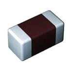
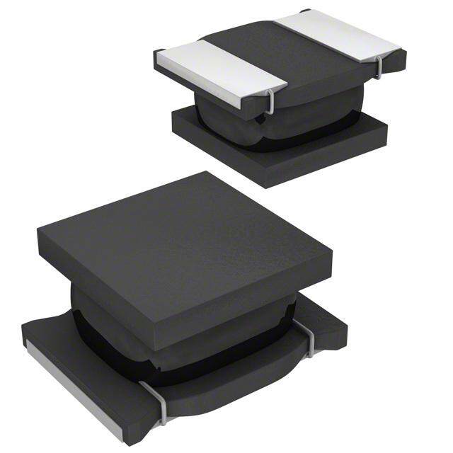
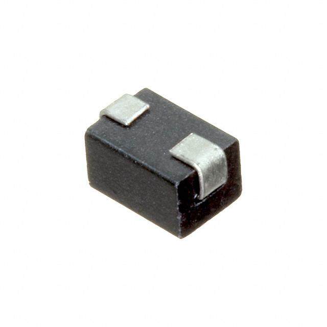
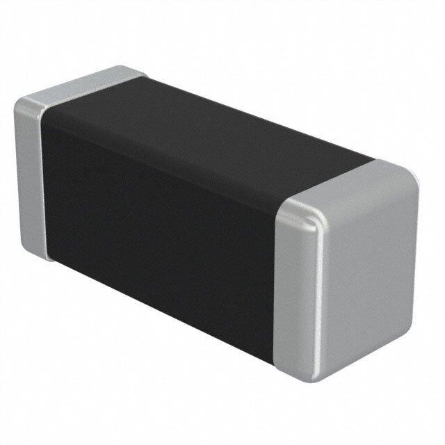
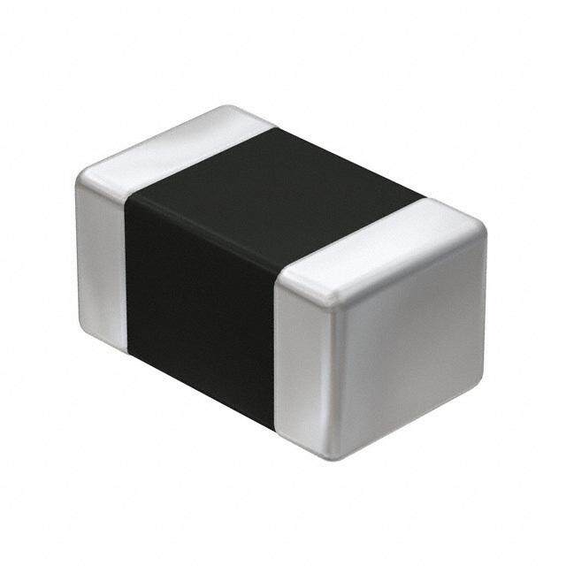
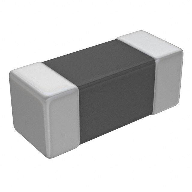
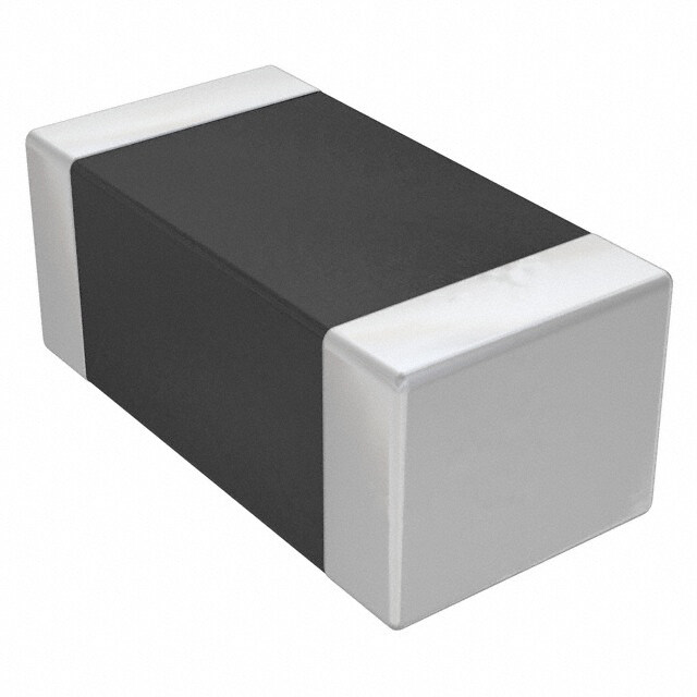
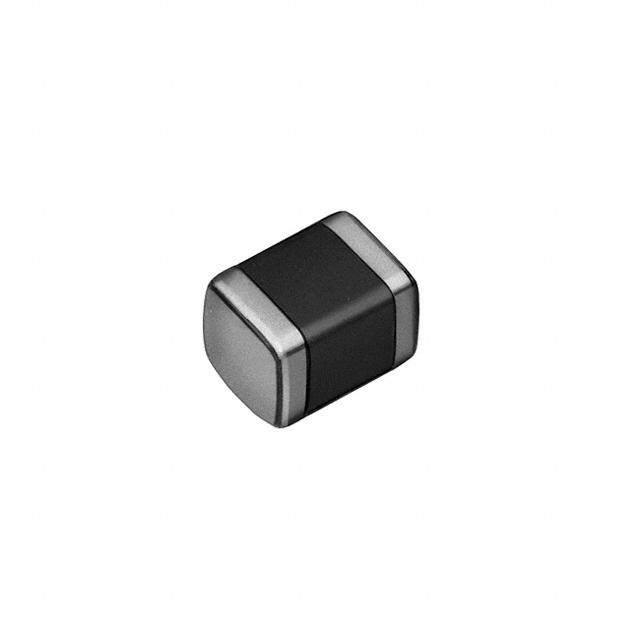
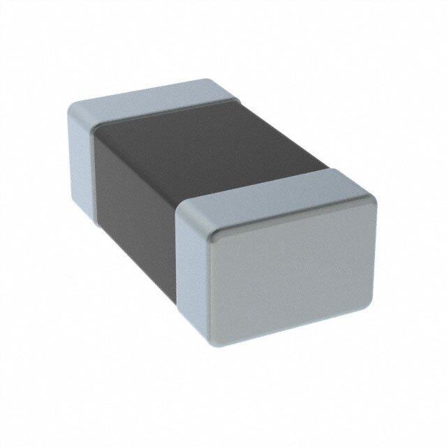
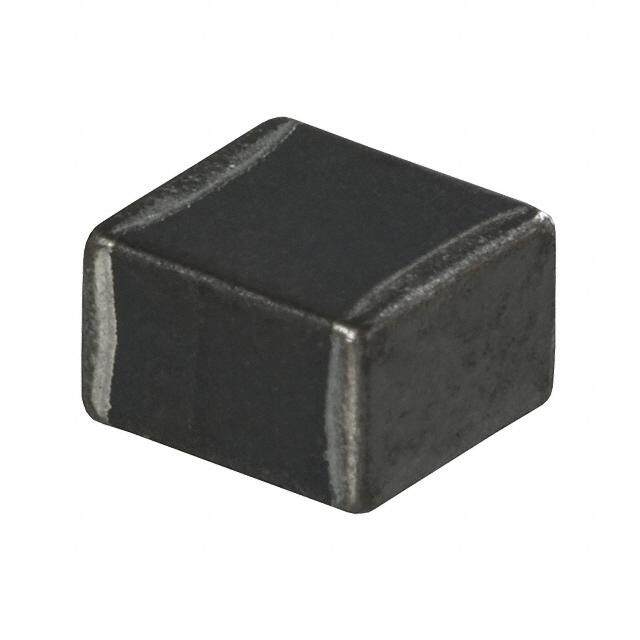
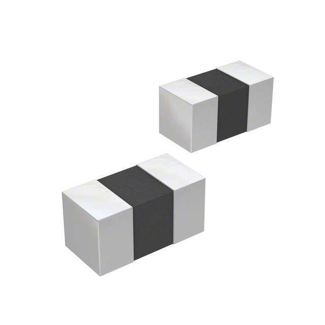
Taiyo Yuden(太阳诱电)的FBMH3225HM601NT是一款铁氧体磁珠芯片,属于表面贴装型噪声抑制元件。该型号尺寸为3.2×2.5mm,额定阻抗在100MHz下为600Ω,具有高阻抗特性,适用于抑制高频噪声。

其主要应用场景包括:智能手机、平板电脑、笔记本电脑等便携式电子设备中的电源线路和信号线路噪声滤波;数字电视、机顶盒、摄像机等消费类电子产品中高速信号线(如USB、HDMI、LCD接口)的电磁干扰(EMI)抑制;以及各类通信设备、汽车电子控制单元(ECU)、车载信息娱乐系统中的电源去耦和信号完整性保护。

FBMH3225HM601NT因其高可靠性、低直流电阻和优良的噪声吸收性能,特别适合对空间紧凑性和电气性能要求较高的精密电子设备。广泛用于DC-DC转换器输出端,防止高频噪声回馈至电源系统,提升整体电磁兼容性(EMC)。同时,该器件符合RoHS环保标准,适用于自动化贴片生产工艺,是现代高密度电子电路设计中常用的EMI对策元件。
| 参数 | 数值 |
| 产品目录 | |
| DC电阻(DCR) | 42 毫欧最大 |
| 描述 | FERRITE BEAD 600 OHM 1210EMI滤波珠子、芯片与阵列 HI CUR CHIP BD 1210 600OHMS 30% |
| 产品分类 | |
| 品牌 | Taiyo Yuden |
| 产品手册 | http://www.yuden.co.jp/ut/product/category/emisuppression/FBMH3225HM601NT.html |
| 产品图片 |
|
| rohs | 符合RoHS无铅 / 符合限制有害物质指令(RoHS)规范要求 |
| 产品系列 | EMI滤波珠子、芯片与阵列,Taiyo Yuden FBMH3225HM601NTFBM |
| 数据手册 | |
| 产品型号 | FBMH3225HM601NT |
| 不同频率时的阻抗 | 600 欧姆 @ 100MHz |
| 产品 | Ferrite Chip Beads |
| 产品培训模块 | http://www.digikey.cn/PTM/IndividualPTM.page?site=cn&lang=zhs&ptm=7323 |
| 产品目录绘图 |
|
| 产品目录页面 | |
| 产品种类 | EMI滤波珠子、芯片与阵列 |
| 其它名称 | 587-1755-6 |
| 包装 | Digi-Reel® |
| 商标 | Taiyo Yuden |
| 外壳宽度 | 1.6 mm |
| 外壳长度 | 3.2 mm |
| 外壳高度 | 1.6 mm |
| 大小/尺寸 | 0.126" 长 x 0.098" 宽(3.20mm x 2.50mm) |
| 安装类型 | 表面贴装 |
| 容差 | 30 % |
| 封装 | Reel |
| 封装/外壳 | 1210(3225 公制) |
| 封装/箱体 | 1210 (3225 metric) |
| 尺寸 | 1.6 mm W x 3.2 mm L x 1.6 mm H |
| 工作温度范围 | - 40 C to + 125 C |
| 工厂包装数量 | 1000 |
| 最大直流电流 | 3 A |
| 最大直流电阻 | 42 mOhms |
| 标准包装 | 1 |
| 测试频率 | 100 MHz |
| 滤波器类型 | 差模 - 单线 |
| 电容 | - |
| 端接类型 | SMD/SMT |
| 系列 | FBM |
| 阻抗 | 600 Ohms |
| 额定电流 | 3A |
| 高度(最大值) | 0.110"(2.80mm) |


- 商务部:美国ITC正式对集成电路等产品启动337调查
- 曝三星4nm工艺存在良率问题 高通将骁龙8 Gen1或转产台积电
- 太阳诱电将投资9.5亿元在常州建新厂生产MLCC 预计2023年完工
- 英特尔发布欧洲新工厂建设计划 深化IDM 2.0 战略
- 台积电先进制程称霸业界 有大客户加持明年业绩稳了
- 达到5530亿美元!SIA预计今年全球半导体销售额将创下新高
- 英特尔拟将自动驾驶子公司Mobileye上市 估值或超500亿美元
- 三星加码芯片和SET,合并消费电子和移动部门,撤换高东真等 CEO
- 三星电子宣布重大人事变动 还合并消费电子和移动部门
- 海关总署:前11个月进口集成电路产品价值2.52万亿元 增长14.8%
PDF Datasheet 数据手册内容提取
Notice for TAIYO YUDEN products Please read this notice before using the TAIYO YUDEN products. REMINDERS ■ Product information in this catalog is as of October 2013. All of the contents specified herein are subject to change without notice due to technical improvements, etc. Therefore, please check for the latest information carefully be- fore practical application or usage of the Products. Please note that TAIYO YUDEN CO., LTD. shall not be responsible for any defects in products or equipment incor- porating such products, which are caused under the conditions other than those specified in this catalog or indi- vidual specification. ■ Please contact TAIYO YUDEN CO., LTD. for further details of product specifications as the individual specification is available. ■ Please conduct validation and verification of products in actual condition of mounting and operating environment before commercial shipment of the equipment. ■ All electronic components or functional modules listed in this catalog are developed, designed and intended for use in general electronics equipment.(for AV, office automation, household, office supply, information service, telecommunications, (such as mobile phone or PC) etc.). Before incorporating the components or devices into any equipment in the field such as transportation,( automotive control, train control, ship control), transportation signal, disaster prevention, medical, public information network (telephone exchange, base station) etc. which may have direct influence to harm or injure a human body, please contact TAIYO YUDEN CO., LTD. for more detail in ad- vance. Do not incorporate the products into any equipment in fields such as aerospace, aviation, nuclear control, subma- rine system, military, etc. where higher safety and reliability are especially required. In addition, even electronic components or functional modules that are used for the general electronic equipment, if the equipment or the electric circuit require high safety or reliability function or performances, a sufficient reliabil- ity evaluation check for safety shall be performed before commercial shipment and moreover, due consideration to install a protective circuit is strongly recommended at customer's design stage. ■ The contents of this catalog are applicable to the products which are purchased from our sales offices or distribu- tors (so called“ TAIYO YUDEN’s official sales channel”). It is only applicable to the products purchased from any of TAIYO YUDEN’ s official sales channel. ■ Please note that TAIYO YUDEN CO., LTD. shall have no responsibility for any controversies or disputes that may occur in connection with a third party's intellectual property rights and other related rights arising from your usage of products in this catalog. TAIYO YUDEN CO., LTD. grants no license for such rights. ■ Caution for export Certain items in this catalog may require specific procedures for export according to“ Foreign Exchange and For- eign Trade Control Law” of Japan,“ U.S. Export Administration Regulations”, and other applicable regulations. Should you have any question or inquiry on this matter, please contact our sales staff. 14
CHIP BEAD INDUCTORS FOR POWER LINES (FB SERIES M TYPE) CHIP BEAD INDUCTORS FOR POWER LINES (FB SERIES M TYPE) WAVE REFLOW ■PARTS NUMBER *Operating Temp. : -40~+125℃(Including self-generated heat) F B △ M J 3 2 1 6 H S 8 0 0 - T △ △=Blank space ① ② ③ ④ ⑤ ⑥ ⑦ ⑧ ⑨ ①Series name ⑤Material Code Series name Code Material FB Ferrite bead HS Refer to impedance curves HM for material differences ②Shape HL Code Shape M Rectangular chip ⑥Nominal impedance Code Nominal impedance[Ω] ③Characteristics (example) N Code Characteristics 330 33 O J Standard 111 110 IS H High Impedance type 132 1300 E S ④Dimensions(L×W) ⑦Impedance tolerance U P Code Type(inch) Dimensions Code Impedance tolerance P (L×W)[mm] - ±25% R E 1608 1608(0603) 1.6×0.8 N ±30% S 2125 2125(0805) 2.0×1.25 SIO 2012 2012(0805) ⑧Packaging N 2016 2016(0806) 2.0×1.6 Code Packaging 3216 3216(1206) 3.2×1.6 T Taping C O 3225 3225(1210) 3.2×2.5 M 4516 4516(1806) 4.5×1.6 ⑨Internal code P 4525 4525(1810) 4.5×2.5 Code Internal code O 4532 4532(1812) 4.5×3.2 △ Standard N E N T ■STANDARD EXTERNAL DIMENSIONS / STANDARD QUANTITY S / Recommended Land Patterns Type A B C FE Surface Mounting FBMJ1608 1.0 1.0 1.0 R FBMJ2125 1.4 1.2 1.65 R ・Mounting and soldering conditions should be FBMJ3216 1.4 2.2 2.0 IT checked beforehand. FBMJ4516 1.75 3.5 2.0 E FBMH1608 1.0 1.0 1.0 B FBMH2012 1.4 1.2 1.65 E FBMH2016 1.4 1.2 2.0 A FBMH3216 1.4 2.2 2.0 D FFBBMMHH43521265 11.7.45 32..52 22..09 IN FBMH4525 1.75 3.5 2.9 D FBMH4532 1.75 3.5 3.7 U Unit:mm C T O Standard quantity [pcs] Type L W T e R Paper tape Embossed tape S FB MJ1608 1.6±0.2 0.8±0.2 0.8±0.2 0.3±0.2 4000 - (0603) (0.063±0.008) (0.031±0.008) (0.031±0.008) (0.012±0.008) FB MJ2125 2.0±0.2 1.25±0.2 0.85±0.2 0.5±0.3 4000 - (0805) (0.079±0.008) (0.049±0.008) (0.033±0.008) (0.020±0.012) FB MJ3216 3.2±0.3 1.6±0.2 1.1±0.2 0.5±0.3 - 2000 (1206) (0.126±0.012) (0.063±0.008) (0.043±0.008) (0.020±0.012) FB MJ4516 4.5±0.3 1.6±0.2 1.1±0.2 0.5±0.3 - 2000 (1806) (0.177±0.012) (0.063±0.008) (0.043±0.008) (0.020±0.012) FB MH1608 1.6±0.1 0.8±0.1 0.8±0.1 0.3±0.15 4000 - (0603) (0.063±0.004) (0.031±0.004) (0.031±0.004) (0.012±0.006) FB MH2012 2.0±0.2 1.25±0.2 0.85±0.2 0.5±0.3 4000 - (0805) (0.079±0.008) (0.049±0.008) (0.033±0.008) (0.020±0.012) FB MH2016 2.0±0.2 1.6±0.2 1.6±0.2 0.5±0.3 - 2000 (0806) (0.079±0.008) (0.063±0.008) (0.063±0.008) (0.020±0.012) FB MH3216 3.2±0.3 1.6±0.2 1.6±0.2 0.5±0.3 - 2000 (1206) (0.126±0.012) (0.063±0.008) (0.063±0.008) (0.020±0.012) FB MH3225 3.2±0.3 2.5±0.3 2.5±0.3 0.5±0.3 - 1000 (1210) (0.126±0.012) (0.098±0.012) (0.098±0.012) (0.020±0.012) FB MH4516 4.5±0.3 1.6±0.2 1.6±0.2 0.5±0.3 - 2000 (1806) (0.177±0.012) (0.063±0.008) (0.063±0.008) (0.020±0.012) FB MH4525 4.5±0.4 2.5±0.3 2.5±0.3 0.9±0.6 - 1000 (1810) (0.177±0.016) (0.098±0.012) (0.098±0.012) (0.035±0.024) FB MH4532 4.5±0.4 3.2±0.3 3.2±0.3 0.9±0.6 - 2000 (1812) (0.177±0.016) (0.126±0.012) (0.126±0.012) (0.035±0.024) Unit:mm(inch) chipbeads_e-E02R01 ▶ This catalog contains the typical specification only due to the limitation of space. When you consider the purchase of our products, please check our specification. For details of each product (characteristics graph, reliability information, precautions for use, and so on), see our Web site (http://www.ty-top.com/) . 14 109
■PARTS NUMBER Standard type ●FB MJ1608 Nominal impedance Measuring frequency DC Resistance Rated current Thickness Parts number EHS Impedance tolerance (Ω) [MHz] [Ω](max.) [A](max.) [mm] FB MJ1608HS280NT RoHS 28 ±30% 100 0.007 4.0 0.8±0.2 FB MJ1608HM230NT RoHS 23 ±30% 100 0.007 4.0 0.8±0.2 ●FB MJ2125 Nominal impedance Measuring frequency DC Resistance Rated current Thickness Parts number EHS Impedance tolerance (Ω) [MHz] [Ω](max.) [A](max.) [mm] FB MJ2125HS250NT RoHS 25 ±30% 100 0.004 6.0 0.85±0.2 FB MJ2125HS420-T RoHS 42 ±25% 100 0.008 4.0 0.85±0.2 FB MJ2125HM210NT RoHS 21 ±30% 100 0.004 6.0 0.85±0.2 FB MJ2125HM330-T RoHS 33 ±25% 100 0.008 4.0 0.85±0.2 FB MJ2125HL8R0NT RoHS 8 ±30% 100 0.008 4.0 0.85±0.2 ●FB MJ3216 Nominal impedance Measuring frequency DC Resistance Rated current Thickness Parts number EHS Impedance tolerance (Ω) [MHz] [Ω](max.) [A](max.) [mm] FB MJ3216HS480NT RoHS 48 ±30% 100 0.005 6.0 1.1±0.2 FB MJ3216HS800-T RoHS 80 ±25% 100 0.010 4.0 1.1±0.2 FB MJ3216HM380NT RoHS 38 ±30% 100 0.005 6.0 1.1±0.2 N FB MJ3216HM600-T RoHS 60 ±25% 100 0.010 4.0 1.1±0.2 O FB MJ3216HL160NT RoHS 16 ±30% 100 0.012 4.0 1.1±0.2 IS E ●FB MJ4516 S Parts number EHS Nominal impedance Impedance tolerance Measuring frequency DC Resistance Rated current Thickness U (Ω) [MHz] [Ω](max.) [A](max.) [mm] P FB MJ4516HS720NT RoHS 72 ±30% 100 0.007 6.0 1.1±0.2 P FB MJ4516HS111-T RoHS 110 ±25% 100 0.014 4.0 1.1±0.2 R E FB MJ4516HM560NT RoHS 56 ±30% 100 0.007 6.0 1.1±0.2 S FB MJ4516HM900-T RoHS 90 ±25% 100 0.014 4.0 1.1±0.2 S FB MJ4516HL230NT RoHS 23 ±30% 100 0.014 3.5 1.1±0.2 IO N High impedance type C ●FB MH1608 O Parts number EHS Nominal impedance Impedance tolerance Measuring frequency DC Resistance Rated current Thickness (Ω) [MHz] [Ω](max.) [A](max.) [mm] M FB MH1608HM470-T RoHS 47 ±25% 100 0.020 3.5 0.8±0.1 P O FB MH1608HM600-T RoHS 60 ±25% 100 0.025 3.0 0.8±0.1 N FB MH1608HM101-T RoHS 100 ±25% 100 0.035 2.5 0.8±0.1 E FB MH1608HM151-T RoHS 150 ±25% 100 0.050 2.1 0.8±0.1 N FB MH1608HM221-T RoHS 220 ±25% 100 0.070 1.8 0.8±0.1 T FB MH1608HM331-T RoHS 330 ±25% 100 0.130 1.2 0.8±0.1 S FB MH1608HM471-T RoHS 470 ±25% 100 0.150 1.0 0.8±0.1 / FB MH1608HM601-T RoHS 600 ±25% 100 0.170 0.9 0.8±0.1 F FB MH1608HM102-T RoHS 1000 ±25% 100 0.350 0.6 0.8±0.1 E R FB MH1608HL300-T RoHS 30 ±25% 100 0.028 2.6 0.8±0.1 R FB MH1608HL600-T RoHS 60 ±25% 100 0.045 2.1 0.8±0.1 IT FB MH1608HL121-T RoHS 120 ±25% 100 0.130 1.2 0.8±0.1 E FB MH1608HL221-T RoHS 220 ±25% 100 0.170 0.9 0.8±0.1 B FB MH1608HL331-T RoHS 330 ±25% 100 0.210 0.8 0.8±0.1 E FB MH1608HL471-T RoHS 470 ±25% 100 0.350 0.6 0.8±0.1 A FB MH1608HL601-T RoHS 600 ±25% 100 0.450 0.5 0.8±0.1 D IN ●FB MH2012 D Parts number EHS Nominal impedance Impedance tolerance Measuring frequency DC Resistance Rated current Thickness U (Ω) [MHz] [Ω](max.) [A](max.) [mm] C FB MH2012HM800-T RoHS 80 ±25% 100 0.025 2.7 0.85±0.2 T FB MH2012HM121-T RoHS 120 ±25% 100 0.032 2.5 0.85±0.2 O FB MH2012HM221-T RoHS 220 ±25% 100 0.060 2.0 0.85±0.2 R FB MH2012HM331-T RoHS 330 ±25% 100 0.080 1.8 0.85±0.2 S ●FB MH2016 Nominal impedance Measuring frequency DC Resistance Rated current Thickness Parts number EHS Impedance tolerance (Ω) [MHz] [Ω](max.) [A](max.) [mm] FB MH2016HM121NT RoHS 120 ±30% 100 0.015 4.5 1.6±0.2 FB MH2016HM251NT RoHS 250 ±30% 100 0.050 2.0 1.6±0.2 ●FB MH3216 Nominal impedance Measuring frequency DC Resistance Rated current Thickness Parts number EHS Impedance tolerance (Ω) [MHz] [Ω](max.) [A](max.) [mm] FB MH3216HM221NT RoHS 220 ±30% 100 0.020 4.0 1.6±0.2 FB MH3216HM501NT RoHS 500 ±30% 100 0.070 2.0 1.6±0.2 ●FB MH3225 Nominal impedance Measuring frequency DC Resistance Rated current Thickness Parts number EHS Impedance tolerance (Ω) [MHz] [Ω](max.) [A](max.) [mm] FB MH3225HM601NT RoHS 600 ±30% 100 0.042 3.0 2.5±0.3 FB MH3225HM102NT RoHS 1000 ±30% 100 0.100 2.0 2.5±0.3 FB MH3225HM202NT RoHS 2000 ±30% 100 0.130 1.2 2.5±0.3 chipbeads_e-E02R01 ▶ This catalog contains the typical specification only due to the limitation of space. When you consider the purchase of our products, please check our specification. For details of each product (characteristics graph, reliability information, precautions for use, and so on), see our Web site (http://www.ty-top.com/) . 110 14
■PARTS NUMBER ●FB MH4516 Nominal impedance Measuring frequency DC Resistance Rated current Thickness Parts number EHS Impedance tolerance (Ω) [MHz] [Ω](max.) [A](max.) [mm] FB MH4516HM851NT RoHS 850 ±30% 100 0.100 1.5 1.6±0.2 ●FB MH4525 Nominal impedance Measuring frequency DC Resistance Rated current Thickness Parts number EHS Impedance tolerance (Ω) [MHz] [Ω](max.) [A](max.) [mm] FB MH4525HM102NT RoHS 1000 ±30% 100 0.060 3.0 2.5±0.3 FB MH4525HM162NT RoHS 1600 ±30% 100 0.130 2.0 2.5±0.3 ●FB MH4532 Nominal impedance Measuring frequency DC Resistance Rated current Thickness Parts number EHS Impedance tolerance (Ω) [MHz] [Ω](max.) [A](max.) [mm] FB MH4532HM681-T RoHS 680 ±25% 100 0.028 4.0 3.2±0.3 FB MH4532HM132-T RoHS 1300 ±25% 100 0.060 3.0 3.2±0.3 FB MH4532HM202-T RoHS 2000 ±25% 100 0.130 1.3 3.2±0.3 ●High current type Nominal impedance Measuring frequency DC Resistance Rated current Thickness Parts number EHS Impedance tolerance (Ω) [MHz] [Ω](max.) [A](max.) [mm] FB MJ1608HS220NTR RoHS 22 ±30% 100 0.004 7.5 0.8±0.2 N FB MJ1608HS280NTR RoHS 28 ±30% 100 0.006 6.0 0.8±0.2 O FFBB MMJJ11660088HHMM128300NNTTRR RRooHHSS 1283 ±±3300%% 110000 00..000046 76..50 00..88±±00..22 ISE S U P P R E S S IO N C O M P O N E N T S / F E R R IT E B E A D IN D U C T O R S chipbeads_e-E02R01 ▶ This catalog contains the typical specification only due to the limitation of space. When you consider the purchase of our products, please check our specification. For details of each product (characteristics graph, reliability information, precautions for use, and so on), see our Web site (http://www.ty-top.com/) . 14 111
■ ELECTRICAL CHARACTERISTICS ■ FB MJ1608 ■ FB MJ2125 ■ FB MJ3216 N O IS E S U P P R E FB MJ3216HL160NT S 70 S IO 60 N 50 C 40 O 30 M 20 P O 10 N 0 E N T ■ FB MJ4516 S / F E R R IT E B E A D IN D U C T FB MJ4516HL230NT 100 O 90 R S 80 70 60 50 40 30 20 10 0 ▶ This catalog contains the typical specification only due to the limitation of space. When you consider the purchase of our products, please check our specification. For details of each product (characteristics graph, reliability information, precautions for use, and so on), see our Web site (http://www.ty-top.com/) . 112 14
■ ELECTRICAL CHARACTERISTICS Standard type ■ FB MH1608 FB MH1608HM470-T FB MH1608HM600-T FB MH1608HM101-T FB MH1608HM151-T 200 200 200 600 180 180 180 160 160 160 500 140 140 140 400 120 120 120 Z 100 100 100 300 R 8600 Z R 8600 Z R 8600 200 Z R 4200 X 4200 X 4200 X 100 X 01 10 100 1000 10000 01 10 100 1000 10000 01 10 100 1000 10000 01 10 100 1000 10000 FB MH1608HM221-T FB MH1608HM331-T FB MH1608HM471-T FB MH1608HM601-T 600 600 1600 1600 1400 1400 500 500 1200 1200 400 400 1000 1000 N 300 Z 300 Z R 800 800 Z O 200 R 200 X 640000 Z R 640000 R ISE 100 X 100 200 X 200 X S 01 10 100 1000 10000 01 10 100 1000 10000 01 10 100 1000 10000 01 10 100 1000 10000 UP P R E S 1600 FB MH1608HM102-T 300 FB MH1608HL300-T 300 FB MH1608HL600-T 600 FB MH1608HL121-T SIO 1400 N 250 250 500 1200 Z C 1000 200 200 R 400 Z O Z 800 R 150 150 300 R M 640000 X 100 Z R 100 X 200 X PO 200 50 X 50 100 N E 01 10 100 1000 10000 01 10 100 1000 10000 01 10 100 1000 10000 01 10 100 1000 10000 N T S / F FB MH1608HL221-T FB MH1608HL331-T FB MH1608HL471-T FB MH1608HL601-T E 1000 1400 2000 2500 R 900 1800 R 800 1200 1600 2000 IT 760000 Z R 1080000 Z 11420000 Z 1500 Z E B 500 R 1000 R E 400 600 800 1000 R A 300 400 600 D 210000 X 200 X 420000 X 500 X IN 01 10 100 1000 10000 01 10 100 1000 10000 01 10 100 1000 10000 01 10 100 1000 10000 DU C T ■ FBMH2012 O FB MH2012HM800-T FB MH2012HM121-T FB MH2012HM221-T FB MH2012HM331-T R 400 400 400 800 S 350 350 350 300 300 300 Z 600 250 250 250 Z 200 200 200 R 400 R 150 150 Z 150 100 Z R 100 R 100 X 200 X 50 X 50 X 50 01 10 100 1000 10000 01 10 100 1000 10000 01 10 100 1000 10000 01 10 100 1000 10000 ■ FB MH2016 ■ FB MH3216 FB MH2016HM121NT FB MH2016HM251NT FB MH3216HM221NT FB MH3216HM501NT 200 800 350 800 180 300 116400 600 250 600 112000 Z R 400 210500 Z R 400 Z R 8600 200 Z R 100 200 X 40 50 X 20 X X 01 10 100 1000 10000 01 10 100 1000 01 10 100 1000 10000 01 10 100 1000 ▶ This catalog contains the typical specification only due to the limitation of space. When you consider the purchase of our products, please check our specification. For details of each product (characteristics graph, reliability information, precautions for use, and so on), see our Web site (http://www.ty-top.com/) . 14 113
■ ELECTRICAL CHARACTERISTICS Standard type ■ FB MH3225 ■ FB MH4516 FB MH3225HM601NT FB MH3225HM102NT FB MH3225HM202NT FB MH4516HM851NT 1200 1200 2500 1200 1000 1000 2000 1000 800 800 800 R R 1500 Z 600 600 Z Z R 600 R 1000 400 Z 400 400 200 X 200 X 500 X 200 X 01 10 100 1000 01 10 100 1000 01 10 100 1000 01 10 100 1000 ■ FB MH4525 ■ FB MH4532 FB MH4525HM102NT FB MH4525HM162NT FB MH4532HM681-T FB M4532HM132-T 1800 1800 1800 1800 1600 1600 1600 1600 1400 1400 1400 1400 1000 1000 1000 1000 NO 1820000 Z R 1820000 Z R 1820000 1820000 Z R ISE 640000 X 640000 X 640000 Z R 640000 X S 200 200 200 X 200 U 01 10 100 1000 01 10 100 1000 01 10 100 1000 01 10 100 1000 P P R E ■ High current type S SIO 2500 FB M4532HM202-T 30 FB MJ1608HS220NTR 40 FB J1608HM180NTR N 35 2000 25 30 C O 1500 20 Z 25 Z Z M R 15 R 20 R P 1000 10 15 O 10 N 500 5 X 5 X X EN 01 10 100 1000 01 10 100 1000 10000 01 10 100 1000 10000 T S / F E R R IT E B E A D IN D U C T O R S ▶ This catalog contains the typical specification only due to the limitation of space. When you consider the purchase of our products, please check our specification. For details of each product (characteristics graph, reliability information, precautions for use, and so on), see our Web site (http://www.ty-top.com/) . 114 14
CHIP BEAD INDUCTORS FOR POWER LINES (FB SERIES M TYPE) ■PACKAGING ①Minimum Quantity Standard Quantity[pcs] Type Paper Tape Embossed Tape 1608(0603) 4000 - 2125(0805) 4000 - 2012(0805) 4000 - 2016(0806) - 2000 3216(1206) - 2000 3225(1210) - 1000 4516(1806) - 2000 4525(1810) - 1000 4532(1812) - 2000 ②Tape Material ●Card board carrier tape Top tape Base tape Chip Filled Sprocket hole Bottom tape Chip cavity Chip ●Embossed tape Top tape Chip Filled Sprocket hole Base tape Chip cavity Chip ③Taping Dimensions ●Paper tape (0.315 inches wide) ▶ This catalog contains the typical specification only due to the limitation of space. When you consider the purchase of our products, please check our specification. For details of each product (characteristics graph, reliability information, precautions for use, and so on), see our Web site (http://www.ty-top.com/) . chipbeads_pack_e-E02R01
Chip Cavity Insertion Pitch Tape Thickness Type A B F T FBMJ1608 1.0±0.2 1.8±0.2 4.0±0.2 1.1max FBMH1608 (0.039±0.008) (0.071±0.008) (0.157±0.008) (0.043max) (0603) FBMJ2125 1.5±0.2 2.3±0.2 4.0±0.2 1.1max FBMH2012 (0.059±0.008) (0.091±0.008) (0.157±0.008) (0.043max) (0805) Unit : mm(inch) ●Embossed tape (0.315 inches wide) Chip Cavity Insertion Pitch Tape Thickness Type A B F K T FBMH2016 1.8±0.2 2.2±0.2 4.0±0.2 2.6max 0.6max (0806) (0.071±0.008) (0.087±0.008) (0.157±0.008) (0.102max) (0.024max) FBMJ3216 1.9±0.2 3.5±0.2 4.0±0.2 1.5max 0.3max (1206) (0.075±0.008) (0.138±0.008) (0.157±0.008) (0.059max) (0.012max) FBMH3216 1.9±0.2 3.5±0.2 4.0±0.2 2.6max 0.6max (1206) (0.075±0.008) (0.138±0.008) (0.157±0.008) (0.102max) (0.024max) FBMH3225 2.8±0.2 3.5±0.2 4.0±0.2 4.0max 0.6max (1210) (0.110±0.008) (0.138±0.008) (0.157±0.008) (0.157max) (0.024max) Unit : mm(inch) ●Embossed tape (0.472 inches wide) Chip Cavity Insertion Pitch Tape Thickness Type A B F K T FBMJ4516 1.9±0.2 4.9±0.2 4.0±0.2 1.5max 0.3max (1806) (0.075±0.008) (0.193±0.008) (0.157±0.008) (0.059max) (0.012max) FBMH4516 1.9±0.2 4.9±0.2 4.0±0.2 2.6max 0.6max (1806) (0.075±0.008) (0.193±0.008) (0.157±0.008) (0.102max) (0.024max) FBMH4525 2.9±0.2 4.9±0.2 4.0±0.2 4.0max 0.6max (1810) (0.114±0.008) (0.193±0.008) (0.157±0.008) (0.157max) (0.024max) FBMH4532 3.6±0.2 4.9±0.2 8.0±0.2 4.0max 0.6max (1812) (0.142±0.008) (0.193±0.008) (0.315±0.008) (0.157max) (0.024max) Unit : mm(inch) ▶ This catalog contains the typical specification only due to the limitation of space. When you consider the purchase of our products, please check our specification. For details of each product (characteristics graph, reliability information, precautions for use, and so on), see our Web site (http://www.ty-top.com/) . chipbeads_pack_e-E02R01
④Leader and Blank portion ⑤Reel size 2.0±0.5 t (0.079±0.020) φ13.0±0.5 (φ0.512±0.020) φd φD φ21.0±0.8 R1.0 (φ0.827±0.031) W Type φD φd W t FBMJ1608 10.0±1.5 FBMJ2125 (0.394±0.059) FBMJ3216 14.0±1.5 FBMJ4516 (0.551±0.059) FBMH1608 180+0/-3 60+1/-0 2.5max FBMH2012 (7.09+0/-0.118 ) (2.36+0.039/-0 ) (0.098max) 10.0±1.5 FBMH2016 (0.394±0.059) FBMH3216 FBMH3225 FBMH4516 14.0±1.5 FBMH4525 (0.551±0.059) 330±2.0 100±1.0 14.0±2.0 3.0max FBMH4532 (12.99±0.080) (3.94±0.039) (0.551±0.080) (1.181max) Unit : mm(inch) ⑥Top tape strength The top tape requires a peel-off force of 0.1 to 0.7N in the direction of the arrow as illustrated below. ▶ This catalog contains the typical specification only due to the limitation of space. When you consider the purchase of our products, please check our specification. For details of each product (characteristics graph, reliability information, precautions for use, and so on), see our Web site (http://www.ty-top.com/) . chipbeads_pack_e-E02R01
CHIP BEAD INDUCTORS FOR POWER LINE (FB SERIES M TYPE) ■RELIABILITY DATA 1. Operating Temperature Range -40℃~+125℃ Specified Value Including self-generated heat 2. Storage Temperature Range Specified Value -40℃~+85℃ Test Methods and *Note: -5 to +40℃ in taped packaging Remarks 3. Impedance Specified Value Within the specified tolerance Test Methods and Measuring equipment : Impedance analyzer (HP4291A) or its equivalent Remarks Measuring frequency : 100±1 MHz 4. DC Resistance Specified Value Within the specified range Test Methods and Four-terminal method Remarks Measuring equipment : Milliohm High-Tester 3226 (Hioki Denki) or its equivalent 5. Rated Current Specified Value Within the specified range 6. Vibration Appearance : No significant abnormality Specified Value Impedance change : Within ±30% of the initial value According to JIS C 0040. Vibration type : A Test Methods and Time : 2 hrs each in X,Y, and Z directions Total: 6 hrs Remarks Frequency range : 10 to 55 to 10Hz (/min.) Amplitude : 1.5 mm (shall not exceed acceleration 196m/s2) Mounting method : Soldering onto PC board 7. Solderability Specified Value 90% or more of immersed surface of terminal electrode shall be covered with fresh solder. Solder temperature : 230±5℃ Test Methods and Immersion time : 4±1 sec. Remarks Preconditioning : Immersion into flux. Immersion and Removal speed : 25mm/sec. 8. Resistance to Soldering Heat Appearance : No significant abnormality Specified Value Impedance change : Within ±30% of the initial value Preheating : 150℃ for 3 min. Resistance to Soldering Heat : 260±5℃ Test Methods and Duration : 10±0.5 sec. Remarks Preconditioning : Immersion into flux. Immersion and Removal speed : 25mm/sec. Recovery : 2 to 3 hrs of recovery under the standard condition after the test. ▶ This catalog contains the typical specification only due to the limitation of space. When you consider the purchase of our products, please check our specification. For details of each product (characteristics graph, reliability information, precautions for use, and so on), see our Web site (http://www.ty-top.com/) . chipbeads_reli_e-E02R01
9. Thermal Shock Appearance : No significant abnormality Specified Value Impedance change : Within+50/-10% of the initial value According to JIS C 0025. Conditions for 1 cycle Step Temperature (℃) Duration (min.) 1 -40±3℃ 30±3 2 Room Temperature Within 3 Test Methods and 3 85±2℃ 30±3 Remarks 4 Room Temperature Within 3 Number of cycles : 100 Mounting method : Soldering onto PC board Recovery : 2 to 3 hrs of recovery under the standard condition after the removal from test chamber. 10. Resistance to Humidity (steady state) Appearances : No significant abnormality Specified Value Impedance change : Within ±30% of the initial value Temperature : 40±2℃ Humidity : 90 to 95% RH Test Methods and Duration : 500+24/-0 Remarks Mounting method : Soldering onto PC board Recovery : 2 to 3 hrs of recovery under the standard condition after the removal from test chamber. 11. Loading under Damp Heat Appearance No significant abnormality Specified Value Impedance change Within ±30% of the initial value Temperature : 40±2℃ Humidity : 90 to 95%RH Test Methods and Applied current : Rated current Remarks Duration : 500+24/-0 hrs Mounting method : Soldering onto PC board Recovery : 2 to 3hrs of recovery under the standard condition after the removal from test chamber. 12. High Temperature Loading Test Appearance : No significant abnormality Specified Value Impedance change : Within ±30% of the initial value Temperature : 85±2℃ Duration : 500+24/-0 hrs Test Methods and Applied current : Rated current Remarks Mounting method : Soldering onto PC board Recovery : 2 to 3 hrs of recovery under the standard condition after the removal from test chamber. 13. Bending Strength Specified Value Appearance : No mechanical damage. Warp : 2mm Testing board : Glass epoxy-resin substrate Thickness : 0.8mm Test Methods and Remarks ▶ This catalog contains the typical specification only due to the limitation of space. When you consider the purchase of our products, please check our specification. For details of each product (characteristics graph, reliability information, precautions for use, and so on), see our Web site (http://www.ty-top.com/) . chipbeads_reli_e-E02R01
14. Adhesion of Electrode Specified Value No separation or indication of separation of electrode. Applied force : 5N Duration : 10 sec. Test Methods and Remarks Note on standard condition: "standard condition" referred to herein is defined as follows: 5 to 35℃ of temperature, 45 to 85% relative humidity and 86 to 106kPa of air pressure. When there are questions concerning measurement results: In order to provide correlation data, the test shall be conducted under condition of 20±2℃ of temperature, 60 to 70% relative humidity and 86 to 106kPa of air pressure. Unless otherwise specified, all the tests are conducted under the "standard condition." ▶ This catalog contains the typical specification only due to the limitation of space. When you consider the purchase of our products, please check our specification. For details of each product (characteristics graph, reliability information, precautions for use, and so on), see our Web site (http://www.ty-top.com/) . chipbeads_reli_e-E02R01
CHIP BEAD INDUCTORS FOR POWER LINE (FB SERIES M TYPE) ■PRECAUTIONS 1. Circuit Design ◆Operating environment 1. The products described in this specification are intended for use in general electronic equipment, (office supply equipment, telecommunications systems, measuring equipment, and household equipment). They are not intended for use in mission-critical equipment or systems requiring special quality and high reliability (traffic systems, safety equipment, aerospace systems, nuclear control systems and medical equipment including life-support systems,) where product failure might result in loss of life, injury or Precautions damage. For such uses, contact TAIYO YUDEN Sales Department in advance. ◆Rated current 1. Rated current of this product is shown in this catalogue, but please be sure to have the base board designed with adequate inspection in case of the generation of heat becomes high within the rated current range when the base board is in high resistance or in bad heating conditions. 2. PCB Design ◆Land pattern design Precautions 1. Please refer to a recommended land pattern. 3. Considerations for automatic placement ◆Adjustment of mounting machine Precautions 1. Excessive impact load should not be imposed on the products when mounting onto the PC boards. 2. Mounting and soldering conditions should be checked beforehand. Technical ◆Adjustment of mounting machine considerations 1. When installing products, care should be taken not to apply distortion stress as it may deform the products. 4. Soldering ◆Wave soldering 1. Please refer to the specifications in the catalog for a wave soldering. ◆Reflow soldering 1. Please contact any of our offices for a reflow soldering, and refer to the recommended condition specified. ◆Lead free soldering 1. When using products with lead free soldering, we request to use them after confirming adhesion, temperature of resistance to soldering heat, etc. sufficiently. Precautions ◆Preheating when soldering Heating : The temperature difference between soldering and remaining heat should not be greater than 150℃. Cooling : The temperature difference between the components and cleaning process should not be greater than 100℃. ◆Recommended conditions for using a soldering iron Put the soldering iron on the land-pattern. Soldering iron's temperature - Below 350℃ Duration - 3 seconds or less The soldering iron should not directly touch the inductor. ◆Wave, Reflow, Lead free soldering 1. If products are used beyond the range of the recommended conditions, heat stresses may deform the products, and consequently degrade the reliability of the products. 【Recommended reflow condition】 Technical considerations ◆Preheating when soldering 1. There is a case that products get damaged by a heat shock. ◆Recommended conditions for using a soldering iron 1. If products are used beyond the range of the recommended conditions, heat stresses may deform the products, and consequently degrade the reliability of the products. ▶ This catalog contains the typical specification only due to the limitation of space. When you consider the purchase of our products, please check our specification. For details of each product (characteristics graph, reliability information, precautions for use, and so on), see our Web site (http://www.ty-top.com/) . chipbeads_prec_e-E02R01
5. Handling ◆Handling 1. Keep the inductors away from all magnets and magnetic objects. ◆Setting PC boards 1. When setting a chip mounted base board, please make sure that there is no residual stress to the chip by distortion in the board or at screw part. Precautions ◆Breakaway PC boards (splitting along perforations) 1. When splitting the PC board after mounting inductors, care should be taken not to give any stresses of deflection or twisting to the board. 2. Board separation should not be done manually, but by using the appropriate devices. ◆Mechanical considerations 1. Please do not give the inductors any excessive mechanical shocks. ◆Handling 1. There is a case that a characteristic varies with magnetic influence. ◆Setting PC boards Technical 1. There is a case that a characteristic varies with residual stress. considerations ◆Breakaway PC boards (splitting along perforations) 1. Planning pattern configurations and the position of products should be carefully performed to minimize stress. ◆Mechanical considerations 1. There is a case to be damaged by a mechanical shock. 6. Storage conditions ◆Storage 1. To maintain the solderability of terminal electrodes and to keep the packing material in good condition, temperature and humidity in the storage area should be controlled. ・Recommended conditions Precautions Ambient temperature 0~40℃ Humidity Below 70% RH The ambient temperature must be kept below 30℃. Even under ideal storage conditions, solderability of products electrodes may decrease as time passes. For this reason, inductors should be used within 6 months from the time of delivery. ◆Storage Technical 1. Under a high temperature and humidity environment, problems such as reduced solderability caused by oxidation of terminal electrodes considerations and deterioration of taping/packaging materials may take place. ▶ This catalog contains the typical specification only due to the limitation of space. When you consider the purchase of our products, please check our specification. For details of each product (characteristics graph, reliability information, precautions for use, and so on), see our Web site (http://www.ty-top.com/) . chipbeads_prec_e-E02R01
Mouser Electronics Authorized Distributor Click to View Pricing, Inventory, Delivery & Lifecycle Information: T aiyo Yuden: FBMH1608HL121-T FBMH1608HL221-T FBMH1608HL300-T FBMH1608HL331-T FBMH1608HL471-T FBMH1608HL600-T FBMH1608HL601-T FBMH1608HM101-T FBMH1608HM102-T FBMH1608HM151-T FBMH1608HM221-T FBMH1608HM331-T FBMH1608HM470-T FBMH1608HM471-T FBMH1608HM600-T FBMH1608HM601-T FBMH2012HM121-T FBMH2012HM221-T FBMH2012HM331-T FBMH2012HM800-T FBMH2016HM251NT FBMH3216HM501NT FBMH3225HM102NT FBMH3225HM202NT FBMH3225HM601NT FBMH4516HM851NT FBMH4525HM102NT FBMH4525HM162NT FBMH4532HM132-T FBMH4532HM202-T FBMH4532HM681-T FBMJ1608HM230NT FBMJ1608HS280NT FBMJ2125HL8R0NT FBMJ2125HM210NT FBMJ2125HM330-T FBMJ2125HS250NT FBMJ2125HS420-T FBMJ3216HL160NT FBMJ3216HM380NT FBMJ3216HM600-T FBMJ3216HS480NT FBMJ3216HS800-T FBMJ4516HL230NT FBMJ4516HM560NT FBMJ4516HM900-T FBMJ4516HS111-T FBMJ4516HS720NT FBMH2016HM121NT FBMJ1608HS280NTR FBMJ1608HS220NTR FBMH3216HM221NT FBMJ1608HM180NTR FBMJ1608HM230NTR FBMH4525HM102NTV FBMJ4516HM900-TV FBMH1608HM101-TV FBMJ2125HM330-TV FBMH1608HL121-TV FBMH1608HM221-TV FBMJ3216HL160NTV FBMJ1608HM230NTV FBMJ3216HS480NTV FBMH3225HM102NTV FBMJ4516HM560NTV FBMJ2125HM210NTV FBMH1608HL331-TV FBMH1608HM151-TV FBMH2016HM121NTV FBMH1608HL300-TV FBMJ4516HS111-TV FBMJ1608HS220NTW FBMH1608HL600-TV FBMH1608HM601-TV FBMH4516HM851NTV FBMH1608HM102-TV FBMH2012HM331-TV FBMJ3216HM380NTV FBMH1608HM471-TV FBMH2016HM251NTV FBMH1608HL471-TV FBMH1608HM600-TV FBMH1608HL221-TV FBMH3225HM202NTV FBMH1608HL601-TV FBMJ3216HM600-TV FBMH3225HM601NTV FBMJ4516HL230NTV FBMJ1608HM230NTW FBMJ3216HS800-TV FBMJ1608HS280NTW FBMH2012HM221-TV FBMJ1608HS280NTV FBMJ4516HS720NTV FBMJ2125HS420-TV FBMH2012HM800-TV FBMJ1608HM180NTW FBMJ2125HS250NTV FBMH1608HM331-TV FBMH2012HM121-TV