 Datasheet下载
- 型号: F750J687MRC
- 制造商: Nichicon
- 库位|库存: xxxx|xxxx
- 要求:
| 数量阶梯 | 香港交货 | 国内含税 |
| +xxxx | $xxxx | ¥xxxx |
查看当月历史价格
查看今年历史价格
F750J687MRC产品简介:
ICGOO电子元器件商城为您提供F750J687MRC由Nichicon设计生产,在icgoo商城现货销售,并且可以通过原厂、代理商等渠道进行代购。 F750J687MRC价格参考。NichiconF750J687MRC封装/规格:钽电容器, 680µF 保形涂层 钽电容器 6.3V 2824(7260 公制) 120 毫欧。您可以下载F750J687MRC参考资料、Datasheet数据手册功能说明书,资料中有F750J687MRC 详细功能的应用电路图电压和使用方法及教程。
AVX Corporation的F750J687MRC是一款钽电容器,常用于对电容稳定性、可靠性和工作温度范围有较高要求的电子设备中。该型号具有较高的电容值和良好的频率特性,适用于电源滤波、去耦、信号耦合等电路设计。

其主要应用场景包括:

1. 通信设备:如基站、路由器和交换机,用于电源管理模块中,提升电源稳定性和抗干扰能力。
2. 工业控制系统:如PLC、工业计算机和自动化设备,用于确保电路在复杂电磁环境中的稳定运行。
3. 汽车电子:如车载导航、ECU(电子控制单元)和传感器模块,满足汽车工作环境对温度和可靠性的严苛要求。
4. 消费类电子产品:如高端音视频设备、数码相机和便携式游戏机,用于提升信号处理质量和电源效率。
5. 医疗设备:如监护仪、成像设备和便携式诊断仪器,确保设备运行的稳定性和安全性。

该电容器具有体积小、容量大、寿命长等优点,适合高密度电路设计,广泛应用于需要高性能电容解决方案的领域。
| 参数 | 数值 |
| 产品目录 | |
| 描述 | CAP TANT 680UF 6.3V 20% 2824 |
| ESR(等效串联电阻) | 120 毫欧 |
| 产品分类 | |
| 品牌 | Nichicon |
| 数据手册 | |
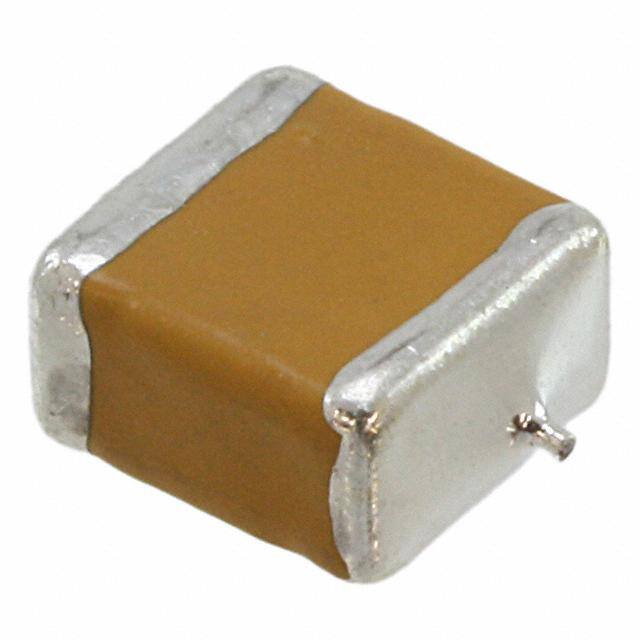
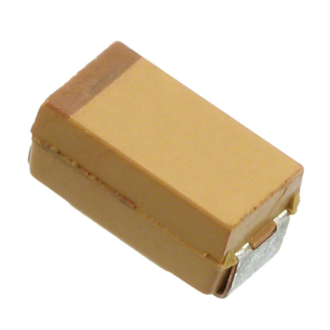
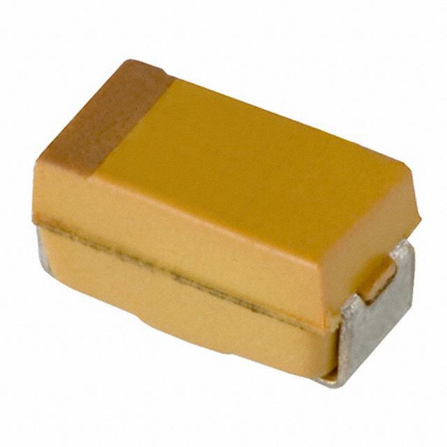
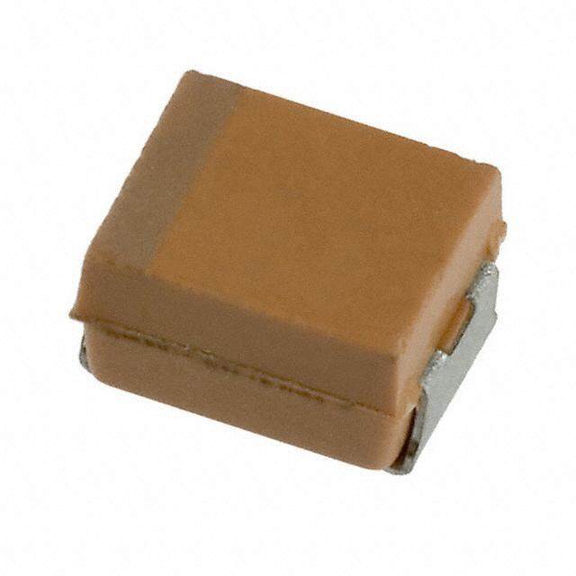
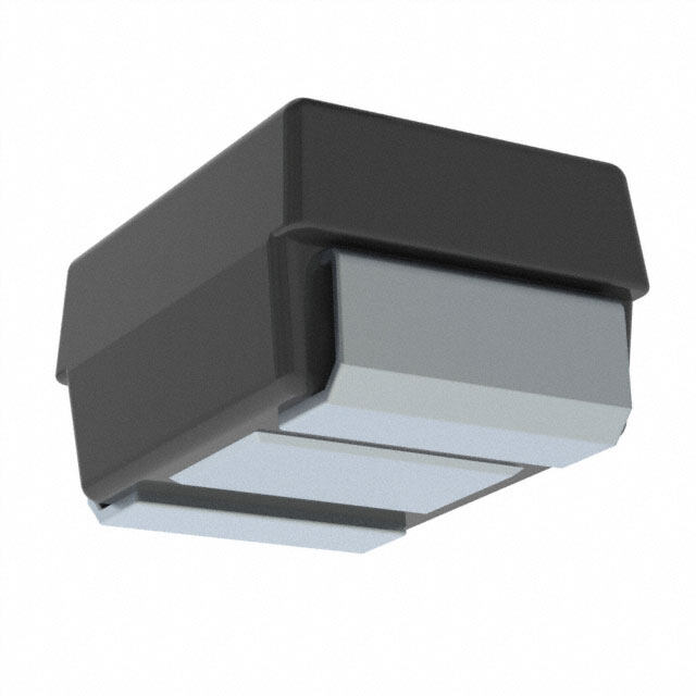
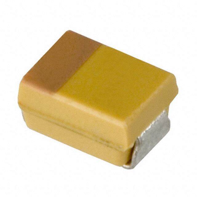
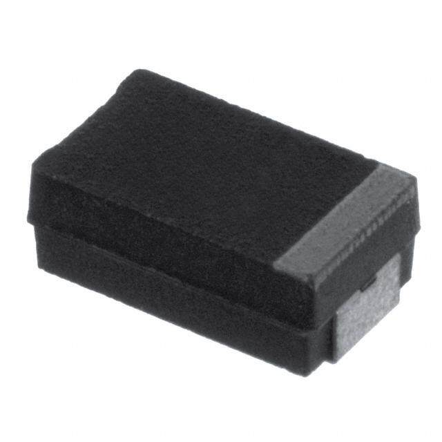
| 产品图片 |
|
| 产品型号 | F750J687MRC |
| PCN制造商信息 | |
| rohs | 无铅 / 符合限制有害物质指令(RoHS)规范要求 |
| 产品系列 | F75 Frameless™ |
| 不同温度时的使用寿命 | - |
| 产品培训模块 | http://www.digikey.cn/PTM/IndividualPTM.page?site=cn&lang=zhs&ptm=24878 |
| 产品目录绘图 |
|
| 产品目录页面 | |
| 其它名称 | 493-3366-1 |
| 制造商尺寸代码 | R |
| 包装 | 剪切带 (CT) |
| 大小/尺寸 | 0.283" 长 x 0.236" 宽(7.20mm x 6.00mm) |
| 安装类型 | 表面贴装 |
| 容差 | ±20% |
| 封装/外壳 | 2824(7260 公制) |
| 工作温度 | -55°C ~ 125°C |
| 引线间距 | - |
| 标准包装 | 1 |
| 特性 | 通用 |
| 电压-额定 | 6.3V |
| 电容 | 680µF |
| 类型 | 保形涂层 |
| 高度-安装(最大值) | 0.150"(3.80mm) |


PDF Datasheet 数据手册内容提取
F72/F75 Series Low Profile and High CV Conformal Coated Chip FEATURES • Compliant to the RoHS2 directive 2011/65/EU • SMD Conformal • Small and low profile LEAD-FREE COMPATI- BLE COMPONENT APPLICATIONS • Smartphone • Mobile phone • Wireless module CASE DIMENSIONS:millimeters (inches) • Hearing aid Code EIA Code EIA Metric L W H A B D* F72 Case Dimensions F72 F75 M 2824 7260-20 7.20±0.30 6.00±0.30 2.00 Max. 1.30±0.40 3.80±0.60 6.20 (0.283±0.012) (0.236±0.012) (0.079 Max) (0.051±0.016) (0.150±0.024) (0.244) 7.20±0.30 6.00±0.30 1.20±0.30 1.30±0.40 3.80±0.60 6.20 H R 2824 7260-15 A H (0.283±0.012) (0.236±0.012) (0.047±0.012) (0.051±0.016) (0.150±0.024) (0.244) BD A B F75 Case Dimensions D 7.10±0.30 3.20±0.30 2.50±0.30 1.30±0.30 3.60±0.60 6.00 L L C 2 8 1 3 7 1 3 2 - 2 8 (0.280±0.012) (0.126±0.012) (0.098±0.012) (0.051±0.012) (0.142±0.024) (0.236) W Solder electrode W D 2914 7343-31 7.30±0.30 4.30±0.30 2.80±0.30 1.30±0.40 3.90±0.60 6.40 (0.287±0.012) (0.136±0.012) (0.110±0.012) (0.051±0.016) (0.153±0.024) (0.252) 7.20±0.30 6.00±0.30 2.80 Max. 1.30±0.40 3.80±0.60 6.20 M 2824 7260-28 (0.283±0.012) (0.236±0.012) (0.110 Max) (0.051±0.016) (0.150±0.024) (0.244) 7.20±0.30 6.00±0.30 3.50±0.30 1.30±0.40 3.80±0.60 6.20 R 2824 7260-38 (0.283±0.012) (0.236±0.012) (0.138±0.012) (0.051±0.016) (0.150±0.024) (0.244) 7.10±0.30 3.20±0.30 2.00 Max. 1.30±0.30 3.60±0.60 6.00 U 2813 7132-20 (0.280±0.012) (0.126±0.012) (0.079 Max) (0.051±0.012) (0.142±0.024) (0.236) HOW TO ORDER *D dimension only for reference F72 1A 107 M R (cid:2) (cid:2)(cid:2)(cid:2) AQ2 or Q2 Type Rated Capacitance Tolerance Case Packaging Specification Single Face Voltage Code K = ±10% Size See Tape & Reel Suffix Electrode pF code: 1st two digits M = ±20% See Packaging Section AH1 = Low ESR represent significant figures, table 3rd digit represents multiplier above (number of zeros to follow) F75 1C 157 M D (cid:2) AQ2 Type Rated Capacitance Tolerance Case Packaging Single Voltage Code K = ±10% Size See Tape & Reel Face pF code: 1st two digits M = ±20% See Packaging Section Electrode represent significant figures, table 3rd digit represents multiplier above (number of zeros to follow) TECHNICAL SPECIFICATIONS Category Temperature Range: -55 to +125°C Rated Temperature: +85°C Capacitance Tolerance: ±20%, ±10% at 120Hz Dissipation Factor: Refer to next page ESR 100kHz: Refer to next page Leakage Current: After 1 minute’s application of rated voltage, leakage current at 20°C is not more than 0.01CV or 0.5μA, whichever is greater. After 1 minute’s application of rated voltage, leakage current at 85°C is not more than 0.1CV or 5μA, whichever is greater. After 1 minute’s application of derated voltage, leakage current at 125°C is not more than 0.125CV or 6.3μA, whichever is greater. Capacitance Change By Temperature +15% Max. at +125°C +10% Max. at +85°C -10% Max. at -55°C 040919 173
F72/F75 Series Low Profile and High CV Conformal Coated Chip CAPACITANCE AND RATED VOLTAGE RANGE (LETTER DENOTES CASE SIZE) F72 F75 Capacitance Rated Voltage Capacitance Rated Voltage µF Code 4V (0G) 6.3V (0J) 10V (1A) 16V (1C) µF Code 4V (0G) 6.3V (0J) 10V (1A) 16V (1C) 33 336 R 68 686 C 47 476 R R 100 107 C 68 686 R R R 150 157 C D 100 107 R R R 220 227 C C/D R 150 157 R R R 330 337 C C/D D 220 227 R R R M 470 477 C/D D/U R/U 330 337 R R M 680 687 D D/R 470 477 M 1000 108 D/R R/U 680 687 M 1500 158 R 1000 108 M/M(AH1) M 2200 228 R M 1500 158 M Released ratings Please contact to your local AVX sales office when these series are being designed in your application. RATINGS & PART NUMBER REFERENCE F72 Rated DF ESR 100kHz RMS Current (mA) *1 AVX Case Capacita n c e Voltage DCL @ 120Hz @ 100kHz ΔC/C MSL P a r t N o . S i z e ( μ F ) (V) ( μ A ) (%) (Ω) 2 5 º C 8 5 º C 1 2 5 º C (%) 4 Volt F720G107#RC R 100 4 4.0 8 0.70 463 417 185 * 3 F720G157#RC R 150 4 6.0 10 0.70 463 417 185 * 3 F720G227#RC R 220 4 8.8 12 0.70 463 417 185 * 3 F720G337#RC R 330 4 13.2 12 0.70 463 417 185 * 3 6.3 Volt F720J686#RC R 68 6.3 4.3 6 0.75 447 402 179 * 3 F720J107#RC R 100 6.3 6.3 8 0.70 463 417 185 * 3 F720J157#RC R 150 6.3 9.5 10 0.70 463 417 185 * 3 F720J227#RC R 220 6.3 13.9 12 0.70 463 417 185 * 3 F720J337#RC R 330 6.3 20.8 12 0.70 463 417 185 * 3 F720J108#MCAQ2 M 1000 6.3 63.0 30 0.14 1118 1006 447 ±15 3 F720J108#MCAH1Q2 M 1000 6.3 63.0 30 0.075 1528 1375 611 ±15 3 F720J158#MCAQ2 M 1500 6.3 95.0 45 0.14 1118 1006 447 ±20 3 10 Volt F721A476#RC R 47 10 4.7 6 0.80 433 390 173 * 3 F721A686#RC R 68 10 6.8 6 0.75 447 402 179 * 3 F721A107#RC R 100 10 10.0 8 0.70 463 417 185 * 3 F721A157#RC R 150 10 15.0 10 0.70 463 417 185 * 3 F721A227#RC R 220 10 22.0 12 0.70 463 417 185 * 3 F721A477#MCAQ2 M 470 10 47.0 30 0.14 1118 1006 447 ±15 3 F721A687#MCAQ2 M 680 10 68.0 35 0.14 1118 1006 447 ±20 3 F721A108#MCAQ2 M 1000 10 200 45 0.14 1118 1006 447 ±20 3 16 Volt F721C336#RC R 33 16 5.3 6 0.90 408 367 163 * 3 F721C476#RC R 47 16 7.5 6 0.80 433 390 173 * 3 F721C686#RC R 68 16 10.9 6 0.75 447 402 179 * 3 F721C227#MCAQ2 M 220 16 35.2 12 0.20 935 842 374 ±20 3 F721C337#MCAQ2 M 330 16 52.8 45 0.20 935 842 374 ±20 3 F75 Rated DF ESR 100kHz RMS Current (mA) *1 AVX Case Capacita n c e Voltage DCL @ 120Hz @ 100kHz ΔC/C MSL P a r t N o . S i z e ( μ F ) (V) ( μ A ) (%) (Ω) 2 5 º C 8 5 º C 1 2 5 º C (%) 4 Volt F750G337#CC C 330 4 13.2 10 0.15 856 771 343 * 3 F750G477#CC C 470 4 18.8 14 0.12 957 862 383 * 3 F750G477#DC D 470 4 18.8 14 0.12 1118 1006 447 * 3 F750G687#DC D 680 4 27.2 18 0.12 1118 1006 447 * 3 F750G108#DC D 1000 4 40.0 24 0.12 1118 1006 447 * 3 F750G108#RC R 1000 4 40.0 24 0.12 1443 1299 577 * 3 F750G158#RC R 1500 4 60.0 30 0.12 1443 1299 577 * 3 F750G228#RC R 2200 4 88.0 45 0.07 1890 1701 756 * 3 6.3 Volt F750J227#CC C 220 6.3 13.9 10 0.20 742 667 297 * 3 F750J337#CC C 330 6.3 20.8 10 0.15 856 771 343 * 3 F750J337#DC D 330 6.3 20.8 10 0.15 1000 900 400 * 3 F750J477#DC D 470 6.3 29.6 14 0.12 1118 1006 447 * 3 174 040919
F72/F75 Series Low Profile and High CV Conformal Coated Chip RATINGS & PART NUMBER REFERENCE Rated DF ESR 100kHz RMS Current (mA) *1 AVX Case Capacita n c e Voltage DCL @ 120Hz @ 100kHz ΔC/C MSL P a r t N o . S i z e ( μ F ) (V) ( μ A ) (%) (Ω) 2 5 º C 8 5 º C 1 2 5 º C (%) F750J477#UC U 470 6.3 29.6 15 0.10 1049 944 420 * 3 F750J687#DC D 680 6.3 42.8 18 0.12 1118 1006 447 * 3 F750J687#RC R 680 6.3 42.8 18 0.12 1443 1299 577 * 3 F750J108#RC R 1000 6.3 63.0 24 0.12 1443 1299 577 * 3 F750J108#UCAQ2 U 1000 6.3 126 40 0.15 856 771 343 ±20 3 F750J228#MCAQ2 M 2200 6.3 139 60 0.08 1581 1423 632 ±20 3 10 Volt F751A157#CC C 150 10 15.0 10 0.22 707 636 283 * 3 F751A227#CC C 220 10 22.0 10 0.20 742 667 297 * 3 F751A227#DC D 220 10 22.0 10 0.20 866 779 346 * 3 F751A337#DC D 330 10 33.0 10 0.15 1000 900 400 * 3 F751A477#RC R 470 10 47.0 14 0.12 1443 1299 577 * 3 F751A477#UCAQ2 U 470 10 94.0 30 0.15 856 771 343 ±20 3 16 Volt F751C686#CC C 68 16 10.9 10 0.22 707 636 283 * 3 F751C107#CC C 100 16 16.0 10 0.22 707 636 283 * 3 F751C157#DC D 150 16 24.0 10 0.22 826 743 330 * 3 F751C227#RC R 220 16 35.2 10 0.20 1118 1006 447 * 3 *1: ΔC/C Marked “*” #: "M" for ±20% tolerance, "K" for ± 10% tolerance. Moisture Sensitivity Level (MSL) is defined according to J-STD-020. Item F72/F75 All Case (%) Damp Heat ±10 Temperature cycles ±5 Resistance soldering heat ±5 Surge ±5 Endurance ±10 QUALIFICATION TABLE F72/75 series (Temperature range -55ºC to +125ºC) TEST Condition At 40°C, 90 to 95% R.H., 500 hours (No voltage applied) D a m p H e a t Capacitance Change ........... Refer to page 174 (*1) ( S t e a d y S t a t e ) Dissipation Factor ................ Initial specified value or less Leakage Current .................. Initial specified value or less At -55°C / +125°C, 30 minutes each, 5 cycles T e m p e r a t u r e C y c l e s Capacitance Change ........... Refer to page 174 (*1) Dissipation Factor ................ Initial specified value or less Leakage Current .................. Initial specified value or less 10 seconds reflow at 260°C, 10 seconds immersion at 260°C. Resistance to Capacitance Change ........... Refer to page 174 (*1) S o l d e r i n g H e a t Dissipation Factor ................ Initial specified value or less Leakage Current .................. Initial specified value or less After application of surge voltage in series with a 33Ω resistor at the rate of 30 seconds ON, 30 seconds OFF, for 1000 successive test cycles at 85ºC, capacitors shall meet the characteristic requirements in the table above. S u r g e Capacitance Change ........... Refer to page 174 (*1) Dissipation Factor ................ Initial specified value or less Leakage Current .................. Initial specified value or less After 2000 hours’ application of rated voltage at 85°C, capacitors shall meet the characteristic requirements in the table above. E n d u r a n c e Capacitance Change ........... Refer to page 174 (*1) Dissipation Factor ................ Initial specified value or less Leakage Current .................. Initial specified value or less After applying the pressure load of 5N for 10±1 seconds horizontally to the center of capacitor side body Shear Test which has no electrode and has been soldered beforehand on a substrate, there shall be found neither exfoliation nor its sign at the terminal electrode. Keeping a capacitor surface-mounted on a substrate upside down and supporting the substrate at both of the opposite bottom points 45mm apart from the center of capacitor, the pressure strength is Terminal Strength applied with a specified jig at the center of substrate so that the substrate may bend by 1mm as illustrated. Then, there shall be found no remarkable abnormality on the capacitor terminals. 040919 175
F72/F75 Series Low Profile and High CV Conformal Coated Chip AVX SOLID ELECTROLYTIC CAPACITOR ROADMAP SERIES LINE UP: CONFORMAL Ta MnO 2 176 040919