ICGOO在线商城 > 电阻器 > 芯片电阻 - 表面安装 > ERX-2HJ3R9H
 Datasheet下载
- 型号: ERX-2HJ3R9H
- 制造商: Panasonic Corporation
- 库位|库存: xxxx|xxxx
- 要求:
| 数量阶梯 | 香港交货 | 国内含税 |
| +xxxx | $xxxx | ¥xxxx |
查看当月历史价格
查看今年历史价格
ERX-2HJ3R9H产品简介:
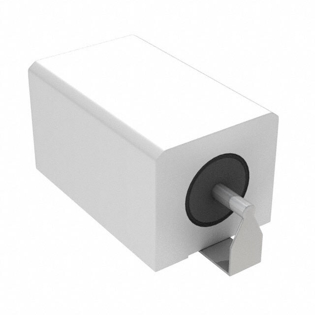
ICGOO电子元器件商城为您提供ERX-2HJ3R9H由Panasonic Corporation设计生产,在icgoo商城现货销售,并且可以通过原厂、代理商等渠道进行代购。 ERX-2HJ3R9H价格参考。Panasonic CorporationERX-2HJ3R9H封装/规格:芯片电阻 - 表面安装, 3.9 Ohms ±5% 2W 金属薄膜 芯片电阻 SMD 压平 J 弯曲轴引线 耐燃,安全 金属薄膜。您可以下载ERX-2HJ3R9H参考资料、Datasheet数据手册功能说明书,资料中有ERX-2HJ3R9H 详细功能的应用电路图电压和使用方法及教程。
型号为ERX-2HJ3R9H的Panasonic Electronic Components芯片电阻属于表面贴装型电阻,具备高精度和高稳定性的特点,适用于对电路性能要求较高的电子设备。该电阻具有良好的耐热性和可靠性,适用于自动化贴片生产工艺。

该型号电阻的典型应用场景包括:

1. 消费类电子产品:如智能手机、平板电脑、笔记本电脑等便携设备中,用于电源管理、信号调节等电路中。

2. 工业控制设备:如PLC、传感器、工业自动化系统中的信号采集与处理电路。

3. 通信设备:用于路由器、交换机、基站设备中的电源模块和信号处理电路。

4. 汽车电子系统:如车载导航、车载娱乐系统、电池管理系统(BMS)等,满足汽车电子对稳定性和可靠性的较高要求。

5. 医疗电子设备:如便携式监护仪、诊断设备中的精密测量与控制电路。

该电阻的高精度特性使其适用于需要稳定电流控制或信号反馈的电路设计中,是各类高可靠性电子系统中常用的基础元器件。
| 参数 | 数值 |
| 产品目录 | |
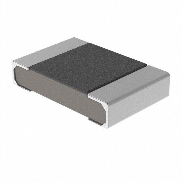
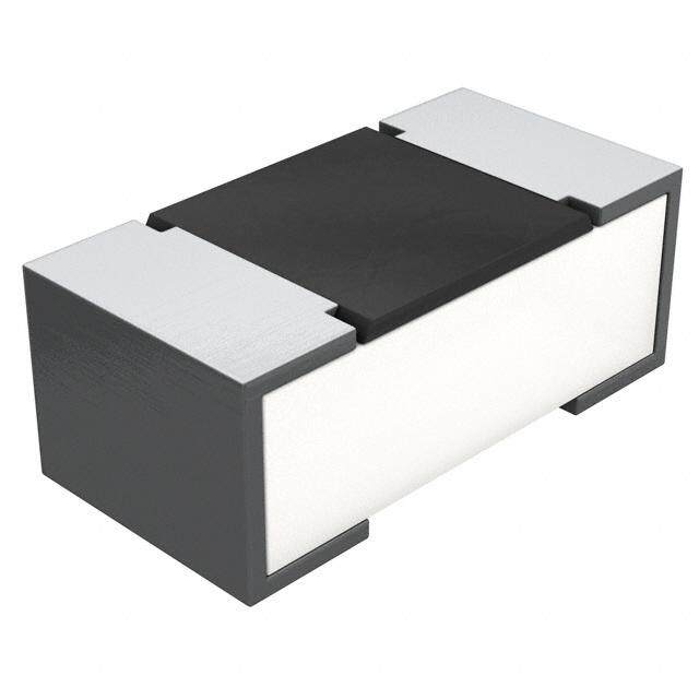
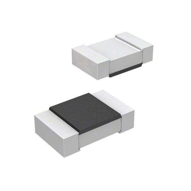
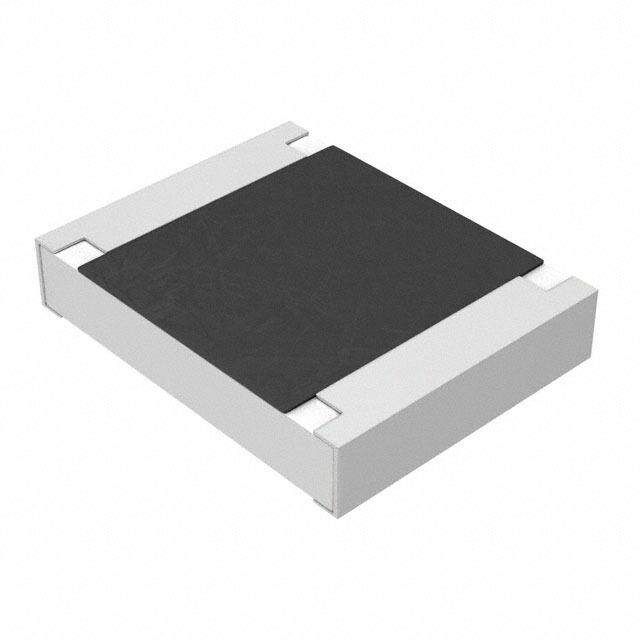
| 描述 | RES 3.9 OHM 2W 5% J-BEND SMD |
| 产品分类 | |
| 品牌 | Panasonic Electronic Components |
| 数据手册 | |
| 产品图片 |
|
| 产品型号 | ERX-2HJ3R9H |
| rohs | 含铅 / 不符合限制有害物质指令(RoHS)规范要求 |
| 产品系列 | ERX |
| 产品目录绘图 |
|
| 产品目录页面 | |
| 供应商器件封装 | SMD |
| 其它名称 | PRX2W3.9CT |
| 功率(W) | 2W |
| 包装 | 剪切带 (CT) |
| 大小/尺寸 | 0.472" 长 x 0.252" 宽(12.00mm x 6.40mm) |
| 容差 | ±5% |
| 封装/外壳 | SMD 压平 J 弯曲轴引线 |
| 成分 | 金属薄膜 |
| 标准包装 | 1 |
| 温度系数 | ±350ppm/°C |
| 特性 | 耐燃 |
| 电阻(Ω) | 3.9 |
| 端子数 | 2 |
| 高度 | 0.236"(6.00mm) |


- 商务部:美国ITC正式对集成电路等产品启动337调查
- 曝三星4nm工艺存在良率问题 高通将骁龙8 Gen1或转产台积电
- 太阳诱电将投资9.5亿元在常州建新厂生产MLCC 预计2023年完工
- 英特尔发布欧洲新工厂建设计划 深化IDM 2.0 战略
- 台积电先进制程称霸业界 有大客户加持明年业绩稳了
- 达到5530亿美元!SIA预计今年全球半导体销售额将创下新高
- 英特尔拟将自动驾驶子公司Mobileye上市 估值或超500亿美元
- 三星加码芯片和SET,合并消费电子和移动部门,撤换高东真等 CEO
- 三星电子宣布重大人事变动 还合并消费电子和移动部门
- 海关总署:前11个月进口集成电路产品价值2.52万亿元 增长14.8%


PDF Datasheet 数据手册内容提取
Fixed Metal (Oxide) Film Resistors, Surface Mount Type Fixed Metal (Oxide) Film Resistors, Surf ace Mount Type ERG(X)1H (1 W) Type: ERG(X)2H (2 W) ■ Features ● Non-fl ammable ● High Reliability ● RoHS compliant ■ Packaging Methods, Land Pattern, Soldering Conditions and Safety Precautions Please see Data Files ■ Explanation of Part Numbers Ex.1 : ERX type 1 2 3 4 5 6 7 8 9 10 (cid:38) (cid:51) (cid:57) (cid:19) (cid:41) (cid:59) (cid:43) (cid:18) (cid:51) (cid:17) (cid:41) Product Code Power Rating Style · Specification Resistance Resistance Value Packaging Methods Metal Film at 70 °C Surface Mount Tolerance The first two digits Code Packaging Type ERX H Resistors 1 1 W Type J ± 5 % are significant Enbossed Carrier Taping 2 2 W G ± 2 % figures of resistance 8 mm pitch, 2,000 pcs. ERX1H and the third one H “Z”, “Q” is added according to resistance. denotes number of Enbossed Carrier Taping ERX2H Type Resistance Resistance Value Range ((cid:63)) zeros following. 12 mm pitch, 1,000 pcs. Tolerance ERX(cid:60)HQ ERX(cid:60)HZ ERX(cid:60)H Decimal point is ±5 % 22 m to 82 m 0.10 to 0.18 0.20 to 9.1 expressed by ERX1H ±2 % — 0.10 to 0.91 1.0 to 9.1 (Ex.) 1R0 : 1.0 (cid:63) ±5 % 22 m to 82 m 0.10 to 0.20 0.22 to 9.1 ERX2H ±2 % — 0.10 to 0.91 1.0 to 9.1 The above example 1 shows a metal fi lm resistor SMD type, 2 W power rating, resistance value of 1.0 Ω, tolerance ±5 %, and embossed taping. Ex.2 : ERG type 1 2 3 4 5 6 7 8 9 10 (cid:38) (cid:51) (cid:40) (cid:19) (cid:41) (cid:43) (cid:18) (cid:17) (cid:19) (cid:41) Product Code Power Rating Style · Specification Resistance Resistance Value Packaging Methods Metal Oxide at 70 °C Surface Mount Tolerance The first two digits are Code Packaging Type ERG H Film Resistors 1 1 W Type J ± 5 % significant figures of Enbossed Carrier Taping 2 2 W G ± 2 % resistance and the third 8 mm pitch, 2,000 pcs. ERG1H one denotes number of H Type Resistance Resistance Value Range ((cid:63)) zDeercoism faoll lpowoiinntg i.s E12n bmomss epditc Cha, r1r,ie0r0 0Ta ppcinsg. ERG2H Tolerance ERG(cid:59)H expressed by ±5 % ERG1H 10 to 10 k (Ex.) 102 : 1.0 k(cid:63) ±2 % ±5 % ERG2H 10 to 10 k ±2 % The above example 2 shows a metal oxide fi lm resistor SMD type, 2 W power rating, resistance value of 1.0 kΩ, tolerance ±5 %,and embossed taping. Design and specifi cations are each subject to change without notice. Ask factory for the current technical specifi cations before purchase and/or use. Should a safety concern arise regarding this product, please be sure to contact us immediately. 02 Aug. 2013
Fixed Metal (Oxide) Film Resistors, Surface Mount Type ■ ■ Construction Dimensions in mm (not to scale) L W Metal (Oxide) fi lm Ceramic core End cap H P A B Dimensions (mm) Type P L W H A B Terminal Insulation Ceramic case ERG(X)1H 12.5+1.0 9.0±0.5 5.6±0.3 5.0±0.2 1.5±0.3 3.0±1.0 coating –0.5 ERG(X)2H 15.0+1.0 12.0±0.5 6.4±0.3 5.8±0.2 1.5±0.3 4.0±1.0 –0.5 ■ Ratings Resistance Power Dielectric Res. Range (Ω)(2) Standard Rating Withs tandi ng T.C.R. Type Tol. Resistance at 70 °C Voltage (×10–6/°C) (%)(2) Value (W)(1) (VAC) min.(3) max. 22 m 39 m ±1000 J (±5) 47 m 82 m ±500 ERG(X)1H 1 1000 E12 G (±2) 0.1 10 k ±350 J (±5) 22 m 39 m ±1000 J (±5) 47 m 82 m ±500 ERG(X)2H 2 1000 E12 G (±2) 0.1 10 k ±350 J (±5) (1) Rated Continuous Working Voltage (RCWV) shall be determined from RCWV=√Power Rating × Resistance Value. (2) Resistance tolerance and resistance range is of use besides range listed, please inquire. (3) As for the low resistance value range, “Q” or “Z” is given to the part number.(Refer to the explanation of part numbers.) Power Derating Curve 120 –55 °C 70 °C For resistors operated in ambient temperatures above 100 70 °C, power rating shall be derated in accordance %) with the fi gure on the right. ad ( 80 o 60 L d e 40 at R 20 0 –60 –40–20 0 20 40 60 80 100120140160180200220240 Ambient Temperature (°C) Design and specifi cations are each subject to change without notice. Ask factory for the current technical specifi cations before purchase and/or use. Should a safety concern arise regarding this product, please be sure to contact us immediately. 02 Aug. 2013