 Datasheet下载
- 型号: ERB-SD0R50U
- 制造商: Panasonic Corporation
- 库位|库存: xxxx|xxxx
- 要求:
| 数量阶梯 | 香港交货 | 国内含税 |
| +xxxx | $xxxx | ¥xxxx |
查看当月历史价格
查看今年历史价格
ERB-SD0R50U产品简介:
ICGOO电子元器件商城为您提供ERB-SD0R50U由Panasonic Corporation设计生产,在icgoo商城现货销售,并且可以通过原厂、代理商等渠道进行代购。 ERB-SD0R50U价格参考。Panasonic CorporationERB-SD0R50U封装/规格:保险丝, 。您可以下载ERB-SD0R50U参考资料、Datasheet数据手册功能说明书,资料中有ERB-SD0R50U 详细功能的应用电路图电压和使用方法及教程。
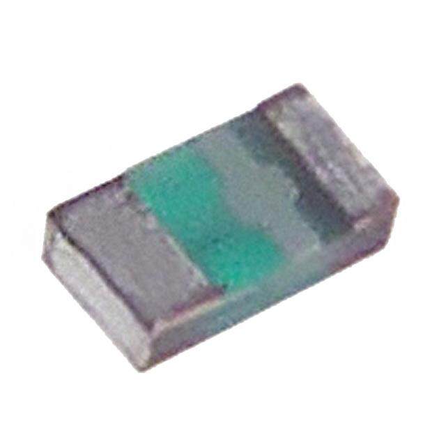
Panasonic Electronic Components的ERB-SD0R50U是一种表面贴装保险丝,主要用于电路中对过电流进行保护。该保险丝具有响应速度快、体积小、可靠性高等特点,适用于对空间和性能都有较高要求的电子设备。

其主要应用场景包括:

1. 消费类电子产品:如智能手机、平板电脑、笔记本电脑、数码相机等,用于保护电源管理电路或充电电路中的过电流故障。

2. 通信设备:在路由器、交换机、基站模块等通信设备中,用于保护敏感的通信接口和供电线路。

3. 工业控制系统:如PLC(可编程逻辑控制器)、工业计算机、传感器模块等,用于保护控制电路或电源模块。

4. 汽车电子系统:如车载导航、娱乐系统、ECU(电子控制单元)等低电压电路中,提供可靠的过流保护。

5. 电源适配器与充电器:用于AC/DC或DC/DC电源转换器中,防止因短路或负载异常导致的损坏。

该保险丝额定电流为0.5A,适用于低电流保护需求的精密电路设计,具备良好的耐久性和稳定性,适合自动化贴装工艺,广泛应用于现代电子产品中。
| 参数 | 数值 |
| 产品目录 | |
| DC冷态电阻 | 0.33 欧姆 |
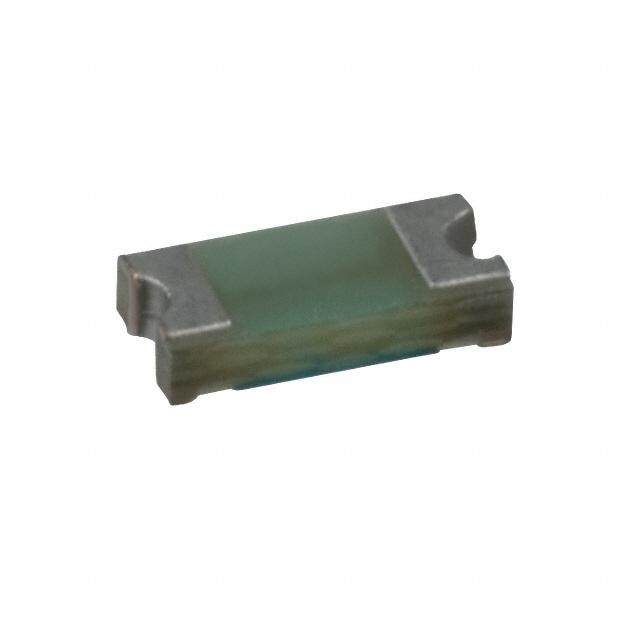
| 描述 | FUSE .5A 24V FAST 0402 SMD |
| 产品分类 | |
| 品牌 | Panasonic Electronic Components |
| 数据手册 | |
| 产品图片 |
|
| 产品型号 | ERB-SD0R50U |
| PCN过时产品 | |
| rohs | 无铅 / 符合限制有害物质指令(RoHS)规范要求 |
| 产品系列 | ERBSD |
| 不同额定电压时的熔断能力 | 35A |
| 产品目录绘图 |
|
| 产品目录页面 | |
| 保险丝类型 | 板安装(不包括管筒式) |
| 其它名称 | P11361DKR |
| 包装 | Digi-Reel® |
| 响应时间 | 快速 |
| 大小/尺寸 | 0.040" 长 x 0.020" 宽 x 0.016" 高(1.00mm x 0.50mm x 0.40mm) |
| 安装类型 | 表面贴装 |
| 封装/外壳 | 0402(1005 公制) |
| 工作温度 | -40°C ~ 100°C |
| 标准包装 | 1 |
| 融断I²t | - |
| 认可 | cUL,UL |
| 颜色 | - |
| 额定电压-AC | - |
| 额定电压-DC | 24V |
| 额定电流 | 500mA |


- 商务部:美国ITC正式对集成电路等产品启动337调查
- 曝三星4nm工艺存在良率问题 高通将骁龙8 Gen1或转产台积电
- 太阳诱电将投资9.5亿元在常州建新厂生产MLCC 预计2023年完工
- 英特尔发布欧洲新工厂建设计划 深化IDM 2.0 战略
- 台积电先进制程称霸业界 有大客户加持明年业绩稳了
- 达到5530亿美元!SIA预计今年全球半导体销售额将创下新高
- 英特尔拟将自动驾驶子公司Mobileye上市 估值或超500亿美元
- 三星加码芯片和SET,合并消费电子和移动部门,撤换高东真等 CEO
- 三星电子宣布重大人事变动 还合并消费电子和移动部门
- 海关总署:前11个月进口集成电路产品价值2.52万亿元 增长14.8%


PDF Datasheet 数据手册内容提取
Micro Chip Fuse Micro Chip Fuse Type: ERBSE ERBSD ■ Features ● Small size ● Fast-acting and withstanding in-rush current characteristics ■ Approved Safety Standards ● UL248-14 : File No.E194052 ● c-UL(CSA)C22.2 No.248-14 : File No.E194052 ■ Explanation of Part Numbers 1 2 3 4 5 6 7 8 9 10 E R B S E 1 R 0 0 U ProductCode FusingCharacteristics Productshape RatedCurrent(A) Packaging Fast-actingand 1608size 0R25 0.25A 1R50 1.5A U Punchedcarriertaping MicroChipFuse S withstandingin-rush E (1.6mm(cid:1)0.8mm) 0R31 0.315A 2R00 2.0A current 1005size 0R37 0.375A 2R50 2.5A D (1.0mm(cid:1)0.5mm) 0R50 0.5A 3R00 3.0A 0R75 0.75A 4R00 4.0A 1R00 1.0A 5R00 5.0A 1R25 1.25A ■Construction ■Dimensions in mm (not to scale) Marking a FusingElement ProtectiveCoating CeramicCore Electrode t (Outer) L W Trimming Type Dimensions (mm) (inches) L W a t ERBSE 1.60±0.15 0.80±0.15 0.30±0.20 0.70 ±0.10 (0603) ERBSD 1.00±0.10 0.50±0.10 0.20±0.15 0.40 ±0.10 (0402) Design and specifi cations are each subject to change without notice. Ask factory for the current technical specifi cations before purchase and/or use. Should a safety concern arise regarding this product, please be sure to contact us immediately. Dec. 2007
Micro Chip Fuse ■ Ratings ● 1608 Size ERBSE(cid:1)R(cid:1)(cid:1)U Part No. 0R50 0R75 1R00 1R25 1R50 2R00 2R50 3R00 4R00 5R00 Rated Current (A) 0.5 0.75 1.0 1.25 1.5 2.0 2.5 3.0 4.0 5.0 Marking Code F G H J K N O P S T Internal R (m(cid:1)) at 25 °C max. 370 245 155 120 90 60 48 36 28 20 Rated Current (cid:2)100 %/4 hours min. Fusing Current/Fusing Time Rated Current (cid:2)200 %/5 seconds max. (at 25 °C) Rated Current (cid:2)300 %/0.2 seconds max. Rated Voltage 32 VDC (Open Circuit Voltage) Interrupting Rating 50 A 35 A (at Rated Voltage) Category Temp. Range −40 °C to +100 °C (Operating Temp. Range) ● 1005 Size ERBSD(cid:1)R(cid:1)(cid:1)U Part No. 0R25 0R31 0R37 0R50 0R75 1R00 1R25 1R50 2R00 2R50 3R00 Rated Current (A) 0.25 0.315 0.375 0.5 0.75 1.0 1.25 1.5 2.0 2.5 3.0 Marking Code V X Y F G H J K N O P Internal R (m(cid:1)) at 25 °C max. 700 570 460 330 200 135 100 80 53 40 33 Rated Current (cid:2)100 %/4 hours min. Fusing Current/Fusing Time Rated Current (cid:2)200 %/5 seconds max. (at 25 °C) Rated Current (cid:2)300 %/0.2 seconds max. Rated Voltage 24 VDC (Open Circuit Voltage) Interrupting Rating 35 A (at Rated Voltage) Category Temp. Range −40 °C to +100 °C (Operating Temp. Range) Power Derating Curve 100 70°C • For Circuit, current rating shall be derated in 80 %) accordance with the fig ure on the right. d( 60 a • This current derating curve is for fusing Lo 40 d characteristics. Rate 20 100°C 0 –40 –20 0 20 40 60 80 100 120 140 AmbientTemperature(°C) Design and specifi cations are each subject to change without notice. Ask factory for the current technical specifi cations before purchase and/or use. Should a safety concern arise regarding this product, please be sure to contact us immediately. Dec. 2007
Micro Chip Fuse ■Fusing Characteristics (25 °C typical) ● I–t Characteristics ●10 TypeERBSE 0.5A 0.75A1.0A1.25A1.5A2.0A2.5A3.0A4.0A5.0A ● Typ10eERBSD 0.25A0.315A0.375A0.5A 0.75A1.0A1.25A1.5A2.0A2.5A3.0A 1 1 (s) (s) me 0.1 me 0.1 Ti Ti g g n n usi 0.01 usi0.01 F F 0.001 0.001 ✽ ReferenceOnly ✽ ReferenceOnly 0.0001 0.0001 0.1 1 10 100 0.1 1 10 100 FusingCurrent(A) FusingCurrent(A) ● I2t–t Characteristics ● TypeERBSE ● TypeERBSD 100 54..00AA 100 3.0A 3.0A 2.5A 2.5A 10 21..05AA 10 21..05AA 1.25A 1.25A 1.0A 1.0A 0.75A 0.75A 1 0.5A 1 0.5A 22t(As)I 0.1 22t(As)I 0.1 000...33271555AAA 0.01 0.01 0.001 0.001 ✽ ReferenceOnly ✽ ReferenceOnly 0.0001 0.0001 0.0001 0.001 0.01 0.1 1 0.0001 0.001 0.01 0.1 1 t(s) t(s) ■ Packaging Methods ● Standard Quantity Type Kind of Taping Pitch (P) Quantity 1 ERBSE 4 mm 5000 pcs./ reel Punched Carrier Taping ERBSD 2 mm 10000 pcs./ reel ● Punched Carrier Taping ● Taping Reel T Sprockethole Compartment φD0 φC E A B FW φ B T Chipcomponent P1 P2 P0 Tapingrunningdirection φA W Type A B W F E φA φB φC W T Dimen Dimensions sions ERBSE 1.00±0.10 1.80±0.20 (mm) ERBSD 0.65±0.05 1.15±0.05 8.00±0.20 3.50±0.05 1.75±0.10 (mm) 180.0−+30.0 60 min. 13.0±1.0 9.0±1.0 11.4±1.0 Type P P P φD T Dimen 1 2 0 0 sions ERBSE 4.00±0.10 0.85±0.07 2.00±0.05 4.00±0.10 1.50+0.10 (mm) ERBSD 2.00±0.10 –0 0.60±0.07 Design and specifi cations are each subject to change without notice. Ask factory for the current technical specifi cations before purchase and/or use. Should a safety concern arise regarding this product, please be sure to contact us immediately. Dec. 2007
Micro Chip Fuse ■ Recommended Land Pattern Dimensions (mm) Type C A B C ERBSE 0.9 2.1 to 2.3 0.8 A ERBSD 0.6 1.4 to 1.6 0.5 B ■ Recommended Soldering Conditions Recommendations and precautions are described below. ●Recommended soldering conditions for reflo w ·Refl ow soldering shall be performed a maximum of two times. For soldering (Example : Sn/Pb) ·Please contact us for additional information when used in conditions other than those specifi ed. Temperature Time ·Please measure the temperature of the terminals and Preheating 140 °C to 160 °C 60 s to 120 s study every kind of solder and printed circuit board Main heating Above 200 °C 30 s to 40 s for solderability before actual use. Peak 235 ± 5 °C max. 10 s Peak For lead-free soldering (Example : Sn/Ag/Cu) ure Preheating Temperature Time erat Preheating 150 °C to 180 °C 60 s to 120 s p m Heating Main heating Above 230 °C 30 s to 40 s e T Peak max. 260 °C max. 10 s Time <Repair with hand soldering> ● Preheat with a blast of hot air or similar method. Use a soldering iron with a tip temperature of 350 °C or less. Solder each electrode for 3 seconds or less. ● Never touch this product with the tip of a soldering iron. Safety Precautions The following are precautions for individual products. Please also refer to the precautions common to EMI Filters, Fuses, and Sensors(MR Elements) shown on page EX2 of this catalog. 1. Set the rated current so that the current passing through the Micro Chip Fuses (hereafter called the fuses) under normal conditions is within 70% of the rated current. 2. Do not continuously pass a current exceeding the rated current through the fuses. 3. If a pulse exceeding the rated current is applied, such as a rush current or surge current at power-on, take care not to cause unwanted fusing. Calculate the I2t value of the pulse and check the tolerance to the number of pulses according to the I2t-t characteristic curve before deciding to use the fuses. Before checking the tolerance, consult our sales staff in advance. 4. The fuses are designed to be blown out by a current that is double or greater than the rated current. Ensure that the abnormal current generated when a circuit abnormality occurs in your product is at least double or greater than the rated current of the fuses. In addition, ensure that the abnormal curr ent of your product does not exceed the maximum interrupting current of the fuses. 5. The fuses are designed to be used on the secondary side of a power supply. Do not use them on the primary side. 6. Ensure that the voltage applied to the fuses are within their rated voltage. 7. The fusing characteristics of the fuses are affected by the ambient temperature. Before use, mount the fuses on your products and carefully check and evaluate their operating temperature range. Design and specifi cations are each subject to change without notice. Ask factory for the current technical specifi cations before purchase and/or use. Should a safety concern arise regarding this product, please be sure to contact us immediately. Feb. 2006
Safety Precautions (Common precautions for EMI Filters, Fuses, and Sensors[MR Elements]) (cid:127) When using our products, no matter what sort of equipment they might be used for, be sure to make a written agreement on the specific ations with us in advance. The design and specifi cations in this catalog are subject to change without prior notice. (cid:127) Do not use the products beyond the specific ations described in this catalog. (cid:127) This catalog explains the quality and performance of the products as individual components. Before use, check and evaluate their operations when installed in your products. (cid:127) Install the following systems for a failsafe design to ensure safety if these products are to be used in equip ment where a defect in these products may cause the loss of human life or other signific ant dam age, such as damage to vehicles (automobile, train, vessel), traffic lights, medical equipment, aerospace equipment, electric heating appliances, combustion/gas equipment, rotating equipment, and disaster/crime prevention equipment. ✽Systems equipped with a protection circuit and a protection device ✽Systems equipped with a redundant circuit or other system to prevent an unsafe status in the event of a sing le fault (1) Precautions for use (cid:127) These products are designed and manufactured for general and standard use in general elect roni c equipment (e.g. AV equipment, home electric appliances, offic e equipment, information and communication equipment) (cid:127) These products are not intended for use in the following special conditions. Before using the products, carefully check the effects on their quality and performance, and determine whether or not they can be used. 1. In liquid, such as water, oil, chemicals, or organic solvent 2. In direct sunlight, outdoors, or in dust 3. In salty air or air with a high concentration of corrosive gas, such as Cl, H S, NH , SO , or NO 2 2 3 2 2 4. Electric Static Discharge (ESD) Environment These components are sensitive to static electricity and can be damaged under static shock (ESD). Please take measures to avoid any of these environments. Smaller components are more sensitive to ESD environment. 5. Electromagnetic Environment Avoid any environment where strong electromagnetic waves exist. 6. In an environment where these products cause dew condensation 7. Sealing or coating of these products or a printed circuit board on which these products are mounted, with resin or other materials (cid:127) These products generate Joule heat when energized. Carefully position these products so that their heat will not affect the other components. (cid:127) Carefully position these products so that their temperatures will not exceed the category temperature range due to the effects of neighboring heat-generating components. Do not mount or place heat-generating components or infl ammables, such as vinyl-coated wires, near these products (except Thermal Cutoffs). (cid:127) Note that non-cleaning solder, halogen-based highly active fl ux, or water-soluble fl ux may deteriorate the performance or reliability of the products. (cid:127) Carefully select a fl ux cleaning agent for use after soldering. An unsuitable agent may deteriorate the performance or reliability. In particular, when using water or a water-soluble cleaning agent, be careful not to leave water residues. Otherwise, the insulation performance may be deteriorated. (2) Precautions for storage The performance of these products, including the solderability, is guaranteed for a year from the date of arr iva l at your company, provided that they remain packed as they were when delivered and stored at a tem pera ture of 5 °C to 35 °C and a relative humidity of 45 % to 85 %. (Micro Chip Fuses: Guaranteed for 6 months from the date of arrival at your company) The performance of EMI Filters is guaranteed for 6 months or a year from the out goi ng inspection date indicated on the packages, provided that they are stored at a temperature of -5 °C to +40 °C and a relative humidity of 40 % to 60 %. Check the guarantee period in the specifi cations. The performance of Thermal Cut offs is guaranteed for a year from the outgoing inspection date indicated on the packages, provided that they are stored at a temperature of -10 °C to +40 °C and a relative humidity of 30 % to 75 %. Even within the above guarantee periods, do not store these products in the following conditions. Otherwise, their electrical performance and/or solderability may be deteriorated, and the packaging materials (e.g. taping materials) may be deformed or deteriorated, resulting in mounting failures. 1. In salty air or in air with a high concentration of corrosive gas, such as Cl, H S, NH , SO , or NO 2 2 3 2 2 2. In direct sunlight <Package markings> Package markings include the product number, quantity, and country of origin. In principle, the country of origin should be indicated in English. Feb. 2006 – EX2 –