ICGOO在线商城 > 电阻器 > 芯片电阻 - 表面安装 > ERA-3ARB333V
 Datasheet下载
- 型号: ERA-3ARB333V
- 制造商: Panasonic Corporation
- 库位|库存: xxxx|xxxx
- 要求:
| 数量阶梯 | 香港交货 | 国内含税 |
| +xxxx | $xxxx | ¥xxxx |
查看当月历史价格
查看今年历史价格
ERA-3ARB333V产品简介:
ICGOO电子元器件商城为您提供ERA-3ARB333V由Panasonic Corporation设计生产,在icgoo商城现货销售,并且可以通过原厂、代理商等渠道进行代购。 ERA-3ARB333V价格参考。Panasonic CorporationERA-3ARB333V封装/规格:芯片电阻 - 表面安装, 33 kOhms ±0.1% 0.1W, 1/10W Chip Resistor 0603 (1608 Metric) Automotive AEC-Q200 Thin Film。您可以下载ERA-3ARB333V参考资料、Datasheet数据手册功能说明书,资料中有ERA-3ARB333V 详细功能的应用电路图电压和使用方法及教程。
Panasonic Electronic Components 旗下的 ERA-3ARB333V 是一款芯片电阻(表面贴装型),阻值为33.3kΩ,精度±0.1%,功率1/4W,尺寸为0603(1608公制),具有高精度、低温漂(5ppm/℃)特性。该型号广泛应用于对稳定性与精度要求较高的电子设备中。

典型应用场景包括:精密测量仪器,如数字万用表、示波器中的分压电路和反馈回路;工业控制设备中的传感器信号调理电路,确保微弱信号的准确采集;医疗电子设备,如心电图机、监护仪等,保障信号处理的可靠性;通信设备中的模拟前端,用于阻抗匹配与信号滤波;高端消费类电子产品,如高保真音频设备中的偏置与增益控制电路。

由于其优异的长期稳定性和低温度系数,ERA-3ARB333V 特别适用于环境温度变化较大或需长时间连续运行的场合。此外,在电源管理模块、ADC/DAC 转换电路中也常被采用,以提升系统整体精度与可靠性。该电阻符合AEC-Q200车规标准,因此也可用于汽车电子系统,如车载传感器、电池管理系统(BMS)等。

综上,ERA-3ARB333V 凭借高精度、高稳定性,广泛服务于工业、医疗、通信、汽车电子及高端消费电子等领域,是精密电路设计中的关键元件。
| 参数 | 数值 |
| 产品目录 | |
| 描述 | RES 33K OHM 1/10W .1% 0603 SMD |
| 产品分类 | |
| 品牌 | Panasonic Electronic Components |
| 数据手册 | http://industrial.panasonic.com/www-cgi/jvcr13pz.cgi?E+PZ+4+AOA0026+ERA3ARB333V+8+WW |
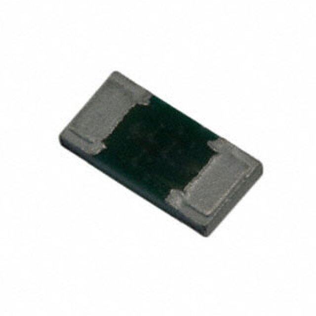
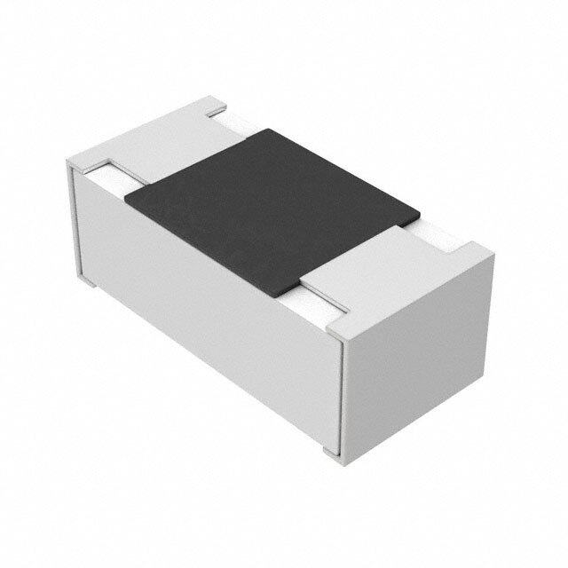
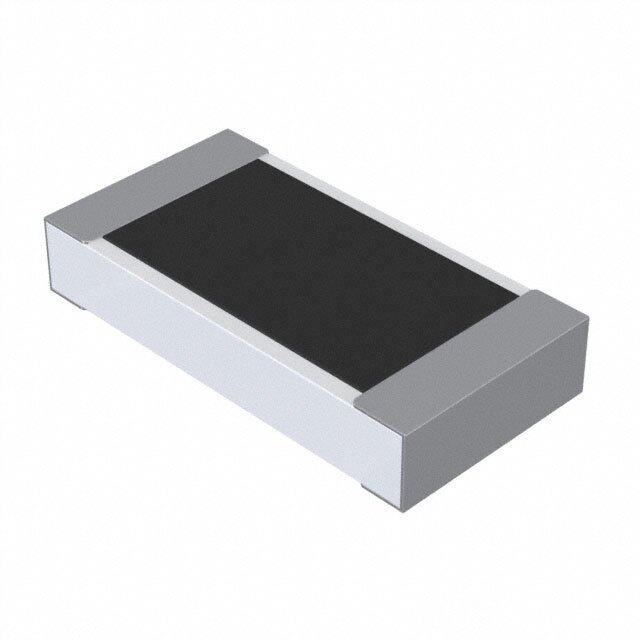
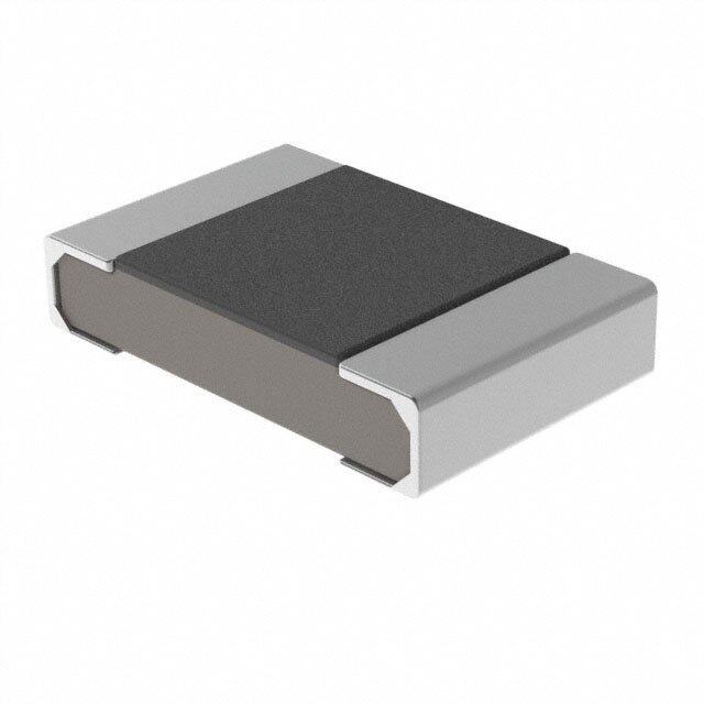
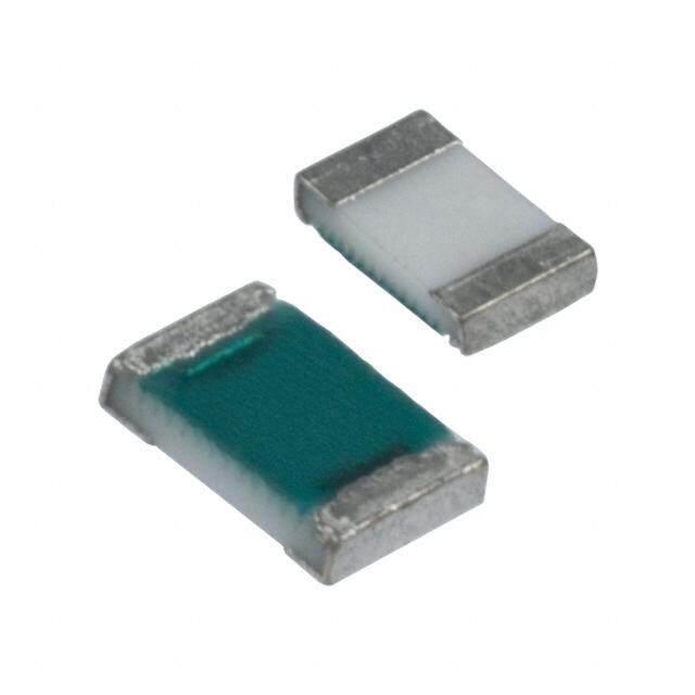
| 产品图片 |
|
| 产品型号 | ERA-3ARB333V |
| rohs | 无铅 / 符合限制有害物质指令(RoHS)规范要求 |
| 产品系列 | ERA-3A |
| 供应商器件封装 | 0603 |
| 其它名称 | P33KBDDKR |
| 功率(W) | 0.1W,1/10W |
| 包装 | Digi-Reel® |
| 大小/尺寸 | 0.063" 长 x 0.031" 宽(1.60mm x 0.80mm) |
| 容差 | ±0.1% |
| 封装/外壳 | 0603(1608 公制) |
| 成分 | |
| 标准包装 | 1 |
| 温度系数 | ±10ppm/°C |
| 特性 | 获得 AEC-Q200 汽车认证 |
| 电阻(Ω) | 33k |
| 端子数 | 2 |
| 高度 | 0.022"(0.55mm) |


PDF Datasheet 数据手册内容提取
Metal Film (Thin Film) Chip Resistors, High Reliability Type Metal Film (Thin Film) Chip Resistors, High Reliability Type Type: ERA 1A, 2A, 3A, 6A, 8A Features ● High reliability ................Stable at high temperature and humidity (85 °C 85 %RH rated load, Category temperature range : –55 °C to +155 °C) ● High accuracy ...............Small resistance tolerance and Temperature Coeffi cient of Resistance ● High performance .........Low current noise, excellent linearity ● Reference Standard ......IEC 60115-8, JIS C 5201-8, EIAJ RC-2133B ● AEC-Q200 qualifi ed ● RoHS compliant ■ As for Packaging Methods, Land Pattern, Soldering Conditions and Safety Precautions, Please see Data Files Explanation of Part Numbers ● E24 Series 1 2 3 4 5 6 7 8 9 10 11 E R A 3 A E B 1 0 2 V Product Code Size, Power Rating Temperature Coefficient Resistance Tolerance Packaging Methods Metal Film Code Inch Power Rating Code T.C.R. Code Tolerance Code Packaging Part No. Chip Resistors 1A 0201 0.05 W R ±10×10–6/°C W ±0.05 % C Pressed Carrier Taping ERA1A 2A 0402 0.063 W P ±15×10–6/°C B ±0.1 % 2 mm pitch, 15000 pcs. 3A 0603 0.1 W E ±25×10–6/°C C ±0.25 % X Punched Carrier Taping ERA2A 2 mm pitch, 10000 pcs. 6A 0805 0.125 W H ±50×10–6/°C D ±0.5 % ERA3A 8A 1206 0.25 W K ±100×10–6/°C V Punched CarrierTaping ERA6A 4 mm pitch, 5000 pcs. ERA8A Resistance Value Consist of three figures for E24 series resistance value. The first two digits are significant figures of resistance and the third one denotes number of zeros following. (example) 102 : 1k Ω ● E96 Series and other Resistance values 1 2 3 4 5 6 7 8 9 10 11 12 E R A 3 A E B 1 0 5 1 V Product Code Size, Power Rating Temperature Coefficient Resistance Tolerance Packaging Methods Metal Film Code Inch Power Rating Code T.C.R. Code Tolerance Code Packaging Part No. Chip Resistors 1A 0201 0.05 W R ±10×10–6/°C W ±0.05 % C Pressed Carrier Taping ERA1A 2A 0402 0.063 W P ±15×10–6/°C B ±0.1 % 2 mm pitch, 15000 pcs. 3A 0603 0.1 W E ±25×10–6/°C C ±0.25 % X Punched Carrier Taping ERA2A 2 mm pitch, 10000 pcs. 6A 0805 0.125 W H ±50×10–6/°C D ±0.5 % ERA3A 8A 1206 0.25 W K ±100×10–6/°C V Punched CarrierTaping ERA6A 4 mm pitch, 5000 pcs. ERA8A Resistance Value Consist of four figures for E96 series resistance value. The first three digits are significant figures of resistance and the fourth one denotes number of zeros following. (example) 1051 : 1.05k Ω note : Duplicated resistance values as E24 series part numbers shall follow E24 part numbers. (apply three digit resistance value) Design and specifications are each subject to change without notice. Ask factory for the current technical specifications before purchase and/or use. Should a safety concern arise regarding this product, please be sure to contact us immediately. 12 Sep. 2018
Metal Film (Thin Film) Chip Resistors, High Reliability Type Construction Dimensions in mm (not to scale) L Protective coating a Electrode (Inner) Alumina substrate W t Electrode b (Between) Part No. Dimensions (mm) Mass (Weight) (inch size) L W a b t [g/1000 pcs.] ERA1A (0201) 0.60±0.03 0.30±0.03 0.15±0.05 0.15±0.05 0.23±0.03 0.14 ERA2A (0402) 1.00±0.10 0.50+–00..1005 0.15±0.10 0.25±0.10 0.35±0.05 0.6 High reliability ERA3A (0603) 1.60±0.20 0.80±0.20 0.30±0.20 0.30±0.20 0.45±0.10 2 Electrode (Outer) metal film ERA6A (0805) 2.00±0.20 1.25±0.10 0.40±0.25 0.40±0.25 0.50±0.10 4 ERA8A (1206) 3.20±0.20 1.60+–00..1055 0.50±0.25 0.50±0.25 0.60±0.10 8 Ratings Power Rating Limiting Element Maximum Resistance Resistance Category Part No. Part No. T.C.R. at 85 °C Voltage(1) Overload Voltage(2) Tolerance Range(3)(4) Temperature Range (inch size) (detail) (×10–6/°C) (W) (V) (V) (%) (Ω) (°C) ERA1AEB ±0.1 ±25 100 to 10k (E24, E96) ERA1AEC ±0.25 ERA1A 0.05 25 50 ERA1ARC ±0.25 (0201) 100 to 10k (E24, E96) ERA1ARB ±0.1 ±10 ERA1ARW ±0.05 1k to 10k (E24, E96) ERA2AKD ±0.5 ±100 10 to 46.4 (E24, E96) ERA2AED ±0.5 ERA2AEC ±0.25 ±25 47 to 100k (E24, E96) ERA2A ERA2AEB ±0.1 0.063 50 100 (0402) ERA2APC ±0.25 ±15 200 to 47k (E24, E96) ERA2APB ±0.1 ERA2ARC ±0.25 ±10 200 to 47k (E24, E96) ERA2ARB ±0.1 ERA3AHD ±0.5 ±50 10 to 46.4 (E24, E96) ERA3AED ±0.5 ERA3AEC ±0.25 ±25 47 to 330k (E24, E96) ERA3AEB ±0.1 ERA3A 0.1 75 150 ERA3APC ±0.25 (0603) ±15 470 to 100k (E24, E96) ERA3APB ±0.1 ERA3ARC ±0.25 –55 to +155 ERA3ARB ±0.1 ±10 1k to 100k (E24, E96) ERA3ARW ±0.05 ERA6AHD ±0.5 ±50 10 to 46.4 (E24, E96) ERA6AED ±0.5 ERA6AEC ±0.25 ±25 47 to 1M (E24, E96) ERA6AEB ±0.1 ERA6A 0.125 100 200 ERA6APC ±0.25 (0805) ±15 470 to 100k (E24, E96) ERA6APB ±0.1 ERA6ARC ±0.25 ERA6ARB ±0.1 ±10 1k to 100k (E24, E96) ERA6ARW ±0.05 ERA8AHD ±0.5 ±50 10 to 46.4 (E24, E96) ERA8AED ±0.5 ERA8AEC ±0.25 ±25 47 to 1M (E24, E96) ERA8AEB ±0.1 ERA8A 0.25 150 300 ERA8APC ±0.25 (1206) ±15 470 to 100k (E24, E96) ERA8APB ±0.1 ERA8ARC ±0.25 ERA8ARB ±0.1 ±10 1k to 100k (E24, E96) ERA8ARW ±0.05 (1) Rated Continuous Working Voltage (RCWV) shall be det er mined from RCWV=√Rated Power × Re sis tance Values, or Limiting Element Voltage liste d above, whichever less. (2) Overload (Short-time Overload) Test Voltage (SOTV) shall be det ermined from SOTV=2.5 × RCWV or max. Overl oad Volt age list ed above which ev er less. (3) E192 series resistance values are also available. Please contact us for details. (4) Duplicated resistance values between E96, E192 and E24 series shall follow E24 Part Numbers. (apply three digit resistance value) Design and specifications are each subject to change without notice. Ask factory for the current technical specifications before purchase and/or use. Should a safety concern arise regarding this product, please be sure to contact us immediately. 12 Sep. 2018
Metal Film (Thin Film) Chip Resistors, High Reliability Type Power Derating Curve –55 °C 85 °C 100 For resistors operated in ambient temperatures above 8w5it h° Cth,e pfiogwuerer orant itnhge rsighahltl. be derated in accordance ad (%) 6800 o d L 40 e at 20 R 155 °C 0 –60 –40 –20 0 20 40 60 80 100 120 140 160 180 Ambient Temperature (°C) Design and specifications are each subject to change without notice. Ask factory for the current technical specifications before purchase and/or use. Should a safety concern arise regarding this product, please be sure to contact us immediately. 12 Sep. 2018
Surface Mount Resistors Safety precautions Safety Precautions (Common precautions for Surface Mount Resistors) The following are precautions for individual products. Please also refer to the common precautions for Fixed Resistors in this catalog. 1. Take measures against mechanical stress during and after mounting of Surface Mount Resistors (hereafter called the resistors) so as not to damage their electrodes and protective coatings. Be careful not to misplace the resistors on the land patterns. Otherwise, solder bridging may occur. 2. Keep the rated power and ambient temperature within the specified derating curve. Some circuit boards, wiring patterns, temperatures of heat generated by adjacent components, or amb ie nt tem per a tures can become factors in the rise of the temperature of the res is tors, regardless of the level of power applied. Therefore, check the conditions before use and op ti mize them so as not to damage the boards and peripheral components. Make sure to contact us before using the resistors under special conditions. 3. If a transient load (heavy load in a short time) like a pulse is expected to be applied, check and evaluate the operations of the resistors when installed in your products before use. Never exceed the rated power. Otherwise, the performance and/or reliability of the resistors may be impaired. 4. Before using halogen-based or other high-activity flux, check the possible effects of the flux residues on the per for mance and reliability of the resistors. 5. When soldering with a soldering iron, never touch the resistors'bodies with the tip of the soldering iron. When using a soldering iron with a high temperature tip, finish soldering as quickly as possible (within three seconds at 350 °C max.). 6. As the amount of applied solder becomes larger, the mechanical stress applied to the resistors increases, causing problems such as cracks and faulty characteristics. Avoid applying an excessive amounts of solder. 7. When the resistors' protective coatings are chipped, flawed, or removed, the characteristics of the resistors may be impaired. Take special care not to apply mechanical shock during automatic mounting or cause damage during handling of the boards with the resistors mounted. 8. Do not apply shock to the resistors or pinch them with a hard tool (e.g. pliers and tweezers). Otherwise, the resistors' protective coatings and bodies may be chipped, affecting their performance. 9. Avoid excessive bending of printed circuit boards in order to protect the resistors from abnormal stress. 10. Do not immerse the resistors in solvent for a long time. Before using solvent, carefully check the effects of imm er sion. 11. Transient voltage If there is a possibility that the transient phen om e non (significantly high voltage ap plied in a short time) may occ ur or that a high voltage pulse may be applied, make sure to evaluate and check the chara ct er is tics of Fixed Metal (Oxide) Film Resistors mounted on your product rather than only depending on the calculated pow er limit or steady-state conditions to complete the des ign or decide to use the resistors. 12. Do not apply excessive tension to the terminals. Design and specifications are each subject to change without notice. Ask factory for the current technical specifications before purchase and/or use. Should a safety concern arise regarding this product, please be sure to contact us immediately. 02 Sep. 2014
Safety Precautions (Common precautions for Fixed Resistors) • When using our products, no matter what sort of equipment they might be used for, be sure to make a written agreement on the specifications with us in advance. The design and specifications in this catalog are subject to change without prior notice. • Do not use the products beyond the specifications described in this catalog. • This catalog explains the quality and performance of the products as individual components. Before use, check and evaluate their operations when installed in your products. • Install the following systems for a failsafe design to ensure safety if these products are to be used in equipm ent where a defect in these products may cause the loss of human life or other significant dam age, such as damage to vehicles (automobile, train, vessel), traffic lights, medical equipment, aerospace equipment, electric heating appliances, combustion/gas equipment, rotating equipment, and disaster/crime prevention equipment. ✽ Systems equipped with a protection circuit and a protection device ✽ Systems equipped with a redundant circuit or other system to prevent an unsafe status in the event of a sing le fault (1) Precautions for use • These products are designed and manufactured for general and standard use in general elect ron ic equipment (e.g. AV equipment, home electric appliances, office equipment, information and communication equipment) • These products are not intended for use in the following special conditions. Before using the products, carefully check the effects on their quality and performance, and determine whether or not they can be used. 1. In liquid, such as water, oil, chemicals, or organic solvent 2. In direct sunlight, outdoors, or in dust 3. In salty air or air with a high concentration of corrosive gas, such as Cl, H S, NH , SO , or NO 2 2 3 2 2 4. Electric Static Discharge (ESD) Environment These components are sensitive to static electricity and can be damaged under static shock (ESD). Please take measures to avoid any of these environments. Smaller components are more sensitive to ESD environment. 5. Electromagnetic Environment Avoid any environment where strong electromagnetic waves exist. 6. In an environment where these products cause dew condensation 7. Sealing or coating of these products or a printed circuit board on which these products are mounted, with resin or other materials • These products generate Joule heat when energized. Carefully position these products so that their heat will not affect the other components. • Carefully position these products so that their temperatures will not exceed the category temperature range due to the effects of neighboring heat-generating components. Do not mount or place heat-generating components or inflammables, such as vinyl-coated wires, near these products. • Note that non-cleaning solder, halogen-based highly active flux, or water-soluble flux may deteriorate the performance or reliability of the products. • Carefully select a flux cleaning agent for use after soldering. An unsuitable agent may deteriorate the performance or reliability. In particular, when using water or a water-soluble cleaning agent, be careful not to leave water residues. Otherwise, the insulation performance may be deteriorated. (2) Precautions for storage The performance of these products, including the solderability, is guaranteed for a year from the date of arr iv al at your company, provided that they remain packed as they were when delivered and stored at a temp er a ture of 5 °C to 35 °C and a relative humidity of 45 % to 85 %. Even within the above guarantee periods, do not store these products in the following conditions. Otherwise, their electrical performance and/or solderability may be deteriorated, and the packaging materials (e.g. taping materials) may be deformed or deteriorated, resulting in mounting failures. 1. In salty air or in air with a high concentration of corrosive gas, such as Cl, H S, NH , SO , or NO 2 2 3 2 2 2. In direct sunlight <Package markings> Package markings include the product number, quantity, and country of origin. In principle, the country of origin should be indicated in English. 01 Sep. 2014
Mouser Electronics Authorized Distributor Click to View Pricing, Inventory, Delivery & Lifecycle Information: P anasonic: ERA-6AEB105V ERA-6AEB5763V ERA-2AED101X ERA-2AED102X ERA-2AED103X ERA-2AED104X ERA- 2AED111X ERA-2AED112X ERA-2AED113X ERA-2AED121X ERA-2AED122X ERA-2AED123X ERA-2AED131X ERA-2AED132X ERA-2AED133X ERA-2AED151X ERA-2AED152X ERA-2AED153X ERA-2AED161X ERA- 2AED162X ERA-2AED163X ERA-2AED181X ERA-2AED182X ERA-2AED183X ERA-2AED201X ERA-2AED202X ERA-2AED203X ERA-2AED221X ERA-2AED222X ERA-2AED223X ERA-2AED241X ERA-2AED242X ERA- 2AED243X ERA-2AED271X ERA-2AED272X ERA-2AED273X ERA-2AED301X ERA-2AED302X ERA-2AED303X ERA-2AED331X ERA-2AED332X ERA-2AED333X ERA-2AED361X ERA-2AED362X ERA-2AED363X ERA- 2AED391X ERA-2AED392X ERA-2AED393X ERA-2AED431X ERA-2AED432X ERA-2AED433X ERA-2AED470X ERA-2AED471X ERA-2AED472X ERA-2AED473X ERA-2AED510X ERA-2AED511X ERA-2AED512X ERA- 2AED513X ERA-2AED560X ERA-2AED561X ERA-2AED562X ERA-2AED563X ERA-2AED620X ERA-2AED621X ERA-2AED622X ERA-2AED623X ERA-2AED680X ERA-2AED681X ERA-2AED682X ERA-2AED683X ERA- 2AED750X ERA-2AED751X ERA-2AED752X ERA-2AED753X ERA-2AED820X ERA-2AED821X ERA-2AED822X ERA-2AED823X ERA-2AED910X ERA-2AED911X ERA-2AED912X ERA-2AED913X ERA-2AKD100X ERA- 2AKD110X ERA-2AKD120X ERA-2AKD130X ERA-2AKD150X ERA-2AKD160X ERA-2AKD180X ERA-2AKD200X ERA-2AKD220X ERA-2AKD240X ERA-2AKD270X ERA-2AKD300X ERA-2AKD330X ERA-2AKD360X ERA- 2AKD390X ERA-2AKD430X ERA-3AEB111V