 Datasheet下载
- 型号: EGG.00.302.CLL
- 制造商: LEMO
- 库位|库存: xxxx|xxxx
- 要求:
| 数量阶梯 | 香港交货 | 国内含税 |
| +xxxx | $xxxx | ¥xxxx |
查看当月历史价格
查看今年历史价格
EGG.00.302.CLL产品简介:
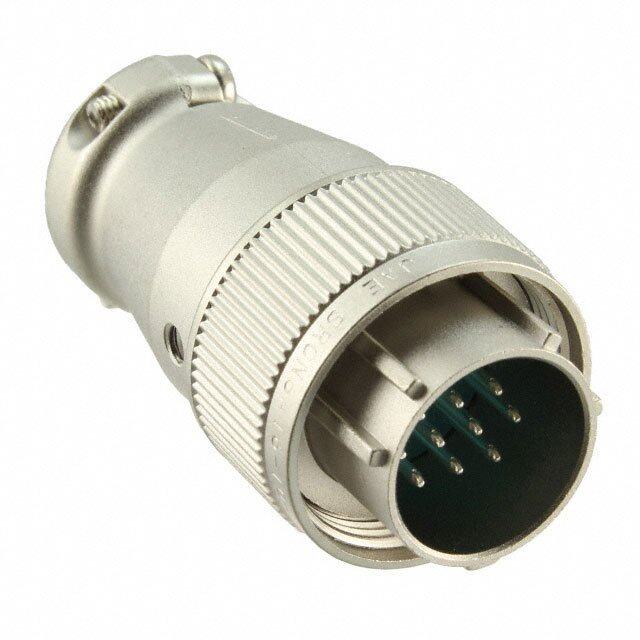
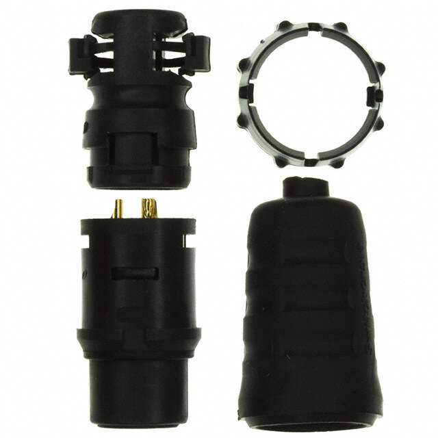
ICGOO电子元器件商城为您提供EGG.00.302.CLL由LEMO设计生产,在icgoo商城现货销售,并且可以通过原厂、代理商等渠道进行代购。 EGG.00.302.CLL价格参考¥93.28-¥129.16。LEMOEGG.00.302.CLL封装/规格:圆形连接器, 2 位置 圆形连接器 插座,母形插口 焊杯 金。您可以下载EGG.00.302.CLL参考资料、Datasheet数据手册功能说明书,资料中有EGG.00.302.CLL 详细功能的应用电路图电压和使用方法及教程。
LEMO品牌型号为EGG.00.302.CLL的圆形连接器,属于R系列高可靠性推拉式锁定连接器。其主要应用场景如下:

1. 医疗设备:该连接器广泛应用于医疗成像设备(如CT、MRI)、超声设备、手术机器人以及监护仪等。它支持快速插拔,确保信号传输稳定可靠,并能满足医疗环境对无菌和清洁的要求。

2. 工业自动化:在工业控制领域,这种连接器用于数据采集系统、传感器接口、机器人控制器和工业相机等。其坚固耐用的设计适合复杂的工业环境,能够承受振动和冲击。

3. 航空航天与国防:由于其高可靠性及抗恶劣环境的能力,EGG.00.302.CLL适用于卫星通信、无人机、导弹制导系统以及机载电子设备中。它支持多种信号类型(如射频、光纤、电源和高速数字信号)的传输。

4. 测试与测量:在实验室或现场测试设备中,该型号被用来连接示波器、信号发生器、频谱分析仪等仪器。其优异的电气性能和机械性能保证了测试结果的精确性。

5. 广播与影音设备:此连接器也常见于高清摄像机、视频切换台和舞台灯光控制系统中,提供稳定的音频、视频和数据传输。

6. 交通运输:包括轨道交通(高铁、地铁)和汽车电子(自动驾驶、车载娱乐系统),这些场景需要连接器具备防尘、防水和耐高温特性,而LEMO R系列正好满足这些需求。

总之,EGG.00.302.CLL凭借其紧凑设计、多样化接触配置(如同轴、光纤、电力等)以及卓越的环境适应能力,在众多高科技领域中发挥重要作用。
| 参数 | 数值 |
| 产品目录 | |
| 描述 | CONN PNL MNT RCPT 2SKT SLD CUP环形推拉式连接器 RECP SIZE 00 2-PIN FEMALE SLDR |
| 产品分类 | |
| 品牌 | LEMO |
| 产品手册 | |
| 产品图片 |
|
| rohs | 符合RoHS无铅 / 符合限制有害物质指令(RoHS)规范要求 |
| 产品系列 | 环形推拉式连接器,LEMO EGG.00.302.CLL0 |
| 数据手册 | |
| 产品型号 | EGG.00.302.CLL |
| 产品种类 | 环形推拉式连接器 |
| 产品类型 | Connectors |
| 侵入防护 | IP50 - 防尘 |
| 其它名称 | 1124-1334 |
| 包装 | 散装 |
| 商标 | LEMO |
| 外壳尺寸-插件 | 302 |
| 外壳尺寸,MIL | - |
| 外壳材料,镀层 | 黄铜,镀铬 |
| 外壳电镀 | Chrome |
| 外壳类型 | Receptacle |
| 安装类型 | 面板安装,隔墙式(后端螺母) |
| 安装风格 | Cable |
| 工作温度 | -55°C ~ 250°C |
| 工厂包装数量 | 75 |
| 朝向 | G |
| 标准包装 | 1 |
| 特性 | 屏蔽 |
| 电压-额定 | - |
| 电流额定值 | 5 A |
| 相关产品 | /product-detail/zh/BRE.00.200.KAS/BRE.00.200.KAS-ND/3791048/product-detail/zh/BRA.00.200.PCSG/1124-1003-ND/2786105/product-detail/zh/BRE.00.200.NAS/BRE.00.200.NAS-ND/3687836/product-detail/zh/BRA.00.200.PCSN/BRA.00.200.PCSN-ND/3791033/product-detail/zh/GBA.00.250.FN/GBA.00.250.FN-ND/3803952/product-detail/zh/GCA.00.255.LT/GCA.00.255.LT-ND/3803966/product-detail/zh/GEA.00.240.LN/GEA.00.240.LN-ND/3804039/product-detail/zh/GRA.00.269.GA/GRA.00.269.GA-ND/3804349/product-detail/zh/GRA.00.269.GB/GRA.00.269.GB-ND/3804350/product-detail/zh/GRA.00.269.GG/GRA.00.269.GG-ND/3804351/product-detail/zh/GRA.00.269.GJ/GRA.00.269.GJ-ND/3804352/product-detail/zh/GRA.00.269.GM/GRA.00.269.GM-ND/3804353/product-detail/zh/GRA.00.269.GN/GRA.00.269.GN-ND/3804354/product-detail/zh/GRA.00.269.GR/GRA.00.269.GR-ND/3804355/product-detail/zh/GRA.00.269.GS/GRA.00.269.GS-ND/3804356/product-detail/zh/GRA.00.269.GV/GRA.00.269.GV-ND/3804357 |
| 端接 | 焊杯 |
| 端接类型 | Solder |
| 系列 | 00 |
| 紧固类型 | 推挽式 |
| 触头镀层 | 金 |
| 触头镀层厚度 | - |
| 触点数量 | 2 |
| 触点电镀 | Copper, Nickel, Gold |
| 触点类型 | Socket (Female) |
| 连接器类型 | 插座,母形插口 |
| 配套产品 | /product-detail/zh/FHG.00.302.CLAD17/FHG.00.302.CLAD17-ND/3802194/product-detail/zh/FGG.00.302.CLAD35Z/1124-1014-ND/2786116/product-detail/zh/FGG.00.302.CLAD35/FGG.00.302.CLAD35-ND/3797467/product-detail/zh/FGG.00.302.CLAD22Z/FGG.00.302.CLAD22Z-ND/3689323/product-detail/zh/FGG.00.302.CLAD27/FGG.00.302.CLAD27-ND/3689324/product-detail/zh/FGG.00.302.CLAD27Z/FGG.00.302.CLAD27Z-ND/3689325/product-detail/zh/FGG.00.302.CLAD30/FGG.00.302.CLAD30-ND/3689326/product-detail/zh/FGG.00.302.CLAD30Z/FGG.00.302.CLAD30Z-ND/3689327/product-detail/zh/FGG.00.302.CYCD35Z/FGG.00.302.CYCD35Z-ND/3689329/product-detail/zh/FHG.00.302.CLAD35/FHG.00.302.CLAD35-ND/3690162/product-detail/zh/FHG.00.302.CLAD35Z/FHG.00.302.CLAD35Z-ND/3690163/product-detail/zh/FGG.00.302.CYCD27/FGG.00.302.CYCD27-ND/3797469/product-detail/zh/FGG.00.302.CYCD35/FGG.00.302.CYCD35-ND/3797470/product-detail/zh/FGG.00.302.CLAD17/FGG.00.302.CLAD17-ND/3797464/product-detail/zh/FGG.00.302.CLAD17Z/FGG.00.302.CLAD17Z-ND/3797465/product-detail/zh/FGG.00.302.CLAD22/FGG.00.302.CLAD22-ND/3797466/product-detail/zh/FHG.00.302.CLAD22/FHG.00.302.CLAD22-ND/3802195/product-detail/zh/FHG.00.302.CLAD22Z/FHG.00.302.CLAD22Z-ND/3802196/product-detail/zh/FHG.00.302.CLAD27/FHG.00.302.CLAD27-ND/3802197/product-detail/zh/FHG.00.302.CLAD27Z/FHG.00.302.CLAD27Z-ND/3802198/product-detail/zh/FHG.00.302.CLAD30/FHG.00.302.CLAD30-ND/3802199/product-detail/zh/FHG.00.302.CLAD30Z/FHG.00.302.CLAD30Z-ND/3802200 |
| 针脚数 | 2 |
| 额定电流 | 5A |


- 商务部:美国ITC正式对集成电路等产品启动337调查
- 曝三星4nm工艺存在良率问题 高通将骁龙8 Gen1或转产台积电
- 太阳诱电将投资9.5亿元在常州建新厂生产MLCC 预计2023年完工
- 英特尔发布欧洲新工厂建设计划 深化IDM 2.0 战略
- 台积电先进制程称霸业界 有大客户加持明年业绩稳了
- 达到5530亿美元!SIA预计今年全球半导体销售额将创下新高
- 英特尔拟将自动驾驶子公司Mobileye上市 估值或超500亿美元
- 三星加码芯片和SET,合并消费电子和移动部门,撤换高东真等 CEO
- 三星电子宣布重大人事变动 还合并消费电子和移动部门
- 海关总署:前11个月进口集成电路产品价值2.52万亿元 增长14.8%
.jpg)
PDF Datasheet 数据手册内容提取
00 NIM-CAMAC & 01 COAXIAL CONNECTORS
None
® ® LEMO coaxial 00 and 01 Series (50Ω) Fundamental research in particle physics as practised within CERN and other nuclear research establishments requires more and more complex equipment of high performance in order to achieve the objectives. The needs of such research contribute to the development of leading products for the whole of industry. For many years LEMO has participated in this evolution. This has resulted in a range of miniature coaxial connectors (50 Ω) with a push-pull self-latching system, the LEMO 00.250 series. These connectors now form the basis of the NIM-CAMAC CD/N 549 standard. The plugs and sockets of the 01 series are amongst the smallest available 50 Ω coaxial connectors with a self-latching intermating capability. In spite of their small size and light weight, their technical characteristics remain excellent. Avail- able in a wide range of housing configurations, they are especially useful when connecting onto printed circuit boards. The LEMO 00 series and 01 are now used in many areas such as: telecommunications, sensors, medical equipment, space research, etc... The program covered in this catalog now includes more than 50 models suitable for many cable types. Table of Contents 2 steps to select the right connector................................................................................................................................................................................3 00.250 (NIM-CAMAC CD/N 549) Series Part numbering system...........................................................................................................................................................................................7 Metal housing models.............................................................................................................................................................................................8 Plastic housing models.........................................................................................................................................................................................21 Watertight or vacuumtight models .......................................................................................................................................................................22 Metal housing models with mechanical keying ....................................................................................................................................................24 Threaded-latching models....................................................................................................................................................................................26 Adaptors ...............................................................................................................................................................................................................27 Variant ..................................................................................................................................................................................................................30 Assembled cables ................................................................................................................................................................................................31 Accessories ..........................................................................................................................................................................................................31 Spare parts ...........................................................................................................................................................................................................33 Tooling ..................................................................................................................................................................................................................35 Panel cut-outs ......................................................................................................................................................................................................38 Cable assembly ....................................................................................................................................................................................................39 01.250 (Minax) Series Part numbering system.........................................................................................................................................................................................45 Metal housing models ..........................................................................................................................................................................................46 Threaded-latching models ...................................................................................................................................................................................50 Adaptors ...............................................................................................................................................................................................................50 Spare parts ...........................................................................................................................................................................................................51 Tooling ..................................................................................................................................................................................................................52 Panel cut-outs ......................................................................................................................................................................................................53 Cable assembly ....................................................................................................................................................................................................53 Technical characteristics Outer shell.............................................................................................................................................................................................................55 Insulator ................................................................................................................................................................................................................56 Electrical contact ..................................................................................................................................................................................................56 Cable fixing ...........................................................................................................................................................................................................58 Technical tables (VSWR).......................................................................................................................................................................................58 Product safety notice ...........................................................................................................................................................................................59 www.lemo.com 1
® ® Precision modular connectors to suit your application Since its creation in Switzerland in 1946 the LEMO Group has been recognized as a global leader of circular Push-Pull connectors and connector solutions. Today LEMO and its affiliated companies, REDEL and COELVER, are active in more than 80 countries with the help of over 40 subsidiaries and distributors. Over 75’000 connectors The modular design of the LEMO range provides over 75’000 connectors from miniature ø 3 mm to ø 50 mm, capable of handling cable diameters up to 30 mm and for up to 106 contacts. This vast portfolio enables you to select the ideal connector configuration to suit almost any specific requirement in most markets, including medical devices, test and measurement instruments, machinery, audio video broadcast, telecommunications and military. LEMO’s Push-Pull Self-Latching Connection System This self-latching system is renowned worldwide for its easy and quick mating and unmating features. It provides absolute security against vibration, shock or pull on the cable, and facilitates operation in a very limited space. The LEMO self-latching system allows Series the connector to be mated by simply pushing the plug axially into the socket. Force 00 01 Fv 9N 5N Fv: average latching force Once firmly latched, connection cannot be broken by pulling on the cable or any other component Series part other than the outer release sleeve. Force 00 01 Fa: average pull force with axial pull on Fa 120N 110N the collet nut When required, the connector is disengaged by a single axial pull on the outer release sleeve. Series This first disengages the latches and then withdraws the plug from the socket. Force 00 01 Fd: average unmating force with axial pull Fd 7N 6N on the outer release sleeve. 1N = 0,102 kg. Force measured according to the standard IEC 60512- test UL Recognition LEMO connectors are recognized by the Underwriters Laboratories (UL). The approval of the complete system (LEMO connector, cable and your equipment) will be easier because LEMO connectors are recognized. CE marking CE marking means that the appliance or equipment bearing it complies with the protection requirements of one or several European safety directives. CE marking applies to complete products or equipment, but not to electrome- chanical components, such as connectors. RoHS LEMO connector specifications conforms the requirements of the RoHS directive (2011/65/EU) of the European Parlia- ment and the latest amendments. This directive specifies the restrictions of the use of hazardous substances in electrical and electronic equipment marketed in Europe. 2 www.lemo.com
® ® 2 steps to select the right connector ● Step 1: Select connector series Select the appropriate LEMO connector series according to the standard, the cable, according to the application or the mated connector already on your equipment. Part number coding . . 250 . 00 or 01 series The NIM-CAMAC 00.250 series The 00 series is coaxial (50 Ω). This connectors family was conceived for all applications where a high density of connectors is necessary, especially for patch panels. Because of LEMO’s special self-latching system, it is possible to connect them with a simple axial push-pull thereby reducing the space needed to mount sockets to an absolute minimum, up to 50 sockets per square decimetre. LEMO 00 connectors served as the norm for NIM-CAMAC CD/N549 standard, used in nuclear physics as well as many other applications. The miniature 01.250 series The 01 series is coaxial (50 Ω). The plugs and sockets are amongst the smallest available 50 Ω coax connectors with a self-latching intermating capability. In spite of their small size and light weight, their technical characteristics remain excellent. Available in a wide range of housing configurations, they are especially useful when connecting onto printed circuit boards. Series 00 00 01 Standard NIM-CAMAC – – Environment indoor indoor indoor Ingress Protection1) IP50 IP50 IP50 Ingress Protection2) IP64 / watertight and vacuumtight IP50 IP64 models (HEV model) Temperature range - 55 to 260°C - 55 to 260°C - 55 to 230°C Keying – Yes – Latching Push-Pull self-latching Contact type Solder, crimp or print Solder, crimp or print Solder or print Cable fixing type Clamping or crimping Crimping Crimping Note: 1)IP50 = Protection from the amount of dust that would interfer with the operation of the equipment 2)Ingress protection between LEMO socket and your device (IP64 = protection from splashed water and dust tight) www.lemo.com 3
® ® ● Step 2: Complete the part number Complete the part numbering by choosing the model depending on your cable and the application. Part number coding . . 250 . Verify the fitting to your cable and cable wire conductor screen dielectric sheath Recommended coaxial cables Electrical and general properties LEMO Impe- Capaci- Atte- Operating Temperature Series MIL-C-17 IEC CCTU LEMO Cable dance tance nuation voltage °C 60096-2 10-01A Part-No group db/100 m Ohm pF/m at 100 MHz U max. KV eff. from to 00 01 RG 58 C/U 50.3.1 KX 15 CCX.50.RG5.8CU50N 6 50±2 101 23 1.90 -25 +70 (cid:129) RG 142 B/U CCX.50.RG1.42BU50M 7 50±2 95 12.8 1.50 -70 +200 (cid:129) RG 174 /U 50.2.1 KX 38 CCX.50.RG1.74U25N 3 50±2 101 35 2.50 -40 +75 (cid:129) (cid:129) d ar RG 174 A/U 50.2.1 KX 3A CCX.50.RG1.74AU27N 8 50±2 101 31.5 1.50 -25 +70 (cid:129) (cid:129) d an RG 178 B/U 50.1.1 KX 21A CCX.50.RG1.78BU18M 1 50±2 96 48 0.70 -90 +205 (cid:129) (cid:129) St RG 179 B/U 75.2.1 CCX.75.RG1.79BU26M 2 75±3 64 33 1.20 -90 +205 (cid:129) (cid:129) RG 187 A/U 75.2.2 CCX.75.RG1.87AU26B 2 75±3 64 33 1.20 -50 +205 (cid:129) (cid:129) RG 188 A/U 50.2.3 CCX.50.RG1.88AU24B 4 50±2 96 33 1.20 -50 +205 (cid:129) (cid:129) RG 195 A/U CCX.95.RG1.95AU37B 5 95±5 49 17 1.50 -90 +205 (cid:129) RG 196 A/U 50.1.2 CCX.50.RG1.96AU20B 1 50±2 96 48 0.70 -50 +205 (cid:129) (cid:129) RG 316 /U 50.2.2 KX 22A CCX.50.RG3.16BU26M 4 50±2 96 33 1.20 -90 +205 (cid:129) (cid:129) d Huber+Suhner G02232D-60 8 50±2 101 24 1.50 -40 +105 (cid:129) n ar od Huber+Suhner K01152-07 9 50±5 96 72 0.45 -45 +165 (cid:129) Nn sta Storm 421-099 8 50±2 96 72 2.50 -40 +75 (cid:129) Mechanical properties Type Conductor Dielectric Screen Sheath Weight Mat. Stranding ø mm Mat. ø mm Mat. ø mm Mat. Colour ø mm kg/100m. RG 58 C/U CuSn 19 x 0.18 0.90 PE 2.92 CuSn 3.6 PVC black 4.95 3.80 CuAg 1st: 3.53 RG 142 B/U CuStAg solid 0.95 PTFE 2.95 FEP 4.95 6.60 CuAg 2nd: 4.20 d RG 174 U CuSt 7 x 0.16 0.48 PE 1.50 CuSn 2.0 PVC1 black 2.55 dar RG 174 A/U CuSt 7 x 0.16 0.48 PE 1.50 CuSn 2.0 PVC2 black 2.80 1.10 n a RG 178 B/U CuStAg 7 x 0.10 0.30 PTFE 0.87 CuAg 1.4 FEP brown 1.80 0.85 St RG 179 B/U CuStAg 7 x 0.10 0.30 PTFE 1.50 CuAg 2.0 FEP brown 2.60 1.50 RG 187 A/U CuStAg 7 x 0.10 0.30 PTFE 1.50 CuAg 2.0 PFA white 2.60 1.60 RG 188 A/U CuStAg 7 x 0.18 0.54 PTFE 1.50 CuAg 2.0 PFA white 2.60 1.60 RG 195 A/U CuStAg 7 x 0.10 0.30 PTFE 2.52 CuAg 3.1 PFA white 3.70 2.80 RG 196 A/U CuStAg 7 x 0.10 0.30 PTFE 0.87 CuAg 1.37 PFA white 2.00 1.10 RG 316 /U CuStAg 7 x 0.18 0.54 PTFE 1.50 CuAg 2.1 FEP brown 2.60 1.60 CuAg 1st : 1.95 G02232D-60 Cu 7 x 0.16 0.50 PE 1.50 PVC grey 3.10 2.10 d CuSn 2nd: 2.40 n ar od K01152-07 CuAg 7 x 0.06 0.19 PFA 0.52 CuAg 0.9 PFA white 1.25 0.90 Nn sta 421-099 CuStAg 7 x 0.16 0.50 PTFE 1.52 CuAg 1st : 2.00 FEP 3.05 1.95 CuAg 2nd: 2.50 4 www.lemo.com
® ® ) C A M A C - M I N ( S E I R E S 0 0 www.lemo.com 5
® ® 00 Series (NIM-CAMAC CD/N 549) The 00 series is a range of 50Ω coaxial connectors. They are suitable for a wide variety of applications particularly in measurement, control system and nuclear physics, having formed the basis for the NIM-CAMAC CD/N 549 standard. LEMO 00 connectors offer customers many benefits including: – Self-latching push-pull system – High packing density – Low weight – Aesthetically pleasing appearance – Rugged construction – Reliable performances – Small size – Ease of use – Wide choice to suit application Metal housing models (page 8) Fixed plugs Straight plugs Fixed sockets Elbow sockets Free sockets Fixed coupler FAA FFA ERA, ERE EPL, EPM, EPK, EPR PCA RAD Free coupler FAN FFA ERN PCS EPS RMA Fixed sockets Straight and FAB FFA ERC elbow plugs EPN with socket FPA FFC ERT PSA EPY FTR FPL FFC ERX PSS Plugs with Elbow plugs resistor FFY ECP PES FTA FRT FLC FFE EHP PFS FLS.NTAE FLS, FFF ELF FLR PLK FTL FLV Socket with microswitch FFS EPA, EPB, EPC FTY EPE ERM Plastic housing models* (page 21) Threaded latching Models* (page 26) Adaptors Straight plug Fixed socket Straight plug (See page 27) FFA ERN FVS Watertight or vacuumtight models (page 22) Straight sockets Straight coupler HGP HGW HEP EWF EWV VPS SWH Metal housing models with mechanical keying* (page 24) Straight plug Elbow sockets Fixed sockets FGG XBG XRG XSG EXG ESG PSG *not included in NIM-CAMAC standard 6 www.lemo.com
® ® Part Numbering System Plug FFA . 00 . 250 . N T A C 29 Free socket PCA . 00 . 250 . N T L C 29 Variant: (page 30) Cable ø Collet type: C = with cable collet clamping E = with cable crimping K, D = with oversize cable collet Contact type: A = male solder C = male crimp L = female solder Fixed socket ERA . 00 . 250 . N T L M = female crimp Variant: (page 30) Contact type: A = male solder D = male print L = female solder N = female print Fixed coupler RAD . 00 . 250 . N T M Model: (page 8) Variant: (page 30) Contact type: Series: 00 A = male-female E = male-male-female 3) Insert configuration: F = female-female-male 250 = coaxial (50 Ω) L = female-male M = female-female Housing: N = brass nickel-plated 4) Insulator: C = brass chrome-plated 4)1) T = PTFE D = brass gold-plated 5) L = PEEK 5) K = brass black chrome 1) G = PEEK 2) Note: 1) treatment not available for the printed circuit models 2)available for the FFA and ERN model only 3)used only for models: FTA, FTL and FTY. 4)standard Part Number Example 5)non-standard, on request only FFA.00.250.NTAC29 = straight plug with cable collet, series 00, coaxial type (50Ω), outer shell in nickel-plated brass, PTFE insulator, male solder contact, C type collet of 2.9 mm diameter. Part Section Showing Internal Components 7 6 3 4 5 2 1 1 7 6 2 5 4 8 3 1 6 5 4 2 3 7 Fixed socket Plug with cable clamping Plug with cable crimping 1 outer shell 5 locking washer 1 outer shell 5 rear insulator 1 outer shell 5 insulator 2 earthing crown 6 insulator 2 latch sleeve 6 insulator 2 latch sleeve 6 male contact 3 retaining ring 7 female contact 3 collet nut 7 male contact 3 crimp backnut 7 crimp ferrule 4 hexagonal nut 4 earthing sleeve 8 collet 4 rear insulator www.lemo.com 7
® ® Metal housing models Technical Characteristics Mechanical and climatical Electrical Characteristics Value Standard Test Characteristics Value Standard Test Contact retention force > 18 N IEC 60512-8 15a Impedance 50 Ω – Cable pull off force 1) > 100 N IEC 60512-9 17c Operating voltage (50 Hz) 0.7 kV rms – Connector pull off force > 90 N IEC 60512-8 15f Test voltage (50 Hz) 2.1 kV rms IEC 60512-2 4a Endurance > 5000 IEC 60512-5 9a Rated current 4 A IEC 60512-3 5a cycles Contact resistance < 6 mΩ IEC 60512-2 2a Operating temperature - 55°C + 260°C Shell electrical continuity < 3.5 mΩ IEC 60512-2 2f Insulating resistance > 1012 Ω IEC 60512-2 3a Note: 1) depending on cable design VSWR see chart N°1 below Shielding efficiency see chart N°2 below Voltage Standing Wave Ratio The VSWR (Voltage Standing Wave Ratio) is the value Shielding efficiency (EMC properties) in dB representing the power reflected in a connection. The (transfer impedance in dBohm) VSWR varies with frequency, in most cases, the working frequency range is where VSWR is ≤1.25. The shielding efficiency is the ratio between the elec- tro-magnetic field inside the connector and a power source at the outside of the connector (or vice versa). 1 VSWR 1.3 2 75Ω 50Ω (dBΩ) (dB) -10 60 1.2 -20 80 1.1 -30 100 -40 120 1.0 0.01 0.1 1 10 100 1000f 500 1000 1500 f (MHz) (MHz) FFS + PCS FFA + PCA FFS + PCS FFV + PCS Taux d’onde stationnaires Note: value for connectors with PTFE insulator. VSWR measured 50 Ω Note: measured according to IEC-60169-1-3 standard. with a RG-174 A/U cable and 75 Ω with a RG-179 B/U cable. Meas- ured according to IEC-60169-1-1. FFA Straight plug with cable collet Cable Cond. Dielectric Ø Sheath Ø Part number group Ø max. max. min. max. FFA.00.250.NTAC15 9 0.55 1.45 1.1 1.4 FFA.00.250.NTAC17 – 0.55 1.45 1.3 1.7 ~26 FFA.00.250.NTAC22 1 0.55 1.95 1.8 2.2 FFA.00.250.NTAC27 2-3-4 0.55 1.95 2.3 2.7 ~18 FFA.00.250.NTAC31 8 0.55 1.95 2.8 3.0 4 6. ø M1 Cable assembly, solder contact (page 39) S 4.5 8 www.lemo.com
® ® FFA Straight plug with oversize cable collet Cable Cond. Dielectric Ø Sheath Ø Part number group Ø max maxi mini maxi ~36.5 FFA.00.250.NTAK37 8 0.55 1.95 3.0 3.6 ~28.5 FFA.00.250.NTAK42 – 0.55 1.95 3.3 4.1 ø 8 ø 6.4 M1 Cable assembly, solder contact (page 39) S 6.5 S 7 FFA Straight plug with cable collet and nut for fitting a bend relief Cable Cond. Dielectric Ø Sheath Ø Part number group Ø max maxi mini maxi FFA.00.250.NTAC15Z 9 0.55 1.45 1.1 1.4 FFA.00.250.NTAC17Z – 0.55 1.45 1.3 1.7 ~33.5 FFA.00.250.NTAC22Z 1 0.55 1.95 1.7 2.1 ~25.5 FFA.00.250.NTAC27Z 2-3-4 0.55 1.95 2.3 2.7 FFA.00.250.NTAC31Z 8 0.55 1.95 2.8 3.0 4 6. ø M1 Cable assembly, solder contact (page 39) S 6 Note:the bend relief must be ordered separately (see page 30). FFC Straight plug with flats on latch sleeve and cable collet Cable Cond. Dielectric Ø Sheath Ø Part number group Ø max maxi mini maxi FFC.00.250.CTAC22 1 0.60 1.55 1.7 2.1 ~26 FFC.00.250.CTAC27 2-3-4 0.60 1.95 2.3 2.7 ~18 FFC.00.250.CTAC31 8 0.60 1.95 2.8 3.0 6.4 M3 Cable assembly, solder contact (page 39) ø S 5 S 5.5 FFC Straight plug with flats on latch sleeve and oversize cable collet Cable Cond. Dielectric Ø Sheath Ø Part number group Ø max maxi mini maxi FFC.00.250.CTAD42 5 1.05 3.05 3.1 4.0 ~34.5 FFC.00.250.CTAD52 6-7 1.05 3.05 4.1 5.0 ~26.5 FFC.00.250.CTAD56 – 1.05 3.05 5.1 5.5 ø 8.5 ø 6.4 M3 Cable assembly, solder contact (page 39) S 7 S 8 S 5.5 www.lemo.com 9
® ® FFY Straight plug, large shell with cable collet Cable Cond. Dielectric Ø Sheath Ø Part number group Ø max maxi mini maxi ~33 FFY.00.250.NTAC40 5 1.05 3.05 3.2 3.8 ~25 FFY.00.250.NTAC47 – 1.05 3.05 3.9 4.5 FFY.00.250.NTAC52 6-7 1.05 3.05 4.6 5.0 5 9 8. 8. ø ø M2 Cable assembly, solder contact (page 39) S 7 S 8 FFE Straight plug with front sealing ring, cable collet and nut for fitting a bend relief (IP 54 protection index when mated) Cable Cond. Dielectric Ø Sheath Ø Part number group Ø max maxi mini maxi FFE.00.250.NTAC22Z 1 0.55 1.95 1.7 2.1 ~33.5 FFE.00.250.NTAC27Z 2-3-4 0.55 1.95 2.3 2.7 ~25.5 FFE.00.250.NTAC31Z 8 0.55 1.95 2.8 3.0 4 7. ø M1 Cable assembly, solder contact (page 39) S 6 Note:the bend relief must be ordered separately (see page 30). FFF Straight plug, non-latching, with cable collet Cable Cond. Dielectric Ø Sheath Ø Part number group Ø max maxi mini maxi FFF.00.250.NTAC22 1 0.55 1.95 1.7 2.1 ~26 FFF.00.250.NTAC27 2-3-4 0.55 1.95 2.3 2.7 ~18 FFF.00.250.NTAC31 8 0.55 1.95 2.8 3.0 4 ø 6. M1 Cable assembly, solder contact (page 39) S 4.5 FFS Straight plug for cable crimping Dim Cable Cond. Dielec. Sheath Part number L M group Ø maxi Ø maxi Ø maxi FFS.00.250.CTAE24 31 23 1 0.4 0.95 2.35 FFS.00.250.CTAE31 31 23 3-4 0.55 1.65 3.0 FFS.00.250.CTAE52 34 26 6 0.97 3.05 5.2 M5 Cable assembly, solder contact (page 41) Dim Cable Cond. Ø Dielec. Sheath Part number L M group mini maxi Ø maxi Ø maxi L FFS.00.250.CTCE24 31 23 1 0.28 0.4 0.95 2.35 M FFS.00.250.CTCE25 31 23 1 0.28 0.4 1.15 2.35 4 FFS.00.250.CTCE30 31 23 2 0.28 0.4 1.65 3.0 6. ø FFS.00.250.CTCE31 31 23 3-4 0.46 0.55 1.65 3.0 FFS.00.250.CTCE35 31 23 8 0.46 0.55 1.65 3.35 S 5.5 S 5.5 FFS.00.250.CTCE44 31 23 5 0.28 0.4 2.65 4.35 FFS.00.250.CTCE52 34 26 6 0.90 0.97 3.05 5.2 FFS.00.250.CTCE56 34 26 7 0.90 0.97 3.05 5.45 M4 Cable assembly, crimp contact (page 40) 10 www.lemo.com
® ® FFV Straight plug for cable crimping with improved screen efficiency 1) Dim Cable Cond. Dielec. Sheath Part number L M group Ø maxi Ø maxi Ø maxi FFV.00.250.NTAE24 31 23 1 0.4 0.95 2.35 FFV.00.250.NTAE31 31 23 3-4 0.55 1.65 3.0 FFV.00.250.NTAE52 34 26 6 0.97 3.05 5.2 M5 Cable assembly, solder contact (page 41) Dim Cable Cond. Ø Dielec. Sheath Part number L M group mini maxi Ø maxi Ø maxi L FFV.00.250.NTCE24 31 23 1 0.28 0.4 0.95 2.35 M FFV.00.250.NTCE30 31 23 2 0.28 0.4 1.65 3.0 4 FFV.00.250.NTCE31 31 23 3-4 0.46 0.55 1.65 3.0 6. ø FFV.00.250.NTCE35 31 23 8 0.46 0.55 1.65 3.35 FFV.00.250.NTCE44 31 23 5 0.28 0.4 2.65 4.35 S 5.5 S 5.5 FFV.00.250.NTCE52 34 26 6 0.90 0.97 3.05 5.2 FFV.00.250.NTCE56 34 26 7 0.90 0.97 3.05 5.45 M4 Cable assembly, crimp contact (page 40) Note: 1) Screen efficiency >100dB at 1 GHz, see page 8. FLC Elbow plug (90°) with cable collet 19.5 Cable Cond. Dielectric Ø Sheath Ø 11.5 Part number group Ø max maxi mini maxi 5 7. FLC.00.250.CTAC22 1 0.55 1.55 1.7 2.1 5 ø 6. FLC.00.250.CTAC27 – 0.55 1.75 2.3 2.7 1 ~ S 6 FLC.00.250.CTAC31 – 0.55 1.75 2.8 3.0 S 4.5 M6 Cable assembly, solder contact (page 42) FLC Elbow plug (90°) with oversize cable collet 19.5 11.5 ø 7.5 Part number gCraobulpe ØC omnadx. Dielmecatxriic Ø mSinhi eamtha Øxi S 6 FLC.00.250.CTAD42 8 0.97 1.75 3.1 4.0 5 2 ~ S 8 FLC.00.250.NTAD52 – 0.97 1.75 4.1 5.0 FLC.00.250.NTAD56 – 0.97 1.75 5.1 5.5 S 7 M6 Cable assembly, solder contact (page 42) ø 8.5 FLS Elbow plug (90°) for cable crimping 17.5 9.5 ø 9 Part number H Cable Cond. Dielectric Sheath (mm) group Ø maxi Ø maxi Ø maxi FLS.00.250.NTAE31 15 – 0.55 1.65 3.0 H FLS.00.250.NTAE35 15 – 0.55 1.65 3.35 FLS.00.250.NTAE52 18 6 0.97 3.05 5.2 FLS.00.250.NTAE56 18 7 0.97 3.05 5.45 M7 Cable assembly, solder contact (page 42) www.lemo.com 11
® ® FLV Elbow plug (90°) for cable crimping with improved screen efficiency * 17.5 H Cable Cond. Dielectric Sheath 9.5 ø 9 Part number (mm) group Ø maxi Ø maxi Ø maxi FLV.00.250.NTAE31 15 3-4 0.55 1.65 3.0 FLV.00.250.NTAE35 15 8 0.55 1.65 3.35 H FLV.00.250.NTAE52 18 6 0.97 3.05 5.2 FLV.00.250.NTAE56 18 7 0.97 3.05 5.45 M7 Cable assembly, solder contact (page 42) * Screen efficiency >100dB at 1 GHz, see page 8. FAA Straight plug, non-latching, nut fixing 15.6 S 9 13 9 Weight Part number (g) ø 10.2 M7x0.5 ø 5 ø 8 FAA.00.250.NTA 2.5 P5 Panel cut-out (page 38) 2 maxi S 6.3 FAN Straight plug, non-latching, nut fixing with earthing tags 15.6 S 9 13 9 Weight Part number ø 10.2 M7x0.5 ø 5 ø 8 FAN.00.250.CLA 2(g.5) 2 maxi S 6.3 P5 Panel cut-out (page 38) FPA Straight plug, non-latching, for printed circuit 17 7 0.7 (4x) ø 1 14 5.08 Part number W e(gig) ht ø 5 ø FPA.00.250.NTD 2.5 P11 PCB drilling pattern (page 38) FPL Elbow plug (90°), non-latching 7 for printed circuit 5.08 5 ø Weight Part number (g) 17.5 FPL.00.250.NTD 2.5 10 7 P10 PCB drilling pattern (page 38) ø 0.7 (5x) 12 www.lemo.com
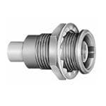
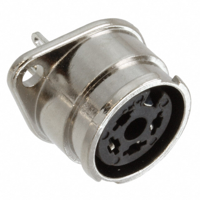
® ® ERA Fixed socket, nut fixing 15 S 9 1 Weight Part number (g) ø 10.2 M7x0.5 ø 8 ERA.00.250.NTL 2.5 P5 Panel cut-out (page 38) 5.5 maxi S 6.3 ERN Fixed socket, nut fixing, with earthing tags 15 S 9 1 Weight Part number (g) ø 10.2 M7x0.5 ø 8 ERN.00.250.NTL 2.5 P5 Panel cut-out (page 38) 5.5 maxi S 6.3 ERC Fixed socket, with thread, with slots in flange 15 5 S 9 1 0. Weight M7x 1.6 Part number (g) 2 ERC.00.250.NTL 2.6 ø 10. ø 8 P1 Panel cut-out (page 38) 5.5 maxi P3 Panel cut-out for use wihout hexagonal nut (page 38) ERE Fixed socket, nut fixing, with conical lead-in 15 S 9 1 Weight Part number (g) ø 10.2 M7x0.5 ø 8 ERE.00.250.NTL 2.8 P5 Panel cut-out (page 38) 5.5 maxi S 6.3 ERT Straight socket without thread, force or adhesive fit, with earthing tags 3 15 0 0. 1 ± 8 9 6. Weight Part number (g) 8 ø ERT.00.250.NTL 2.1 P4 Panel cut-out (page 38) www.lemo.com 13
® ® ERM Fixed socket, nut fixing, with microswitch 20 S 9 1 Weight Part number ø 10.2 M7x0.5 ø 8 ERM.00.250.NTL 3(g.0) A 5.5 maxi S 6.3 P5 Panel cut-out (page 38) B Technical characteristics on request ERX Fixed socket, with thread, with slots in flange, with earthing tags 15 1 6 1. Weight Part number (g) 8 ø ERX.00.250.NTL 2.0 P3 Panel cut-out (page 38) ECP Fixed socket with two nuts 15 2 Weight Part number (g) 5 ø 9 7x0. ø 9 ECP.00.250.NTL 3.3 M P1 Panel cut-out (page 38) 4 maxi EHP Fixed socket, nut fixing, protruding shell 15 S 9 13.5 8.5 Weight Part number (g) ø 10.2 M7x0.5 ø 6.4 ø 8 EHP.00.250.NTL 2.8 P5 Panel cut-out (page 38) 2 maxi S 6.3 ELF Fixed socket, with slotted nut, 15 long threaded shell, with earthing tags (back panel mounting) 10.5 S 7.5 2.5 Weight 5 Part number M7x0. ø 10 (g) ELF.00.250.NTL 3.1 S 6.3 1.5 mini P5 Panel cut-out (page 38) 7.0 maxi 14 www.lemo.com
® ® EPA-EPB Straight socket for printed circuit 17 7 X) L 5.08 L Weight 5 Part number 7 ( (mm) (g) ø 0. 6.8 EPA.00.250.NTN 14 3.4 ø EPB.00.250.NTN 12 3.3 P10 PCB drilling pattern (page 38) EPC Straight socket for printed circuit with clearance under the body 17 7 5x) 14 5.08 Part number Weight 7 ( (g) ø 0. 6.8 EPC.00.250.NTN 3.3 ø P10 PCB drilling pattern (page 38) EPE Fixed socket with two nuts, 17 for printed circuit 14 ø10.25x) S 9 2.5 7 Weight 0.7 ( 5 Part number (g) ø M7x0. ø 10 EPE.00.250.NTN 4.3 P1 Panel cut-out (page 38) 3.5 maxi 5.08 P12 PCB drilling pattern(page 38) EPL Elbow socket (90°) 7 for printed circuit 5.08 8 6. ø H Weight 17.5 Part number (mm) (g) EPL.00.250.NTN 10 4.3 0 7 1 P10 PCB drilling pattern (page 38) ø 0.7 (5x) EPM Elbow socket (90°) for printed circuit, 7 elevated solder tail 5.08 8 6. ø H Weight Part number (mm) (g) 17.5 EPM.00.250.NTN 13 4.6 0 7 13 1 P10 PCB drilling pattern (page 38) ø 0.7 (5x) www.lemo.com 15
® ® EPK Elbow socket (90°) for printed circuit 7 with clearance under the body 5.08 8 6. ø Weight 17.5 Part number (g) EPK.00.250.NTN 4.2 0 7 1 P10 PCB drilling pattern (page 38) ø 0.7 (5x) EPS Elbow socket (90°) with two nuts, 7 for printed circuit 5.08 2.5 M7x0.5 ø 10.2 Weight Part number (g) S 9 EPS.00.250.NTN 5.4 17.5 P1 Panel cut-out (page 38) 0 10 7 ø 1 P12 PCB drilling pattern(page 38) ø 0.7 (5x) 4 maxi EPR Elbow socket (90°) with two nuts 7 for printed circuit, with clearance 5.08 under the body (back panel mounting) M7x0.5 ø 10.2 Weight Part number S 9 2.5 (g) 17.5 EPR.00.250.NTN 5.4 10 7 ø 10 P1 Panel cut-out (page 38) P12 PCB drilling pattern(page 38) ø 0.7 (5x) 4 maxi EPY Elbow socket (90°) for printed circuit, with two vertical sockets 5.08 2.42 8 6. ø Weight Part number 21.5 (g) 8 10.5 EPY.00.250.NTN 12.8 P13 PCB drilling pattern(page 38) 7.5 7.814.3 1 9 3. ø 0.7 (6x) 16 www.lemo.com
® ® EPN Straight socket for press mounting in pair on printed circuit Weight Part number (g) EPN.00.250.NTN 3.6 0.8 5.08 P9 PCB drilling pattern(page 38) 5 1. ø 14 10.7 7 1.7 maxi 3.5 6 maximini ø 1.3 mini 8.7 8.3 ø 0.9 (2x) 2 PCA Free socket with cable collet Cable Cond. Dielectric Ø Sheath Ø Part number group Ø max maxi mini maxi PCA.00.250.NTLC15 9 0.55 1.45 1.1 1.4 PCA.00.250.NTLC22 1 0.55 1.95 1.7 2.1 ~25 PCA.00.250.NTLC27 2-3-4 0.55 1.95 2.3 2.7 PCA.00.250.NTLC31 8 0.55 1.95 2.8 3.0 5 6. ø M1 Cable assembly (page 39) S 4.5 PCS Free socket for cable crimping Dim Cable Cond. Ø Dielec. Sheath Part number L group mini maxi Ø maxi Ø maxi PCS.00.250.NTME24 30 1 0.28 0.4 0.95 2.35 PCS.00.250.NTME30 30 2 0.28 0.4 1.65 3.0 PCS.00.250.NTME31 30 3-4 0.46 0.55 1.65 3.0 L PCS.00.250.NTME44 30 5 0.28 0.4 2.65 4.35 5 PCS.00.250.NTME52 33 6 0.90 0.97 3.05 5.2 6. ø M4 Cable assembly, crimp contact (page 40) S 5.5 S 5.5 PSA Fixed socket, nut fixing, with cable collet ~25 Cable Cond. Dielectric Ø Sheath Ø Part number S 9 1 group Ø max maxi mini maxi PSA.00.250.NTLC22 1 0.55 1.95 1.7 2.1 2 PSA.00.250.NTLC27 2-3-4 0.55 1.95 2.3 2.7 ø 8 ø 10. PSA.00.250.NTLC31 8 0.55 1.95 2.8 3.0 5 S 4.5 7x0. 5.5 maxi S 6.3 M1 Cable assembly (page 39) M P5 Panel cut-out (page 38) www.lemo.com 17
® ® PSS Fixed socket, nut fixing, for cable crimping Dim Cable Cond. Ø Dielec. Sheath L Part number L group mini maxi Ø maxi Ø maxi S 9 1 PSS.00.250.NTME24 30 1 0.28 0.4 0.95 2.35 PSS.00.250.NTME30 30 2 0.28 0.4 1.65 3.0 8 0.2 PSS.00.250.NTME31 30 3-4 0.46 0.55 1.65 3.0 ø ø 1 PSS.00.250.NTME35 30 8 0.46 0.55 1.65 3.35 0.5 PSS.00.250.NTME52 33 6 0.90 0.97 3.05 5.2 S 5.5 7x 5.5 maxi S 6.3 M M4 Cable assembly, crimp contact (page 40) P5 Panel cut-out (page 38) PES Fixed socket, nut fixing, for cable crimping (back panel mounting) 30 S 6.3 2.5 Cable Cond. Ø Dielectric Ø Sheath Ø Part number group mini maxi maxi maxi 5 PES.00.250.NTME24 1 0.28 0.4 0.95 2.35 M7x0. ø 10 PES.00.250.NTME30 2 0.28 0.4 1.65 3.0 PES.00.250.NTME31 3-4 0.46 0.55 1.65 3.0 PES.00.250.NTME35 8 0.46 0.55 1.65 3.35 S 5.5 2.5 maxi M4 Cable assembly, crimp contact (page 40) P5 Panel cut-out (page 38) PFS Fixed socket, with two nuts, for cable crimping (back panel mounting) L S 9 2.5 Dim Cable Cond. Ø Dielec. Sheath Part number L group mini maxi Ø maxi Ø maxi ø 10 ø 10.2 PPFFSS..0000..225500..NNTTMMEE2341 3300 31-4 00..4268 00.5.45 10..6955 23..305 5 PFS.00.250.NTME52 33 6 0.90 0.95 3.05 5.2 0. S 5.5 7x S 6.3 M 5.5 maxi P5 Panel cut-out (page 38) Cable assembly, please contact customer services PLK Fixed elbow socket (90°), for cable crimping (back panel mounting) 18.5 S 6.3 2.5 Cable Cond. Ø Dielectric Ø Sheath Ø Part number 5 group mini maxi maxi maxi 5 M7x0. ø 10 PLK.00.250.NTLE31 3-4 0.46 0.55 1.65 3.0 5. 1 PLK.00.250.NTLE35 8 0.46 0.55 1.65 3.35 2.5 maxi S 6 P5 Panel cut-out (page 38) Cable assembly, please contact customer services 18 www.lemo.com
® ® FRT Straight plug with resistor 29 21 Weight Part number Resistor Note (g) 4 6. FRT.00.250.NTA00 shorted 4.4 ø FRT.00.250.NTA50 50 Ω0.6W 4.4 FRT.00.250.NTA100 100 Ω0.4W 4.4 S 5.5 Note: Standard, first choice alternative Non standard, on request only FLR Elbow plug (90°) with resistor 17.5 9.5 ø 9 Weight Part number Resistor 8 (g) 8. 1 FLR.00.250.NTA50 50 Ω0.6W 5.6 RAD Fixed coupler, nut fixing 22 S 9 1 Weight Part number (g) 2 ø 8 ø 10. RAD.00.250.NTM 3.8 0.5 P5 Panel cut-out (page 38) 7x 5.5 maxi S 6.3 M Note:the first contact type mentioned (page 7) is always the contact at the flange end. RMA Free coupler 22 4 Weight 6. Part number ø (g) RMA.00.250.NTM 2.7 FTR Elbow plug (90°) with socket 9 18.5 9.5 Part number Weight 5 (g) 7. 1 FTR.00.250.NTA 5.4 www.lemo.com 19
® ® FTA T-plug with two sockets in line Weight Part number (g) ø 9 30 FTA.00.250.NTF 7.8 5 9. 5 7. 1 FTL T-plug with two sockets (90°) Weight Part number (g) 28 FTL.00.250.NTF 7.1 ø 9 20 5 8. 1 FTY Straight plug with two parallel sockets Weight 29.5 Part number (g) 7 21.5 FTY.00.250.NTF 12.5 Note:Test voltage: 1.1kV (rms) / IEC 60512-2 test 4a. 6 7 ø 1 20 www.lemo.com
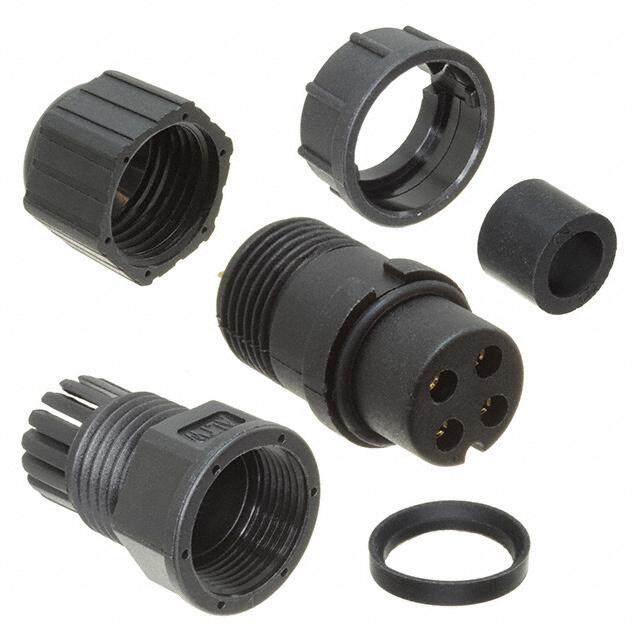
® ® Plastic housing models This plastic housing provides the ideal solution when the isolation of the connector is critical (non metallic). The FFA and ERN models in PEEK allow weight saving and can provide ease of use in applications such as medical electronic instru- mentation. Technical Characteristics Mechanical and climatical Characteristics Value Standard Test Contact retention force > 18 N IEC 60512-8 15a Cable pull off force > 100 N IEC 60512-9 17a Connector pull off force > 90 N Endurance > 5000 IEC 60512-5 9a cycles Operating temperature - 50°C + 250°C FFA Straight plug with cable collet, PEEK outer shell Cable Cond. Dielectric Ø Sheath Ø Part number group Ø max maxi mini maxi FFA.00.250.GTAC15 9 0.55 1.45 1.1 1.4 ~33.5 FFA.00.250.GTAC17 – 0.55 1.45 1.3 1.7 FFA.00.250.GTAC22 1 0.55 1.95 1.7 2.1 ~25.5 FFA.00.250.GTAC27 2-3-4 0.55 1.95 2.3 2.7 .FFA.00.250.GTAC31 8 0.55 1.95 2.8 3.0 7 ø M1 Cable assembly (page 39) S 6 ERN Fixed socket, nut fixing, with earthing tags, 15 PEEK outer shell S 9 1 Weight ø 10.2 M7x0.5 ø 9 ERN.P00a.r2t 5n0u.mGbTLer 1(g.4) 5.5 maxi S 6.3 P5 Panel cut-out (page 38) PCA Free socket with cable collet, PEEK outer shell Cable Cond. Dielectric Ø Sheath Ø Part number group Ø max maxi mini maxi PCA.00.250.GTLC15 9 0.55 1.45 1.1 1.4 ~32.5 PCA.00.250.GTLC17 – 0.55 1.45 1.3 1.7 PCA.00.250.GTLC22 1 0.55 1.95 1.7 2.1 PCA.00.250.GTLC27 2-3-4 0.55 1.95 2.3 2.7 ø7 PCA.00.250.GTLC31 8 0.55 1.95 2.8 3.0 S 6 M1 Cable assembly (page 39) www.lemo.com 21
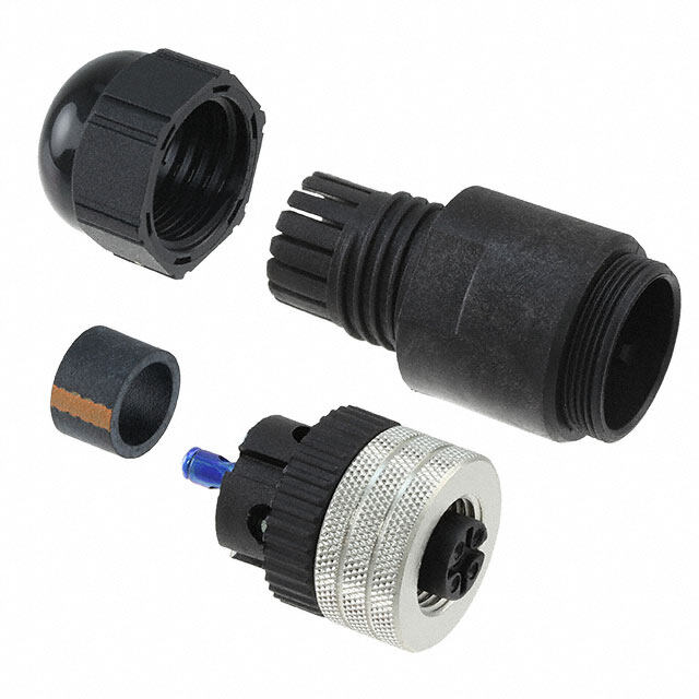
® ® Watertight or vacuumtight models A range of sealed sockets and couplers allows the device on which they are fitted to reach a protection index of IP68 as per IEC 60529 (unmated). They are fully compatible with plugs of the same series and are widely used for portable radios, military, laboratory equipment, aviation, etc. These models are identified by a letter «P» at the end of the reference for watertight model and by a «PV» for vacuum- tight models. Epoxy resin or o-rings are used to seal these models. Mechanical and climatical Characteristics Value Standard Endurance > 5000 cycles IEC 60512-5 test 9a Humidity up to 95% at 60° C Temperature range - 20° C/+100° C Salt spray corrosion test > 144h IEC 60512-6 test 11f Climatical category 20/80/21 IEC 60068-1 Leakage rate (He)1) < 10-7 mbar.l.s-1 IEC 60512-7 test 14b Maximum 60 bars IEC 60512-7 test 14d operating pressure2) Note: 1) only for vacuumtight models. Residual traces of grease used during (He) leak testing are on the o-ring. Please contact us for further details. 2) this value corresponds to the maximum allowed pressure difference for the assembled socket. HGP Fixed socket, nut fixing, watertight or vacuumtight 17 S 9 1.5 Weight Part number (g) ø 10.2 M7x0.5 ø 11 HGP.00.250.NTLP 4.2 HGP.00.250.NTLPV 4.2 8 maxi P1 Panel cut-out (page 38) HGW Fixed socket, nut fixing, watertight with rear sealing ring 15 S 9 1 Weight Part number 5 (g) ø 13 M7x0. ø 8 HGW.00.250.NTLP 4.2 3.8 mini P1 Panel cut-out (page 38) 5.8 maxi Note: Non standard, on request only HEP Fixed socket, nut fixing, watertight 18 for printed circuit (back panel mounting) 3 4.7 2.5 5.08 Weight 7 Part number 0. (g) ø11ø8.7 M7x0.5 ø HEP.00.250.NTNP 7.4 S 9 S 6.3 P5 Panel cut-out (page 38) 0.9 (4 x) 2 maxi P15 PCB drilling pattern (page 38) 22 www.lemo.com
® ® EWF Fixed socket, nut fixing, watertight or vacuumtight (back panel mounting) 17 3 S 9 Weight Part number (g) ø 11 M7x0.5 ø 10.2 EWF.00.250.NTLP 4.2 EWF.00.250.NTLPV 4.2 S 9 9.5 maxi P1 Panel cut-out (page 38) EWV Fixed socket, screw fixing, watertight or vacuumtight 17 2.6 1.5 Part number W e(gig) ht ø EWV.00.250.NTLP 3.7 5 M7x0. ø 11 7.9 EWV.00.250.NTLPV 3.7 ø P2 Panel cut-out (page 38) SWH Fixed coupler, nut fixing, vacuumtight 24.5 S 9 1.5 Weight Part number (g) ø 10.2 ø 11 SWH.00.250.NTMV 5.2 5 P1 Panel cut-out (page 38) 7x0. 5.5 maxi M Note:this model is sealed with o-rings (no epoxy). VPS Fixed socket, short shell, vacuumtight with cable crimping 24.5 (back panel mounting) 1.5max 0.5 x 7 M Cable Cond. Ø Dielectric Ø Sheath Ø ø 11 ø 7 ø 10 Part number group mini maxi maxi maxi VPS.00.250.CTLE31 3-4 0.46 0.55 1.65 3.0 S 5 P1 Panel cut-out (page 38) 16.5 Cable assembly, please contact customer service www.lemo.com 23
® ® Metal housing models with mechanical keying The straight plug and receptacle models FGG, XBG, XRG, XSG, ESG, EXG and PSG are available with a key to avoid cross mating of similar connectors. These models are not included in the NIM-CAMAC standard. The standard "G" key consists of one mechanical alignment key. Front view of the standard "G" key FGG Straight plug with key (G), with cable crimping Dim Cable Cond. Dielec. Sheath Part number L M group Ø maxi Ø maxi Ø maxi FGG.00.250.NTAE24 31 23 1 0.4 0.95 2.35 FGG.00.250.NTAE31 31 23 3-4 0.55 1.65 3.0 FGG.00.250.NTAE52 34 26 6 0.97 3.05 5.2 M5 Cable assembly, solder contact (page 41) L M Dim Cable Cond. Ø Dielec. Sheath Part number L M group mini maxi Ø maxi Ø maxi 4 ø 6. FGG.00.250.NTCE24 31 23 1 0.28 0.4 0.95 2.35 FGG.00.250.NTCE31 31 23 3-4 0.46 0.55 1.65 3.0 S 5.5 S 5.5 FGG.00.250.NTCE52 34 26 6 0.90 0.97 3.05 5.2 M4 Cable assembly, crimp contact (page 40) XBG Elbow socket (90°) with slotted nut, 7 for printed circuit with key (G) 5.08 2.5 5 0. M7x Weight Part number (g) 17.5 XBG.00.250.NTN 5.1 9 0 P1 Panel cut-out (page 38) 7 ø 1 P12 PCB drilling pattern(page 38) 3 ø 0.7 5 maxi (5 x) XRG Elbow socket (90°), with key (G), short shell 14 and slotted nut, for printed circuit, 7 screw fixing (back panel mounting) 2.5 Weight 5 Part number 7 M7x0. ø 10 XRG.00.250.NTN 3(g.8) 3 2 x M 1.4 4 maxi P1 Panel cut-out (page 38) P14 PCB drilling pattern(page 38) 24 www.lemo.com
® ® XSG Elbow socket (90°) with slotted with key (G), 7 S 9 and hex nuts for printed circuit 5.08 2.5 M7x0.5 ø10.3 Part number We(gig) ht 17.5 XSG.00.250.NTN 5.4 P1 Panel cut-out (page 38) 0 7 ø 1 P12 PCB drilling pattern(page 38) 3 ø 0.7 4 maxi (5 x) ESG Fixed socket with two round nuts, threaded shell,with key (G) (back panel mounting) 15 2 ø 9 7x0.5 ø 9 Part number We(gig) ht M ESG.00.250.NLL 3.1 4 maxi P1 Panel cut-out (page 38) EXG Elbow socket (90°) with slotted nut for printed 2.5 7 circuit,with key (G),with o-ring on flange 5.08 (back panel mounting). Special shell design. 5 ø10 M7x0. Weight 17.5 Part number (g) 0 EXG.00.250.NTNY 6.3 11 9 ø 1 P1 Panel cut-out (page 38) ø 0.7 5 maxi P15 PCB drilling pattern(page 38) ø 1.2 (4x) PSG Fixed socket, nut fixing, with key (G) with cable crimping L S 9 1 Dim Cable Cond. Ø Dielec. Sheath Part number L group mini maxi Ø maxi Ø maxi 2 PSG.00.250.NTME24 30 1 0.28 0.4 0.95 2.35 8 0. ø ø 1 PSG.00.250.NTME31 30 3-4 0.46 0.55 1.65 3.0 5 PSG.00.250.NTME52 33 6 0.90 0.97 3.05 5.2 0. S 5.5 7x 5.5 maxi S 6.3 M M4 Cable assembly, crimp contact (page 40) P5 Panel cut-out (page 38) www.lemo.com 25
® ® Threaded-coupling models The straight plug and receptacle models FVS, EPE and EPS are available with threaded coupling. On sockets, 3.2 mm minimum length of free threading must be available to ensure screw mating. These models are not included in the NIM-CAMAC standard. FVS Straight plug for cable crimping Dim Cable Cond. Dielec. Sheath Part number L M group Ø maxi Ø maxi Ø maxi FVS.00.250.NTAE24 31 23 1 0.4 0.95 2.35 FVS.00.250.NTAE31 31 23 3-4 0.55 1.65 3.0 FVS.00.250.NTAE52 34 26 6 0.97 3.05 5.2 M5 Cable assembly, solder contact (page 41) Dim Cable Cond. Ø Dielec. Sheath L Part number L M group mini maxi Ø maxi Ø maxi M FVS.00.250.NTCE24 31 23 1 0.28 0.4 0.95 2.35 FVS.00.250.NTCE25 31 23 1 0.28 0.4 1.15 2.35 ø 9 FVS.00.250.NTCE30 31 23 2 0.28 0.4 1.65 3.0 FVS.00.250.NTCE31 31 23 3-4 0.46 0.55 1.65 3.0 S5 S5 FVS.00.250.NTCE35 31 23 8 0.46 0.55 1.65 3.35 FVS.00.250.NTCE44 31 23 5 0.28 0.4 2.65 4.35 FVS.00.250.NTCE52 34 26 6 0.90 0.97 3.05 5.2 FVS.00.250.NTCE56 34 26 7 0.90 0.97 3.05 5.45 M4 Cable assembly, crimp contact (page 40) EPE Straight socket with two nuts, 17 for printed circuit 14 2.5 3.2 mini 7 Weight Part number ø10.2 M7x0.5 ø 10 EPE.00.250.NTN 4(g.3) 7 ø 0.(5x) S 9 0.7 maxi 5.08 P1 Panel cut-out (page 38) P12 PCB drilling pattern(page 38) EPS Elbow socket (90°) with two nuts, 7 for printed circuit 5.08 2.5 3.2 mini M7x0.5 ø 10.2 Part number Weight (g) S 9 EPS.00.250.NTN 5.4 17.5 P1 Panel cut-out (page 38) 0 10 7 ø 1 P12 PCB drilling pattern(page 38) ø 0.7 0.7 maxi (5 x) 26 www.lemo.com
® ® Adaptors ABF Adaptor from LEMO plug to BNC socket 36 Weight Part number (g) 28 ABF.00.250.NTA 8.3 5 11. ø APF Adaptor from LEMO plug to CINCH socket Colour Weight 4.6 35.5 Part number of the ring (g) ø APF.00.250.DTAB white 7 ø 8.3 ø 6.4 APF.00.250.DTAR red 7 43.5 ABA Adaptor from LEMO socket to BNC plug 28.5 Weight 4.5 Part number (g) 1 ø ABA.00.250.NTL 18.7 ABC Adaptor from LEMO socket to BNC socket 29.5 Weight 5 Part number 4. (g) 1 ø ABC.00.250.NTM 17 ABD Adaptor from LEMO socket 2A to BNC fixed socket F - 29.5 E N U S 16 S 17 8 2-2 Part number Weight 1/ (g) 9.5 ABD.00.250.NTM 21.4 1 ø P7 Panel cut-out (page 38) S 11.7 5 maxi www.lemo.com 27
® ® ABB Adaptor from LEMO fixed socket to BNC socket A 2 F - 25 NE U S 11 3/8-32 Part number We(gig) ht ABB.00.250.NTM 9.4 P6 Panel cut-out (page 38) S 8.7 9.5 maxi ACA Adaptor from LEMO socket to C plug 31 Weight Part number (g) 5 9. ø 1 ACA.00.250.NTL 32 Note: Non standard, on request only AGH Adaptor from LEMO socket to UHF plug 26 Weight 8.5 Part number (g) 1 ø AGH.00.250.NTL 13.8 ANA Adaptor from LEMO socket to N plug 33.5 Weight Part number (g) 5 0. ANA.00.250.NTL 38 2 ø ANB Adaptor from LEMO socket to N socket 45.5 Weight 5 Part number 7. (g) 1 ø ANB.00.250.NTM 61.7 5/8 - 24 UNEF - 2A Note: Non standard, on request only 28 www.lemo.com
® ® ANC Adaptor from LEMO socket A to N fixed socket 2 F - NE 46 U 4 S 19 2 8 - Part number Weight 5/ (g) 8 ANC.00.250.NTM 63.5 1. 2 ø P8 Panel cut-out (page 38) S 13.5 17 maxi Note: Non standard, on request only ASA Adaptor from LEMO socket to SMA plug 30 Weight ø 9 Part number (g) ASA.00.250.NTL 4.9 S 8 ASB Adaptor from LEMO socket to SMA socket A 2 S - N U 6 3 4 - 30.8 1 / Part number Weight (g) 9 ø ASB.00.250.NTM 4.6 S 8 ASF Adaptor from LEMO plug to SMA socket A 2 S - N 6 U 31.8 3 4 - 23.8 Part number Weight 1 / (g) ASF.00.250.NTA 4.6 9 ø S 8 ASG Adaptor from LEMO plug to SMA plug 31 23 Weight Part number 9 (g) ø ASG.00.250.NTC 4.9 S 8 www.lemo.com 29
® ® Variant Bend relief for models with collet (letter Z in the variant position) Need to be ordered Need to be Reference ordered separately (see page 33) C15Z GMA.00.0ll.Dl C17Z GMA.00.0ll.Dl C22Z – C27Z GMD or GMB.00.0ll.Dl C31Z GMD or GMB.00.0ll.Dl C52Z GMA.0B.0ll.Dl K37Z GMA.0B.0ll.Dl K42Z GMA.0B.0ll.Dl D42Z GMA.0B.0ll.Dl D52Z GMA.0B.0ll.Dl Note: The “GMD” are thin bend reliefs (for very flexible cables) Bend relief for models for cable crimping (no letter in the variant position) The bend relief can be fitted directly over the crimp ferrule Need to be ordered Need to be Reference ordered separately (see page 33) E24 GMD or GMB.00.0ll.Dl E25 GMD or GMB.00.0ll.Dl E30 GMD or GMB.00.0ll.Dl E31 GND.00.028.Dl E32 GMD or GMB.00.0ll.Dl E35 – E44 – E52 – E56 – Note: The “GMD” are thin bend reliefs (for very flexible cables) 30 www.lemo.com
® ® Assembled cables MFB models MSB models Delay lines Assembled Cables Delay Length Part number (ns) Part number Part number (cm) Part number MFB.00.250.RTE005 0.5 MSB.00.250.RTE005 MFB.00.250.LTE010 10 MSB.00.250.LTE010 MFB.00.250.RTE010 1.0 MSB.00.250.RTE010 MFB.00.250.LTE020 20 MSB.00.250.LTE020 MFB.00.250.RTE020 2.0 MSB.00.250.RTE020 MFB.00.250.LTE030 30 MSB.00.250.LTE030 MFB.00.250.RTE030 3.0 MSB.00.250.RTE030 MFB.00.250.LTE040 40 MSB.00.250.LTE040 MFB.00.250.RTE040 4.0 MSB.00.250.RTE040 MFB.00.250.LTE050 50 MSB.00.250.LTE050 MFB.00.250.RTE050 5.0 MSB.00.250.RTE050 MFB.00.250.LTE060 60 MSB.00.250.LTE060 MFB.00.250.RTE060 6.0 MSB.00.250.RTE060 MFB.0F0.R25T0.LTE080 80 MSB.00.250.LTE080 MFB.00.250.RTE080 8.0 MSB.00.250.RTE080 MFB.00.250.LTE100 100 MSB.00.250.LTE100 MFB.00.250.RTE100 10.0 MSB.00.250.RTE100 MFB.00.250.LTE150 150 MSB.00.250.LTE150 MFB.00.250.RTE160 16.0 MSB.00.250.RTE160 MFB.00.250.LTE200 200 MSB.00.250.LTE200 MFB.00.250.RTE200 20.0 MSB.00.250.RTE200 MFB.00.250.LTE300 300 MSB.00.250.LTE300 MFB.00.250.RTE320 32.0 MSB.00.250.RTE320 MFB.00.250.LTE400 400 MSB.00.250.LTE400 MFB.00.250.RTE640 64.0 MSB.00.250.RTE640 MFB.00.250.LTE500 500 MSB.00.250.LTE500 Note: the standard cable used to manufacture these cable assemblies is according to IEC.50.2.1 standard. On request this type of cable can be replaced by other coaxial cables. Other cable lengths are available on request. Accessories Fitting of the cord Slide the plug into the loop of the cord. Place the loop into the groove in front of the collet nut and tighten the loop. BFG Caps for plug with or without keying Weight N1) Part number (g) (mm) BFG.00.100.PCSG 0.7 60 10 Note: 1) the tolerance on this dimension is ± 5 mm. Upon request this cap can be supplied in black and the last letter “G” 5 of the part number should be replaced with “N”. 9.8 ø 7. l Body material: Polyoxymethylen (POM) grey l Cord material: Polyamid 6, grey N l O-ring material: Silicone rubber l Maximum operating temperature: 100°C l Watertightness: IP61 according to IEC 60529 www.lemo.com 31
® ® BRA Blanking cap for fixed socket and free straight socket 9 3.5 Weight N1) Part number 5 (g) (mm) ø 7. 9.8 BRA.00.200.PCSG 0.6 60 ø 3.5 N NUopoten: r1e) qthuee stot lethriasn ccaep o nc athni sb ed imsuepnpsliioend iisn ±b 5la mckm a.n d the last letter “G” of the part number should be replaced with “N”. l O-ring material: Silicone rubber l Body material: Polyoxymethylen (POM) grey l Maximum operating temperature: 100°C l Cord material: Polyamid 6, grey l Watertightness: IP61 according to IEC 60529 Fitting of the cord Slide the socket into the loop of the cord. Place the loop into the groove in front of the collet nut and tighten the loop. BRD Blanking cap for free socket Weight N1) Part number (g) (mm) BRD.00.200.PCSG 0.5 60 9 3.5 Note: 1) the tolerance on this dimension is ± 5 mm. 5 Upon request this cap can be supplied in black and the last letter “G” ø 7. 9.8 of the part number should be replaced with “N”. l Body material: Polyoxymethylen (POM) grey N l Cord material: Polyamid 6, grey l O-ring material: Silicone rubber l Maximum operating temperature: 100°C l Watertightness: IP61 according to IEC 60529 BRE Blanking cap for fixed socket, 8.8 free socket and coupler 7.5 3.5 Part number Weight N1) (g) (mm) BRE.00.200.NAS 6.5 60 8 ø Note: 1) the tolerance on this dimension is ± 5 mm. N l Body material: Brass (UNS C 38500), nickel-plated (3 µm) 5 l Cable material: Stainless steel ø 3. l O-ring material: Silicone rubber or FPM l Maximum operating temperature: 250°C l Watertightness: IP61 according to IEC 60529 GCD Earthing cap L C ø ø 8 Part number Cable Dim. group L C S 7 GCD.00.020.LA 1 12 2.0 GCD.00.032.LA 2-3-4 16 3.2 GCD.00.050.LA 6 19 5.0 Note: the shield braid of the cable should be soldered onto the back of the cap screwed on the socket outer shell. l Material: Brass (UNS C 38500) gold-plated (0.5 µm) 32 www.lemo.com
® ® GM(cid:129) Bend relief Dim. ø Cable Nut for fitting the Part number A L max min bend relief part nb A ø GMA.00.012.D(cid:129) 1.2 22 1.4 1.1 FFM.00.130.LN GMA.00.018.D(cid:129) 1.8 22 2.1 1.8 FFM.00.130.LN GMB.00.025.D(cid:129) 2.5 22 2.8 2.5 FFM.00.130.LN L GMB.00.028.D(cid:129) 2.8 22 3.1 2.8 FFM.00.130.LN GMB.00.032.D(cid:129) 3.2 22 3.5 3.2 FFM.00.130.LN GMD.00.025.D(cid:129) 2.5 22 2.8 2.5 FFM.00.130.LN GMD.00.028.D(cid:129) 2.8 22 3.1 2.8 FFM.00.130.LN GMD.00.032.D(cid:129) 3.2 22 3.5 3.2 FFM.00.130.LN Note: a) for use with crimp models and nut for fitting a bend relief. GMA.0B.025.D(cid:129) 2.5 24 2.9 2.5 FFM.0B.130.LC b) the last letter of the part number “(cid:129)” specifies the colour. GMA.0B.030.D(cid:129) 3.0 24 3.4 3.0 FFM.0B.130.LC Refer to the table below, for GRA washers, to define another colour and replace the letter “(cid:129)” by the one corresponding GMA.0B.035.D(cid:129) 3.5 24 3.9 3.5 FFM.0B.130.LC to the colour required. GMA.0B.040.D(cid:129) 4.0 24 4.4 4.0 FFM.0B.130.LC c) material: TPU (Thermoplastic Polyurethane) d) operating temperature: -40°C + 80°C GMA.0B.045.D(cid:129) 4.5 24 5.2 4.5 FFM.0B.130.LC GRA Insulating washers Weight Part number (g) GRA.00.269.G(cid:129) 0.1 Note: a) sockets and plugs mounted on panels can be fitted with insulating washers. The nine colours available combined with those for the bend reliefs makes colour coding possible. 1.8 b)the last letter of the part number “(cid:129)” specifies the colour. ø10 Refer to the table below to define another colour and replace 1 the letter “(cid:129)” by the one corresponding to the colour required. 6.4 c) material: Polyamid d)operating temperature: -40°C + 80°C 8 8. ø Ref. Colour Ref. Colour Ref. Colour 3.5 maxi 8 A blue J yellow R red B white M brown S orange G grey N black V green Spare Parts FFS Crimp ferrule Cable Dim. Part number group øA øB L FFS.00.160.DN 1 3.1 2.4 8 FFS.00.161.MN 2-3-4 3.8 3.05 8 A L B ø ø FFS.00.162.DN 8 4.4 3.4 8 FFS.00.163.DN 5 5.3 4.4 8 FFS.00.164.DN 6 6.2 5.25 11 CRK.0A.160.DN 7 6.2 5.5 11 Note: sockets and plugs to be crimped are always supplied with a crimp ferrule. To order this accessory separately, use the above part numbers. ● Material: Copper (UNS C 18700) nickel-plated (3µm) www.lemo.com 33
® ® GBB Tapered washer ø 9 2 ø 7.1 Weight Part number (g) GBB.00.250.LN 0.2 Note:to order this accessory separately, use the above part number. ● Material: Brass (UNS C 38500) nickel-plated (3 µm) GBA Locking washer ø9.5 1 ø7.1 Weight Part number (g) GBA.00.250.FN 0.2 Note:sockets and plugs are always supplied with a locking washer. To order this accessory separately, use the above part number. GEA Hexagonal nut 9 Weight Part number M7 x 0.5 2 (g) GEA.00.240.LN 0.6 2 ø 10. Ndaortde.: Tsoo cokredtesr athnids apclucgess saorrey ssuepppalriaetde lwy,i tuhs ea thheex aagboonvael pnaurtt ansu mstbaenr-. The last letters “LN” of the part number refer to the nut material and treatment. If a nut in aluminium alloy is desired, replace the last letters of the part number by “PT”. ● Material: - Brass (UNS C 38500) nickel-plated (3 µm) - Aluminium alloy natural anodized GEB Round nut ø 9 M7 x 0.5 4 Weight Standard Part number (g) for models GEB.00.240.LN 0.8 ECP, ESG Note:to order this accessory separately, use the above part number. ● Material: Brass (UNS C 38500) nickel-plated (3 µm) GEC Conical nut 8 M7 x 0.5 2.5 Weight Part number (g) 10 GEC.00.240.LN 0.6 ø Note:to order this accessory separately, use the above part number. ● Material: Brass (UNS C 38500) nickel-plated (3 µm) GEG Notched nut ø A e L Part number Dimensions (mm) Standard A B e L for models EPE, EPS, EPR B ø GEG.00.240.LN 8.7 10 M7 x 0.5 2.5 PES, PFS, PLK, VPS, HEP Note: to order this accessory separately, use the above part numbers. ● Material: Brass (UNS C 38500) nicked-plated (3 µm) 34 www.lemo.com
® ® GEB Slotted nut ø A L e Dimensions (mm) Standard Part number A B e L for models B ELF, XBG, ø GEB.00.242.LN 8.5 10 M7 x 0.5 2.5 XRG, XSG, EXG Note: to order this accessory separately, use the above part numbers. ● Material: Brass (UNS C 38500) nicked-plated (3 µm) GCA Earthing Washer ø 9.5 0.4 ø 7.1 Weight Part number (g) 2 8. GCA.00.255.LT 0.2 1 ● Material: Brass (UNS C 27400) treated CuSnZn (2 µm) Tooling DCG Spanner for hexagonal nut 50 Part number 40 Part number of the nut DCG.91.149.0TN GEA.00.240.LN ● Material: Blackened steel ø 14 DCA Spanner for hexagonal nut with locator 50 for flats on socket thread axi Part number m Part number 5 of the nut 6 DCA.91.149.0TN GEA.00.240.LN ø 14 ● Material: Blackened steel DCH Spanner for notched nut ø 10.1 ø 12.8 Part number Part number of the nut 4 12 DCH.91.101.PA GEG.00.240.LN 48.3 ● Material: blue polyurethane www.lemo.com 35
® ® DCB Spanner for slotted nut 60 Part number Part number of the nut 9 1 DCB.91.455.0LN GEB.00.242.LN ø 11 ● Material: Steel, nicked plated DCB Spanner for round nut 50 Part number Part number of the nut 0 4 DCB.91.119.0TN GEB.00.240.LN ø 11 ● Material: Blackened steel DCN Spanner for assembling plug with 3 latches ø 9 12 Part number 2 4 DCN.91.905.0TK ● Material: Blackened steel DCP Flat spanner for collet nut Dimensions Part number L M N S1 M DCP.99.045.TC 70 2 10.5 4.5 DCP.99.050.TC 78 2 12.6 5.0 S1 DCP.99.055.TC 78 2 12.6 5.5 S1 DCP.99.060.TC 78 2 12.6 6.0 N L ● Material: Chrome-plated steel DCR Extraction tool for plugs Part number 120 DCR.91.106.0PN 3 ø 10. ø 12 ● Material: Black Polypropylene 9 Note: this type of tool has been produced in order to facilitate the mating and unmating of plugs and is particularly useful in high density applications. 36 www.lemo.com
® ® DPE Crimping tool with die Cable Crimp collet Part number group ref. DPE.99.000.00 Crimping tool with no die DPE.99.123.1K 1 E24 DPE.99.123.8K 2-3-4 E30, E31 DPE.99.124.3K 8 E35 DPE.99.125.2K 5 E44 DPE.99.176.2K 6-7 E52, E56 DPN Dies D ie d i m ension Cable Part number For contacts For shield group A B L A B DPN.99.123.1K 1 1.29 0.91 2.0 3.10 2.70 L A DPN.99.123.8K 2-3-4 1.29 0.91 2.0 3.80 3.30 A DPN.99.124.3K 8 1.29 0.91 2.0 4.36 3.78 DPN.99.125.2K 5 1.29 0.91 2.0 5.20 4.50 B DPN.99.176.2K 6-7 1.71 1.21 2.5 6.20 5.37 B for contacts for shield ● Dies material: Blackened steel www.lemo.com 37
® ® Panel cut-outs Panel cut-out Dimensions P1 P2 P3 P4 P5 Cut-out Model A B L e Lmini ECP-EPE-EPR-EPS-ERC EWF-EXG-FAB-HGP P1 7.1 – 14.5 – + 0.1B 0 HXSGGW-X-SRWGH-VPS-XBG P2 EWV – – 12.0 M7x0.5 e ø A + 0.1 0 P3 ERC-ERX – – 9.0 M7x0.5 P4 ERT 6.92+00.02 – – – EHP-ELF-ERA-ERE-ERM P6 P7 P8 P5 ERN-FAA-FAN-PES-PFS 7.1 6.4 14.5 – PLK-PSA-PSG-PSS1) Lmini P6 ABB 9.7 9.0 15.0 – + 0.1B 0 PP78 AABNDC 1126..91 1113..77 2204..50 –– ø A + 0.1 Note:1) If these models are used with a tapered washer GBB, 0 the panel cut-out must be according P1. Recommended mounting nut torque: 1 Nm. PCB drilling pattern Dimensions P9 P10 P11 P12 P15 Drill Model A B C B ø A+ 00.1 P9 EPN 1.0 5.08 – EPA-EPB-EPC-EPL-EPK P10 0.8 5.08 0.8 EPM-FPL = B P11 FPA 0.8 5.08 1.1 = P12 EPE-EPS-EPR-XSG 0.8 5.08 0.8 ø C+ 0.1 0 P15 HEP, EXG 1.3 5.08 0.8 P13 EPY 0.8 5.08 0.8 P14 XRG 1.8 5.5 0.8 P13 B ø A+ 0.1 = = 0 B ø C+ 0.1 0 P14 ø A+ 0.1 B 0 2.05 ø C+ 0.1 0 38 www.lemo.com
® ® Cable assembly Terminating of plugs and straight sockets with cable collet M1 M2 M3 5 4 3 1 Straight plug 2 5 Free socket 4 3 5 1 Fixed socket nut fixing 1. Cable preparation First place the bend relief (if to be used) on the cable. L ± 0.2 Strip the cable according to dimensions below. S ± 0.2 Cable M1 M2 M3 T ± 0.2 group T S L T S L T S L 1-2-3-4-8 4 4.5 9 – – – 5 5.5 10 6-7 – – – 7.5 8.5 13 – – – 2. Cable termination 2.1 Place the collet nut j and the collet k on the cable. Fold back the shield braid onto the conical part of the collet, and trim to the outer edge of the collet 2.2 Slide the subassembly l to trap the shield braiding and solder the Crimp central conductor into the contact. Crimp 2.3 Slide the insulator m onto the subassembly l until it rests against the earthing sleeve of the subassembly l. 2.4 Slide the assembly into the connector outer shell n. Screw the collet nut j into the connector outer shell n using the appropriate tool and tighten to a torque of 0.25 Nm (see “Tooling” on page 35, 36 and 37). Push the bend relief (if used) onto the collet nut. Note: these terminating instructions apply to the following models: M1 = FFA, FFE, FFF, PCA, PSA M2 = FFY M3 = FFC www.lemo.com 39
® ® Terminating of plugs and straight sockets with cable crimping (crimp contact) M4 4 3 2 Straight plug 1 4 Free socket 3 2 4 Fixed socket nut fixing 1. Cable preparation L ± 0.2 First place the bend relief (if to be used) on the cable. Strip the cable according to dimensions below. S ± 0.2 T ± 0.2 Cable M4 group T S L 1-2-3-4-8 7 15 19.5 6-7 7 15 21.5 2. Cable termination 2.1 Place crimp ferrule ➀on the cable. Widen the shield braid. Slide the subassembly ➁ into the cable until the insulator rests against the dielectric and the cable conductor is visible through the contact inspection hole. 2.2 Crimp the contact with the LEMO crimping tool using the square hole (see “Tooling” on page 37). Crimp Gently pull the cable in order to check the crimping. Crimp 2.3 Slide the crimp ferrule ➀ onto the shield until it rests against the crimp backnut of the subassembly ➁. Crimp with the same LEMO crimping tool using the hexagonal opening. Slide the insulator ➂ onto the subassembly ➁. 2.4 Slide the assembly into the connector shell ➃and screw it onto the subassembly ➁. Tighten using the appropriate tool to a torque of 0.25 Nm (see “Tooling” on page 35, 36 and 37). Push the bend relief (if used) onto the crimp ferrule ➀. Note:these terminating instructions apply to the following models: M4 = FFS, FFV, PCS, PSS, PES 40 www.lemo.com
® ® Terminating of plugs and straight sockets with cable crimping (solder contact) M5 4 3 2 Straight plug 1 4 Free socket 3 2 4 Fixed socket nut fixing 1. Cable preparation L ± 0.2 First place the bend relief (if to be used) on the cable. Strip the cable according to dimensions below. S ± 0.2 T ± 0.2 Cable M5 group T S L 1-2-3-4-8 5 12 17 6-7 5 12 19 2. Cable terminating 2.1 Place the crimp ferrule ➀on the cable. Widen the shield braid. Slide the subassembly ➁ over the cable until the insulator rests against the dielectric and the cable conductor is visible through the contact solder hole. 2.2 Solder the conductor through the hole. Solder Solder 2.3 Slide the crimp ferrule ➀ onto the shield until it rests against the crimp backnut of the subassembly ➁. Crimp with the LEMO crimping tool using the hexagonal opening (see “Tooling” on page 37). Slide the insulator ➂ onto the subassembly ➁. 2.4 Slide the assembly into the connector shell ➃and screw it onto the subassembly ➁. Tighten using the appropriate tool to a torque of 0.25 Nm (see tooling on pages 35, 36 and 37). Push the bend relief (if used) onto the crimp ferrule. Note:these terminating instructions apply to the following models: M5 = FFS, FFV www.lemo.com 41
® ® Terminating of elbow plugs (90°) with cable collet (solder contact) M6 and cable crimp (solder contact) M7 3 4 5 2 3 4 2 1 1 1. Cable preparation 1. Cable preparation First place the bend relief First place the bend relief L ± 0.2 (if to be used) on the cable. L ± 0.2 (if to be used) on the cable. S ± 0.2 Sditmripe nthseio ncas bblee loacwc.ording to S ± 0.2 Sditmripe nthseio ncas bblee loacwc.ording to T ± 0.2 T ± 0.2 Cable M6 Cable M7 group T S L group T S L 1-2-3-4-8 1 3.5 6.5 1-2-3-4-8 1 4.5 9 6-7 3 4.5 11 2. Cable terminating 2. Cable terminating 2.1 Place the collet nut ➀ and 2.1 Place the cable crimp ferrule collet ➁on the cable. Fold ➀on the cable and widen back the shield braid onto the braiding. the conical part of the collet, and trim to outer edge of the collet. 2.2 Slide the assembly into 2.2 Slide the cable into the con- the connector shell ➂ nector shell ➁. Check that and tighten the collet nut ➀ cable conductor rests in the Solder using the appropriate tool Solder contact slot, tin solder the to a torque of 0.25 Nm conductor through the hole. (see “Tooling” on page 35, Slide the crimp ferrule ➀over 36 and 37). Check that the braiding until it reaches the cable conductor rests the connector shell ➁. Crimp in the contact slot, solder with the LEMO crimp tool the conductor through using the hexagonal opening the hole. (see “Tooling” on page 37). 2.3 Place the insulating sleeve ➃ 2.3 Place the insulating sleeve ➂ over the soldered contact. over the soldered contact. 2.4 Close the access hole with 2.4 Close the connector hole the flat screw ➄. with the flat screw ➃. Push the bend relief (if used) Push the bend relief (if used) onto the collet nut ➀. onto the crimping tube ➀. Note:these terminating instruc- Note:these terminating instruc- tions apply to the following tions apply to the following models: models: M6 = FLA M7 = FLS, FLV 42 www.lemo.com
S E I R E S 1 0 www.lemo.com
® ® 01 Series The plugs and sockets of the 01 series are amongst the smallest available 50 coax connectors with a self-latching Ω intermating capability. In spite of their small size and light weight, their technical characteristics remain excellent. Available in a wide range of housing configurations, they are especially useful when connecting onto printed circuit boards. Metal housing models (page 46) Fixed plug Straight plugs Fixed sockets Elbow socket Fixed socket Fixed coupler FPA FFS ERA EPL PSS RAD Elbow plugs Free socket Free coupler FFH Plug with ECP resistor FLS PCS RMA EPA FRT T-plug with two sockets FLH FTA Adaptors (See page 50) T-coupler RTA ABA Threated-latching models (See page 50) FVS EVP HEV 44 www.lemo.com
® ® Part Numbering System Plug FFS . 01 . 250 . D L A E 31 Free socket PCS . 01 . 250 . D L L E 31 Cable ø Collet type: E = with cable crimping Contact type: A = male solder L = female solder Fixed plug FPA . 01 . 250 . D L D Fixed socket ERA . 01 . 250 . D L L Contact type: L = female solder N = female print D = male print Fixed coupler RAD . 01 250 . D L M Contact type: Model: (page 44) M = female-female F = female-female-male X = female-female-female Series: 01 Insulator: Insert configuration: L = PCTFE 250 = coaxial (50 ) Ω Housing : N = brass nickel-plated 1) D = brass gold-plated Note: 1) treatment not available for the printed circuit models Part Number Example FFS.01.250.DLAE31 = straight plug for cable crimping, 01 series, coaxial type 50 Ω, outer shell is gold-plated brass, PEEK insulator, male solder contact, type E crimp ferrule for cable group 2, 3 or 4. Part Section Showing Internal Components Fixed socket Straight plug 4 2 3 1 1 5 6 2 4 3 1 outer shell 1 outer shell 2 female contact 2 latch sleeve 3 hexagonal nut 3 crimp ferrule 4 insulator 4 crimp backnut 5 male contact 6 insulator www.lemo.com 45
® ® Metal housing models Technical Characteristics Mechanical and climatical Voltage Standing Wave Ratio Characteristics Value Standard Test The VSWR (Voltage Standing Wave Ratio) is the value representing the power reflected in a connection. In Contact retention force > 60 N IEC 69512-8 15a most cases, the working frequency range is where Cable pull off force1) > 100 N IEC 69512-9 17c VSWR is ≤ 1.25. Connector pull off force > 110 N IEC 69512-8 15f Endurance > c1y0c0l0es IEC 69512-5 9a 1 Operating temperature - 55°C + 230°C VSWR Note: 1)Depending on cable design 1.3 1N = 0.102 kg 50Ω Electrical 1.2 Characteristics Value Standard Method Impedance 50 Ω – Operating voltage (50 Hz) 0.3 kV rms – 1.1 Test voltage (50 Hz) 1.0 kV rms IEC 60512-2 4a Rated current 4 A IEC 60512-3 5a Contact resistance < 6 m Ω IEC 60512-2 2a Screen resistance < 3.5 m Ω 1.0 1000 2000 3000 4000 5000 f Insulating resistance > 1012Ω IEC 60512-2 3a (MHz) FFS + PCS VSWR see chart N°1 beside Note: VSWR measured with a RG-174 A/U cable. According to IEC 60169-1-1 standard FFS Straight plug for cable crimping 20 Cable Cond. Dielectric Ø Sheath Ø 14.5 Part number group Ø max max max 5 FFS.01.250.DLAE24 1 0.55 0.95 2.35 ø FFS.01.250.DLAE31 2-3-4 0.55 1.65 3.0 S 4 S 4 M1 Cable assembly (page 53) FFH Straight plug, non-latching for cable crimping 18 13 Cable Cond. Dielectric Ø Sheath Ø Part number group Ø max max max 5 ø FFH.01.250.DLAE31 2-3-4 0.55 1.65 3.0 S 4 M1 Cable assembly (page 53) 46 www.lemo.com
® ® FLS Elbow plug (90°) for cable crimping 12.1 6.6 ø 7.5 Cable Cond. Dielectric Ø Sheath Ø Part number group Ø max max max FLS.01.250.(cid:129)LAE24 1 0.5 0.95 2.35 2 1 FLS.01.250.(cid:129)LAE31 2-3-4 0.5 1.65 3.0 M2 Cable assembly (page 53) (cid:129) = material of shell D or N FLH Elbow plug (90°) non-latching, for cable crimping 11 6 Part number Cable Cond. Ø Dielectric Ø Sheath Ø group maxi maxi maxi 4.5 FLH.01.250.(cid:129)LAE31 2-3-4 0.4 1.65 3.0 1 M3 Cable assembly, crimp contact (page 53) (cid:129) = material of shell D or N FPA Straight plug, non-latching, for printed circuit 13 3 5 1 6 Part number Weight (g) FPA.01.250.DLD 1.5 ø 0.9 P4 PCB drilling pattern (page 53) ERA Fixed socket, nut fixing 10.5 5 0. 4 M5x ø 6 Part number We(gig) ht 8 ø ERA.01.250.(cid:129)LL 1.3 S 7 S 5 P1 Panel cut-out (page 53) 2 max (cid:129) = material of shell D or N ECP Fixed socket, nut fixing (back panel mounting) 10.5 5 5.7 M5x0. Part number Weight (g) 7 ø ECP.01.250.(cid:129)LL 1.1 3.5 max P1 Panel cut-out (page 53) (cid:129) = material of shell D or N www.lemo.com 47
® ® EPA Straight socket for printed circuit 12 3 1 6 Part number Weight (g) 8 5. EPA.01.250.DLN 1.6 ø ø 0.9 P4 PCB drilling pattern (page 53) EPL Elbow socket (90°) for printed circuit 12.5 6 8.5 Part number Weight 6 (g) 0 ø 1 EPL.01.250.DLN 3.2 3 1 ø 0.9 P4 PCB drilling pattern (page 53) 6 PCS Free socket for cable crimping 18 Cable Cond. Dielectric Ø Sheath Ø Part number group Ø max max max ø 5 PCS.01.250.DLLE24 1 0.55 0.95 2.35 PCS.01.250.DLLE31 2-3-4 0.55 1.65 3.0 S 4 S 4 M1 Cable assembly (page 53) PSS Fixed socket, nut fixing, for cable crimping 18 0.5 S 7 4 Part number Cable Cond. Dielectric Ø Sheath Ø 5x group Ø max max max M PSS.01.250.DLLE24 1 0.55 0.95 2.35 ø 8 ø 6 PSS.01.250.DLLE31 2-3-4 0.55 1.65 3.0 S 4 3 maxi S 5 M1 Cable assembly (page 53) P1 Panel cut-out (page 53) FRT Straight plug with resistor 17 11.5 Part number Resistor Weight ø 5 (g) FRT.01.250.DLA50 50 Ω 0.6W 1.0 Note: Non standard, on request only 48 www.lemo.com
® ® RAD Fixed coupler, nut fixing 14 5 0. 4 5x 5. M Part number Weight ø 6.5 ø 8 RAD.01.250.DLM 1(g.8) S 5 S 7 P2 Panel cut-out (page 53) 2 maxi Note: Non standard, on request only RMA Free coupler 14 Part number Weight 5 (g) ø RMA.01.250.DLM 1.1 FTA T-plug with two sockets in line ø 7.5 19 6.8 3 Part number We(gig) ht 2. 1 FTA.01.250.DLF 2.6 Note: Non standard, on request only RTA T-coupler with three sockets 19 6 Part number Weight (g) 8 1. RTA.01.250.DLX 2.5 1 www.lemo.com 49
® ® Threaded-latching models FVS Straight plug, threaded latching for cable crimping 20 18 Cable Cond. Dielectric Ø Sheath Ø Part number 6.3 group Ø max max max ø FVS.01.250.NKAE31 2-3-4 0.55 1.65 3.0 6.5 S 4 S 4 M1 Cable assembly (page 53) EVP Fixed socket, nut fixing for threaded latching plug 5 10.5 x0. 4 5 M 6 ø ø 8 Part number We(gig) ht S 7 M5x0.5 EVP.01.250.NKL 1.2 2 max P1 Panel cut-out (page 53) HEV Fixed socket, round nut fixing for threaded latching plug, watertight 12.5 (back panel mounting) 5.5 maxi 5.0 mini 2 2 0.5 x 5 M ø8 ø6 Part number We(gig) ht 3 min HEV.01.250.NKL 2.3 ~ 78mm S 6 AWG 28 P3 Panel cut-out (page 53) ~ 88mm Note:this model is fitted with 2 wires AWG28 soldered before potting Adaptors ABA Adaptor from LEMO socket to BNC plug Part number Weight (g) 27 ABA.01.250.NLL 17.5 5 4. 1 ø 50 www.lemo.com
® ® Spare parts FFS Crimp ferrule A L B Part number Cable Dim. ø ø group ØA ØB L FFS.01.160.DA 1 3.1 2.4 6 FFS.01.161.DA 2-3-4 3.8 3.05 6 FFH.01.161.D(cid:129) 1) 2-3-4 3.8 3.1 7 Note:1) for models FFH and FLH Sockets and plugs to be crimped are always supplied with a crimp ferrule. To order this accessory separately, use the ● Material: Copper (UNS C 18700) nickel (3µm) + gold plated (0.5µm) above part numbers. GEA Hexagonal nut 7 e 2 e Models Weight Part number (mm) (g) 8 ø GEA.01.240.LN M5x0.5 ERA, EVP, PSS 0.39 GEA.01.241.LN M5.5x0.5 RAD 0.31 ● Material: Brass (UNS C 38500) nickel-plated (3 µm) Note:to order this accessory separately, use the above part number. GEB Round nut A M5 x 0.5 2 A Slot Weight Part number Models (mm) nb. (g) GEB.01.240.LN Ø 7 ECP 2 0.30 1 GEB.01.244.LN Ø 8 HEV 4 0.50 Note:to order this accessory separately, use the above part number. ● Material: Brass (UNS C 38500) nickel-plated (3 µm) www.lemo.com 51
® ® Tooling DCB Spanner for round nut 40 (for ECP and HEV model) Part number Part number 39 of the nut 4.8 DCB.91.097.0TN GEB.01.240.LN / GEB.01.244.LN 1 ø 7.1 ● Material: Blackened steel DPE Crimping tool with die Cable Crimp collet Part number group ref. DPE.99.000.00 Crimping tool with no die DPE.99.003.1K 1) 1 E24 DPE.99.003.8K 2) 2-3-4 E31 Note:1) Hex cavity of DPE.99.123.1K can also be used 2) Hex cavity of DPE.99.123.8K can also be used DPN Dies A Die dimension Cable Part number For shield group B A B DPN.91.003.1K 1 3.10 2.70 DPN.91.003.8K 2-3-4 3.80 3.30 for shield ● Dies material: Blackened steel DCP Flat spanner Dimensions (mm) Part number L M N S1 M DCP.99.040.TC 70 0.95 10.5 4.0 DCP.99.045.TC 70 2.00 10.5 4.5 S1 DCP.99.050.TC 78 2.00 12.6 5.0 1 DCP.99.055.TC 78 2.00 12.6 5.5 S N DCP.99.060.TC 78 2.00 12.6 6.0 L ● Material: Chrome-plated steel DCP Set of flat spanners N S1 S2 M Dimensions Part number L M N S1 S2 DCP.91.001.TN 95 2.5 21 8.1 7.1 L ● Material: Blackened steel 52 www.lemo.com
® ® Panel cut-outs Panel cut-out Dimensions P1 P2 P3 Cut-out Model A L L mini P1 ERA-ECP-EVP-PSS 5.1 9.5 + 0.1A 0 P2 RAD 5.6 10.0 Ø P3 HEV 6.1 10.0 Recommended mounting nut torque: 1.5 Nm. PCB drilling pattern Dimensions P4 Drill Model A B C P4 EPA, FPA, EPL 1.5 5.08 1.0 B ø A+ 00.1 = ø C+ 00.1 B = Cable assembly Terminating of plugs and straight sockets with cable crimping (solder contact) M(cid:129) The cable assembly of the 01.250 requires specific stripping M1 M2 M3 dimensions. See below. However the procedure is similar to the 00.250 series. See pages 41 and 42. L ± 0.2 S ± 0.2 T ± 0.2 Cable Model T S L Instruction of the 00 series assembly to use as a reference FFH-FFS-FVS 3.5 6 10 M1 M5 (page 41) PCS-PSS M2 FLS 1.2 4 8.5 M7(page 42) M3 FLM 1.2 4 10 M7 (page 42) www.lemo.com 53
® ® 54 www.lemo.com
® ® Technical Characteristics Outer Shell Brass Plastic Materials LEMO series 00 & 01 connectors have a brass outer A PEEK outer shell is available which offers excellent shell as standard, and this is suitable for most general insulating properties and is mostly used in the medical purpose applications, including civilian and military. industry. This material is suitable for gas or steam steril- The brass outer shells have a nickel-plated surface which ization. ensures very good protection against most environments. Alternative protective coatings available are: Other Metallic Components – Nickel-chrome offering higher protection against salt In general, other components are manufactured from air and most corrosive agents brass. However, bronze is used where good elasticity is – Nickel-gold required (for example: earthing crown). – Nickel-black chrome. After the black chrome treatment, These parts are nickel or nickel-gold plated depending on the part is coated with a protective film. the utilization. The shell surface is protected by anodizing which is available in six colors: blue, yellow, black, red, green, and natural. Materials and Treatment Surface Treatment (µm) Component Material (Standard) Nickel Chrome Gold Black Chrome Cu Ni Cu Ni Cr Cu Ni Au Cu Ni Cr Notes: The surface treatment standards are as follows: Brass (UNS C 38500) 0.5 3 0.5 3 0.3 0.5 3 0.5 – 1 2 Outer shell, collet nut, conical nut Aluminium alloy anodized – nickel SAE AMS QQ N 290, or notched nut PEEK beige colored or MIL DTL 32119 Earthing crown Cu-Be (UNS C 17300) 0.5 3 – – – 0.5 3 1.5 – – – – chrome SAE AMS 2460 Latch sleeve Special Brass 0.5 3 – – – 0.5 3 1.5 – – – – gold ISO 27874 Crimp ferrule Copper (UNS C 18700) 0.5 3 – – – 0.5 3 1.5 – – – Locking washer Bronze (UNS C 52100) 0.5 3 – – – 0.5 3 0.5 – – – – black chrome Hexagonal nut Brass (UNS C 38500) 0.5 3 – – – 0.5 3 0.5 – – – MIL DTL 14538 with a minimum of 10 µm Other metallic components Brass (UNS C 38500) 0.5 3 – – – 0.5 3 0.5 – – – lacquer protection O-ring and gaskets Silicone or FPM without treatment Sealing resin Epoxy – Electrical Characteristics Shell electrical continuity (measured according to IEC 60512-2 test 2f) Values with earthing crown and latch sleeve or inner-sleeve nickel R 1 plated. Values with gold-plated earthing crown and nickel plated latch R 2 sleeve or inner-sleeve. Values with earthing crown and gold-plated latch sleeve or inner- R 3 sleeve. Serie 00 Serie 01 R R R R R R 1 2 3 1 2 3 A mV G (mΩ) (mΩ) (mΩ) (mΩ) (mΩ) (mΩ) 3.5 2.8 2.0 N.A 2.3 1.5 Testing current: 1A A = Ammeter mV = Millivoltmeter G = Generator www.lemo.com 55
® ® Insulator Technical Description Radiation resistance LEMO uses virgin quality PTFE for the insulator material PEEK of coaxial connectors, which guarantees excellent insu- lating properties. PTFE LEMO also proposes PEEK (Polyether Etherketone). Its higher mechanical strength and excellent radiation rads 103 104 105 106 107 108 109 1010 resistance make it ideal for most applications. Gray (Gy) 101 102 103 104 105 106 107 108 radiation dose γ Damage minimal to mild (almost always usable) mild to moderate (often satisfactory) moderate to severe (unusable) Technical Characteristics Note: the technical data contained Test Property meth od Unit PEEK PTFE in this chapter gives a general infor- mation about plastic materials used Dielectric strength ASTM D 149 / IEC 60243 kV/mm 19 - 25 17.2 - 24 by LEMO as electrical insulator materials. LEMO reserves the right to Volume resistivity at 50% HR and 23°C ASTM D 257 / IEC 60093 Ω l cm 1016 1018 propose new material which would Surface resistivity ASTM D 257 / IEC 60093 Ω 1015 1017 have higher technical characteristics and to withdraw any material con- Thermal conductivity ASTM C 177 W/K l m 0.25 0.23 tained in this publication or others Comparative tracking index IEC 60112 V CTI 150 CTI 500 from LEMO and its subsidiary com- Dielectric constant (106 Hz) ASTM D 150 / IEC 60250 – 3.2 - 3.5 2 - 2.1 panies. LEMO only uses granulated, powdered plastic materials or bars Dissipation factor (106 Hz) ASTM D 150 / IEC 60250 – < 0.005 < 0.0003 from specialized suppliers. LEMO Maximum continuous service temperature – °C 250 260 is not responsible, in any case, for these materials. Minimum continuous service temperature – °C -53 -200 Water absorption in 24h at 23°C ASTM D 570 / ISO R624 % < 0.3 < 0.01 Radiation resistance – Gy 107 2 l 102 Flammability rating UL 94 / UL 94 – V-0/1.5 V 0 Electrical Contact Technical Description Contact Material The secure, reliable electromechanical connection LEMO female electrical contacts are made from bronze achieved with LEMO female contacts is mainly due to (UNS C 54400). Bronze is chosen because of its high two important design features: modulus of elasticity, its excellent electrical conductivity 1. Prod proof entry which ensures perfect concentric and a high mechanical strength. mating even with well used and/or carelessly handled LEMO male solder and print contacts are made from connectors. brass (UNS C 38500). Male crimp contacts are made 2. The pressure spring that maintains a constant, even from brass (UNS C 34500) which is ideal for crimping force on the male contact when mated. The leading onto the electrical conductor. edge of the spring is chamfered to slide smoothly on Conductor retention method the male contact, preserving the gold-plated surface treatment and preventing undue wear. Both male and female contacts are available in crimp, solder or print versions. Insulation resistance between the contacts and contact/shell (measured according to IEC 60512-2 test 3a) Multipole Unipole Insulating material PEEK PTFE Note: 1) 21 days new > 1012 Ω > 1012 Ω at 95% RH after humidity test1) > 1010 Ω > 1010 Ω according to IEC 60068-2-3. 56 www.lemo.com
® ® Materials and Treatments Surface treatment (µm) Type Material (Standard) Au Cu Ni Au1) Ni Male solder Brass (UNS C 38500) Male crimp Brass (UNS C 34500) 0.5 3 1.0 Cu Male print Brass (UNS C 38500) Bronze Female solder Bronze Female crimp 0.5 3 1.5 (UNS C 54400) Female print Notes:the standard surface treatments are as follows: 1) minimum value – Nickel SAE AMS QQ N 290 or MIL DTL 32119 – Gold ISO 27874 Solder Contacts Features of the LEMO crimp contacts: The conductor bucket of these contacts is machined at – Quick and simple assembly an angle to form a cup into which the solder can flow. – Insulator is not heated during contact Design is compatible with the use of lead-free solder. to conductor assembly – High temperature applications possible – Increased conductor retention force 7 ø 0.6 ø 0. Print contacts Print contacts are available in certain connectors versions, ø 0.6 mostly for the straight or elbow sockets models. Connec- tion is made on flexible or rigid printed circuits by sol- dering Crimp Contacts The square form crimp method is used (MIL-C-22520F, ø 0.7 ø 0.7 type 2) (photo 1). The crimp method requires a controlled compression to 7 0. obtain a symmetrical deformation of the conductor ø strand and of the contact material. The radial hole in the side of the contact enables correct positioning of the conductor within the contact to be verified. A good crimping is characterized by a small conductor section reduction and by the quite closed free spaces. Contact Resistance in Relation to Numbers of Mating Cycles (mesured according to IEC 605/2-2 test 2a) The LEMO crimp contacts are factory annealed to relieve internal stresses, and reduce the risk of the material Contact resistance (mΩ) work hardening during the crimping process. 1000 3000 5000 Maximum values mesured after the During this process, an induction heating machine cycles cycles cycles mating cycles and the salt spray designed by LEMO’s Research and Development test according to IEC 60512-6 test Department is used (photo 2). 5.6 5.7 6.1 11f. Thickness comparison between the outside 7 and the inside of female contacts 0. ø Gold thickness female male outside inside (µm) (µm) (%) 1.0 1.5 70 A = inspection point 1 2 A 2.5 A 2.5 www.lemo.com 57
® ® Cable Fixing Cable fixing onto LEMO connectors is determined by the connector model. This is achieved either with a cable collet system or with hexagonal crimping(MIL-C-22520F, type 2). The collet system cable fixing is made without any special tooling. The crimping method guarantees a good electrical continuity of the shield which improves greatly the shielding efficiency of the cable/connector link. Material and Treatment Surface Treatment Component Material (Standard) (µm) Cu Ni Earthing sleeve Brass (UNS C 38500) 0.5 3 Collet Brass (UNS C 38500) 0.5 3 Crimp ferrule Copper (UNS C 18700) 0.5 3 Collet nut Brass (UNS C 38500) 0.5 3 Note:collet nut tightening torque: maximum 0.25 Nm (1N = 0.102 kg) Technical tables VSWR effect on transmitted power Return Transmiss. Reflected Transmit. Reflected Return Transmiss. Reflected Transmit. Reflected VSWR VSWR VSWR loss loss voltage power power VSWR loss loss voltage power power (dB) (dB) (dB) (dB) coefficient (%) (%) (dB) (dB) coefficient (%) (%) 1.00 0 0.000 0.00 100.0 0.0 1.13 1.1 24.3 0.016 0.06 99.6 0.4 1.01 0.1 46.1 0.000 0.00 100.0 0.0 1.14 1.1 23.7 0.019 0.07 99.6 0.4 1.02 0.2 40.1 0.000 0.01 100.0 0.0 1.15 1.2 23.1 0.021 0.07 99.5 0.5 1.03 0.3 36.6 0.001 0.01 100.0 0.0 1.16 1.3 22.6 0.024 0.07 99.5 0.5 1.04 0.3 34.2 0.003 0.03 100.0 0.0 1.17 1.4 22.1 0.027 0.08 99.4 0.6 1.05 0.4 32.3 0.003 0.02 99.9 0.1 1.18 1.4 21.7 0.030 0.08 99.3 0.7 1.06 0.5 30.7 0.004 0.03 99.9 0.1 1.19 1.5 21.2 0.033 0.09 99.2 0.8 1.07 0.6 29.4 0.005 0.03 99.9 0.1 1.20 1.6 20.8 0.036 0.09 99.2 0.8 1.08 0.7 28.3 0.006 0.04 99.9 0.1 1.21 1.7 20.4 0.039 0.10 99.1 0.9 1.09 0.7 27.3 0.008 0.04 99.8 0.2 1.22 1.7 20.1 0.043 0.10 99.0 1.0 1.10 0.8 26.4 0.010 0.05 99.8 0.2 1.23 1.8 19.7 0.046 0.10 98.9 1.1 1.11 0.9 25.7 0.012 0.05 99.7 0.3 1.24 1.9 19.4 0.050 0.11 98.9 1.1 1.12 1.0 24.9 0.014 0.06 99.7 0.3 1.25 1.9 19.1 0.054 0.11 98.8 1.2 58 www.lemo.com
® ® Product safety notice PLEASE READ AND FOLLOW ALL INSTUCTIONS CAREFULLY AND CONSULT ALL RELEVENT NATIONAL AND INTERNATIONAL SAFETY REGULATIONS FOR YOUR APPLICATION. IMPROPER HANDLING, CABLE ASSEMBLY, OR WRONG USE OF CONNECTORS CAN RESULT IN HAZARDOUS SITUATIONS. 1. SHOCK AND FIRE HAZARD Incorrect wiring, the use of damaged components, presence of foreign objects (such as metal debris), and / or residue (such as cleaning fluids), can result in short circuits, overheating, and / or risk of electric shock. Mated components should never be disconnected while live as this may result in an exposed electric arc and local overheating, resulting in possible damage to components. 2. HANDLING Connectors and their components should be visually inspected for damage prior to installation and assembly. Suspect components should be rejected or returned to the factory for verification. Connector assembly and installation should only be carried out by properly trained personnel. Proper tools must be used during installation and / or assembly in order to obtain safe and reliable performance. 3. USE Connectors with exposed contacts should never be live (or on the current supply side of a circuit). Under general conditions voltages above 30 VAC and 42 VDC are considered hazardous and proper measures should be taken to eliminate all risk of transmission of such voltages to any exposed metal part of the connector. 4. TEST AND OPERATING VOLTAGES The maximum admissible operating voltage depends upon the national or international standards in force for the application in question. Air and creepage distances impact the operating voltage; reference values are indicated in the catalog however these may be influenced by PC board design and / or wiring harnesses. The test voltage indicated in the catalog is 75% of the mean breakdown voltage; the test is applied at 500 V/s and the test duration is 1 minute. 5. CE MARKING CE marking means that the appliance or equipment bearing it complies with the protection requirements of one or several European safety directives. CE marking applies to complete products or equipment, but not to electromechanical components, such as connectors. 6. PRODUCT IMPROVEMENTS The LEMO Group reserves the right to modify and improve to our products or specifications without providing prior notification. 7. WARNING (Prop 65 State of California) Proposition 65 requires businesses to provide warnings to Californians about significant exposures to chemicals that cause cancer, birth defects or other reproductive harm. LEMO products are exempt from proposition 65 warnings because they are manufactured, marketed, and sold solely for commercial and industrial use. For further information, please visit https://www.lemo.com/quality/LEMO-Prop-65-compliance-declaration.pdf. Disclaimers LEMO works constantly to improve the quality of its products; the information and illustrations figuring in this document may therefore vary and are not binding. In any case, LEMO makes no specific warranty of merchantability, fitness for a particular purpose, third party components as such or included in assembly, non-infringement, title, accuracy, com- pleteness, or security. The user is fully responsible for his products and applications using LEMO component. In no event shall LEMO, its affiliates, officers, agents or employees be liable for any incidental, indirect, special or con- sequential damages in connection with the products or services provided by LEMO, including (without limitation) loss of profits or revenues, interruption of business, loss of use of the products or any associated equipment, materials, com- ponents or products, damages to associated equipment or in combination with other components, materials. Reproduction of significant portions of LEMO information in LEMO data books or data sheets is permissible only if reproduction is without alteration and is accompanied by all associated warranties, conditions, limitations, and notices. LEMO is not responsible or liable for such altered documentation. Information of third parties may be subject to addi- tional restrictions. www.lemo.com 59
® ® 60 www.lemo.com
LEMO complete product range 3K. B S K E F 00 01 0A 3T 4A 4M 1D Y 05 5G 2G 2C L H M R N 03 V W F P D K/S 01 DIN 93C Unipole Multipole (cid:129) (cid:129) Coaxial 50 Ω Coaxial 75 Ω Multi Coaxial Mixed Coax + LV Triaxial 50 Ω Triaxial 75 Ω Mixed Triax + LV Quadrax High Voltage Multi High Voltage Mixed HV + LV Fibre Optic Multi Fibre Optic Mixed FO + LV Thermocouple Fluidic Multi Fluidic Mixed Fluidic + LV Most frequently used in darker colour (cid:129) included in this catalogue B Series Keyed S Series K Series Keyed E Series F Series Keyed 00 Series 01 Series 0A Series 3T Series 4A Series 4M Series Keyed 3K.93C Series Keyed 1D Series Y Series 05 Series 5G Series Keyed 2G Series Keyed 2C Series L Series Keyed H Series M Series Keyed R Series Keyed N Series Keyed 03 Series Keyed V Series W Series Keyed Cable assembly K/S Series Keyed REDEL F Series P REDEL Series Keyed D REDEL Series 01 Series Keyed VAA Series SAA Series TAA Series No reproduction or use without express permission of editorial or pictorial content, in any manner. LEMO SA reserves the right to modify and improve specifications, at all times, without any notification.
LEMO HEADQUARTERS SWITZERLAND LEMO SA Chemin des Champs-Courbes 28 - P.O. Box 194 - CH-1024 Ecublens Tel. (+41 21) 695 16 00 - Fax (+41 21) 695 16 02 - e-mail: info@lemo.com LEMO SUBSIDIARIES AUSTRIA JAPAN LEMO Elektronik GesmbH LEMO Japan Ltd Lemböckgasse 49/E6-3 2-7-22, Mita, 1230 Wien Minato-ku, Tokyo, 108-0073 Tel: (+43 1) 914 23 20 0 Tel: (+81 3) 54 46 55 10 Fax:(+43 1) 914 23 20 11 Fax: (+81 3) 54 46 55 11 salesAT@lemo.at info-jp@lemo.com BRAZIL MIDDLE EAST LEMO Latin America Ltda LEMO Middle East Connectors LLC Av. José Rocha Bonfim, Concorde Tower 6th Floor, 214 Salas 224 / 225 Dubai Media City, P.O. Box 126732 Condomínio Praça Capital Dubai, United Arab Emirates Ed. Chicago Tel: +971 55 222 36 77 Campinas / SP - Brasil 13080-650 info-me@lemo.com Tel: +55 (11) 98689 4736 info-la@lemo.com NETHERLANDS / BELGIUM LEMO Connectors Nederland B.V. CANADA Jacques Meuwissenweg 6 LEMO Canada Inc 2031 AD Haarlem 44 East Beaver Creek Road, unit 20 Tel. +31 23 206 07 01 Richmond Hill, Ontario L4B 1G8 info-nl@lemo.com Tel: (+1 905) 889 56 78 Fax: (+1 905) 889 49 70 NORWAY / ICELAND info-canada@lemo.com LEMO Norway A/S Soerumsandvegen 69, CHINA / HONG KONG 1920 Soerumsand LEMO Electronics (Shanghai) Co., Ltd Tel: (+47) 22 91 70 40 First Floor, Block E, Fax: (+47) 22 91 70 41 18 Jindian Road, Pudong info-no@lemo.com Shanghai, China, 201206 Tel: (+86 21) 5899 7721 SINGAPORE Fax: (+86 21) 5899 7727 LEMO Asia Pte Ltd cn.sales@lemo.com 4 Leng Kee Road, #06-09 SiS Building DENMARK Singapore 159088 LEMO Denmark A/S Tel: (+65) 6476 0672 Mandal Allé 16A Fax: (+65) 6474 0672 5500 Middelfart sg.sales@lemo.com Tel: (+45) 45 20 44 00 Fax: (+45) 45 20 44 01 SPAIN / PORTUGAL info-dk@lemo.com IBERLEMO SAU Brasil, 45, 08402 Granollers 0 FRANCE Barcelona 02 2 LEMO France Sàrl Tel: (+34 93) 860 44 20 y 24/28 Avenue Graham Bell Fax: (+34 93) 879 10 77 uar BBâutsismye Snat iBnta lGtheuosr g4es info-es@lemo.com ed Jan 77607 Marne la Vallée Cedex 3 SWEDEN / FINLAND at d Tel: (+33 1) 60 94 60 94 LEMO Nordic AB up Fax: (+33 1) 60 94 60 90 Gunnebogatan 30, Box 8201 df info-fr@lemo.com 1T6el3: (0+84 6S p8å) n6g3a5 60 60 nd, p a GERMANY Fax: (+46 8) 635 60 61 erl LEMO Elektronik GmbH info-se@lemo.com witz H81a8n2n9s -MScühnwchinednt -Str. 6 SWITZERLAND d in S TFealx: :( +(+4499 8 899) )4 422 707 2 013 92 LGEruMnOds Vtrearsksaeu 2f2 A BG, 6343 Rotkreuz printe info@lemo.de Tel: (+41 41) 790 49 40 e, ch.sales@lemo.com ng a HUNGARY ch RNEagDyEsLá nEdloerk tJróoznsiekfa u K. 6ft-12 ULENMITOE DU KK ILNtGdDOM ect to 1201 Budapest 12-20 North Street, Worthing, ubj Tel: (+36 1) 421 47 10 West Sussex, BN11 1DU a s Fax: (+36 1) 421 47 57 Tel: (+44 1903) 23 45 43 at info-hu@lemo.com lemouk@lemo.com DO / M ITALY USA LE LVEiaMle OL uItnaigliiaa nsarl 25 LPE.OM. OB oUxS 2A4 0In8c © 09, 20125 Milano Rohnert Park, CA 94927-2408 05 P Tel: (+39 02) 66 71 10 46 Tel: (+1 707) 578 88 11 N. Fax: (+39 02) 37 90 80 46 (+1 800) 444 53 66 LE sales.it@lemo.com Fax:(+1 707) 578 08 69 NC. info-US@lemo.com T. A C LEMO DISTRIBUTORS ARGENTINA, AUSTRALIA, BRAZIL, CHILE, COLOMBIA, CZECH REPUBLIC, GREECE, INDIA, ISRAEL, NEW ZEALAND, PERU, POLAND, RUSSIA, SOUTH AFRICA, SOUTH KOREA, TAIWAN, TURKEY, UKRAINE www.lemo.com
Mouser Electronics Authorized Distributor Click to View Pricing, Inventory, Delivery & Lifecycle Information: L EMO: ABA.01.250.NLL PSA.00.250.CTLC29 FRT.00.250.CTA50 RMA.00.250.NTM HGG.00.304.CLLPV FPL.00.250.NTD GMD.00.025.DA GRA.00.269.GJ GRA.00.269.GR GRA.00.269.GV HGP.00.250.NTLPV FLA.00.250.CTAC29 FLA.00.250.CTAC31Z FRT.01.250.DLA50 GBA.00.250.FN GEA.01.240.LN GEB.01.240.LN RAD.00.113.CTM RAD.00.250.NTM VPS.00.250.CTLE31 XRB.00.303.NLN PCA.00.250.CTLC29 FGG.00.304.CLAD35 RAD.00.250.CTM PHG.00.304.CLLZ PFG.00.304.CLLD35 DPE.99.123.1K DPE.99.123.8K FFH.01.161.DA FFS.01.150.MA FFS.01.160.DA FFS.01.160.LA FFS.01.161.DA FFS.01.161.DN PFB.00.303.CLLD27 PHG.00.304.CLLD35 GSC.00.290.CD35 GND.00.028.DG GND.00.028.DN