 Datasheet下载
- 型号: EDK476M035A9GAA
- 制造商: Kemet
- 库位|库存: xxxx|xxxx
- 要求:
| 数量阶梯 | 香港交货 | 国内含税 |
| +xxxx | $xxxx | ¥xxxx |
查看当月历史价格
查看今年历史价格
EDK476M035A9GAA产品简介:
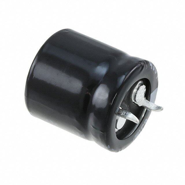
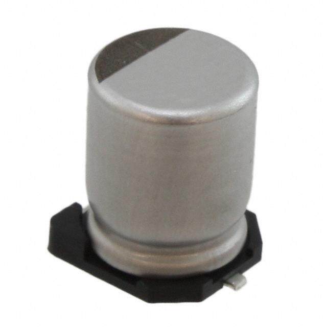
ICGOO电子元器件商城为您提供EDK476M035A9GAA由Kemet设计生产,在icgoo商城现货销售,并且可以通过原厂、代理商等渠道进行代购。 EDK476M035A9GAA价格参考。KemetEDK476M035A9GAA封装/规格:铝电解电容器, 47µF 35V 铝电解电容器 径向,Can - SMD 85°C 时为 2000 小时。您可以下载EDK476M035A9GAA参考资料、Datasheet数据手册功能说明书,资料中有EDK476M035A9GAA 详细功能的应用电路图电压和使用方法及教程。
KEMET的EDK476M035A9GAA是一款铝电解电容器,其主要应用场景包括但不限于以下几个方面:

1. 电源滤波:该型号电容器常用于开关电源(SMPS)、线性电源等电路中,作为输入或输出滤波电容。它能够有效抑制电源中的纹波电压,确保输出电压的稳定性。由于其容量较大(47µF),可以提供良好的低频滤波效果。

2. 直流支撑电容:在逆变器、电机驱动器等电力电子设备中,EDK476M035A9GAA可以用作直流支撑电容,帮助维持直流母线电压的稳定,尤其是在负载变化较大的情况下,防止电压波动对系统造成影响。

3. 音频设备:在音响功放、耳机放大器等音频设备中,这款电容器可以用于耦合和旁路电路,减少噪声干扰,提升音质表现。它的高耐压特性(35V)使其适用于多种工作环境。

4. 工业自动化:在工业控制系统、PLC模块等场合,该电容器可以用于平滑电源波动,保护敏感元件免受瞬态电压冲击的影响。此外,它还可以用于信号调理电路中,改善信号传输质量。

5. 消费电子产品:如电视机、显示器等消费类电子产品中,EDK476M035A9GAA可用于电源管理部分,确保设备在各种使用条件下都能获得稳定的供电。同时,它的小尺寸设计也有助于节省空间,满足现代电子产品紧凑化的需求。

6. 汽车电子:尽管该型号的工作温度范围为-55°C至+85°C,但在某些非关键部位(如车内娱乐系统、照明控制等)仍然可以发挥作用,提供可靠的电容性能。

总之,KEMET的EDK476M035A9GAA凭借其稳定的性能、广泛的适用性和良好的性价比,在众多领域中都有广泛的应用前景。
| 参数 | 数值 |
| 产品目录 | |
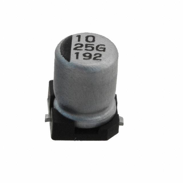
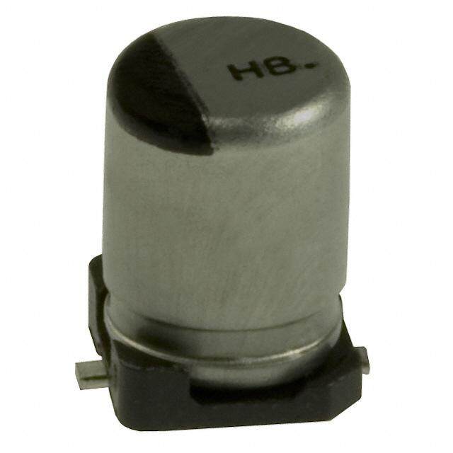
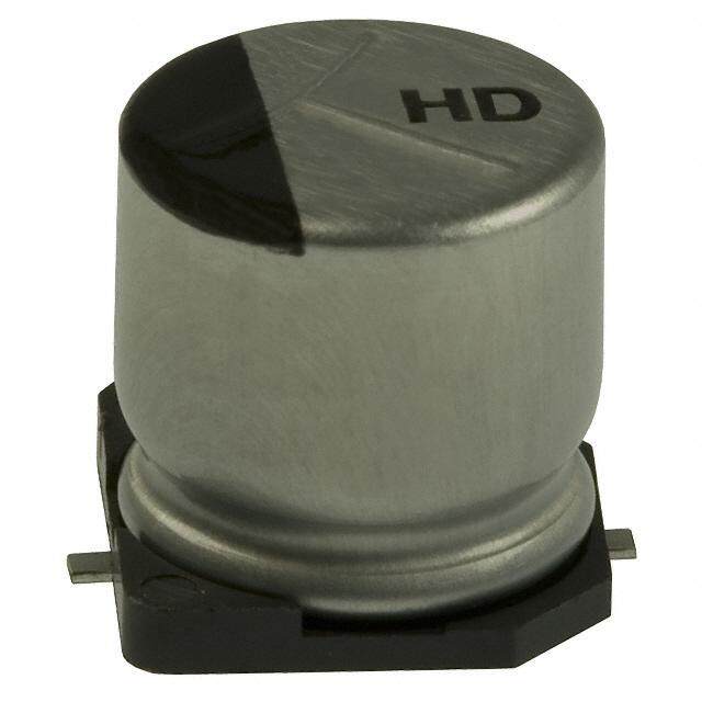
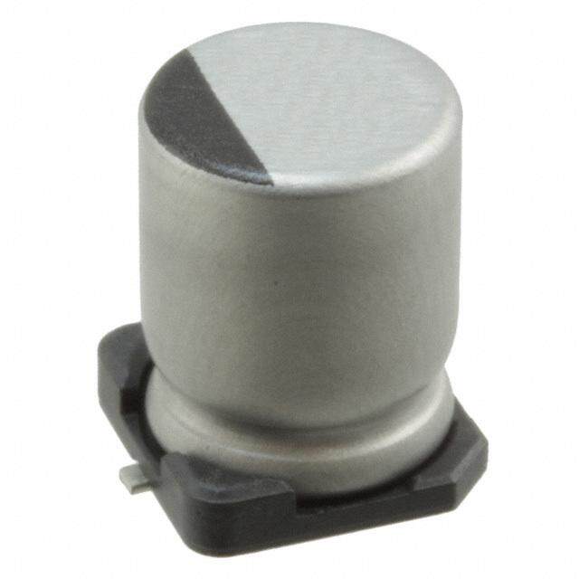
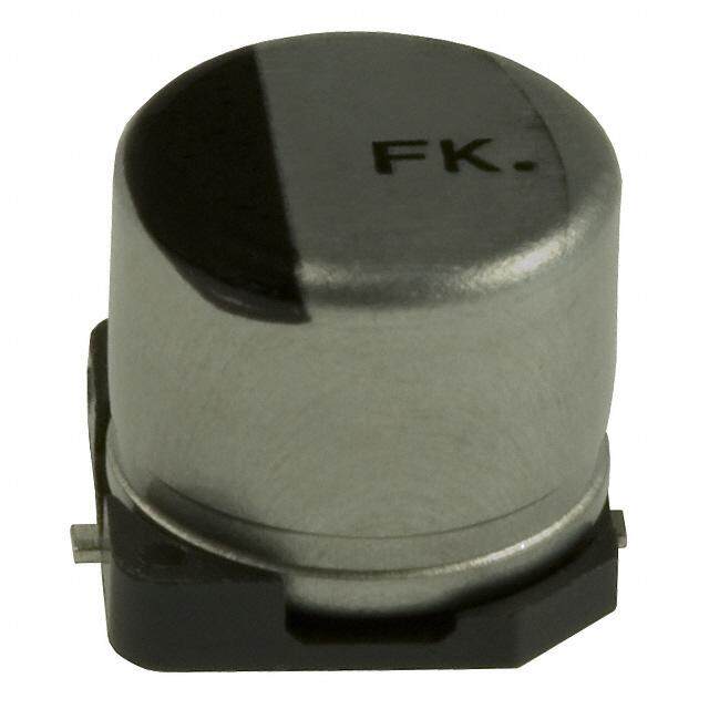
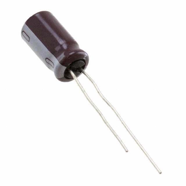
| 描述 | CAP ALUM 47UF 35V 20% SMD铝质电解电容器-SMD 47uF 35V 20% 85C SMD 6.3x5.4 |
| ESR(等效串联电阻) | - |
| 产品分类 | |
| 品牌 | Kemet |
| 产品手册 | http://www.kemet.com/docfinder?Partnumber=EDK476M035A9GAA |
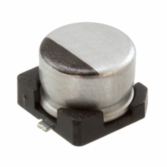
| 产品图片 |
|
| rohs | 符合RoHS无铅 / 符合限制有害物质指令(RoHS)规范要求 |
| 产品系列 | 铝电解电容器,铝质电解电容器-SMD,Kemet EDK476M035A9GAAEDK |
| 数据手册 | http://www.kemet.com/docfinder?Partnumber=EDK476M035A9GAA |
| 产品型号 | EDK476M035A9GAA |
| 不同温度时的使用寿命 | 85°C 时为 2000 小时 |
| 产品 | Aluminum Electrolytic Capacitors |
| 产品培训模块 | http://www.digikey.cn/PTM/IndividualPTM.page?site=cn&lang=zhs&ptm=25569http://www.digikey.cn/PTM/IndividualPTM.page?site=cn&lang=zhs&ptm=26047 |
| 产品种类 | 铝质电解电容器-SMD |
| 其它名称 | 399-6689-1 |
| 包装 | 剪切带 (CT) |
| 商标 | Kemet |
| 外壳直径 | 6.3 mm |
| 外壳长度 | 5.5 mm |
| 大小/尺寸 | 0.248" 直径(6.30mm) |
| 安装类型 | 表面贴装 |
| 容差 | ±20% |
| 封装 | Reel |
| 封装/外壳 | 径向,Can - SMD |
| 工作温度 | -40°C ~ 85°C |
| 工厂包装数量 | 1000 |
| 应用 | 通用 |
| 引线间距 | - |
| 最大工作温度 | + 85 C |
| 最小工作温度 | - 40 C |
| 标准包装 | 1 |
| 电压额定值DC | 35 V |
| 电容 | 47µF |
| 端接类型 | SMD/SMT |
| 类型 | - |
| 系列 | EDK |
| 纹波电流 | 135mA |
| 表面贴装焊盘尺寸 | 0.260" 长 x 0.307" 宽(6.60mm x 7.80mm) |
| 阻抗 | - |
| 零件号别名 | DK476M035A9GAAKPLP |
| 额定电压 | 35V |
| 高度-安装(最大值) | 0.222"(5.64mm) |


- 商务部:美国ITC正式对集成电路等产品启动337调查
- 曝三星4nm工艺存在良率问题 高通将骁龙8 Gen1或转产台积电
- 太阳诱电将投资9.5亿元在常州建新厂生产MLCC 预计2023年完工
- 英特尔发布欧洲新工厂建设计划 深化IDM 2.0 战略
- 台积电先进制程称霸业界 有大客户加持明年业绩稳了
- 达到5530亿美元!SIA预计今年全球半导体销售额将创下新高
- 英特尔拟将自动驾驶子公司Mobileye上市 估值或超500亿美元
- 三星加码芯片和SET,合并消费电子和移动部门,撤换高东真等 CEO
- 三星电子宣布重大人事变动 还合并消费电子和移动部门
- 海关总署:前11个月进口集成电路产品价值2.52万亿元 增长14.8%


PDF Datasheet 数据手册内容提取
Surface Mount Aluminum Electrolytic Capacitors EDK, +85°C Overview Applications The KEMET EDK aluminum electrolytic surface mount Typical applications include coupling, decoupling, bypass, capacitors are designed for high density printed circuit and filtering. boards. Benefits • Surface mount lead terminals • Low profile vertical chip • General purpose • 85°C/2,000 hours Part Number System EDK 336 M 004 A 9B AA Capacitance Rated Voltage Electrical Series Tolerance Size Code Packaging Code (pF) (VDC) Parameters Surface Mount First two digits M = ±20% 004 = 4.0 035 = 35 A = Standard See Dimension AA = Tape & Aluminum represent 6R3 = 6.3 050 = 50 S = AEC–Q200 Table Reel Electrolytic significant 010 = 10.0 063 = 63 figures for 016 = 16.0 100 = 100 capacitance 025 = 25.0 values. Last digit specifies the number of zeros to be added. One world. One KEMET © KEMET Electronics Corporation • KEMET Tower • One East Broward Boulevard A4001_EDK • 7/31/2019 1 Fort Lauderdale, FL 33301 USA • 954-766-2800 • www.kemet.com
Surface Mount Aluminum Electrolytic Capacitors – EDK, +85°C Dimensions – Millimeters C D G P B L A W F E E D L A/B C E Size Code Nominal Tolerance Nominal Tolerance Nominal Tolerance Nominal Tolerance Nominal Tolerance 9B 4.0 ±0.5 5.4 +0.25/−0.1 4.3 ±0.2 5.5 Maximum 1.8 ±0.2 9D 5.0 ±0.5 5.4 +0.25/−0.1 5.3 ±0.2 6.5 Maximum 2.2 ±0.2 9G 6.3 ±0.5 5.4 +0.25/−0.1 6.6 ±0.2 7.8 Maximum 2.6 ±0.2 9H 6.3 ±0.5 7.7 ±0.3 6.6 ±0.2 7.8 Maximum 2.6 ±0.2 9M 8.0 ±0.5 10.2 ±0.3 8.3 ±0.2 10.0 Maximum 3.4 ±0.2 9P 10.0 ±0.5 10.2 ±0.3 10.3 ±0.2 13.0 Maximum 3.5 ±0.2 9R 12.5 ±0.5 13.5 ±0.5 12.8 ±0.2 15.2 Maximum 4.9 ±0.2 9S 12.5 ±0.5 16.0 ±0.5 12.8 ±0.2 15.2 Maximum 4.9 ±0.2 F G P W Size Code Nominal Tolerance Nominal Tolerance Nominal Tolerance Nominal Tolerance 9B 0.3 Maximum 0.35 +0.15/−0.2 1.0 ±0.2 0.65 ±0.1 9D 0.3 Maximum 0.35 +0.15/−0.2 1.5 ±0.2 0.65 ±0.1 9G 0.3 Maximum 0.35 +0.15/−0.2 1.8 ±0.2 0.65 ±0.1 9H 0.3 Maximum 0.35 +0.15/−0.2 1.8 ±0.2 0.65 ±0.1 9M 0.3 Maximum 0.70 ±0.2 3.1 ±0.2 0.90 ±0.2 9P 0.3 Maximum 0.70 ±0.2 4.6 ±0.2 0.90 ±0.2 9R 0.3 Maximum 1.0 ±0.2 4.6 ±0.2 1.25 ±0.2 9S 0.3 Maximum 1.0 ±0.2 4.6 ±0.2 1.25 ±0.2 © KEMET Electronics Corporation • KEMET Tower • One East Broward Boulevard A4001_EDK • 7/31/2019 2 Fort Lauderdale, FL 33301 USA • 954-766-2800 • www.kemet.com
Surface Mount Aluminum Electrolytic Capacitors – EDK, +85°C Environmental Compliance As an environmentally conscious company, KEMET is working continuously with improvements concerning the environmental effects of both our capacitors and their production. In Europe (RoHS Directive) and in some other geographical areas like China, legislation has been put in place to prevent the use of some hazardous materials, such as lead (Pb), in electronic equipment. All products in this catalog are produced to help our customers’ obligations to guarantee their products and fulfill these legislative requirements. The only material of concern in our products has been lead (Pb), which has been removed from all designs to fulfill the requirement of containing less than 0.1% of lead in any homogeneous material. KEMET will closely follow any changes in legislation world wide and make any necessary changes in its products, whenever needed. Some customer segments such as medical, military and automotive electronics may still require the use of lead in electrode coatings. To clarify the situation and distinguish products from each other, a special symbol is used on the packaging labels for RoHS compatible capacitors. Due to customer requirements, there may appear additional markings such as lead free (LF) or lead-free wires (LFW) on the label. Performance Characteristics Item Performance Characteristics Capacitance Range 1 – 1,500 µF Rated Voltage 4 – 100 VDC Operating Temperature −40°C to +85°C Capacitance Tolerance ±20% at 120 Hz/20°C Life Test 2,000 hours (see conditions in Test Method & Performance) I ≤ 0.01 CV or 3 µA, whichever is greater Leakage Current C = rated capacitance (µF), V = rated voltage (VDC). Voltage applied for 2 minutes at 20°C. Automotive version: Part number position 11 = "S" 5G maximum acceleration. Vibration applied in 3 directions Vibration Test Specifications (X, Y, and Z axis). 4-hour sessions at 10 – 2,000 Hz (Capacitor clamped by the body) Impedance Z Characteristics at 120 Hz Rated Voltage (VDC) 4 6.3 10 16 25 35 50 63 100 Z (−25°C)/Z (20°C) 7 4 3 2 2 2 2 2 2 Z (−40°C)/Z (20°C) 15 8 6 4 4 3 3 3 3 © KEMET Electronics Corporation • KEMET Tower • One East Broward Boulevard A4001_EDK • 7/31/2019 3 Fort Lauderdale, FL 33301 USA • 954-766-2800 • www.kemet.com
Surface Mount Aluminum Electrolytic Capacitors – EDK, +85°C Compensation Factor of Ripple Current (RC) vs. Frequency Rated Voltage (VDC) 60 Hz 120 Hz 1 kHz 10 kHz Coefficient 0.80 1.00 1.15 1.25 Test Method & Performance Conditions Load Life Test Shelf Life Test Temperature 85°C 85°C Test Duration 2,000 hours 1,000 hours Ripple Current Maximum ripple current specified at 120 Hz 85°C No ripple current applied The sum of DC voltage and the peak AC voltage Voltage No voltage applied must not exceed the rated voltage of the capacitor. Performance The following specifications will be satisfied when the capacitor is restored to 20°C: Capacitance Change Within ±20% of the initial value Dissipation Factor Does not exceed 200% of the specified value Leakage Current Does not exceed specified value Shelf Life The capacitance, ESR and impedance of a capacitor will not change significantly after extended storage periods, however, the leakage current will very slowly increase. KEMET's E aluminum electrolytic capacitors should not be stored in high temperatures or where there is a high level of humidity. The suitable storage condition for KEMET's E aluminum electrolytic capacitors is +5 to +35°C and less than 75% in relative humidity. KEMET's E aluminum electrolytic capacitors should not be stored in damp conditions such as water, saltwater spray or oil spray. KEMET's E aluminum electrolytic capacitors should not be stored in an environment full of hazardous gas (hydrogen sulphide, sulphurous acid gas, nitrous acid, chlorine gas, ammonium, etc.) KEMET's E aluminum electrolytic capacitors should not be stored under exposure to ozone, ultraviolet rays or radiation. If a capacitor has been stored for more than 18 months under these conditions and it shows increased leakage current, then a treatment by voltage application is recommended. Re-Age (Reforming) Procedure Apply the rated voltage to the capacitor at room temperature for a period of one hour, or until the leakage current has fallen to a steady value below the specified limit. During re-aging a maximum charging current of twice the specified leakage current or 5 mA, whichever is greater, is suggested. © KEMET Electronics Corporation • KEMET Tower • One East Broward Boulevard A4001_EDK • 7/31/2019 4 Fort Lauderdale, FL 33301 USA • 954-766-2800 • www.kemet.com
Surface Mount Aluminum Electrolytic Capacitors – EDK, +85°C Table 1 – Ratings & Part Number Reference Rated DF RC LC VDC Surge Capacitance Case Size 120 Hz 120 Hz 20°C VDC Part Number Voltage 120 Hz 20°C D x L (mm) 20°C 85°C 2 Minutes (µF) (tan δ %) (mA) (µA) 4 5 33 4 x 5.4 35 26 3.0 EDK336M004(1)9BAA 4 5 47 4 x 5.4 35 34 3.0 EDK476M004(1)9BAA 4 5 100 5 x 5.4 35 61 4.0 EDK107M004(1)9DAA 4 5 220 6.3 x 5.4 35 82 8.8 EDK227M004(1)9GAA 4 5 330 6.3 x 5.4 35 80 13.2 EDK337M004(1)9GAA 4 5 470 6.3 x 7.7 35 200 18.8 EDK477M004(1)9HAA 6.3 8 22 4 x 5.4 26 20 3.0 EDK226M6R3(1)9BAA 6.3 8 33 5 x 5.4 26 22 3.0 EDK336M6R3(1)9DAA 6.3 8 33 4 x 5.4 26 22 3.0 EDK336M6R3(1)9BAA 6.3 8 47 4 x 5.4 26 36 3.0 EDK476M6R3(1)9BAA 6.3 8 47 5 x 5.4 26 46 3.0 EDK476M6R3(1)9DAA 6.3 8 100 5 x 5.4 26 47 6.3 EDK107M6R3(1)9DAA 6.3 8 100 6.3 x 5.4 26 71 6.3 EDK107M6R3(1)9GAA 6.3 8 150 6.3 x 5.4 26 71 9.5 EDK157M6R3(1)9GAA 6.3 8 220 8 x 6.2 35 250 13.9 EDK227M6R3(1)9LAA 6.3 8 220 6.3 x 5.4 35 74 13.9 EDK227M6R3(1)9GAA 6.3 8 220 6.3 x 7.7 35 235 13.9 EDK227M6R3(1)9HAA 6.3 8 330 8 x 6.2 35 300 20.8 EDK337M6R3(1)9LAA 6.3 8 330 6.3 x 7.7 35 280 20.8 EDK337M6R3(1)9HAA 6.3 8 470 8 x 10.2 35 380 29.6 EDK477M6R3(1)9MAA 6.3 8 680 10 x 10.2 35 458 42.8 EDK687M6R3(1)9PAA 6.3 8 1000 8 x 10.2 35 500 63.0 EDK108M6R3(1)9MAA 6.3 8 1000 10 x 10.2 35 700 63.0 EDK108M6R3(1)9PAA 6.3 8 1500 10 x 10.2 35 750 94.5 EDK158M6R3(1)9PAA 10 13 22 4 x 5.4 30 28 3.0 EDK226M010(1)9BAA 10 13 33 4 x 5.4 30 29 3.3 EDK336M010(1)9BAA 10 13 33 5 x 5.4 20 43 3.3 EDK336M010(1)9DAA 10 13 47 5 x 5.4 30 43 4.7 EDK476M010(1)9DAA 10 13 100 6.3 x 5.4 26 70 10.0 EDK107M010(1)9GAA 10 13 220 6.3 x 7.7 26 250 22.0 EDK227M010(1)9HAA 10 13 330 8 x 10.2 26 330 33.0 EDK337M010(1)9MAA 10 13 470 8 x 10.2 26 390 47.0 EDK477M010(1)9MAA 10 13 470 10 x 10.2 26 400 47.0 EDK477M010(1)9PAA 10 13 1000 10 x 10.2 26 580 100.0 EDK108M010(1)9PAA 16 20 4.7 4 x 5.4 16 20 3.0 EDK475M016(1)9BAA 16 20 10 4 x 5.4 16 28 3.0 EDK106M016(1)9BAA 16 20 22 5 x 5.4 16 39 3.5 EDK226M016(1)9DAA 16 20 22 4 x 5.4 26 28 3.5 EDK226M016(1)9BAA 16 20 22 5 x 5.4 16 39 3.5 EDK226M016(1)9DAA 16 20 33 5 x 5.4 26 45 5.3 EDK336M016(1)9DAA 16 20 33 6.3 x 5.4 16 66 5.3 EDK336M016(1)9GAA 16 20 47 5 x 5.4 16 45 7.5 EDK476M016(1)9DAA 16 20 47 6.3 x 5.4 16 70 7.5 EDK476M016(1)9GAA 16 20 100 6.3 x 5.4 20 70 16.0 EDK107M016(1)9GAA 16 20 100 6.3 x 7.7 20 85 16.0 EDK107M016(1)9HAA 16 20 220 6.3 x 7.7 20 162 35.2 EDK227M016(1)9HAA 16 20 220 8 x 10.2 20 280 35.2 EDK227M016(1)9MAA 16 20 330 8 x 10.2 20 320 52.8 EDK337M016(1)9MAA 16 20 330 10 x 10.2 20 380 52.8 EDK337M016(1)9PAA 16 20 470 8 x 10.2 20 350 75.2 EDK477M016(1)9MAA 16 20 470 10 x 10.2 20 420 75.2 EDK477M016(1)9PAA 16 20 680 10 x 10.2 20 430 108.8 EDK687M016(1)9PAA VDC VDC Surge Rated Capacitance Case Size DF RC LC Part Number (1) Insert Electrical Parameters code. See Part Number System for available options. © KEMET Electronics Corporation • KEMET Tower • One East Broward Boulevard A4001_EDK • 7/31/2019 5 Fort Lauderdale, FL 33301 USA • 954-766-2800 • www.kemet.com
Surface Mount Aluminum Electrolytic Capacitors – EDK, +85°C Table 1 – Ratings & Part Number Reference cont. Rated DF RC LC VDC Surge Capacitance Case Size 120 Hz 120 Hz 20°C VDC Part Number Voltage 120 Hz 20°C D x L (mm) 20°C 85°C 2 Minutes (µF) (tan δ %) (mA) (µA) 25 32 4.7 4 x 5.4 14 22 3.0 EDK475M025(1)9BAA 25 32 10 4 x 5.4 20 24 3.0 EDK106M025(1)9BAA 25 32 10 5 x 5.4 14 28 3.0 EDK106M025(1)9DAA 25 32 22 5 x 5.4 20 35 5.5 EDK226M025(1)9DAA 25 32 22 6.3 x 5.4 14 55 5.5 EDK226M025(1)9GAA 25 32 33 5 x 5.4 20 42 8.3 EDK336M025(1)9DAA 25 32 33 6.3 x 5.4 14 65 8.3 EDK336M025(1)9GAA 25 32 47 6.3 x 5.4 20 70 11.8 EDK476M025(1)9GAA 25 32 47 6.3 x 7.7 16 96 11.8 EDK476M025(1)9HAA 25 32 100 8 x 6.2 16 145 25.0 EDK107M025(1)9LAA 25 32 100 6.3 x 7.7 16 143 25.0 EDK107M025(1)9HAA 25 32 100 8 x 10.2 16 180 25.0 EDK107M025(1)9MAA 25 32 220 8 x 10.2 16 230 55.0 EDK227M025(1)9MAA 25 32 220 10 x 10.2 16 310 55.0 EDK227M025(1)9PAA 25 32 330 8 x 10.2 16 270 82.5 EDK337M025(1)9MAA 25 32 330 10 x 10.2 16 340 82.5 EDK337M025(1)9PAA 25 32 470 10 x 10.2 16 380 117.5 EDK477M025(1)9PAA 35 44 2.2 4 x 5.4 12 8 3.0 EDK225M035(1)9BAA 35 44 3.3 4 x 5.4 12 10 3.0 EDK335M035(1)9BAA 35 44 4.7 4 x 5.4 12 22 3.0 EDK475M035(1)9BAA 35 44 10 4 x 5.4 16 24 3.5 EDK106M035(1)9BAA 35 44 10 5 x 5.4 12 30 3.5 EDK106M035(1)9DAA 35 44 22 5 x 5.4 16 36 7.7 EDK226M035(1)9DAA 35 44 22 6.3 x 5.4 12 60 7.7 EDK226M035(1)9GAA 35 44 33 6.3 x 5.4 16 60 11.6 EDK336M035(1)9GAA 35 44 33 6.3 x 7.7 14 130 11.6 EDK336M035(1)9HAA 35 44 47 6.3 x 5.4 16 70 16.5 EDK476M035(1)9GAA 35 44 47 6.3 x 7.7 14 165 16.5 EDK476M035(1)9HAA 35 44 100 6.3 x 7.7 14 140 35.0 EDK107M035(1)9HAA 35 44 100 8 x 10.2 14 180 35.0 EDK107M035(1)9MAA 35 44 220 8 x 10.2 14 200 77.0 EDK227M035(1)9MAA 35 44 220 10 x 10.2 14 310 77.0 EDK227M035(1)9PAA 35 44 330 10 x 10.2 14 350 115.5 EDK337M035(1)9PAA 50 63 1 4 x 5.4 12 10 3.0 EDK105M050(1)9BAA 50 63 2.2 4 x 5.4 12 16 3.0 EDK225M050(1)9BAA 50 63 3.3 4 x 5.4 12 16 3.0 EDK335M050(1)9BAA 50 63 4.7 4 x 5.4 14 18 3.0 EDK475M050(1)9BAA 50 63 4.7 5 x 5.4 12 23 3.0 EDK475M050(1)9DAA 50 63 10 5 x 5.4 14 27 5.0 EDK106M050(1)9DAA 50 63 10 6.3 x 5.4 12 35 5.0 EDK106M050(1)9GAA 50 63 22 8 x 6.2 12 110 11.0 EDK226M050(1)9LAA 50 63 22 6.3 x 5.4 14 40 11.0 EDK226M050(1)9GAA 50 63 22 6.3 x 7.7 12 90 11.0 EDK226M050(1)9HAA 50 63 33 6.3 x 7.7 12 90 16.5 EDK336M050(1)9HAA 50 63 33 8 x 10.2 12 120 16.5 EDK336M050(1)9MAA 50 63 47 6.3 x 7.7 12 90 23.5 EDK476M050(1)9HAA 50 63 47 8 x 10.2 12 120 23.5 EDK476M050(1)9MAA 50 63 100 8 x 10.2 12 200 50.0 EDK107M050(1)9MAA 50 63 100 10 x 10.2 12 250 50.0 EDK107M050(1)9PAA 50 63 220 10 x 10.2 12 300 110.0 EDK227M050(1)9PAA 63 79 1 4 x 5.4 18 10 3.0 EDK105M063(1)9BAA VDC VDC Surge Rated Capacitance Case Size DF RC LC Part Number (1) Insert Electrical Parameters code. See Part Number System for available options. © KEMET Electronics Corporation • KEMET Tower • One East Broward Boulevard A4001_EDK • 7/31/2019 6 Fort Lauderdale, FL 33301 USA • 954-766-2800 • www.kemet.com
Surface Mount Aluminum Electrolytic Capacitors – EDK, +85°C Table 1 – Ratings & Part Number Reference cont. Rated DF RC LC VDC Surge Capacitance Case Size 120 Hz 120 Hz 20°C VDC Part Number Voltage 120 Hz 20°C D x L (mm) 20°C 85°C 2 Minutes (µF) (tan δ %) (mA) (µA) 63 79 4.7 6.3 x 5.4 18 20 3.0 EDK475M063(1)9GAA 63 79 10 8 x 10.2 18 30 6.3 EDK106M063(1)9MAA 63 79 10 6.3 x 5.4 18 20 6.3 EDK106M063(1)9GAA 63 79 22 6.3 x 7.7 18 40 13.9 EDK226M063(1)9HAA 63 79 22 8 x 10.2 18 40 13.9 EDK226M063(1)9MAA 63 79 33 8 x 10.2 18 45 20.8 EDK336M063(1)9MAA 63 79 47 8 x 10.2 18 45 29.6 EDK476M063(1)9MAA 63 79 100 10 x 10.2 18 60 63.0 EDK107M063(1)9PAA 100 125 2.2 6.3 x 5.4 18 30 3.0 EDK225M100(1)9GAA 100 125 3.3 6.3 x 7.7 18 50 3.3 EDK335M100(1)9HAA 100 125 4.7 8 x 10.2 18 50 4.7 EDK475M100(1)9MAA 100 125 4.7 6.3 x 7.7 18 50 4.7 EDK475M100(1)9HAA 100 125 10 6.3 x 7.7 18 50 10.0 EDK106M100(1)9HAA 100 125 10 8 x 10.2 18 55 10.0 EDK106M100(1)9MAA 100 125 22 8 x 10.2 18 55 22.0 EDK226M100(1)9MAA 100 125 22 10 x 10.2 18 85 22.0 EDK226M100(1)9PAA 100 125 33 10 x 10.2 18 90 33.0 EDK336M100(1)9PAA VDC VDC Surge Rated Capacitance Case Size DF RC LC Part Number (1) Insert Electrical Parameters code. See Part Number System for available options. © KEMET Electronics Corporation • KEMET Tower • One East Broward Boulevard A4001_EDK • 7/31/2019 7 Fort Lauderdale, FL 33301 USA • 954-766-2800 • www.kemet.com
Surface Mount Aluminum Electrolytic Capacitors – EDK, +85°C Mounting Positions (Safety Vent) In operation, electrolytic capacitors will always conduct a leakage current, which causes electrolysis. The oxygen produced by electrolysis will regenerate the dielectric layer but, at the same time, the hydrogen released may cause the internal pressure of the capacitor to increase. The overpressure vent, or safety vent, ensures that the gas can escape when the pressure reaches a certain value. All mounting positions must allow the safety vent to work properly. Installing • As a general principle, lower-use temperatures result in a longer, useful life of the capacitor. For this reason, it should be ensured that electrolytic capacitors are placed away from heat-emitting components. Adequate space should be allowed between components for cooling air to circulate, particularly when high ripple current loads are applied. In any case, the maximum category temperature must not be exceeded. • Do not deform the case of the capacitors or use capacitors with a deformed case. • Verify that the connections of the capacitors are able to insert on the board without excessive mechanical force. • If the capacitors require mounting through additional means, the recommended mounting accessories shall be used. • Verify the correct polarization of the capacitor on the board. • Verify that the space around the pressure relief device is according to the following guideline: Case Diameter Space Around Safety Vent ≤ 16 mm > 2 mm > 16 to ≤ 40 mm > 3 mm > 40 mm > 5 mm It is recommended that capacitors always be mounted with the safety device uppermost or in the upper part of the capacitor. • If the capacitors are stored for a long time, the leakage current must be verifi ed. If the leakage current is superior to the value listed in this catalog, the capacitors must be reformed. In this case, they can be reformed by application of the rated voltage through a series resistor approximately 1 kΩ for capacitors with V ≤ 160 V (5 W resistor) and 10 kΩ for the other R rated voltages. • In the case of capacitors connected in a series, a suitable voltage sharing must be used. In the case of balancing resistors, the approximate resistance value can be calculated as: R = 60/C. KEMET recommends, nevertheless, to ensure that the voltage across each capacitor does not exceed its rated voltage. © KEMET Electronics Corporation • KEMET Tower • One East Broward Boulevard A4001_EDK • 7/31/2019 8 Fort Lauderdale, FL 33301 USA • 954-766-2800 • www.kemet.com
Surface Mount Aluminum Electrolytic Capacitors – EDK, +85°C Application and Operation Guidelines Electrical Ratings: Capacitance (ESC) Simplifi ed equivalent circuit diagram of an electrolytic capacitor The capacitive component of the equivalent series circuit, (equivalent series capacitance - ESC), is determined by applying an alternate voltage of ≤ 0.5 V at a frequency of 120 or 100 Hz and 20°C (IEC 384-1, 384-4). Temperature Dependence of the Capacitance Capacitance of an electrolytic capacitor depends upon temperature: with decreasing temperature the viscosity of the electrolyte increases, thereby reducing its conductivity. Capacitance will decrease if temperature decreases. Furthermore, temperature drifts cause armature dilatation and, therefore, capacitance changes (up to 20% depending on the series considered, from 0 to 80°C). This phenomenon is more evident for electrolytic capacitors than for other types. Frequency Dependence of the Capacitance Effective capacitance value is derived from the impedance curve, as long as impedance is still in the range where the capacitance component is dominant. 1 C = capacitance (F) C = 2π fZ f = frequency (Hz) Z = impedance (Ω) Dissipation Factor tan δ (DF) Dissipation Factor tan δ is the ratio between the active and reactive power for a sinusoidal waveform voltage. It can be thought of as a measurement of the gap between an actual and ideal capacitor. reactive δ ideal actual active Tan δ is measured with the same set-up used for the series capacitance ESC. Tan δ = ω x ESC x ESR where: ESC = Equivalent series capacitance ESR = Equivalent series resistance © KEMET Electronics Corporation • KEMET Tower • One East Broward Boulevard A4001_EDK • 7/31/2019 9 Fort Lauderdale, FL 33301 USA • 954-766-2800 • www.kemet.com
Surface Mount Aluminum Electrolytic Capacitors – EDK, +85°C Equivalent Series Inductance (ESL) Equivalent series inductance or self inductance results from the terminal confi guration and internal design of the capacitor. Capacitor Equivalent Internal Circuit Equivalent Equivalent Equivalent Series Series Series Capacitance Resistance Inductance (ESC) (ESR) (ESL) Co Re L Equivalent Series Resistance (ESR) Equivalent series resistance is the resistive component of the equivalent series circuit. ESR value depends on frequency and temperature, and is related to the tan δ by the following equation: Ce ESR = Equivalent series resistance (Ω) tan δ tan δ = Dissipation factor ESR = 2πf ESC ESC = Equivalent series capacitance (F) f = Frequency (Hz) Tolerance limits of the rated capacitance must be taken into account when calculating this value. Equivalent Capacitance Impedance (Z) Impedance of an electrolytic capacitor results from a circuit formed by the following individual equivalent series components: C R L o e C e C = Aluminum oxide capacitance (surface and thickness of the dielectric.) o R = Resistance of electrolyte and paper mixture (other resistances not depending on the frequency are not considered: tabs, e plates, etc.) C = Electrolyte soaked paper capacitance. e L = Inductive reactance of the capacitor winding and terminals. Impedance of an electrolytic capacitor is not a constant quantity that retains its value under all conditions; it changes depending on frequency and temperature. Impedance as a function of frequency (sinusoidal waveform) for a certain temperature can be represented as follows: © KEMET Electronics Corporation • KEMET Tower • One East Broward Boulevard A4001_EDK • 7/31/2019 10 Fort Lauderdale, FL 33301 USA • 954-766-2800 • www.kemet.com
C R L o e C e Surface Mount Aluminum Electrolytic Capacitors – EDK, +85°C Impedance (Z) cont. Z [ohm] 1,000 100 1/ωωωωCe 10 B Re ωL A 1 1/ωωωωCo C (cid:31) 0.1 0.1 1 10 100 1,000 10,000 F [KHz] • Capacitive reactance predominates at low frequencies. • With increasing frequency, capacitive reactance Xc = 1/ωC decreases until it reaches the order of magnitude of o electrolyte resistance R (A) e • At even higher frequencies, resistance of the electrolyte predominates: Z = R (A - B) e • When the capacitor’s resonance frequency is reached (ω ), capacitive and inductive reactance mutually cancel each other 0 1/ωC = ωL, ω = 1/SQR(LC ) e 0 e • Above this frequency, inductive reactance of the winding and its terminals (XL = Z = ωL) becomes effective and leads to an increase in impedance Generally speaking, it can be estimated that C ≈ 0.01 C . e o Impedance as a function of frequency (sinusoidal waveform) for different temperature values can be represented as follows (typical values): Z (ohm) 10 µF 1,000 100 -40°C 10 20°C 85°C 1 0.1 0.1 1 10 100 1,000 10,000 F (KHz) R is the most temperature-dependent component of an electrolytic capacitor equivalent circuit. Electrolyte resistivity will e decrease if temperature rises. In order to obtain a low impedance value throughout the temperature range, R must be as little as possible. However, R e e values that are too low indicate a very aggressive electrolyte, resulting in a shorter life of the electrolytic capacitor at high temperatures. A compromise must be reached. © KEMET Electronics Corporation • KEMET Tower • One East Broward Boulevard A4001_EDK • 7/31/2019 11 Fort Lauderdale, FL 33301 USA • 954-766-2800 • www.kemet.com
Surface Mount Aluminum Electrolytic Capacitors – EDK, +85°C Leakage Current (LC) Due to the aluminum oxide layer that serves as a dielectric, a small current will continue to fl ow even after a DC voltage has been applied for long periods. This current is called leakage current. A high leakage current fl ows after applying voltage to the capacitor then decreases in a few minutes, for example, after prolonged storage without any applied voltage. In the course of continuous operation, the leakage current will decrease and reach an almost constant value. After a voltage-free storage the oxide layer may deteriorate, especially at a high temperature. Since there are no leakage currents to transport oxygen ions to the anode, the oxide layer is not regenerated. The result is that a higher than normal leakage current will fl ow when voltage is applied after prolonged storage. As the oxide layer is regenerated in use, the leakage current will gradually decrease to its normal level. The relationship between the leakage current and voltage applied at constant temperature can be shown schematically as follows: I V V V V R S F Where: V = Forming voltage F If this level is exceeded, a large quantity of heat and gas will be generated and the capacitor could be damaged. V = Rated voltage R This level represents the top of the linear part of the curve. V = Surge voltage S This lies between V and V. The capacitor can be subjected to V for short periods only. R F S Electrolytic capacitors are subjected to a reforming process before acceptance testing. The purpose of this preconditioning is to ensure that the same initial conditions are maintained when comparing different products. Ripple Current (RC) The maximum ripple current value depends on: • Ambient temperature • Surface area of the capacitor (heat dissipation area) tan δ or ESR • Frequency The capacitor’s life depends on the thermal stress. © KEMET Electronics Corporation • KEMET Tower • One East Broward Boulevard A4001_EDK • 7/31/2019 12 Fort Lauderdale, FL 33301 USA • 954-766-2800 • www.kemet.com
Surface Mount Aluminum Electrolytic Capacitors – EDK, +85°C Frequency Dependence of the Ripple Current ESR and, thus, the tan δ depend on the frequency of the applied voltage. This indicates that the allowed ripple current is also a function of the frequency. Temperature Dependence of the Ripple Current The data sheet specifi es maximum ripple current at the upper category temperature for each capacitor. Expected Life Calculation Expected life depends on operating temperature according to the following formula: L = Lo x 2(To-T)/10 Where: L: Expected life Lo: Load life at a maximum permissible operating temperature T: Actual operating temperature To: Maximum permissible operating temperature This formula is applicable between 40°C and To. Expected Life Calculation Chart °) C e ( ur at er p m e T g n ati er p O al u ct A Expected life (h) © KEMET Electronics Corporation • KEMET Tower • One East Broward Boulevard A4001_EDK • 7/31/2019 13 Fort Lauderdale, FL 33301 USA • 954-766-2800 • www.kemet.com
Surface Mount Aluminum Electrolytic Capacitors – EDK, +85°C Packaging Quantities Box Quantity Size Code Diameter (mm) Length (mm) Reel Quantity (4 Reels per box) 9B 4.0 5.4 2,000 10,000 9D 5.0 5.4 1,000 10,000 9G 6.3 5.4 1,000 10,000 9H 6.3 7.7 1,000 10,000 9M 8.0 10.2 500 4,000 9P 10.0 10.2 500 4,000 9R 12.5 13.5 200 1,200 9S 12.5 16.0 200 1,200 Standard Marking for Surface Mount Types Negative Polarity Capacitance (µF) Black Row Rated Voltage (VDC) Series Identification* Date Code (YMM) * First letter represents the series Second letter -Blank or “A” = Standard Part “S” = Automotive version Note: 6.3 V rated voltage shall be marked as 6 V, but 6.3 V shall be assured. *Y = Year Code 0 1 2 3 4 5 6 7 8 9 Year 2010 2011 2012 2013 2014 2015 2016 2017 2018 2019 M = Month Code 1 2 3 4 5 6 7 8 9 A B C Month 1 2 3 4 5 6 7 8 9 10 11 12 *M = Manufacturing internal code Standard 2 3 1 4 5 6 7 8 9 A B C D E F G AEC–Q200 H I J K L M N O P Q R S T U V W X Y Z © KEMET Electronics Corporation • KEMET Tower • One East Broward Boulevard A4001_EDK • 7/31/2019 14 Fort Lauderdale, FL 33301 USA • 954-766-2800 • www.kemet.com
Surface Mount Aluminum Electrolytic Capacitors – EDK, +85°C Construction Aluminum Can Detailed Cross Section Lead Rubber Seal Terminal Tabs Terminal Tab Rubber Seal Margin Aluminum Can Paper Spacer Impregnated with Electrolyte (First Layer) Lead (+) Paper Spacer Impreg- nated with Electrolyte (Third Layer) Anode Aluminum Foil, Cathode Alumi- Etched, Covered with num Foil, Etched Aluminum Oxide Lead (−) (Fourth Layer) (Second Layer) © KEMET Electronics Corporation • KEMET Tower • One East Broward Boulevard A4001_EDK • 7/31/2019 15 Fort Lauderdale, FL 33301 USA • 954-766-2800 • www.kemet.com
Surface Mount Aluminum Electrolytic Capacitors – EDK, +85°C Soldering Process The soldering conditions should be within the specified conditions below: Do not dip the capacitor body into the melted solder. Flux should only be applied to the capacitor terminals. T3 ) C ° ( al n mi TT32 r e r t o cit a p Pre-heat T1 a c f o e r u at T0 r e p m e T Time (seconds) Vapor heat transfer systems are not recommended. The system should be thermal, such as infra-red radiation or hot blast Observe the soldering conditions as shown below. Do not exceed these limits and avoid repeated reflowing Reflow Soldering Lead-Free Reflow Soldering cont'd. Maximum Time Temperature Maximum Time Temperature (°C) Size (Seconds) (°C) (Seconds) 250 10 T0 20 – 140 60 T3 Φ4 ~ Φ5 (4 – 50 V) 260 5 Pre-heat 140 – 180 150 Φ6.3 ~ Φ10 (4 – 50 V) 250 5 T1 180 – 140 100 Φ4 ~ Φ10 (63 – 100 V) 250 5 T2 > 200 60 T3 230 20 Temperature Maximum Time Size (°C) (Seconds) Lead-Free Reflow Soldering Φ4 ~ Φ5 250 10 (4 – 50 V) 260 5 Maximum Time Temperature (°C) T3 Φ6.3 ~ Φ10 (Seconds) 250 5 (4 – 50 V) T0 20 – 160 60 Φ4 ~ Φ10 Pre-heat 160 – 190 120 (63 – 100 V) 250 5 T1 190 – 180 90 ≥ Φ12.5 250 5 T2 > 220 60 © KEMET Electronics Corporation • KEMET Tower • One East Broward Boulevard A4001_EDK • 7/31/2019 16 Fort Lauderdale, FL 33301 USA • 954-766-2800 • www.kemet.com
Surface Mount Aluminum Electrolytic Capacitors – EDK, +85°C Lead Taping & Packaging Reel Case Size (mm) D H W ±0.2 ±0.8 ±1.0 4 x 5.4 21 14 5 x 5.4 21 14 D H 6.3 x 5.4 21 18 6.3 x 5.8 21 18 380 6.3 x 7.7 21 18 8 x 6.2 21 18 8 x 10.2 21 26 10 x 10.2 21 26 W Taping for Automatic Insertion Machines Feedinghole Chippocket ØD t 0 1 P P E 2 0 A F W B t 2 P 1 Taperunningdirection Chipcomponent Dimensions (mm) W A B P P P F D E t t 0 1 2 0 1 2 Tolerance Nominal Nominal Nominal ±0.1 ±0.1 ±0.1 Nominal ±0.1 Nominal Nominal Nominal 4 x 5.4 12 4.7 4.7 4 8 2 5.5 1.5 1.75 0.4 5.8 5 x 5.4 12 5.7 5.7 4 12 2 5.5 1.5 1.75 0.4 5.8 6.3 x 5.4 16 7 7 4 12 2 7.5 1.5 1.75 0.4 5.8 6.3 x 7.7 16 7 7 4 12 2 7.5 1.5 1.75 0.4 5.8 8 x 6.2 16 8.7 8.7 4 12 2 7.5 1.5 1.75 0.4 6.8 8 x 10.2 24 8.7 8.7 4 16 2 11.5 1.5 1.75 0.4 11 10 x 10.2 24 10.7 10.7 4 16 2 11.5 1.5 1.75 0.4 11 12.5 x 13.5 32 13.4 13.4 4 24 2 14.2 1.5 1.75 0.5 14 12.5 x 16 32 13.4 13.4 4 24 2 14.2 1.5 1.75 0.5 17.5 16 x 16.5 44 17.5 17.5 4 28 2 20.2 1.5 1.75 0.5 17.5 © KEMET Electronics Corporation • KEMET Tower • One East Broward Boulevard A4001_EDK • 7/31/2019 17 Fort Lauderdale, FL 33301 USA • 954-766-2800 • www.kemet.com
Surface Mount Aluminum Electrolytic Capacitors – EDK, +85°C Construction Data The manufacturing process begins with the anode foil being electrochemically etched to increase the surface area and then “formed” to produce the aluminum oxide layer. Both the anode and Extended cathode cathode foils are then interleaved with absorbent paper and wound into a cylinder. During the winding process, aluminum tabs are Anode foil attached to each foil to provide the electrical contact. The deck, complete with terminals, is attached to the tabs and then Foil tabs folded down to rest on top of the winding. The complete winding is impregnated with electrolyte before being housed in a suitable container, usually an aluminum can, and sealed. Throughout the Tissues process, all materials inside the housing must be maintained at the highest purity and be compatible with the electrolyte. Cathode foil Each capacitor is aged and tested before being sleeved and packed. The purpose of aging is to repair any damage in the oxide layer Etching and thus reduce the leakage current to a very low level. Aging is normally carried out at the rated temperature of the capacitor and Forming is accomplished by applying voltage to the device while carefully controlling the supply current. The process may take several hours to complete. Winding Damage to the oxide layer can occur due to variety of reasons: Decking • Slitting of the anode foil after forming • Attaching the tabs to the anode foil • Minor mechanical damage caused during winding Impregnation A sample from each batch is taken by the quality department after completion of the production process. This sample size is controlled Assembly by the use of recognized sampling tables defi ned in BS 6001. Aging The following tests are applied and may be varied at the request of the customer. In this case the batch, or special procedure, will determine the course of action. Testing Electrical: Mechanical/Visual: • Leakage current • Overall dimensions Sleeving • Capacitance • Torque test of mounting stud • ESR • Print detail Packing • Impedance • Box labels • Tan Delta • Packaging, including packed quantity © KEMET Electronics Corporation • KEMET Tower • One East Broward Boulevard A4001_EDK • 7/31/2019 18 Fort Lauderdale, FL 33301 USA • 954-766-2800 • www.kemet.com
Surface Mount Aluminum Electrolytic Capacitors – EDK, +85°C KEMET Electronics Corporation Sales Offi ces For a complete list of our global sales offi ces, please visit www.kemet.com/sales. Disclaimer All product specifi cations, statements, information and data (collectively, the “Information”) in this datasheet are subject to change. The customer is responsible for checking and verifying the extent to which the Information contained in this publication is applicable to an order at the time the order is placed. All Information given herein is believed to be accurate and reliable, but it is presented without guarantee, warranty, or responsibility of any kind, expressed or implied. Statements of suitability for certain applications are based on KEMET Electronics Corporation’s (“KEMET”) knowledge of typical operating conditions for such applications, but are not intended to constitute – and KEMET specifi cally disclaims – any warranty concerning suitability for a specifi c customer application or use. The Information is intended for use only by customers who have the requisite experience and capability to determine the correct products for their application. Any technical advice inferred from this Information or otherwise provided by KEMET with reference to the use of KEMET’s products is given gratis, and KEMET assumes no obligation or liability for the advice given or results obtained. Although KEMET designs and manufactures its products to the most stringent quality and safety standards, given the current state of the art, isolated component failures may still occur. Accordingly, customer applications which require a high degree of reliability or safety should employ suitable designs or other safeguards (such as installation of protective circuitry or redundancies) in order to ensure that the failure of an electrical component does not result in a risk of personal injury or property damage. Although all product–related warnings, cautions and notes must be observed, the customer should not assume that all safety measures are indicted or that other measures may not be required. KEMET is a registered trademark of KEMET Electronics Corporation. © KEMET Electronics Corporation • KEMET Tower • One East Broward Boulevard A4001_EDK • 7/31/2019 19 Fort Lauderdale, FL 33301 USA • 954-766-2800 • www.kemet.com
Mouser Electronics Authorized Distributor Click to View Pricing, Inventory, Delivery & Lifecycle Information: K EMET: EDK106M016A9BAA EDK226M016A9DAA EDK106M050A9GAA EDK107M016A9GAA EDK106M025A9DAA EDK106M035A9DAA EDK107M004A9DAA EDK107M025A9HAA EDK107M035A9HAA EDK107M050A9MAA EDK107M063A9PAA EDK107M6R3A9GAA EDK226M004A9BAA EDK226M025A9GAA EDK226M050A9HAA EDK226M6R3A9BAA EDK227M016A9HAA EDK227M035A9MAA EDK227M050A9PAA EDK227M6R3A9HAA EDK335M035A9BAA EDK336M025A9GAA EDK336M035A9GAA EDK475M035A9BAA EDK475M050A9DAA EDK476M004A9BAA EDK476M035S9GAA EDK476M050A9HAA EDK477M016A9MAA EDK477M6R3A9MAA EDK687M016A9PAA EDK106M063A9GAA EDK476M016A9GAA EDK476M025A9GAA EDK476M035A9GAA EDK105M050A9BAA EDK106M025A9BAA EDK227M025A9MAA EDK476M063A9MAA EDK477M025A9PAA EDK226M035A9GAA EDK226M016A9BAA EDK106M100A9HAA EDK335M050A9BAA EDK225M050A9BAA EDK476M010A9DAA EDK226M025A9DAA EDK226M035A9DAA EDK226M100A9MAA EDK335M050S9BAA EDK336M035A9HAA EDK337M016S9MAA EDK106M016S9BAA EDK337M025S9MAA EDK476M004S9BAA EDK476M016S9DAA EDK476M016S9GAA EDK227M6R3A9GAA EDK336M050S9HAA EDK336M6R3S9BAA EDK337M016A9MAA EDK476M6R3S9DAA EDK477M016S9PAA EDK226M010A9BAA EDK226M100S9MAA EDK107M035S9HAA EDK227M004S9GAA EDK337M004A9GAA EDK226M100S9PAA EDK336M016A9GAA EDK106M035S9DAA EDK107M050S9MAA EDK158M6R3S9PAA EDK226M025S9GAA EDK227M004A9GAA EDK336M100A9PAA EDK337M035A9PAA EDK336M016S9GAA EDK475M100S9HAA EDK106M025S9DAA EDK336M010S9DAA EDK336M100S9PAA EDK337M6R3S9HAA EDK475M100A9HAA EDK108M6R3A9MAA EDK108M6R3A9PAA EDK475M025A9BAA EDK107M050A9PAA EDK227M035A9PAA EDK107M016S9GAA EDK107M016S9HAA EDK226M035S9GAA EDK475M025S9BAA EDK336M025S9DAA EDK476M025A9HAA EDK477M004A9HAA EDK477M010S9MAA EDK477M016S9MAA EDK475M016S9BAA EDK106M035A9BAA