
 Datasheet下载
- 型号: E48SP12020NRFA
- 制造商: DELTA PRODUCTS CORPORATION
- 库位|库存: xxxx|xxxx
- 要求:
| 数量阶梯 | 香港交货 | 国内含税 |
| +xxxx | $xxxx | ¥xxxx |
查看当月历史价格
查看今年历史价格
E48SP12020NRFA产品简介:
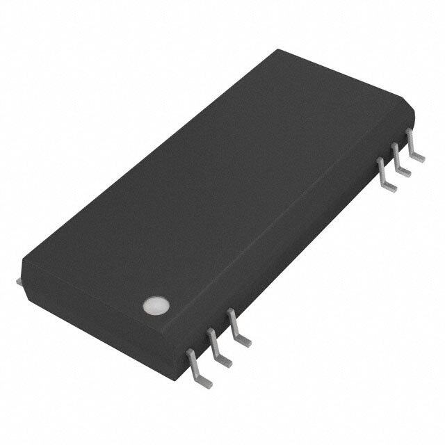
ICGOO电子元器件商城为您提供E48SP12020NRFA由DELTA PRODUCTS CORPORATION设计生产,在icgoo商城现货销售,并且可以通过原厂、代理商等渠道进行代购。 E48SP12020NRFA价格参考。DELTA PRODUCTS CORPORATIONE48SP12020NRFA封装/规格:直流转换器, 隔离模块 DC/DC 转换器 1 输出 12V 20A 36V - 75V 输入。您可以下载E48SP12020NRFA参考资料、Datasheet数据手册功能说明书,资料中有E48SP12020NRFA 详细功能的应用电路图电压和使用方法及教程。
Delta Electronics的直流转换器型号E48SP12020NRFA是一款高效、紧凑的电源转换模块,其主要应用场景如下:

1. 通信设备:该型号适用于基站、路由器和交换机等通信设备,为系统中的低电压组件提供稳定的直流电源。其高效率和小尺寸设计非常适合空间有限的通信环境。

2. 工业自动化:在工业控制领域,这款转换器可用于PLC(可编程逻辑控制器)、传感器和执行器的供电。它能够承受工业环境中常见的电压波动和电磁干扰,确保设备稳定运行。

3. 医疗设备:由于其高可靠性和安全性,E48SP12020NRFA也可用于某些非关键医疗设备,如监护仪或诊断设备的辅助电源,满足医疗行业对电源性能的严格要求。

4. 嵌入式系统:在嵌入式计算平台中,这款转换器为处理器、存储器和其他外围设备提供必要的电力支持。其高效的电能转换能力有助于降低系统功耗。

5. 新能源应用:在太阳能逆变器或风力发电系统中,该转换器可以作为辅助电源,为控制系统和监测单元供电,支持可再生能源的高效利用。

6. 交通运输:适用于轨道交通信号系统、车载电子设备等领域,提供可靠的直流电源,适应复杂的振动和温度变化环境。

总体而言,E48SP12020NRFA凭借其高效、紧凑和可靠的特点,广泛应用于需要稳定直流电源的各种场景,尤其是在对电源性能和空间要求较高的场合。
| 参数 | 数值 |
| 产品目录 | |
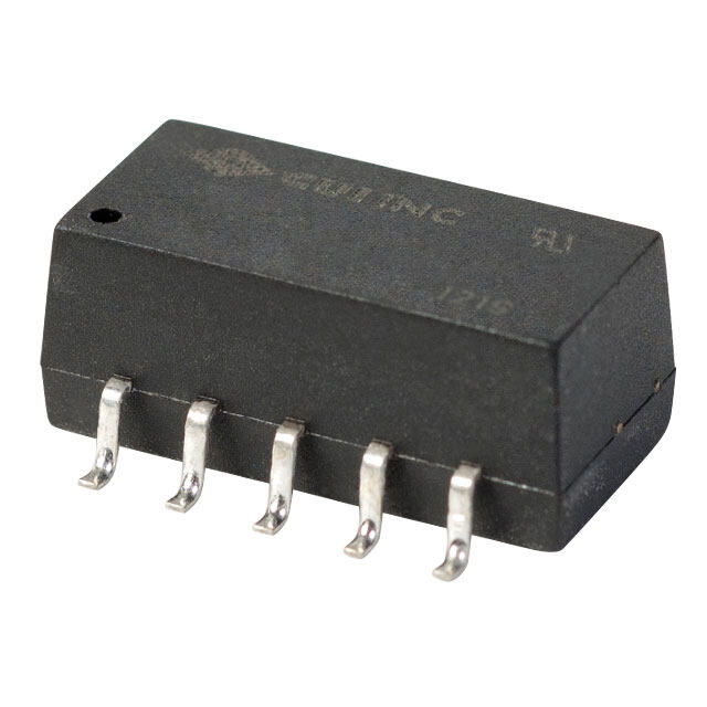
| 描述 | MODULE DC/DC 8TH BRICK 12V 20A |
| 产品分类 | DC DC Converters |
| 品牌 | Delta Electronics |
| 数据手册 | |
| 产品图片 |
|
| 产品型号 | E48SP12020NRFA |
| rohs | 无铅 / 符合限制有害物质指令(RoHS)规范要求 |
| 产品系列 | Delphi E48SP |
| 产品培训模块 | http://www.digikey.cn/PTM/IndividualPTM.page?site=cn&lang=zhs&ptm=26203http://www.digikey.cn/PTM/IndividualPTM.page?site=cn&lang=zhs&ptm=26207 |
| 其它名称 | 941-1053 |
| 功率(W)-制造系列 | 240W |
| 功率(W)-最大值 | 240W |
| 包装 | 托盘 |
| 大小/尺寸 | 2.30" 长 x 0.90" 宽 x 0.43" 高(58.4mm x 22.8mm x 10.9mm) |
| 安装类型 | 通孔 |
| 封装/外壳 | 5-DIP 模块,1/8 砖 |
| 工作温度 | -40°C ~ 122°C |
| 效率 | 94.5% |
| 标准包装 | 21 |
| 特性 | 远程开/关, OCP, OTP, OVP, UVLO |
| 特色产品 | http://www.digikey.cn/product-highlights/cn/zh/delta-power-mgmt-acdc-industrial/3751 |
| 电压-输入(最大值) | 75V |
| 电压-输入(最小值) | 36V |
| 电压-输出1 | 12V |
| 电压-输出2 | - |
| 电压-输出3 | - |
| 电压-隔离 | 2.25kV(2250V) |
| 电流-输出(最大值) | 20A |
| 相关产品 | /product-detail/zh/ATS-1186-C1-R0/ATS1494-ND/4146477/product-detail/zh/ATS-1184-C1-R0/ATS1493-ND/4146476/product-detail/zh/ATS-1183-C1-R0/ATS1492-ND/4146475/product-detail/zh/ATS-1181-C1-R0/ATS1491-ND/4146474/product-detail/zh/ATS-1179-C1-R0/ATS1512-ND/4146473/product-detail/zh/ATS-1178-C1-R0/ATS1489-ND/4146472 |
| 类型 | 隔离模块 |
| 输出数 | 1 |


- 商务部:美国ITC正式对集成电路等产品启动337调查
- 曝三星4nm工艺存在良率问题 高通将骁龙8 Gen1或转产台积电
- 太阳诱电将投资9.5亿元在常州建新厂生产MLCC 预计2023年完工
- 英特尔发布欧洲新工厂建设计划 深化IDM 2.0 战略
- 台积电先进制程称霸业界 有大客户加持明年业绩稳了
- 达到5530亿美元!SIA预计今年全球半导体销售额将创下新高
- 英特尔拟将自动驾驶子公司Mobileye上市 估值或超500亿美元
- 三星加码芯片和SET,合并消费电子和移动部门,撤换高东真等 CEO
- 三星电子宣布重大人事变动 还合并消费电子和移动部门
- 海关总署:前11个月进口集成电路产品价值2.52万亿元 增长14.8%


PDF Datasheet 数据手册内容提取
` FEATURES High efficiency: 94.5% @12V/20A Size: 58.4mm x 22.8mm x 10.9mm (2.30”x0.90”x0.43”) W/O Heat spreader 58.4mm x 22.8mm x 12.7mm (2.30”x0.90”x0.5”) With Heat spreader Industry standard pin out Fixed frequency operation Input UVLO, Output OCP & OVP, OTP Monotonic startup into normal and Pre-biased loads 2250V Isolation and basic insulation No minimum load required No negative current during power on or power off; ISO 9001, TL 9000, ISO 14001, QS 9000, OHSAS 18001 certified manufacturing facility UL/cUL 60950-1 (US & Canada) recognized. D elphi Series E48SP Eighth Brick Family D C/DC Power Modules: 48V in, 12V/20A out OPTIONS The Delphi Series E48SP, 36~75V input, Eighth Brick, single output, Positive On/Off logic isolated DC/DC converters are the latest offering from a world leader in Short pin lengths available power systems technology and manufacturing ― Delta Electronics, Latched over voltage protection In c. The E48SP product provides up to 240 watts of power in an industry standard footprint and pinout. The E48SP converter operates from an input voltage of 36V to 75V. Efficiency is 94.5% for the 12V output at full load. With creative design technology and o ptimization of component placement, these converters possess o utstanding electrical and thermal performance, as well as extremely high reliability under highly stressful operating conditions. All models are fully protected from abnormal input/output voltage, current, and APPLICATIONS temperature conditions. The Delphi Series converters meet all safety re quirements with basic insulation. Telecom/DataCom Wireless Networks Optical Network Equipment Server and Data Storage Industrial/Test Equipment DATASHEET DS_E48SP12020_06142017
TECHNICAL SPECIFICATIONS (T =25°C, airflow rate=300 LFM, V =48Vdc, nominal Vout unless otherwise noted.) A in PARAMETER NOTES and CONDITIONS E48SP12020 (Standard) Min. Typ. Max. Units ABSOLUTE MAXIMUM RATINGS Input Voltage Continuous 80 Vdc Transient (100ms) 100ms 100 Vdc Operating Hot Spot Temperature (Without heat spreader) Refer to figure 18 for measuring point -40 122 °C Operating Case Temperature (With heat spreader) Refer to figure 20 for measuring point -40 110 °C Storage Temperature -55 125 °C Input/Output Isolation Voltage 2250 Vdc INPUT CHARACTERISTICS Operating Input Voltage 36 75 Vdc Input Under-Voltage Lockout Turn-On Voltage Threshold 32.5 34 35.5 Vdc Turn-Off Voltage Threshold 30.5 32 33.5 Vdc Lockout Hysteresis Voltage 1 2 3 Vdc Maximum Input Current Vin=36V, 100% Load, 7 7.8 A No-Load Input Current 70 150 mA Off Converter Input Current 8 12 mA Inrush Current(I2t) With 100uF external input capacitor 1 A2s Start up Current Peak, Vin=36V, 100% Load, With 5000uF Co 7 12 A Input Terminal Ripple Current RMS, Vin=48V, With 100uF input cap. 0.16 0.24 A Input Reflected-Ripple Current P-P thru 12µH inductor, 5Hz to 20MHz 6 mA Input Voltage Ripple Rejection 120 Hz 60 dB OUTPUT CHARACTERISTICS Output Voltage Set Point Vin=48V, Io=Io.max, Tc=25°C 11.67 11.85 12.02 Vdc Output Voltage Regulation Over Load Io=Io,min to Io,max +20 mV Over Line Vin=36V to 75V +15 mV Over Temperature Tc=-40°C to 125°C ±120 mV Total Output Voltage Range over sample load, and temperature 11.5 11.85 12.2 V Output Voltage Ripple and Noise 5Hz to 20MHz bandwidth Peak-to-Peak Full Load, 1µF ceramic, 10µF tantalum 100 200 mV RMS Full Load, 1µF ceramic, 10µF tantalum 40 80 mV Operating Output Current Range Full input voltage range 0 20 A Output DC Current-Limit Inception Output Voltage 10% Low 110 150 % DYNAMIC CHARACTERISTICS Output Voltage Current Transient 48V, 10µF Tan & 1µF Ceramic load cap, 0.1A/µs Positive Step Change in Output Current 50% Io.max to 75% Io.max 200 400 mV Negative Step Change in Output Current 75% Io.max to 50% Io.max 200 400 mV Setting Time (within 1% Vout nominal) 200 µs Turn-On Transient Start-Up Time, From On/Off Control 30 40 ms Start-Up Time, From Input 30 40 ms Maximum Output Capacitance Full load; no overshoot of Vout at startup 5000 µF EFFICIENCY 100% Load Vin=48V 93.5 94.5 % 60% Load Vin=48V 94 95 % ISOLATION CHARACTERISTICS Input to Output 2250 Vdc Isolation Resistance 10 MΩ Isolation Capacitance 1500 pF FEATURE CHARACTERISTICS Switching Frequency 245 kHz ON/OFF Control, Negative Remote On/Off logic Logic Low (Module On) Von/off -0.7 0.8 V Logic High (Module Off) Von/off 2.4 50 V ON/OFF Control, Positive Remote On/Off logic Logic Low (Module Off) Von/off -0.7 0.8 V Logic High (Module On) Von/off 2.4 50 V ON/OFF Current (for both remote on/off logic) Ion/off at Von/off=0.0V 0.5 mA ON/OFF Current (for both remote on/off logic) Ion/off at Von/off=2.4V 10 µA Leakage Current (for both remote on/off logic) Logic High, Von/off=15V 50 µA Output Over-Voltage Protection Over full temp range; % of nominal Vout 14.6 18 V GENERAL SPECIFICATIONS MTBF Io=100% of Io, max; 300LFM; Ta=25°C 1.19 M hours Weight Open frame 29.1 grams Weight With heat spreader 39.2 grams Over-Temperature Shutdown ( Without heat spreader) Refer to figure 18 for measuring point 132 °C Over-Temperature Shutdown (With heat spreader) Refer to figure 20 for measuring point 120 °C 2 DS_E48SP12020_06142017
ELECTRICAL CHARACTERISTICS CURVES 96 20 95 18 94 16 93 14 36V Efficiency(%) 999012 4785VV Power Loss(W) 11802 347685VVV 89 6 88 4 87 2 86 0 2 4 6 8 10 12 14 16 18 20 0 2 4 6 8 10 12 14 16 18 20 Output Current(A) Output Current(A) Figure 1: Efficiency vs. load current for minimum, nominal, and Figure 2: Power dissipation vs. load current for minimum, nominal, maximum input voltage at 25°C and maximum input voltage at 25°C 8 15 7 12 6 5 V) A) ge( 9 urrent(4 ut Volta put c3 Outp 6 n I 2 3 1 0 0 30 32 34 3638 40 42 44 46 48 50 5254 56 58 60 62 64 66 6870 72 74 76 0 5 10 15 20 25 30 Output Current(A) Input voltage(V) Figure 3: Typical full load input characteristics at room Figure 4: Output voltage regulation vs load current showing typical temperature current limit curves and converter shutdown points for minimum, nominal, and maximum input voltag e at room temperature 3 DS_E48SP12020_06142017
ELECTRICAL CHARACTERISTICS CURVES For Negative Remote On/Off Logic Figure 5: Turn-on transient at zero load current (10ms/div). Figure 6: Turn-on transient at full rated load current (constant Vin=48V. Top Trace: Vout, 5V/di v; Bottom Trace: ON/OFF input, current load) (10 ms/div). Vin= 48V. Top Trace: Vout, 5V/div; 5V/div Bottom Trace: ON/OFF input, 5V/div For Input Voltage Start up Figure 7: Turn-on transient at zero load current (10 ms/div). Figure 8: Turn-on transient at full rated load current (constant Vin=48V. Top Trace: Vout, 5V/d iv, Bottom Trace: input voltage, current load) (10 ms/div). Vin= 48V. Top Trace: Vout, 5V/div; 30V/div Bottom Trace: input voltage, 30V/div 4 DS_E48SP12020_06142017
ELECTRICAL CHARACTERISTICS CURVES Figure 9: Output voltage response to step-change in load Figure 10: Output voltage response to step-change in load current (75%-50% of Io, max; d i/dt = 0.1A/µs, Vin=48V). Load current (50%-75% of Io, max; d i/dt = 0.1A/µs, Vin=48V). Load cap: 10µF, tantalum capacitor and 1µF ceramic capacitor. Top cap: 10µF, tantalum capacitor and 1µF ceramic capacitor. Top Trace: Vout (80mV/div, 200us/d iv); Bottom Trace: Io (10A/div, Trace: Vout (80mV/div, 200us/d iv); Bottom Trace: Io (10A/div, 200us/div). Scope measurement should be made using a BNC 200us/div). Scope measurement should be made using a BNC cable (length shorter than 20 inches). Position the load cable (length shorter than 20 inches). Position the load between 51 mm to 76 mm (2 inches to 3 inches) from the between 51 mm to 76 mm (2 inches to 3 inches) from the module.. module.. iiisss iiiccc VViinn++ ++++ ++++ VViinn-- CCCsss::: 222222000uuuFFF 111000000uuuFFF,,, EEESSSRRR===000...222 ooohhhmmm @@@ 222555oooCCC 111000000KKKHHHzzz Figure 11: Test set-up diagram showing measurement points Figure 12: Input Terminal Ripple Current, i , at full rated output c for Input Terminal Ripple Current and Input Reflected Ripple current and nominal input voltag e with 12µH source impedance Current. and 100µF electrolytic capacitor (200 mA/div, 2us/div). Note: Measured input reflected-ripple current with a simulated source Inductance (L ) of 12 μH. Capacitor Cs offset TEST possible battery impedance. Measure current as shown below 5 DS_E48SP12020_06142017
ELECTRICAL CHARACTERISTICS CURVES Copper Strip Vo(+) SCOPE RESISTIVE 10u 1u LOAD Vo(-) Figure 13: Input reflected ripple current, i , through a 12µH Figure 14: Output voltage noise and ripple measurement test s source inductor at nominal inpu t voltage and rated load current setup (20 mA/div, 2us/div). Figure 15: Output voltage ripple at nominal input voltage and rated load current (Io=20A)(20 m V/div, 2us/div) Load capacitance: 1µF ceramic capacitor and 10µF tantalum capacitor. Bandwidth: 20 MHz. Scope measurements should be made using a BNC cable (length shorter than 20 inches). Position the load between 51 mm to 76 mm (2 inches to 3 inches) from the module. 6 DS_E48SP12020_06142017
DESIGN CONSIDERATIONS Safety Considerations The power module must be installed in compliance with Input Source Impedance the spacing and separation requirements of the The impedance of the input source connecting to the end-user’s safety agency standard, i.e., UL60950-1, DC/DC power modules will interact with the modules and CAN/CSA-C22.2, No. 60950-1 and EN60950-1+A11 and affect the stability. A low ac-impedance input source is IEC60950-1, if the system in which the power module is recommended. If the source inductance is more than a to be used must meet safety agency requirements. few μH, we advise adding a 33 to 100 μF electrolytic Basic insulation based on 75 Vdc input is provided capacitor (ESR < 0.7 Ω at 100 kHz) mounted close to the between the input and output of the module for the input of the module to improve the stability. purpose of applying insulation requirements when the input to this DC-to-DC converter is identified as TNV-2 Layout and EMC Considerations or SELV. An additional evaluation is needed if the source is other than TNV-2 or SELV. Delta’s DC/DC power modules are designed to operate in When the input source is SELV circuit, the power module a wide variety of systems and applications. For design meets SELV (safety extra-low voltage) requirements. If assistance with EMC compliance and related PWB layout the input source is a hazardous voltage which is greater issues, please contact Delta’s technical support team. An than 60 Vdc and less than or equal to 75 Vdc, for the external input filter module is available for easier EMC module’s output to meet SELV requirements, all of the compliance design. Below is the reference design for an following must be met: input filter tested with E48SP12020XXXX to meet class B in CISSPR 22. The input source must be insulated from the ac mains by reinforced or double insulation. Schematic and Components List The input terminals of the module are not operator Vin(+) Vo(+) accessible. If the metal baseplate / heatspreader is grounded CY1 the output must be also grounded. Cin Vin CX E48SP12020 LOAD A SELV reliability test is conducted on the system L1 where the module is used, in combination with the CY2 module, to ensure that under a single fault, - Vin(-) Vo(-) hazardous voltage does not appear at the module’s output. CY When installed into a Class II equipment (without Cin is 100uF*2 low ESR Aluminum cap; grounding), spacing consideration should be given to CX is 2.2uF ceramic cap; the end-use installation, as the spacing between the CY1 are 10nF ceramic caps; module and mounting surface have not been evaluated. CY2 are 10nF ceramic caps; CY is 1nF ceramic cap; The power module has extra-low voltage (ELV) outputs L1 is common-mode inductor, L1=0.53mH; when all inputs are ELV. Test Result: Vin=48V, Io=20A, This power module is not internally fused. To achieve optimum safety and system protection, an input line fuse is highly recommended. The safety agencies require a Fast-acting fuse with 30A maximum rating to be installed in the ungrounded lead. A lower rated fuse can be used based on the maximum inrush transient energy and maximum input current. Soldering and Cleaning Considerations Post solder cleaning is usually the final board assembly process before the board or system undergoes electrical testing. Inadequate cleaning and/or drying may lower the reliability of a power module and severely affect the finished circuit board assembly test. Adequate cleaning and/or drying is especially important for un-encapsulated and/or open frame type power modules. For assistance Yellow line is quasi peak mode; Blue line is average mode. on appropriate soldering and cleaning procedures, please contact Delta’s technical support team. 7 DS_E48SP12020_06142017
FEATURES DESCRIPTIONS Over-Current Protection Remote On/Off The modules include an internal output over-current The remote on/off feature on the module can be either protection circuit, which will endure current limiting for negative or positive logic. Negative logic turns the module an unlimited duration during output overload. If the on during a logic low and off during a logic high. Positive output current exceeds the OCP set point, the modules logic turns the modules on during a logic high and off will automatically shut down, and enter hiccup mode or during a logic low. latch mode, which is optional. Remote on/off can be controlled by an external switch For hiccup mode, the module will try to restart after between the on/off terminal and the Vi(-) terminal. The shutdown. If the overload condition still exists, the switch can be an open collector or open drain. module will shut down again. This restart trial will continue until the overload condition is corrected. For negative logic if the remote on/off feature is not used, please short the on/off pin to Vi(-). For positive logic if the For latch mode, the module will latch off once it remote on/off feature is not used, please leave the on/off shutdown. The latch is reset by either cycling the input pin floating. power or by toggling the on/off signal for one second. The module will not response to the remote on/off signal Over-Voltage Protection which is less than 120us. The modules include an internal output over-voltage protection circuit, which monitors the voltage on the output terminals. If this voltage exceeds the over-voltage VVViii(((+++))) VVVooo(((+++))) set point, the module will shut down, and enter in hiccup mode or latch mode, which is optional. The default mode is hiccup mode. RR OOONNN///OOOFFFFFF LLooaadd For hiccup mode, the module will try to restart after shutdown. If the output overvoltage condition still exists, VVViii(((---))) VVVooo(((---))) the module will shut down again. This restart trial will continue until the over-voltage condition is corrected. For latch mode, the module will latch off once it Figure 16: Remote on/off implementation shutdown. The latch is reset by either cycling the input power or by toggling the on/off signal for one second. Over-Temperature Protection The over-temperature protection consists of circuitry that provides protection from thermal damage. If the temperature exceeds the over-temperature threshold the module will shut down, and enter in auto-restart mode or latch mode, which is optional. For auto-restart mode, the module will monitor the module temperature after shutdown. Once the temperature is dropped and within the specification, the module will be auto-restart. For latch mode, the module will latch off once it shutdown. The latch is reset by either cycling the input power or by toggling the on/off signal for one second. 8 DS_E48SP12020_06142017
THERMAL CONSIDERATIONS Thermal management is an important part of the system design. To ensure proper, reliable operation, sufficient cooling of the power module is needed over the entire temperature range of the module. Convection cooling is usually the dominant mode of heat transfer. Hence, the choice of equipment to characterize the thermal performance of the power module is a wind tunnel. Thermal Testing Setup Delta’s DC/DC power modules are characterized in heated vertical wind tunnels that simulate the thermal environments encountered in most electronics equipment. This type of equipment commonly uses vertically mounted circuit cards in cabinet racks in which the power modules are mounted. The following figure shows the wind tunnel characterization setup. The power module is mounted on a test PWB and is vertically positioned within the wind tunnel. The space between the neighboring PWB and the top of the power module is constantly kept at 6.35mm (0.25’’). FACING PWB PWB MODULE AIR VELOCITY AND AMBIENT TEMPERATURE MEASURED BELOW THE MODULE 50.8 (2.0”) AIR FLOW 12.7 (0.5”) Note: Wind Tunnel Test Setup Figure Dimensions are in millimeters and (Inches) Figure 17: Wind tunnel test setup Thermal Derating Heat can be removed by increasing airflow over the module. To enhance system reliability; the power module should always be operated below the maximum operating temperature. If the temperature exceeds the maximum module temperature, reliability of the unit may be affected. 9 DS_E48SP12020_06142017
THERMAL CURVES THERMAL CURVES (WITHOUT HEAT SPREADER) (WITH HEAT SPREADER) Figure 18: Temperature measurement location Figure 20: Temperature measurement location * The allowed maximum hot spot temperature is defined at 122℃ * The allowed maximum hot spot temperature is defined at 110℃ E48SP12020(Standard) Output Current vs. Ambient Temperature and Air Velocity Output Current (A)E48SP12020(Standard@) VOinu t=pu 4t8 CVu (rTrernatn svsve. rAsme bOierinetn Ttaetmiopne)rature and Air Velocity Output Current (A) @Vin = 48V (Transverse Orientation,With Heatspreader) 20 20 18 18 Natural Natural Convection 16 Convection 16 100LFM 14 100LFM 14 200LFM 12 200LFM 12 300LFM 10 300LFM 10 400LFM 8 8 400LFM 6 6 500LFM 500LFM 4 4 600LFM 600LFM 2 2 025 30 35 40 45 50 55 60 65 70 A7m5bient Tem8p0erature (℃85) 025 30 35 40 45 50 55 60 65 70 A7m5bient Tem8p0erature (℃85) Figure 19: Output current vs. ambient temperature and air Figure 21: Output current vs. ambient temperature and air velocity velocity @Vin=48V(Transverse Orientation, without heat @Vin=48V(Transverse Orientation, with heat spreader) spreader) 10 DS_E48SP12020_06142017
PICK AND PLACE LOCATION RECOMMENDED PAD LAYOUT (SMD) SURFACE-MOUNT TAPE & REEL (This is for E48SP12020*M** only, other parts are supplied with tray) 11 DS_E48SP12020_06142017
LEADED (Sn/Pb) PROCESS RECOMMEND TEMPERATURE PROFILE (SMD MODEL) Note: The temperature refers to the pin of E48SP, measured on the pin +Vout joint. LEAD FREE (SAC) PROCESS RECOMMEND TEMPERATURE PROFILE (SMD MODEL) Temp. Peak Temp. 240 ~ 245 ℃ 217℃ Ramp down max. 4℃/sec. 200℃ 150℃ Preheat time 100~140 sec. Time Limited 90 sec. above 217℃ Ramp up max. 3℃/sec. 25℃ Time Note: The temperature refers to the pin of E48SP, measured on the pin +Vout joint. 12 DS_E48SP12020_06142017
MECHANICAL DRAWING (WITHOUT HEATSPREADER) SURFACE-MOUNT MODULE THROUGH-HOLE MODULE 13 DS_E48SP12020_06142017
MECHANICAL DRAWING (WITH HEATSPREADER) *For modules with through-hole pins and the optional heatspreader, they are intended for wave soldering assembly onto system boards, please do not subject such modules through reflow temperature profile. THROUGH-HOLE MODULE Pin No. Name Function 1 +Vin Positive input voltage 2 ON/OFF Remote ON/OFF 3 -Vin Negative input voltage 4 -Vout Negative output voltage 5 +Vout Positive output voltage Pin Specification: Pins 1-3 1.00mm (0.040”) diameter Pins 4 & 5 2. 1.50mm (0.060”) diameter All pins are copper with Tin plating. 14 DS_E48SP12020_06142017
PART NUMBERING SYSTEM E 48 S P 120 20 N R F A Type of Input Number of Product Output Output ON/OFF Pin Option Code Product Voltage Outputs Series Voltage Current Logic Length/Type E- Eighth 48-36V~75V S- Single P - High 120 - 12V 20 -20A N- Negative R- 0.170” F- RoHS 6/6 A - Standard Brick Power N- 0.145” (Lead Free) H - With heatspreader S- 0.188” T- 0.220” M- SMD MODEL LIST MODEL NAME INPUT OUTPUT EFF @ 100% LOAD E48SP12020NRFA 36V~75V 9A 12V 20A 94.5% Default remote on/off logic is negative and pin length is 0.170” For different remote on/off logic and pin length, please refer to part numbering system above or contact your local sales office. *For modules with through-hole pins and the optional heatspreader, they are intended for wave soldering assembly onto system boards, please do not subject such modules through reflow temperature profile. CONTACT: www.deltaww.com/dcdc EMAIL: dcdc@deltaww.com USA: Europe: Asia & the rest of world: Telephone: Telephone: +31-20-655-0967 Telephone: +886 3 4526107 x 6220~6224 East Coast: 978-656-3993 Fax: +31-20-655-0999 Fax: +886 3 4513485 West Coast: 510-668-5100 Fax: (978) 656 3964 WARRANTY Delta offers a two (2) year limited warranty. Complete warranty information is listed on our web site or is available upon request from Delta. Information furnished by Delta is believed to be accurate and reliable. However, no responsibility is assumed by Delta for its use, nor for any infringements of patents or other rights of third parties, which may result from its use. No license is granted by implication or otherwise under any patent or patent rights of Delta. Delta reserves the right to revise these specifications at any time, without notice. 15 DS_E48SP12020_06142017
Mouser Electronics Authorized Distributor Click to View Pricing, Inventory, Delivery & Lifecycle Information: D elta Electronics: E48SP12020NRFA