ICGOO在线商城 > 传感器,变送器 > 光传感器 - 光电,工业 > E3JM-R4M4TUS
 Datasheet下载
- 型号: E3JM-R4M4TUS
- 制造商: Omron Electronics LLC
- 库位|库存: xxxx|xxxx
- 要求:
| 数量阶梯 | 香港交货 | 国内含税 |
| +xxxx | $xxxx | ¥xxxx |
查看当月历史价格
查看今年历史价格
E3JM-R4M4TUS产品简介:
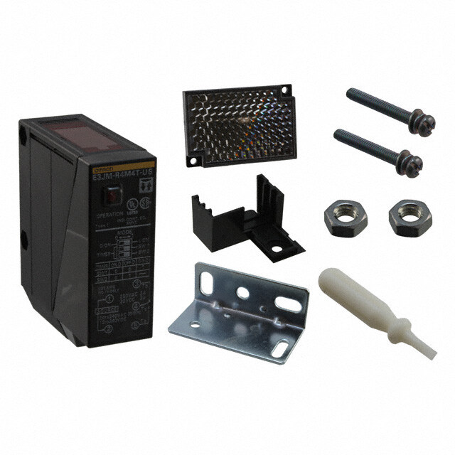
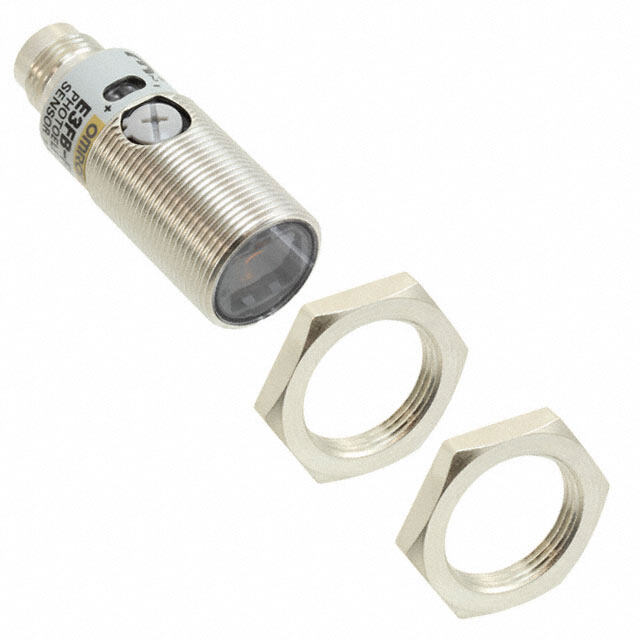
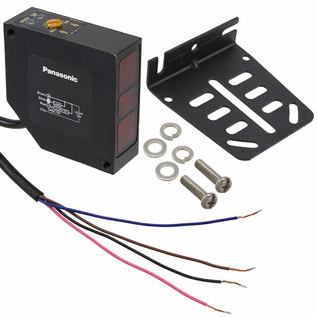
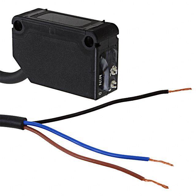
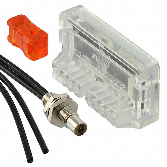
ICGOO电子元器件商城为您提供E3JM-R4M4TUS由Omron Electronics LLC设计生产,在icgoo商城现货销售,并且可以通过原厂、代理商等渠道进行代购。 E3JM-R4M4TUS价格参考。Omron Electronics LLCE3JM-R4M4TUS封装/规格:光传感器 - 光电,工业, Retroreflective Optical Sensor 157.480" (4m) Relay - Dark-ON/Light-ON - Selectable。您可以下载E3JM-R4M4TUS参考资料、Datasheet数据手册功能说明书,资料中有E3JM-R4M4TUS 详细功能的应用电路图电压和使用方法及教程。
欧姆龙(Omron Automation and Safety)E3JM-R4M4TUS是一款工业用光电传感器,属于光传感器类别。该型号采用反射式(漫反射型)检测原理,具备IP67防护等级,适用于较恶劣的工业环境。其主要应用场景包括:

1. 自动化生产线:用于检测物体的存在、位置或通过状态,如在装配线、包装线中检测产品是否到位,确保流程顺畅。

2. 物料搬运系统:在传送带、分拣设备中识别物品的有无,防止漏装或重复加工,提升物流效率。

3. 机械设备安全防护:配合机械臂或冲压设备,实时监控操作区域是否有异物进入,辅助实现安全联锁控制。

4. 食品与饮料行业:由于具备良好的防尘防水性能,可用于潮湿或多尘环境,如检测瓶罐、盒装产品的输送和填充过程。

5. 印刷与纸品加工:用于检测纸张、标签等薄型材料的位置与运行状态,避免卡纸或错位。

E3JM-R4M4TUS响应速度快、稳定性高,支持直流电源供电,安装简便,广泛适用于各类需要非接触检测的工业自动化场景,有效提升生产效率与系统可靠性。
| 参数 | 数值 |
| 产品目录 | |
| 描述 | REFLECTOR |
| 产品分类 | |
| 品牌 | Omron Automation and Safety |
| 数据手册 | |
| 产品图片 |
|
| 产品型号 | E3JM-R4M4TUS |
| rohs | 无铅 / 符合限制有害物质指令(RoHS)规范要求 |
| 产品系列 | E3JM |
| 侵入防护 | IEC IP66 |
| 光源 | 红外线 (660nm) |
| 其它名称 | E3JMR4M4TUS |
| 响应时间 | 30ms |
| 工作温度 | -25°C ~ 55°C |
| 感应方法 | 回射 |
| 感应距离 | 157.480"(4m) |
| 标准包装 | 1 |
| 电压-电源 | 12 V ~ 240 V, 24 V ~ 240 V |
| 电缆长度 | * |
| 调节类型 | - |
| 输出配置 | 继电器 - 暗光/亮光 - 可选 |
| 连接方法 | 端接块 |


- 商务部:美国ITC正式对集成电路等产品启动337调查
- 曝三星4nm工艺存在良率问题 高通将骁龙8 Gen1或转产台积电
- 太阳诱电将投资9.5亿元在常州建新厂生产MLCC 预计2023年完工
- 英特尔发布欧洲新工厂建设计划 深化IDM 2.0 战略
- 台积电先进制程称霸业界 有大客户加持明年业绩稳了
- 达到5530亿美元!SIA预计今年全球半导体销售额将创下新高
- 英特尔拟将自动驾驶子公司Mobileye上市 估值或超500亿美元
- 三星加码芯片和SET,合并消费电子和移动部门,撤换高东真等 CEO
- 三星电子宣布重大人事变动 还合并消费电子和移动部门
- 海关总署:前11个月进口集成电路产品价值2.52万亿元 增长14.8%

PDF Datasheet 数据手册内容提取
Built-in Power Supply Photoelectric Sensor E3JM CSM_E3JM_DS_E_12_3 Model Contribute to Overall Cost Reduction E3JM Terminal Block Models •Easy to wire and adjust. For the most recent information on models that have been certified for safety standards, refer to your OMRON website. Be sure to read Safety Precautions on page 6. Ordering Information Sensors (Refer to Dimensions on page 8.) Red light Infrared light Model Smeentshiondg Appearance Comnentehcotdion Sensing distance Opmeoradteion conOfiugtupruattion Functions Cothnrdeuaidt ssoizcek:et Cothnrdeuaidt ssoizcek:e t Cothnrdeuaidt ssoizcek:e t 1/2-14NPT PF1/2 PG13.5 UL-listed models Through- Relay --- E3JM-10M4-NN E3JM-10M4-G-NN E3JM-10M4-NN-US beam Timer E3JM-10M4T-NN E3JM-10M4T-G-NN E3JM-10M4T-NN-US (Emitter + --- E3JM-10S4-NN E3JM-10S4-G-NN E3JM-10S4-NN-US Receiver) * 10 m DC SSR Timer E3JM-10S4T-NN E3JM-10S4T-G-NN E3JM-10S4T-NN-US --- E3JM-R4M4 E3JM-R4M4-G E3JM-R4M4-US Retro- Light-ON Relay reflective Terminal Dark-ON Timer E3JM-R4M4T E3JM-R4M4T-G E3JM-R4M4T-US with MSR block 4 m (switch --- E3JM-R4S4 E3JM-R4S4-G E3JM-R4S4-US function E39-R1 (provided) selectable) DC SSR Timer E3JM-R4S4T E3JM-R4S4T-G E3JM-R4S4T-US --- E3JM-DS70M4 E3JM-DS70M4-G E3JM-DS70M4-US Relay Diffuse- Timer E3JM-DS70M4T E3JM-DS70M4T-G E3JM-DS70M4T-US 700 mm reflective --- E3JM-DS70S4 E3JM-DS70S4-G E3JM-DS70S4-US DC SSR Timer E3JM-DS70S4T E3JM-DS70S4T-G E3JM-DS70S4T-US *Through-beam Sensors are sold in sets that include both the Emitter and Receiver. An order for the Emitter or Receiver alone cannot be accepted. Note:Tightening nuts, washers, and rubber bushings are not provided with UL-listed models. Accessories (Order Separately) Slit (A Slit is not provided with the Sensor for through-beam. Order a Slit separately if required.) (Refer to Dimensions on page 8.) Minimum detectable Slit width Sensing distance object Model Quantity Remarks (reference value) (Seal-type long slit) 1 Slit each for the Can be used with the 1 mm × 20 mm E3JM-10@4(T)-NN 1.2 m 1-mm dia. E39-S39 Emitter and Re- E3JM-10@4(T)-NN, ceiver (2 Slits total) E3JM-10@4(T)-G-NN and E3JM-10@4(T)-NN-US Models. Reflectors (A Reflector is required for each Retro-reflective Sensor.) The E39-R1 Reflector is provided with the Sensor. Order other Reflectors separately if required. (Refer to Dimensions on E39-L/E39-S/E39-R.) Name Sensing distance Model Quantity Remarks Provided with the E3JM-R4@4(T), Reflectors E3JM-R4@4(T) 4 m E39-R1 1 E3JM-R4@4(T)-G and E3JM-R4@4(T)-US Models. Note:Refer to Reflectors on E39-L/E39-S/E39-R on your OMRON website for details. Mounting Bracket Some Mounting Brackets are provided with the Sensor. Order other Mounting Brackets separately if required. (Refer to E39-L/E39-S/E39-R) 1
E3JM Mounting Bracket Some Mounting Brackets are provided with the Sensor. Order other Mounting Brackets separately if required. (Refer to E39-L/E39-S/E39-R) Appearance Model Quantity Remarks E39-L53 1 Provided with the E3JM. E39-L51 1 Height of optical axis can be adjusted. Note:1.When using a Through-beam Sensor, order one Connector for the Receiver and one for the Emitter. 2. Refer to Mounting Brackets on E39-L/E39-S/E39-R on your OMRON website for details. 2
E3JM Ratings and Specifications Sensing method Retro-reflective model Through-beam model Diffuse-reflective model (with MSR function) E3JM-10@4(T)-NN E3JM-R4@4(T) E3JM-DS70@4(T) Item Model E3JM-10@4(T)-G-NN E3JM-R4@4(T)-G E3JM-DS70@4(T)-G E3JM-10@4(T)-NN-US E3JM-R4@4(T)-US E3JM-DS70@4(T)-US White paper (200 × 200 mm): Sensing distance 10 m 4 m (When using E39-R1) 700 mm Standard sensing object Opaque: 14.8-mm dia. min. Opaque: 75-mm dia. min. --- Differential travel --- 20% max. of sensing distance Directional angle 2B0o°th Emitter and Receiver 3° to 1° to 5° --- Light source (wavelength) Infrared LED (950 nm) Red LED (660 nm) Infrared LED (950 nm) 12 to 240 VDC±10%, ripple (p-p): 10% max. Power supply voltage 24 to 240 VAC±10%, 50/60 Hz 3 W max. (Emitter 1 W max. DC 2 W max. Power con- Receiver 2 W max.) sumption 3 W max. (Emitter 1 W max. AC 2 W max. Receiver 2 W max.) Relay output (E3JM-@@M4 (T)(-@) model): SPDT, 250 VAC, 3A (cosφ=1) max., 5 VDC, 10 mA min. Control output DC SSR output (E3JM-@@S4 (T)(-@) model): 48 VDC, 100 mA max. (residual voltage: 2 V max.) Light-ON/Dark-ON selectable Life Mechanical 50,000,000 times min. (switching frequency: 18,000 times/h) expectancy (relay output) Electrical 100,000 times min. (switching frequency: 1,800 times/h) Relay output (E3JM-@@M4 (T)(-@) models) Operate or reset: 30 ms max. Response time DC SSR output (E3JM-@@S4 (T)(-@) models) Operate or reset: 5 ms max. Sensitivity adjustment --- One-turn adjuster ON-delay/OFF-delay/One-shot delay switch selectable Timer function * Delay time: 0.1 to 5 s (adjustable), only for E3JM-@@@4T(-@) Ambient illumination Incandescent lamp: 3,000 lx max. (Receiver side) Ambient temperature range Operating: −25°C to 55°C, Storage: −30°C to 70°C (with no icing or condensation) Ambient humidity range Operating: 45% to 85% (with no condensation), Storage: 35% to 95% (with no condensation) Insulation resistance 20 MΩ min. at 500 VDC Dielectric strength 2,000 VAC, 50/60 Hz for 1 min. Vibration Destruction 10 to 55 Hz, 1.5-mm double amplitude for 2 hours each in X, Y, and Z directions resistance Malfunction 10 to 55 Hz, 1.5-mm double amplitude for 2 hours each in X, Y, and Z directions Shock Destruction 500 m/s2 3 times each in X, Y, and Z directions resistance Malfunction 100 m/s2 3 times each in X, Y, and Z directions Degree of protection IEC 60529: IP66 Connection method Terminal block Weight (packed state) Approx. 270 g Approx. 160 g Case ABS (Acrylonitril Butadiene Styrene) Lens Methacrylic resin Material Cover Polycarbonate Mounting Iron Bracket Mounting Bracket (with screw), Nuts, Terminal Protection Cover, One set of cable connection nuts (exclud- Accessories ing -US Models), Instruction manual, Reflector (E39-R1: only for Retro-reflective Sensors) *The timer cannot be disabled for models with timer functions (E3JM-@@@4T(-@)). 3
E3JM Engineering Data (Reference Value) Parallel Operating Range Through-beam Through-beam Retro-reflective E3JM-10@4(T)-NN E3JM-10@4(T)-NN + E39-S39 (Optional Slit) E3JM-R4@4(T) + E39-R1 (A Slit is mounted to the Emitter and (Supplied Reflector) Receiver.) m)600 m) 60 m)150 Reflector: E39-R1 m m m Distance Y (420000 Distance Y ( 4200 XY Distance Y (10500 0 0 0 2 4 6 8 10 12 14 16 0.5 1 1.5 2 2.5 3 3.5 1 2 3 4 5 6 7 8 Distance X (m) Distance X (m) −200 −20 Distance −50 X (m) −400 Y −40 −100 Y −600 X −60 −150 X Operating Range Diffuse-reflective E3JM-DS70@4(T) m) 60 Sensing object: 200 × 200 mm m 50 Y Y ( e 40 anc 30 X st Di 20 10 0 2 4 6 8 10 −10 Distance X (m) −20 −30 White paper Black carbon −40 SUS (Luster) Aluminum foil −50 (No luster on −60 the back) Sensing Object Size vs. Sensing Distance E3JM-DS70@4(T) m) 12 e ( nc a 10 Dist 8 White paper Black carbon SUS (Luster) 6 Aluminum foil (No luster on the back) 4 2 0 20 40 60 80 100 120 140 160 180 200220 Side length of sensing object (mm) 4
E3JM I/O Circuit Diagrams Relay Output Models Model Timing chart Output circuit 24 to 240 VAC Incident light 12 to 240 VDC E3JM-10M4(T)(-G)-NN(-US) NInod iicnactiodrent liOghNt PSciherconutsoioter lemcatrinic 12 No pSoPoolauwrrecitrey (red) * OFF E3JM-R4M4(T)(-G)(-US) ON 3 Tb L-ON (Ta) OFF 4 Tc Contact output E3JM-DS70M4(T)(-G)(-US) D-ON (Ta) ON 5 Ta OFF Refer to page 6 for information on Sensors with timers (T). (Built-in Relay: G6C) DC SSR Output Models Model Timing chart Output circuit 24 to 240 VAC 12 to 240 VDC 1 SPoouwrecre No polarity Incident light No incident light 2 E3JM-10S4(T)(-G)-NN(-US) Indicator ON E3JM-R4S4(T)(-G)(-US) (red) * OOFNF Drive L/ON3NO Load L-ON (Ta) OFF Circuit I1 E3JM-DS70S4(T)(-G)(-US) D-ON (Ta) OOFNF Photo- Drive D/ON5NC Load 4m8a xV.DC Refer to page 6 for information on Sensors with timers (T). eSleencstroicr Circuit I2 main circuit I1+I2<100 mA 4 COM Note:Connect terminal 1 to any polarity and terminal 2 to the power supply because there is no polarity on the Emitter side. * This is the light indicator on Sensors without a timer and the operation indicator on Sensors with a timer. 5
E3JM Safety Precautions Refer to Warranty and Limitations of Liability. WARNING This product is not designed or rated for ensuring safety of persons either directly or indirectly. Do not use it for such purposes. Precautions for Correct Use Do not use the product in atmospheres or environments that exceed product ratings. ● Designing Operation Note: The white part of the DIP switch indicates which setting is selected. Switch Switch selection Timing charts configuration M0 O D E1 M0 O D E1 Light-ON, Relay ON, Incident light Models D·ON L·ON D·ON L·ON DC output switching No incident light wtimitheorut M0 O D E1 Delaermk-eOnNt O, RNelay ON L·ONOOFNF Osepleecratotiron D·ON L·ON DelCem oeuntpt uOt Nswitching D·ONOOFNF ON-delay OFF-delay One-shot delay ON-delay OFF-delay One-shot delay M0 O D E1 M0 O D E1 M0 O D E1 M0 O D E1 D·ON L·ON D·ON L·ON D·ON L·ON D·ON L·ON Mwtimiothde rels TIMOSSEeepRlleeerccatttooiorr ns witcSShWW f12or TIMEBRoStWh 2S Wat1 "a0nSS."dWW 12 TIMOEnRly SW2 at SS "WW1."12 TIOwsMehnEtiltcRyinh Sg o Wovfe1 Sr arWidt e 2"s.SS1 ,WWe" it12her No IinnLDcc·ii·ddOOeeNnnNOOtt OOllFFiiggNNhhFFtt T T No IinnLDcc··iiOddOeeNNnnOOtt OOllFFiiggNNhhFFtt T T No IinnLDcc··iiOddOeeNNnnOOtt OOllFFiiggNNhhFFtt T T timer mode Note:The operation selector is the same as that for models without a timer. Output Relay Contact If E3JM is connected to a load with contacts that spark when the load is turned OFF (e.g., a contactor or valve), the normally-closed side may be turned ON before the normally-open side is turned OFF or vice-versa. If both normally-open output and normally-closed output are used simultaneously, apply an surge suppressor to the load. 6
E3JM ● Wiring ● Others Connecting and Wiring Terminal Protection Cover (Provided) •We recommend connecting a cable with a conductor cross-section The terminal protection cover is designed to improve safety by of 0.3 mm2 and an outer diameter of 6 to 8 mm. maintaining the sensitivity properties of the product and by preventing •Be sure to firmly tighten the cover in order to maintain waterproof any contact with charged sections while it is being operated with the and dustproof properties. The screw size of the conduit sockets is mode set to the timer mode. Mount the product as shown in the shown in the following table. following diagram (mount the Through-beam Model on the Receiver side). Model Conduit socket thread size E3JM-@ PF1/2 E3JM-@-G PG13.5 E3JM-@-US 1/2-14NPT •When using the DC SSR output model, the total of the load current for the Light-ON output (NO) and that for the Dark-ON (NC) should be 100 mA max. If the total exceeds 100 mA, the load short-circuit Terminal protection cover protection function will be activated (this function will be reset when E3JM the power of the Photoelectric Sensor is turned OFF). Cable End Treatment Adjust the four wires to the same length when the Ta output is to be used only. If both the Ta and Tb outputs are to be used, treat them as shown in the following diagram. Recommended example Ambient Conditions (Installation Area) Approx. The E3JM will malfunction if installed in the following places. 45 mm •Places where the E3JM is exposed to a dusty environment. Power •Places where corrosive gases are produced. source Tc, Ta Tb Rubber bushing (provided)* Approx. Washer (provided)* 55 mm Tightening nut (provided)* * These parts are not provided with models with a -US suffix. Recommended Crimp Terminal Dimensions (Unit: mm) Round type Fork type •Places where the E3JM is directly exposed to water, oil, or 10 max. 10 max. chemicals. 7 max. 7 max. 7 max. 7 max. 3.6 dia. min. 19 max. 3.6 dia. min. 19 max. (After crimping) (After crimping) Note:Use terminals with insulation tube (recommended crimp terminal: 1.25 to 3.5). 7
E3JM Dimensions (Unit: mm) Tolerance class IT16 applies to dimensions in this datasheet unless otherwise specified. Sensors E3JM-10@4(T)-NN E3JM-R4@4(T) E3JM-10@4(T)-G-NN E3JM-R4@4(T)-G E3JM-10@4(T)-NN-US E3JM-R4@4(T)-US E3JM-DS70@4(T) E3JM-DS70@4(T)-G E3JM-DS70@4(T)-US With Mounting Bracket Attached With Mounting Bracket Attached 8 8 6 24.5 6 24.5 22 6.4 6 (12.4) 22 6.4 6 (12.4) Mounting Holes 6 dia. 12.4 18 6 6 dia. 12.4 18 6 39.5 39.5 75 75 25 11.5 65 25 65 4.1 Indicator *1 11.5 4.1 Indicator *1 3 Lens: 14.8 dia. 3 Emitter 65 80 65 Optical axisTwo, M4´30 80 ReceiverTwo, M4´ 30 47.5 9 JIS *3 15 44(A) *2 1.6 9 20 JBPI FS01 2*/0322 15 (A) *2 1.6 20 40 HexagoBPn F0a12l/ 02n2ut 5 (Diagonal: 22) Mounting Holes Steel5 5440.5 H(ADpeipaxalgicgoaonbnalale: l 2cn2au)bt le: MountTiwnog, MH6oles Steel 54.5 A6 ptop l8ic adbiale. cable: Two, M6 *1. Emitter: Power indicator 6 to 8 dia. *1. Light indicator (without timer function) Receiver: Light indicator (without timer function) Operation indicator (with timer function) Operation indicator (with timer function) 42 *2. Mounting Brackets can be used on the A side. 42 **23.. MCoonudnutiint gs oBcrkaectk tehtrse caadn s bizee used on the A side. * 3 . C-Gon Mdoudit eslos:c kPeGt 1th3r.e5ad size -G Models: PG13.5 -US Models: 1/2-14NPT -US Models: 1/2-14NPT Note:The operating mode switch, timer mode switch, and Note:The operating mode switch and timer sensitivity adjuster (sensitivity adjuster: E3JM- mode switch are located inside the cover. DS70@4(T) only) are located inside the cover. Note:Models numbers for Through-beam Sensors (E3JM-10@4(T)(-G)-NN(-US)) are for sets that include both the Emitter and Receiver. Accessories (Order separately) Seal-type Long Slit Mounting Brackets E39-S39 Refer to E39-L/E39-S/E39-R on your OMRON website for details. 14 1±0.1 20 26.5 Materials: Polyester 0.1-mm thick 8
Terms and Conditions Agreement Read and understand this catalog. Please read and understand this catalog before purchasing the products. Please consult your OMRON representative if you have any questions or comments. Warranties. (a) Exclusive Warranty. Omron’s exclusive warranty is that the Products will be free from defects in materials and workmanship for a period of twelve months from the date of sale by Omron (or such other period expressed in writing by Omron). Omron disclaims all other warranties, express or implied. (b) Limitations. OMRON MAKES NO WARRANTY OR REPRESENTATION, EXPRESS OR IMPLIED, ABOUT NON-INFRINGEMENT, MERCHANTABILITY OR FITNESS FOR A PARTICULAR PURPOSE OF THE PRODUCTS. BUYER ACKNOWLEDGES THAT IT ALONE HAS DETERMINED THAT THE PRODUCTS WILL SUITABLY MEET THE REQUIREMENTS OF THEIR INTENDED USE. Omron further disclaims all warranties and responsibility of any type for claims or expenses based on infringement by the Products or otherwise of any intellectual property right. (c) Buyer Remedy. Omron’s sole obligation hereunder shall be, at Omron’s election, to (i) replace (in the form originally shipped with Buyer responsible for labor charges for removal or replacement thereof) the non-complying Product, (ii) repair the non-complying Product, or (iii) repay or credit Buyer an amount equal to the purchase price of the non-complying Product; provided that in no event shall Omron be responsible for warranty, repair, indemnity or any other claims or expenses regarding the Products unless Omron’s analysis confirms that the Products were properly handled, stored, installed and maintained and not subject to contamination, abuse, misuse or inappropriate modification. Return of any Products by Buyer must be approved in writing by Omron before shipment. Omron Companies shall not be liable for the suitability or unsuitability or the results from the use of Products in combination with any electrical or electronic components, circuits, system assemblies or any other materials or substances or environments. Any advice, recommendations or information given orally or in writing, are not to be construed as an amendment or addition to the above warranty. See http://www.omron.com/global/ or contact your Omron representative for published information. Limitation on Liability; Etc. OMRON COMPANIES SHALL NOT BE LIABLE FOR SPECIAL, INDIRECT, INCIDENTAL, OR CONSEQUENTIAL DAMAGES, LOSS OF PROFITS OR PRODUCTION OR COMMERCIAL LOSS IN ANY WAY CONNECTED WITH THE PRODUCTS, WHETHER SUCH CLAIM IS BASED IN CONTRACT, WARRANTY, NEGLIGENCE OR STRICT LIABILITY. Further, in no event shall liability of Omron Companies exceed the individual price of the Product on which liability is asserted. Suitability of Use. Omron Companies shall not be responsible for conformity with any standards, codes or regulations which apply to the combination of the Product in the Buyer’s application or use of the Product. At Buyer’s request, Omron will provide applicable third party certification documents identifying ratings and limitations of use which apply to the Product. This information by itself is not sufficient for a complete determination of the suitability of the Product in combination with the end product, machine, system, or other application or use. Buyer shall be solely responsible for determining appropriateness of the particular Product with respect to Buyer’s application, product or system. Buyer shall take application responsibility in all cases. NEVER USE THE PRODUCT FOR AN APPLICATION INVOLVING SERIOUS RISK TO LIFE OR PROPERTY OR IN LARGE QUANTITIES WITHOUT ENSURING THAT THE SYSTEM AS A WHOLE HAS BEEN DESIGNED TO ADDRESS THE RISKS, AND THAT THE OMRON PRODUCT(S) IS PROPERLY RATED AND INSTALLED FOR THE INTENDED USE WITHIN THE OVERALL EQUIPMENT OR SYSTEM. Programmable Products. Omron Companies shall not be responsible for the user’s programming of a programmable Product, or any consequence thereof. Performance Data. Data presented in Omron Company websites, catalogs and other materials is provided as a guide for the user in determining suitability and does not constitute a warranty. It may represent the result of Omron’s test conditions, and the user must correlate it to actual application requirements. Actual performance is subject to the Omron’s Warranty and Limitations of Liability. Change in Specifications. Product specifications and accessories may be changed at any time based on improvements and other reasons. It is our practice to change part numbers when published ratings or features are changed, or when significant construction changes are made. However, some specifications of the Product may be changed without any notice. When in doubt, special part numbers may be assigned to fix or establish key specifications for your application. Please consult with your Omron’s representative at any time to confirm actual specifications of purchased Product. Errors and Omissions. Information presented by Omron Companies has been checked and is believed to be accurate; however, no responsibility is assumed for clerical, typographical or proofreading errors or omissions. 2018.3 In the interest of product improvement, specifications are subject to change without notice. OMRON Corporation Industrial Automation Company http://www.ia.omron.com/ (c)Copyright OMRON Corporation 2018 All Right Reserved.