ICGOO在线商城 > 开发板,套件,编程器 > 配件 > DVA16XP280
 Datasheet下载
- 型号: DVA16XP280
- 制造商: Microchip
- 库位|库存: xxxx|xxxx
- 要求:
| 数量阶梯 | 香港交货 | 国内含税 |
| +xxxx | $xxxx | ¥xxxx |
查看当月历史价格
查看今年历史价格
DVA16XP280产品简介:
ICGOO电子元器件商城为您提供DVA16XP280由Microchip设计生产,在icgoo商城现货销售,并且可以通过原厂、代理商等渠道进行代购。 DVA16XP280价格参考。MicrochipDVA16XP280封装/规格:配件, ICE2000 - Adapter Board。您可以下载DVA16XP280参考资料、Datasheet数据手册功能说明书,资料中有DVA16XP280 详细功能的应用电路图电压和使用方法及教程。
Microchip Technology 的 DVA16XP280 是一款面向嵌入式系统开发的硬件开发工具,属于其开发套件类配件。该设备主要用于支持基于Microchip(原Atmel)AVR或SAM系列微控制器的应用开发与调试。

DVA16XP280 主要适用于以下应用场景:

1. 嵌入式系统开发:为开发人员提供一个平台,用于设计和测试基于Microchip 8位或32位微控制器的应用程序,如工业控制、家电控制、智能传感器等。

2. 原型设计与验证:工程师可以利用该开发平台快速搭建原型系统,验证硬件设计和软件功能,提高产品开发效率。

3. 教学与培训:适用于高校或培训机构进行嵌入式系统教学,帮助学生掌握微控制器编程、外设驱动、实时系统等关键技术。

4. 调试与仿真:支持在线调试(In-Circuit Debugging)和程序烧录功能,便于开发人员实时监控和优化代码运行情况。

5. 物联网(IoT)开发:结合Microchip的Wi-Fi、蓝牙或以太网解决方案,DVA16XP280也可用于物联网设备的通信模块开发与集成测试。

总之,DVA16XP280是一款面向中低端嵌入式应用的开发辅助设备,适合需要快速验证和开发基于Microchip微控制器系统的工程师和开发者使用。
| 参数 | 数值 |
| 产品目录 | 编程器,开发系统 |
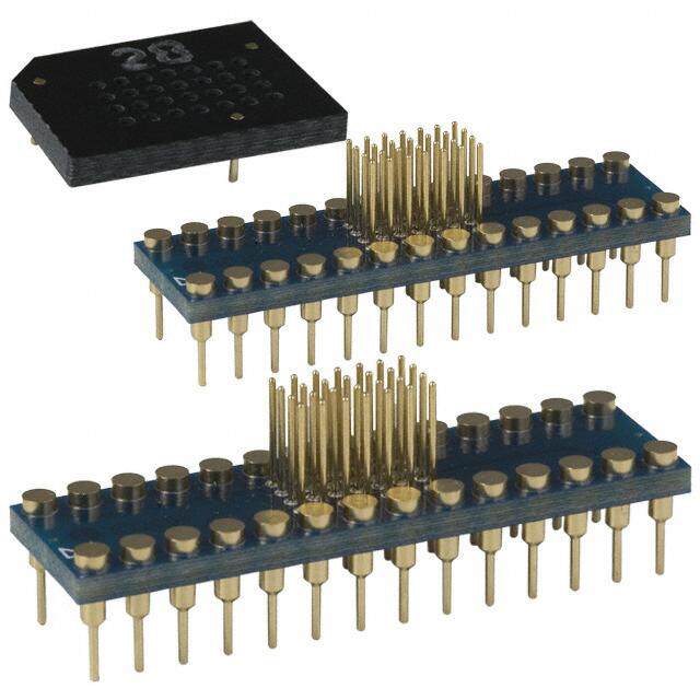
| 描述 | ADAPTER DEVICE FOR MPLAB-ICE |
| 产品分类 | |
| 品牌 | Microchip Technology |
| 数据手册 | |
| 产品图片 |
|
| 产品型号 | DVA16XP280 |
| rohs | 含铅 / 不符合限制有害物质指令(RoHS)规范要求 |
| 产品系列 | - |
| 产品目录页面 | |
| 标准包装 | 3 |
| 相关产品 | /product-detail/zh/PIC16C55A-40%2FSP/PIC16C55A-40%2FSP-ND/442557/product-detail/zh/PIC16C57C-40%2FSP/PIC16C57C-40%2FSP-ND/442538/product-detail/zh/PIC16C57C-20I%2FSP/PIC16C57C-20I%2FSP-ND/320070/product-detail/zh/PIC16C57C-20E%2FSP/PIC16C57C-20E%2FSP-ND/320066/product-detail/zh/PIC16C57C-04I%2FSP/PIC16C57C-04I%2FSP-ND/320061/product-detail/zh/PIC16C57C-04E%2FSP/PIC16C57C-04E%2FSP-ND/320059/product-detail/zh/PIC16C57-XTI%2FSP/PIC16C57-XTI%2FSP-ND/320054/product-detail/zh/PIC16C57-XTE%2FSP/PIC16C57-XTE%2FSP-ND/320052/product-detail/zh/PIC16C57-RCI%2FSP/PIC16C57-RCI%2FSP-ND/320047/product-detail/zh/PIC16C57-RCE%2FSP/PIC16C57-RCE%2FSP-ND/320044/product-detail/zh/PIC16C57-LPI%2FSP/PIC16C57-LPI%2FSP-ND/320040/product-detail/zh/PIC16C57-LPE%2FSP/PIC16C57-LPE%2FSP-ND/320037/product-detail/zh/PIC16C57-HSI%2FSP/PIC16C57-HSI%2FSP-ND/320032/product-detail/zh/PIC16C57-HSE%2FSP/PIC16C57-HSE%2FSP-ND/320030/product-detail/zh/PIC16C57-10%2FSP/PIC16C57-10%2FSP-ND/320026/product-detail/zh/PIC16C57-10I%2FSP/PIC16C57-10I%2FSP-ND/320022/product-detail/zh/PIC16C57-10E%2FSP/PIC16C57-10E%2FSP-ND/320018/product-detail/zh/PIC16C55A-20I%2FSP/PIC16C55A-20I%2FSP-ND/319887/product-detail/zh/PIC16C55A-04I%2FSP/PIC16C55A-04I%2FSP-ND/319878/product-detail/zh/PIC16C55-XTI%2FSP/PIC16C55-XTI%2FSP-ND/319816/product-detail/zh/PIC16C55-XTE%2FSP/PIC16C55-XTE%2FSP-ND/319814/product-detail/zh/PIC16C55-RCI%2FSP/PIC16C55-RCI%2FSP-ND/319809/product-detail/zh/PIC16C55-LPI%2FSP/PIC16C55-LPI%2FSP-ND/319802/product-detail/zh/PIC16C55-10%2FSP/PIC16C55-10%2FSP-ND/319788/product-detail/zh/PIC16C55-10I%2FSP/PIC16C55-10I%2FSP-ND/319784/product-detail/zh/XLT28XP/XLT28XP-ND/303501/product-detail/zh/PIC16C57C-20%2FSP/PIC16C57C-20%2FSP-ND/281903/product-detail/zh/PIC16C57C-04%2FSP/PIC16C57C-04%2FSP-ND/281898/product-detail/zh/PIC16C55A-20%2FSP/PIC16C55A-20%2FSP-ND/281892/product-detail/zh/PIC16C55A-04%2FSP/PIC16C55A-04%2FSP-ND/281887/product-detail/zh/PIC16C57-HS%2FSP/PIC16C57-HS%2FSP-ND/152209/product-detail/zh/PIC16C57-LP%2FSP/PIC16C57-LP%2FSP-ND/152204/product-detail/zh/PIC16C57-XT%2FSP/PIC16C57-XT%2FSP-ND/152199/product-detail/zh/PIC16C57-RC%2FSP/PIC16C57-RC%2FSP-ND/152192/product-detail/zh/PIC16C55-HS%2FSP/PIC16C55-HS%2FSP-ND/152187/product-detail/zh/PIC16C55-LP%2FSP/PIC16C55-LP%2FSP-ND/152182/product-detail/zh/PIC16C55-XT%2FSP/PIC16C55-XT%2FSP-ND/152177/product-detail/zh/PIC16C55-RC%2FSP/PIC16C55-RC%2FSP-ND/152175/product-detail/zh/PIC16C55-HSI%2FSP/PIC16C55-HSI%2FSP-ND/16106 |
| 配件类型 | 适配器板 |
| 配套使用产品/相关产品 | ICE2000 |


- 商务部:美国ITC正式对集成电路等产品启动337调查
- 曝三星4nm工艺存在良率问题 高通将骁龙8 Gen1或转产台积电
- 太阳诱电将投资9.5亿元在常州建新厂生产MLCC 预计2023年完工
- 英特尔发布欧洲新工厂建设计划 深化IDM 2.0 战略
- 台积电先进制程称霸业界 有大客户加持明年业绩稳了
- 达到5530亿美元!SIA预计今年全球半导体销售额将创下新高
- 英特尔拟将自动驾驶子公司Mobileye上市 估值或超500亿美元
- 三星加码芯片和SET,合并消费电子和移动部门,撤换高东真等 CEO
- 三星电子宣布重大人事变动 还合并消费电子和移动部门
- 海关总署:前11个月进口集成电路产品价值2.52万亿元 增长14.8%

PDF Datasheet 数据手册内容提取
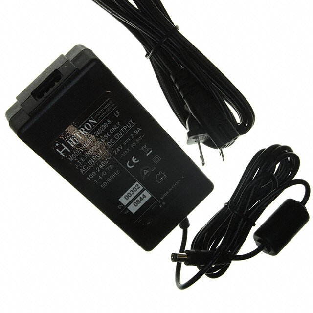
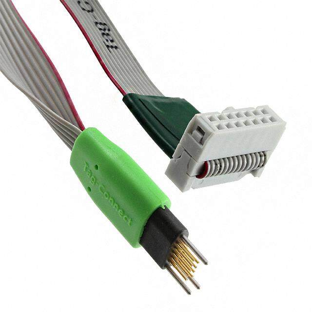
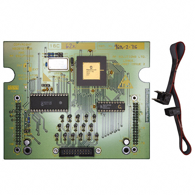
MPLABfi ICE 2000 Processor Module and Device Adapter Specification CONTENTS 2.0 MPLAB ICE 2000 SYSTEM 1.0 Introduction.........................................................1 A brief overview of the different components of the system is shown in the figure below. Each component 2.0 MPLAB ICE 2000 System...................................1 is discussed in the following subsections. 3.0 Emulator-Related Issues....................................2 FIGURE 2-1: MPLABfi ICE 2000 4.0 Processor Modules.............................................2 EMULATOR SYSTEM 5.0 Device Adapter Issues........................................4 Communications Cable 6.0 Device Adapter Target Footprints.....................10 Emulator Pod 1.0 INTRODUCTION Processor Module with Cable The processor modules for MPLAB ICE 2000 are Power Supply interchangeable personality modules that allow Cable MPLAB ICE 2000 to be reconfigured for emulation of Logic Probe Connector different PICmicrofi microcontrollers (MCUs). This modularity allows the emulation of many different devices with the addition of a processor module and Device Adapter device adapter, which provides a very cost effective Transition Socket multiprocessor emulation system. The device adapters for MPLAB ICE 2000 are inter- 2.1 Host to Pod Cable changeable assemblies that allow the emulator system to interface to a target application system. Device This is a standard parallel interface cable. MPLAB ICE adapters also have control logic that allows the target 2000 is tested with a 6-foot cable. A longer cable may application to provide a clock source and power to the work, but is not ensured. The cable connects to a par- processor module. The device adapters support allel port on the PC. If a PC has a printer connected to PICmicro MCUs in DIP, SDIP and PLCC packages. an LPT device, it is recommended that an additional interface card be installed, rather than using a splitter Transition sockets, used along with a device adapter, or an A/B switch. provide a method of accommodating all PICmicro MCU packages, including SOIC, SSOP, PQFP and TQFP 2.2 Emulator Pod packages. The Emulator Pod contains emulator memory and control logic. MPLAB ICE 2000 contains a main board and an additional board for expanded trace memory and complex control logic. There are no field service- able parts in the pod. For more information on the pod, see the MPLAB ICE 2000 on-line help file in MPLAB IDE (Help>Topics) or the (cid:147)MPLABfi ICE 2000 In-Circuit Emulator User(cid:146)s Guide(cid:148) (DS51488). The MPLAB ICE 2000 processor module is inserted into the pod for operation. 2.3 Processor Module The processor module contains the emulator chip, logic and low-voltage circuitry. There are no field-serviceable parts mounted on the printed circuit board housed within the processor module enclosure. © 2006 Microchip Technology Inc. DS51140M-page 1
MPLABfi ICE 2000 2.4 Flex Circuit Cable 3.0 EMULATOR-RELATED ISSUES Once the processor module is inserted into the General limitations that apply to the MPLAB ICE 2000 emulator pod, the flex circuit cable extends the emulator may be found in the on-line help. Select emulator system to the target application. This is a Help>Topics and then select (cid:147)MPLAB ICE 2000(cid:148) under custom cable that is attached inside the processor (cid:147)Debuggers(cid:148). module enclosure, and can be replaced in the field by Device-specific limitations can be found as above or by removing the end cap of the processor module selecting Debugger>Settings, clicking the Limitations enclosure. tab, and then clicking the Details button. Please, DO NOT PULL on the flex circuit cable to remove the processor module from the pod. Use the 4.0 PROCESSOR MODULES fins of the processor module end cap to leverage the Processor modules are identified on the top of the module from the pod. assembly (e.g., PCM18XA0). To determine which Emulator analog functions may not operate within the processors are supported by a specific module, refer to performance specifications published in the device the file (cid:147)Readme for MPLAB ICE 2000.txt(cid:148) in the data sheet due to parasitic capacitance (up to 120 pf) MPLAB IDE installation directory or the latest (cid:147)Product of the flex cable. Selector Guide(cid:148) (DS00148), which can be found on the Microchip web site at www.microchip.com. 2.5 Device Adapter A typical processor module contains a special bond-out The device adapter provides a common interface for version of a PICmicro MCU, with device buffers to the device being emulated. It is provided in standard control data flow and control logic. It provides the DIP and PLCC styles. The adapter alsocontains a spe- means of configuring the MPLAB ICE 2000 emulator cial device that provides an oscillator clock to accu- for a specific PICmicro MCU family and handles rately emulate the oscillator characteristics of the low-voltage emulation when needed. PICmicro MCU. Note: When removing the processor module, DO Due to components on the device adapter, which NOT PULL on the flex cable. Use the tabs require target power, the device adapter should be on the processor module or damage to the removed from the flex circuit cable (see Figure2-1) flex cable may occur. when emulator power is being used and the processor module is not connected to the target. This will 4.1 Power eliminate any loading effects on I/O pins. The operating voltage for most of the control logic and 2.6 Transition Socket buffering on the processor module is +5V and is supplied by the emulator pod. Power to the emulator Transition Sockets are available in various styles to processor and some of its surrounding buffers is user- allow a common device adapter to be connected to one selectable, and can be powered by the emulator pod of the supported surface mount package styles. Transi- (at +5V only) or the target application system (from tion sockets are available for various pin counts and 2.0V to 5.5V). This is software selectable and is pitches for SOIC, QFP and other styles. For more infor- mation on transition sockets, seethe (cid:147)MPLABfi ICE configurable through the MPLABfi IDE software. At no time will the emulator system directly power the target 2000/4000 Transition Socket Specification(cid:148) (DS51194). application system. ALWAYS insert the processor An emulator system consists of the following module into the emulator pod before applying power to components which can be ordered separately: the pod. (cid:149) An emulator pod (including the host-to-pod cable When connecting to a target application system, there and power supply) may be a voltage level on the target application even (cid:149) A processor module (including the flex circuit though power has not yet been applied to the target cable) application circuit. This is normal, and is due to current (cid:149) A device adapter leakage through VCC of the device adapter. The current leakage will typically be less than 20 mA. However, if (cid:149) An optional transition socket (for surface mount the target application is using a voltage regulator, it emulation) should be noted that some regulators require the use of an external shunt diode between VIN and VOUT for reverse-bias protection. Refer to the manufacturer(cid:146)s data sheets for additional information. DS51140M-page 2 © 2006 Microchip Technology Inc.
Processor Module and Device Adapter Specification 4.1.1 EMULATOR PROCESSOR POWER 4.1.4 OPERATING VOLTAGE OF 2.0 TO 4.6 SUPPLIED BY EMULATOR SYSTEM VOLTS If the emulator system is selected to power the emula- If the target application system(cid:146)s operating voltage is tor processor in the processor module, the emulator between 2.0V and 4.55V (–120 mV), the processor system can be operated without being connected to a module will consider this a LOW VOLTAGE condition. target application. If the system is being connected to a In this mode, the processor is limited to its rated speed target application, the power to the pod should be at a given voltage level (as indicated in its data sheet). applied before applying power to the target application. To minimize the amount of reverse current that the The target application system(cid:146)s VCC will experience a target system is exposed to, the recommended small current load (10 mA typical) when the emulator power-up sequence is: system is connected via a device adapter. This is 1. Apply power to the PC host. because the target system must always power the 2. Apply power to the emulator pod and processor clock chip in the processor module. module assembly. 4.1.2 EMULATOR PROCESSOR POWER 3. Invoke MPLAB IDE. SUPPLIED BY TARGET APPLICATION 4. Select Debugger > Settings and click the Power SYSTEM tab. Configure system for (cid:147)Processor Power Supplied by Target Board(cid:148). When the MPLAB IDE software is brought up, the 5. At the error message, apply power to the target emulator system is first initialized with the emulator application circuit. Then acknowledge the error. system powering the emulator processor. The (cid:147)Processor Power Supplied by Target Board(cid:148) option 6. Issue a System Reset (from the debugger may then be selected using the Power tab of the menu) before proceeding. Settings dialog (Debugger>Settings) to power the 7. Select Debugger > Settings and click the Power processor module from the target board. tab. Verify that the dialog says (cid:147)Low Voltage Enabled.(cid:148) Click Cancel to close the dialog. When operating from external power, the processor module will typically represent a current load equivalent 4.2 Operating Frequency to the device being emulated (according to its data sheet) plus approximately 100 mA. Keep in mind that The processor modules will support the maximum the target application will affect the overall current load frequency (except where noted in Section3.0 of the processor module, dependent upon the load (cid:147)Emulator-Related Issues(cid:148)) of the device under placed upon the processor I/O. emulation. The maximum frequency of a PICmicro When the processor power is supplied by the target MCU device is significantly lower when the operating application system, an external clock (from the target voltage is less than 4.5V. board) may also be provided. MPLAB IDE will not allow The processor modules will support a minimum use of an external clock without the use of external frequency of 32 kHz. When operating at low power. frequencies, response to the screen may be slow. 4.1.3 OPERATING VOLTAGE OF 4.6 TO 5.5 4.3 Clock Options VOLTS MPLAB ICE 2000 allows internal and external clocking. If the target application system(cid:146)s operating voltage is When set to internal, the clock is supplied from the between 4.55V (–120 mV) and 5.5V, the processor internal programmable clock, located in the emulator module will consider this a STANDARD VOLTAGE pod. When set to external, the oscillator on the target condition. In this mode, the processor can run to its application system will be utilized. highest rated speed (as indicated in its data sheet). 4.3.1 CLOCK SOURCE FROM EMULATOR The recommended power-up sequence is: 1. Apply power to the PC host. Refer to the MPLAB ICE 2000 on-line help file in 2. Apply power to the emulator pod and processor MPLAB IDE (Help>Topics) or the (cid:147)MPLABfi ICE 2000 module assembly. In-Circuit Emulator User(cid:146)s Guide(cid:148) (DS51488), (cid:147)Using the On-Board Clock(cid:148), for configuring MPLAB IDE to 3. Invoke MPLAB IDE. supply the clock source. 4. Select Debugger > Settings and click the Power tab. Configure system for (cid:147)Processor Power Supplied by Target Board(cid:148). 5. At the error message, apply power to the target application circuit. Then acknowledge the error. 6. Issue a System Reset (from the debugger menu) before proceeding. © 2006 Microchip Technology Inc. DS51140M-page 3
MPLABfi ICE 2000 4.3.2 CLOCK SOURCE FROM THE TARGET 4.5 Freeze Mode APPLICATION The MPLAB ICE 2000 system allows the option of If the target application is selected to provide the clock (cid:147)freezing(cid:148) peripheral operation or allowing them to source, the target board must also be selected to continue operating when the processor is halted. This power the emulator processor (see the MPLAB ICE option is configured in the MPLAB IDE. The Freeze 2000 on-line help file in MPLAB IDE (Help>Topics) or function is available on all processor modules except the (cid:147)MPLABfi ICE 2000 In-Circuit Emulator User(cid:146)s the PCM16XA0. Guide(cid:148) (DS51488), (cid:147)Using a Target Board Clock(cid:148)). This function is useful to halt an on-board timer while at At low voltage, the maximum speed of the processor a break point. At a break point and while single will be limited to the rated speed of the device under stepping, interrupts are disabled. emulation. An oscillator circuit on the device adapter generates a 5.0 DEVICE ADAPTER ISSUES clock to the processor module and buffers the clock This section details processor-specific considerations circuit on the target board. In this way, the MPLAB ICE that have been made on device adapters. Only 2000 emulator closely matches the oscillator options of adapters with special considerations are listed. the actual device. All oscillator modes are supported (as documented in the device(cid:146)s data sheet) except as There will be a max of 10 mA of current draw from the noted in Section3.0 (cid:147)Emulator-Related Issues(cid:148). The target system even when the emulator processor OSC1 and OSC2 inputs of the device adapter have a module is being powered by the emulator system, and 5pF to 10 pF load. Be aware of this when using a running internal clock. This is due to components on crystal in HS, XT, LP or LF modes, or an RC network in the device adapter being powered by the target board. RC mode. The frequency of the emulated RC network may vary relative to the actual device due to emulator circuitry. If a specific frequency is important, adjust the RC val- ues to achieve the desired frequency. Another alterna- tive would be to allow the emulator to provide the clock as described in Section4.3.1 (cid:147)Clock Source from Emulator(cid:148). When using the target board clock, the system(cid:146)s operating voltage is between 2.5V and 5.5V. 4.4 ESD Protection and Electrical Overstress All CMOS chips are susceptible to electrostatic discharge (ESD). In the case of the processor modules, the pins of the CMOS emulator are directly connected to the target connector, making the chip vulnerable to ESD. ESD can also induce latch-up in CMOS chips, causing excessive current through the chip and possible damage. MPLAB ICE 2000 has been designed to minimize potential damage by implement- ing overcurrent protection and transient suppressors. However, care should be given to minimizing ESD conditions while using the system. During development, contention on an I/O pin is possible (e.g., when an emulator pin is driving a (cid:145)1(cid:146) and the target board is driving a (cid:145)0(cid:146)). Prolonged contention may cause latch-up and damage to the emulator chip. One possible precaution is to use current limiting resistors (~100 Ω) during the development phase on bidirectional I/O pins. Using limiting resistors can also help avoid damage to modules, device adapters and pods that occurs when a voltage source is accidentally connected to an I/O pin on the target board. DS51140M-page 4 © 2006 Microchip Technology Inc.
Processor Module and Device Adapter Specification 5.1 DVA12XP080 This device adapter is intended for use with PIC12C50X 8-pin DIP devices. It has four mechanical switches that allow target pins GP2 to GP5 to be routed to the emulator silicon on the PCM16XA0 processor module or the oscillator chip on the device adapter, as shown in Table5-1. In addition, a 24C00 EEPROM (U1) is connected to RA0and RA1 of the emulator silicon to support the EEPROM capabilities of the PIC12CE51X family devices. For information on how to use EEPROM memory, see the MPLAB IDE on-line device-specific limitations for the PCM16XA0 (PIC12CE518/519) devices by selecting Debugger>Settings, clicking the Limitations tab, and then clicking the Details button. TABLE 5-1: DVA12XP080 DEVICE ADAPTER SWITCH ASSIGNMENT Desired Function Switch Positions RB2 Set S4 to RB2 RB3 Set S3 to RB3 RB4 Set S2 to RB4 RB5 Set S1 to RB5 MCLR Set S3 to MCLR External Oscillator Input Set S1 to OSC1 and set S2 to OSC2 TIMER0 Clock Input Set S4 to T0CKI 5.2 DVA12XP081 This device adapter is intended for use with PIC12C67X 8-pin DIP devices. It has two mechanical switches that allow target pins GP4 and GP5 to be routed to the emulator silicon on the PCM12XA0 processor module or the oscillator device on the device adapter, as shown in Table5-2. TABLE 5-2: DVA12XP081 DEVICE ADAPTER SWITCH ASSIGNMENT Desired Function Switch Positions GP4 Set S2 to GP4 GP5 Set S1 to GP5 External Oscillator Input Set S1 to OSC1 and set S2 to OSC2 © 2006 Microchip Technology Inc. DS51140M-page 5
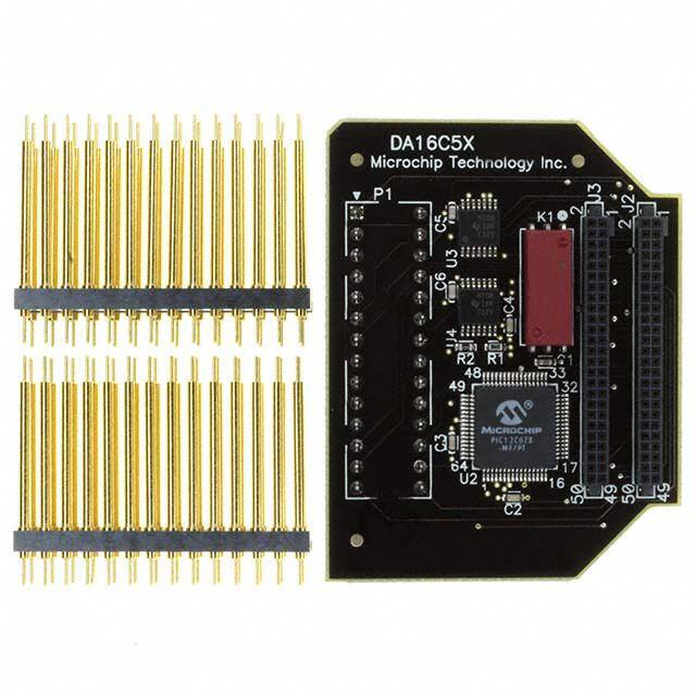
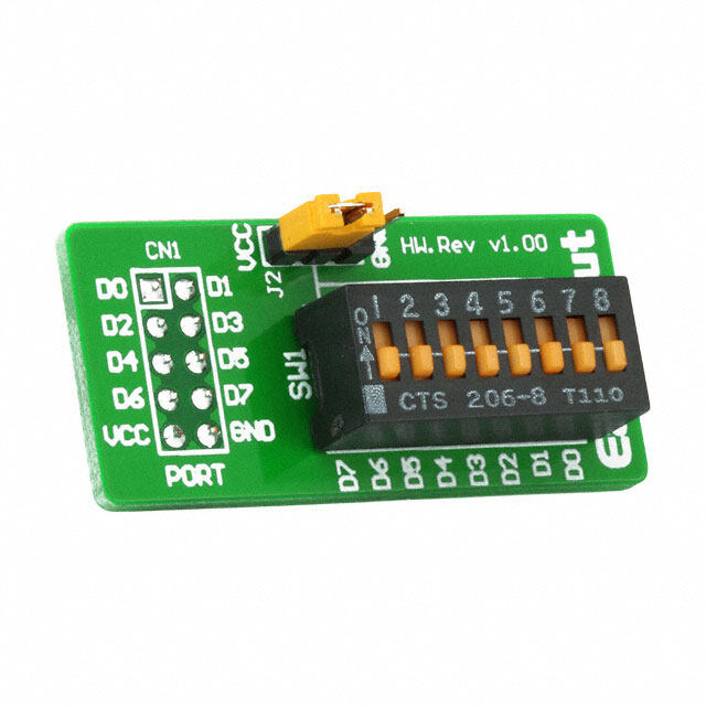
MPLABfi ICE 2000 5.3 DVA14XP280 This device adapter is intended for use with the PIC14000 28-pin DIP device. It has two mechanical switches that allow target pins OSC1 and OSC2 to be routed to the emulator silicon on the PCM14XA0 processor module or the oscillator device on the device adapter, as shown in Table5-3. TABLE 5-3: DVA14XP280 DEVICE ADAPTER SWITCH ASSIGNMENT Desired Function Switch Position IN Mode Set S1 to OSC2INT Set S2 to OSC1INT HS Mode Set S1 to OSC2EXT Set S2 to OSC1EXT 5.4 DVA16XP140 This device adapter is intended for use with the PIC16C505 14-pin DIP device. It has four mechanical switches. Two of the switches allow target pins RB4 and RB5 to be routed to the emulator silicon on the PCM16XA0 processor module or the oscillator device on the device adapter. The other two switches control the routing of RB3 and RC5 signals. RB3 can be a general purpose input or MCLR. RC5 can be a general purpose I/O or can drive the TOCKI input, as shown in Table5-4. TABLE 5-4: DVA16XP140 DEVICE ADAPTER SWITCH ASSIGNMENT Desired Function Switch Positions RC5 Set S4 to RC5 RB3 Set S3 to RB3 RB4 Set S2 to RB4 RB5 Set S1 to RB5 MCLR Set S3 to MCLR External Oscillator Input Set S1 to OSC1 and set S2 to OSC2 TIMER0 Clock Input Set S4 to T0CKI DS51140M-page 6 © 2006 Microchip Technology Inc.
Processor Module and Device Adapter Specification 5.5 DVA16XP182 This device adapter is intended for use with PIC16C712/716 18-pin DIP devices. It has a second oscillator device that allows TIMER1 oscillator input ranging from 32-40 kHz. It has four mechanical switches. Target pins RB1 and RB2 can be routed to the emulator silicon on the PCM16XE1 processor module or the TIMER1 oscillator device on the device adapter. Target pin RB1 is routed to T1CKI. Target pin RB3 can be a general purpose input or CCP1, as shown in Table5-5. TABLE 5-5: DVA16XP182 DEVICE ADAPTER SWITCH ASSIGNMENT Desired Function Switch Positions RB1 Set S2-1 to position B RB2 Set S2-2 to position B RB3 Set S2-3 to position B CCP1 Set S2-3 to position A TIMER1 Clock Input Set S2-1 to position A and set S1 to position B TIMER1 Oscillator Input Set S2-1 to position A and set S2-2 to position A and set S1 to position A © 2006 Microchip Technology Inc. DS51140M-page 7
MPLABfi ICE 2000 5.6 DVA16XP187 This device adapter is intended for use with PIC16F716 18-pin DIP devices. It has a second oscillator device that allows TIMER1 oscillator input ranging from 32-40 kHz. It has four mechanical switches. Target pins RB1 and RB2 can be routed to the emulator silicon on the PCM16YJ0 processor module or the TIMER1 oscillator device on the device adapter. Target pin RB1 is routed to T1CKI. Target pin RB3 can be a general purpose input or CCP1, as shown in Table5-5. TABLE 5-6: DVA16XP187 DEVICE ADAPTER SWITCH ASSIGNMENT Desired Function Switch Positions RB1 Set S2-1 to position B RB2 Set S2-2 to position B RB3 Set S2-3 to position B CCP1 Set S2-3 to position B TIMER1 Clock Input Set S2-1 to position B and set S1 to position B TIMER1 Oscillator Input Set S2-1 to position A and set S2-2 to position A and set S1 to position A 5.7 DVA16XP282, DVA16XP401, DVA16XL441 and DVA16PQ441 These device adapters are intended for use with PICmicro MCU devices supported by the PCM16XB0/B1, PCM16XE0/E1, PCM16XK0 and the PCM16XL0 processor modules. The device adapters have a second oscillator device that allows TIMER1 oscillator input ranging from 32 to 40 kHz. For PCM16XB0/B1, PCM16XE0/E1, PCM16XK0 and PCM16XL0, configure jumper J1 per Table5-7. For all other processor modules supported by these device adapters, leave the jumper on pins 1-2 (OFF); the Timer1 oscillator enable/disable function is software configurable. TABLE 5-7: DVA16XP282, DVA16XP401, DVA16XL441 AND DVA16PQ441 JUMPER SETTINGS Desired Function Switch Positions Results TIMER1 Oscillator Input enabled Short J1 pins 2-3 (ON) RC0/T1OSO/T1CKI pin = T1OSO RC1/T1OSI/CCP2 pin = T1OSI TIMER1 Oscillator Input disabled Short J1 pins 1-2 (OFF) RC0/T1OSO/T1CKI pin = RC0 or T1CKI RC1/T1OSI/CCP2 pin = RC1 or CCP2 DS51140M-page 8 © 2006 Microchip Technology Inc.
Processor Module and Device Adapter Specification 5.8 DVA17XXXX0 These device adapters are intended for use with PICmicro MCU devices supported by the PCM17XA0 processor module. In all processors in EC mode, OSC/4 is not supported. OSC/4 in EC mode is supported in DVA17XXXX1 device adapters. 5.9 Emulating a.600 28-Pin Part When emulating a.600 wide, 28-pin device, an adapter will be needed to convert the standard.300 wide socket on the device adapters to the.600 wide socket on the target board. There are many adapters available for this purpose, such as Digi-Key part number A502-ND. 5.10 T1OSC Jumper Some device adapters are equipped with a 3-pin jumper to force the device adapter to enable/disable the Timer1 oscillator circuitry. When in the (cid:147)ON(cid:148) position, the device adapter(cid:146)s Timer1 oscillator circuitry is always enabled regardless of the T1OSCEN bit in T1CON. When in the (cid:147)OFF(cid:148) position, the device adapter(cid:146)s Timer1 oscillator circuit is enabled/disabled by software in application code by the T1OSCEN bit in T1CON. Note: PCM16XB0/B1, PCM16XE0/E1, PCM16XK0 and PCM16XL0 do not support software enable/disable of the Timer1 circuitry and must use the jumper to either enable or disable the function (see Table5-7 for DVA16XP282, DVA16XP401, DVA16XL441 and DVA16PQ441). © 2006 Microchip Technology Inc. DS51140M-page 9
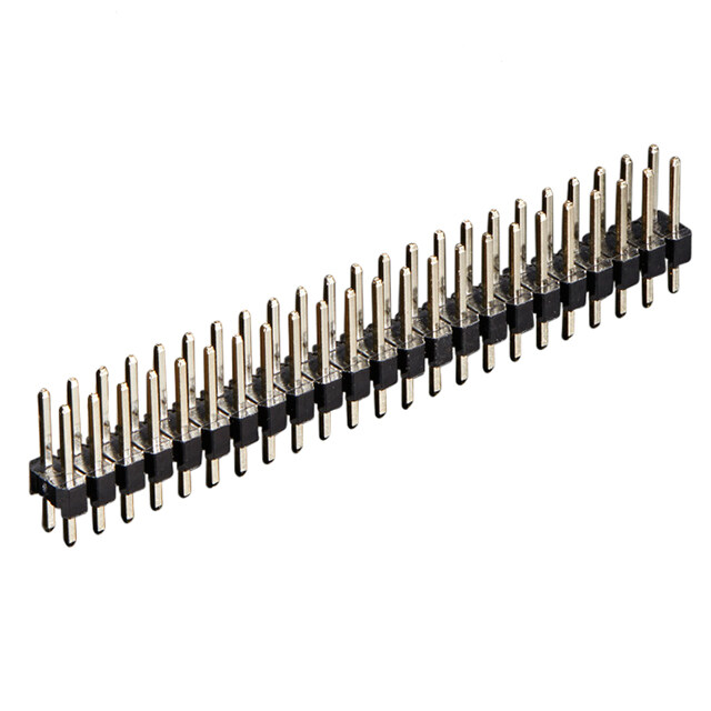
MPLABfi ICE 2000 6.0 DEVICE ADAPTER TARGET TABLE 6-1: DVA DIMENSIONS (cid:150) DIP FOOTPRINTS Package DVA Number* A B To connect an emulator device adapter directly to a 8P/14P DIP DVA1002 1.700 2.100 target board (without the use of transition sockets) the 8P/14P/20P DIP DVA1004 1.700 2.425 following information will be helpful. 8P DIP DVA12XP080 2.200 1.650 6.1 DIP Device Footprints 8P DIP DVA12XP081 2.200 1.650 DIP device adapter footprints shown will accept 14P DIP DVA16XP140 2.200 1.650 adapter plugs like Samtec series APA plugs. These 14P DIP DVA16XP141 2.000 2.100 plugs can be soldered in place during develop- 18P DIP DVA16XP180 2.200 1.650 ment/emulation and eliminate the need for any other 18P DIP DVA16XP182 2.000 2.100 sockets. 18P DIP DVA16XP183 2.150 2.575 FIGURE 6-1: DVA DRAWING (cid:150) DIP 18P DIP DVA16XP185 2.150 2.000 18P DIP DVA16XP186 2.000 2.100 B 18P DIP DVA16XP187 2.000 2.100 18P DIP DVA18XP180 2.150 2.575 x 20P DIP DVA16XP200 2.150 2.575 20P DIP DVA16XP201 2.150 1.825 A 20P DIP DVA16XP202 2.200 2.675 28P DIP DVA14XP280 2.200 1.700 28P DIP DVA16XP280 2.200 1.700 28P DIP DVA16XP282 2.000 2.100 x = Pin 1 location 28P DIP DVA18XP280 2.000 2.100 40P DIP DVA16XP401 2.200 2.200 See Table6-1 for A & B dimensions. 40P DIP DVA17XP401 2.200 2.000 40P DIP DVA18XP400 2.200 2.200 0.028 DIA PLATED-THRU 64P DIP DVA16XP640 2.500 2.050 0.100 HOLES * See the MPLABfi ICE 2000 Readme file for information on devices supported by each DVA. C DIP C DIP C 8-Pin 0.300 28-Pin 0.300 14-Pin 0.300 40-Pin 0.600 18-Pin 0.300 64-Pin 0.750 20-Pin 0.300 UNLESS OTHERWISE SPECIFIED, DIMENSIONS ARE IN INCHES. Drawing of DIP is 40-pin. DS51140M-page 10 © 2006 Microchip Technology Inc.
Processor Module and Device Adapter Specification 6.2 TQFP/PLCC Device Footprints FIGURE 6-3: DVA DRAWING (cid:150) DOUBLE-ROW TQFP/PLCC TQFP/PLCC device adapter footprints shown will accept board stackers like Samtec series DWM 0.050 B Pitch Stackers. These stackers can be soldered in place during development/emulation and eliminate the need for any other sockets. w(cid:146) x w FIGURE 6-2: DVA DRAWING (cid:150) SINGLE-ROW TQFP/PLCC A z(cid:146) x(cid:146) y B z y(cid:146) w(cid:146) x w, x, y, z = TQFP Pin 1 location w w(cid:146), x(cid:146), y(cid:146), z(cid:146) = PLCC Pin 1 location A z(cid:146) x(cid:146) See Table6-2 for A & B dimensions and y Pin 1 location. z y(cid:146) 0.028 DIA PLATED-THRU w, x, y, z = TQFP Pin 1 location HOLES w(cid:146), x(cid:146), y(cid:146), z(cid:146) = PLCC Pin 1 location See Table6-2 for A & B dimensions and Pin 1 location. 0.960 1.160 0.050 0.028 DIA PLATED-THRU 0.960 HOLES 1.160 C UNLESS OTHERWISE SPECIFIED, DIMENSIONS ARE IN INCHES. 0.050 C Device C 44-Pin (TQFP) 0.800 64/68-Pin (TQFP/PLCC) 0.960 80/84-Pin (TQFP/PLCC) 1.160 UNLESS OTHERWISE SPECIFIED, DIMENSIONS ARE IN INCHES. Drawing of device is 80/84-pin TQFP/PLCC. © 2006 Microchip Technology Inc. DS51140M-page 11
MPLABfi ICE 2000 Device adapter pin-out matches the PLCC package. (cid:149) DVA-68PL2 interface to 64-pin TQFP (cid:150) see PLCC will map to TQFP as follows: Figure6-5 for mapping. (cid:149) DVA-44PL interface to 44-pin TQFP (cid:150) one-to-one (cid:149) DVA-84PL interface to 80-pin TQFP (cid:150) see mapping. (No mapping diagram needed.) Figure6-6 for mapping. (cid:149) DVA-68PL interface to 64-pin TQFP (cid:150) see Figure6-4 for mapping. TABLE 6-2: DVA DIMENSIONS (cid:150) PLCC/TQFP Package DVA Number* Mapping Rows A B Pin 1 44P PLCC DVA16XL441 DVA (cid:150) 44PL Single 2.200 2.200 w(cid:146) 44P PLCC DVA17XL441 DVA (cid:150) 44PL Single 1.850 2.100 z(cid:146) 68P PLCC DVA16XL680 DVA (cid:150) 68PL2 Single 1.850 2.100 z(cid:146) 68P PLCC DVA17XL681 DVA (cid:150) 68PL Single 1.850 2.500 z(cid:146) 68P PLCC DVA18XL680 DVA (cid:150) 68PL Single 2.050 2.575 y(cid:146) 84P PLCC DVA17XL841 DVA (cid:150) 84PL Single 2.150 2.575 z(cid:146) 84P PLCC DVA18XL840 DVA (cid:150) 84PL Single 2.200 2.675 y(cid:146) 44P TQFP DVA16PQ441 DVA (cid:150) 44PL Single 2.200 2.300 y 44P TQFP DVA17PQ441 DVA (cid:150) 44PL Single 1.950 2.200 x 44P TQFP DVA18PQ440 DVA (cid:150) 44PL Single 2.200 2.300 y 64P TQFP DVA16PQ640 DVA (cid:150) 68PL2 Single 1.850 2.100 z 64P TQFP DVA17PQ641 DVA (cid:150) 68PL Single 1.850 2.500 z 64P TQFP DVA18PQ640 DVA (cid:150) 68PL Single 2.050 2.575 y 64P TQFP DVA1005 DVA (cid:150) 68PL Single 2.200 2.875 y 80P TQFP DVA17PQ801 DVA (cid:150) 84PL Single 2.150 2.575 z 80P TQFP DVA18PQ800 DVA (cid:150) 84PL Single 2.200 2.675 y 68/84P PLCC, 64/80P TQFP DVA18PQ802 DVA (cid:150) 68PL Double 2.200 2.675 y(cid:146), y DVA (cid:150) 84PL 68/84P PLCC, 64/80P TQFP DVA1003 DVA (cid:150) 68PL Double 2.200 2.975 y(cid:146), y DVA (cid:150) 84PL * See the MPLABfi ICE 2000 Readme file for information on devices supported by each DVA. DS51140M-page 12 © 2006 Microchip Technology Inc.
Processor Module and Device Adapter Specification FIGURE 6-4: DVA-68PL TO 64-PIN TQFP 64 49 NC = No Connection 68 60 52 1 1 NC 51 48 9 NC NC 43 16 17 NC 35 33 18 26 34 17 32 FIGURE 6-5: DVA-68PL2 TO 64-PIN TQFP 64 49 NC = No Connection 68 60 52 1 1 NC 51 48 NC 43 13 NC 16 17 NC 35 33 18 27 34 17 32 © 2006 Microchip Technology Inc. DS51140M-page 13
MPLABfi ICE 2000 FIGURE 6-6: DVA-84PL TO 80-PIN TQFP 80 61 NC = No Connection 84 74 64 1 1 NC 63 60 11 NC NC 53 20 21 NC 43 41 22 32 42 21 40 DS51140M-page 14 © 2006 Microchip Technology Inc.
Processor Module and Device Adapter Specification APPENDIX A: REVISION HISTORY Revision M (March 2006) (cid:149) Updated Table 5-2. © 2006 Microchip Technology Inc. DS51140M-page 15
MPLABfi ICE 2000 NOTES: DS51140M-page 16 © 2006 Microchip Technology Inc.
Note the following details of the code protection feature on Microchip devices: (cid:149) Microchip products meet the specification contained in their particular Microchip Data Sheet. (cid:149) Microchip believes that its family of products is one of the most secure families of its kind on the market today, when used in the intended manner and under normal conditions. (cid:149) There are dishonest and possibly illegal methods used to breach the code protection feature. All of these methods, to our knowledge, require using the Microchip products in a manner outside the operating specifications contained in Microchip(cid:146)s Data Sheets. Most likely, the person doing so is engaged in theft of intellectual property. (cid:149) Microchip is willing to work with the customer who is concerned about the integrity of their code. (cid:149) Neither Microchip nor any other semiconductor manufacturer can guarantee the security of their code. Code protection does not mean that we are guaranteeing the product as (cid:147)unbreakable.(cid:148) Code protection is constantly evolving. We at Microchip are committed to continuously improving the code protection features of our products. Attempts to break Microchip(cid:146)s code protection feature may be a violation of the Digital Millennium Copyright Act. If such acts allow unauthorized access to your software or other copyrighted work, you may have a right to sue for relief under that Act. Information contained in this publication regarding device Trademarks applications and the like is provided only for your convenience The Microchip name and logo, the Microchip logo, Accuron, and may be superseded by updates. It is your responsibility to dsPIC, KEELOQ, microID, MPLAB, PIC, PICmicro, PICSTART, ensure that your application meets with your specifications. PROMATE, PowerSmart, rfPIC, and SmartShunt are MICROCHIP MAKES NO REPRESENTATIONS OR WAR- registered trademarks of Microchip Technology Incorporated RANTIES OF ANY KIND WHETHER EXPRESS OR IMPLIED, in the U.S.A. and other countries. WRITTEN OR ORAL, STATUTORY OR OTHERWISE, RELATED TO THE INFORMATION, INCLUDING BUT NOT AmpLab, FilterLab, Migratable Memory, MXDEV, MXLAB, LIMITED TO ITS CONDITION, QUALITY, PERFORMANCE, SEEVAL, SmartSensor and The Embedded Control Solutions MERCHANTABILITY OR FITNESS FOR PURPOSE. Company are registered trademarks of Microchip Technology Microchip disclaims all liability arising from this information and Incorporated in the U.S.A. its use. Use of Microchip devices in life support and/or safety Analog-for-the-Digital Age, Application Maestro, dsPICDEM, applications is entirely at the buyer(cid:146)s risk, and the buyer agrees dsPICDEM.net, dsPICworks, ECAN, ECONOMONITOR, to defend, indemnify and hold harmless Microchip from any and FanSense, FlexROM, fuzzyLAB, In-Circuit Serial all damages, claims, suits, or expenses resulting from such Programming, ICSP, ICEPIC, Linear Active Thermistor, use. No licenses are conveyed, implicitly or otherwise, under MPASM, MPLIB, MPLINK, MPSIM, PICkit, PICDEM, any Microchip intellectual property rights. PICDEM.net, PICLAB, PICtail, PowerCal, PowerInfo, PowerMate, PowerTool, REAL ICE, rfLAB, rfPICDEM, Select Mode, Smart Serial, SmartTel, Total Endurance, UNI/O, WiperLock and Zena are trademarks of Microchip Technology Incorporated in the U.S.A. and other countries. SQTP is a service mark of Microchip Technology Incorporated in the U.S.A. All other trademarks mentioned herein are property of their respective companies. ' 2006, Microchip Technology Incorporated, Printed in the U.S.A., All Rights Reserved. Printed on recycled paper. Microchip received ISO/TS-16949:2002 quality system certification for its worldwide headquarters, design and wafer fabrication facilities in Chandler and Tempe, Arizona and Mountain View, California in October 2003. The Company(cid:146)s quality system processes and procedures are for its PICmicrofi 8-bit MCUs, KEELOQfi code hopping devices, Serial EEPROMs, microperipherals, nonvolatile memory and analog products. In addition, Microchip(cid:146)s quality system for the design and manufacture of development systems is ISO 9001:2000 certified. © 2006 Microchip Technology Inc. DS51140M-page 17
WORLDWIDE SALES AND SERVICE AMERICAS ASIA/PACIFIC ASIA/PACIFIC EUROPE Corporate Office Australia - Sydney India - Bangalore Austria - Wels 2355 West Chandler Blvd. Tel: 61-2-9868-6733 Tel: 91-80-4182-8400 Tel: 43-7242-2244-399 Chandler, AZ 85224-6199 Fax: 61-2-9868-6755 Fax: 91-80-4182-8422 Fax: 43-7242-2244-393 Tel: 480-792-7200 China - Beijing India - New Delhi Denmark - Copenhagen Fax: 480-792-7277 Tel: 86-10-8528-2100 Tel: 91-11-5160-8631 Tel: 45-4450-2828 Technical Support: Fax: 86-10-8528-2104 Fax: 91-11-5160-8632 Fax: 45-4485-2829 http://support.microchip.com Web Address: China - Chengdu India - Pune France - Paris Tel: 86-28-8676-6200 Tel: 33-1-69-53-63-20 www.microchip.com Tel: 91-20-2566-1512 Fax: 86-28-8676-6599 Fax: 91-20-2566-1513 Fax: 33-1-69-30-90-79 Atlanta China - Fuzhou Germany - Munich Alpharetta, GA Japan - Yokohama Tel: 770-640-0034 Tel: 86-591-8750-3506 Tel: 81-45-471- 6166 Tel: 49-89-627-144-0 Fax: 770-640-0307 Fax: 86-591-8750-3521 Fax: 81-45-471-6122 Fax: 49-89-627-144-44 Boston China - Hong Kong SAR Korea - Gumi Italy - Milan Westborough, MA Tel: 852-2401-1200 Tel: 82-54-473-4301 Tel: 39-0331-742611 Tel: 774-760-0087 Fax: 852-2401-3431 Fax: 82-54-473-4302 Fax: 39-0331-466781 Fax: 774-760-0088 China - Qingdao Korea - Seoul Netherlands - Drunen Chicago Tel: 86-532-8502-7355 Tel: 82-2-554-7200 Tel: 31-416-690399 Itasca, IL Fax: 86-532-8502-7205 Fax: 82-2-558-5932 or Fax: 31-416-690340 Tel: 630-285-0071 China - Shanghai 82-2-558-5934 Spain - Madrid Fax: 630-285-0075 Tel: 86-21-5407-5533 Malaysia - Penang Tel: 34-91-708-08-90 Dallas Fax: 86-21-5407-5066 Tel: 60-4-646-8870 Fax: 34-91-708-08-91 Addison, TX China - Shenyang Fax: 60-4-646-5086 UK - Wokingham Tel: 972-818-7423 Tel: 86-24-2334-2829 Philippines - Manila Tel: 44-118-921-5869 Fax: 972-818-2924 Fax: 86-24-2334-2393 Tel: 63-2-634-9065 Fax: 44-118-921-5820 Detroit China - Shenzhen Fax: 63-2-634-9069 Farmington Hills, MI Tel: 86-755-8203-2660 Singapore Tel: 248-538-2250 Fax: 86-755-8203-1760 Tel: 65-6334-8870 Fax: 248-538-2260 China - Shunde Fax: 65-6334-8850 Kokomo Tel: 86-757-2839-5507 Taiwan - Hsin Chu Kokomo, IN Fax: 86-757-2839-5571 Tel: 886-3-572-9526 Tel: 765-864-8360 China - Wuhan Fax: 886-3-572-6459 Fax: 765-864-8387 Tel: 86-27-5980-5300 Taiwan - Kaohsiung Los Angeles Fax: 86-27-5980-5118 Tel: 886-7-536-4818 Mission Viejo, CA China - Xian Fax: 886-7-536-4803 Tel: 949-462-9523 Tel: 86-29-8833-7250 Taiwan - Taipei Fax: 949-462-9608 Fax: 86-29-8833-7256 Tel: 886-2-2500-6610 San Jose Fax: 886-2-2508-0102 Mountain View, CA Thailand - Bangkok Tel: 650-215-1444 Tel: 66-2-694-1351 Fax: 650-961-0286 Fax: 66-2-694-1350 Toronto Mississauga, Ontario, Canada Tel: 905-673-0699 Fax: 905-673-6509 *DS51140M* 02/16/06 DS51140M-page 18 © 2006 Microchip Technology Inc.