ICGOO在线商城 > 继电器 > 信号继电器,高达 2 A > DS2E-S-DC12V
 Datasheet下载
- 型号: DS2E-S-DC12V
- 制造商: Panasonic Corporation
- 库位|库存: xxxx|xxxx
- 要求:
| 数量阶梯 | 香港交货 | 国内含税 |
| +xxxx | $xxxx | ¥xxxx |
查看当月历史价格
查看今年历史价格
DS2E-S-DC12V产品简介:
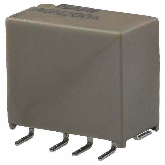
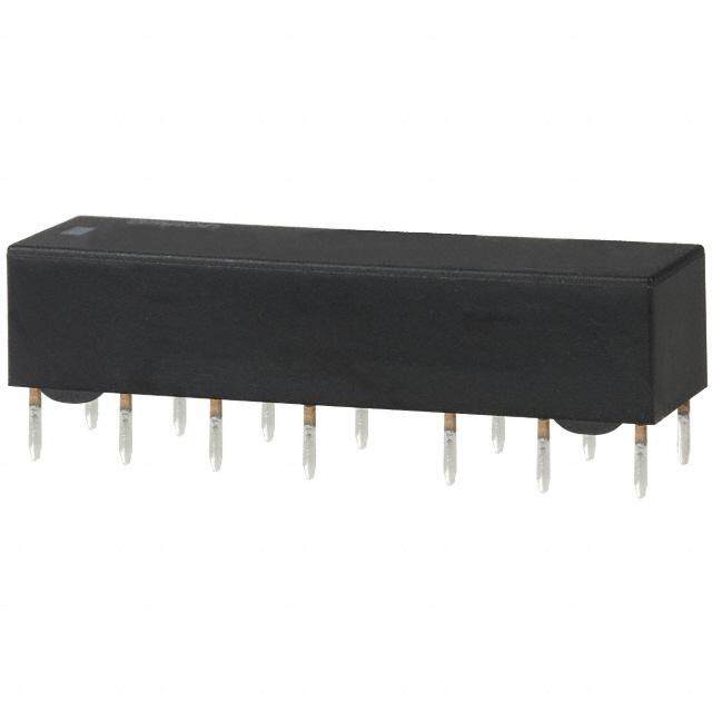
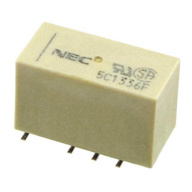
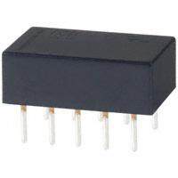
ICGOO电子元器件商城为您提供DS2E-S-DC12V由Panasonic Corporation设计生产,在icgoo商城现货销售,并且可以通过原厂、代理商等渠道进行代购。 DS2E-S-DC12V价格参考。Panasonic CorporationDS2E-S-DC12V封装/规格:信号继电器,高达 2 A, 通用 继电器 DPDT(2 Form C) 通孔。您可以下载DS2E-S-DC12V参考资料、Datasheet数据手册功能说明书,资料中有DS2E-S-DC12V 详细功能的应用电路图电压和使用方法及教程。
Panasonic Electric Works(现为 Panasonic Industrial Devices)生产的 DS2E-S-DC12V 信号继电器是一款小型、高性能的电磁继电器,其额定负载能力为 2 A,适用于多种低功率控制和信号切换场景。以下是该型号的一些典型应用场景:

 1. 工业自动化控制
   - 设备监控与保护:用于监测和控制工业设备中的温度、压力或液位传感器信号,实现自动化控制。
   - PLC 接口扩展:作为 PLC(可编程逻辑控制器)的外部扩展模块,用于切换低功率负载或传递信号。
   - 电机启动/停止控制:控制小型直流电机或辅助电路的通断。

 2. 汽车电子系统
   - 车载信号切换:在汽车电子系统中,用于切换灯光、雨刷器或其他低功耗设备的控制信号。
   - 电池管理系统 (BMS):用于监控和管理电池状态,确保安全运行。

 3. 家用电器
   - 智能家电控制:如空调、冰箱或洗衣机中的温控器、定时器等模块,用于信号传递或小功率负载切换。
   - 电源管理:用于家电内部的低功耗电路切换,例如待机模式下的电源控制。

 4. 通信与网络设备
   - 信号隔离与传输:在通信设备中用于隔离输入和输出信号,防止干扰。
   - 数据采集系统:用于切换传感器信号或将信号传递至中央处理单元。

 5. 医疗设备
   - 低功耗电路切换:用于医疗监护仪、呼吸机等设备中的信号传递或控制功能。
   - 报警系统:控制报警灯、蜂鸣器等低功率负载。

 6. 安防系统
   - 门禁控制:用于门锁、读卡器或其他安防设备的信号切换。
   - 监控摄像头控制:切换摄像头的电源或信号输出。

 特点总结:
- 小型化设计:适合空间有限的应用环境。
- 高可靠性:采用优质材料和精密制造工艺,确保长期稳定运行。
- 低功耗:线圈电压为 DC12V,适用于需要节能的场景。
- 耐久性好:支持频繁开关操作,使用寿命长。

DS2E-S-DC12V 的这些特性使其成为需要可靠信号切换和低功率负载控制的理想选择。
| 参数 | 数值 |
| 产品目录 | |
| 描述 | RELAY GEN PURPOSE DPDT 2A 12V低信号继电器 - PCB 2A 12VDC DPDT SEALED PCB |
| 产品分类 | |
| 品牌 | Panasonic Electric Works |
| 产品手册 | http://www3.panasonic.biz/ac/e_download/control/relay/signal/catalog/mech_eng_ds.pdf?f_cd=302232 |
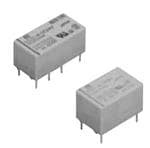
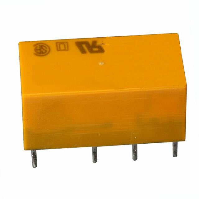
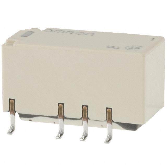
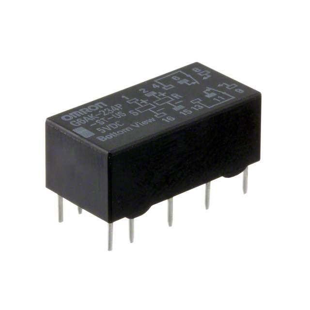
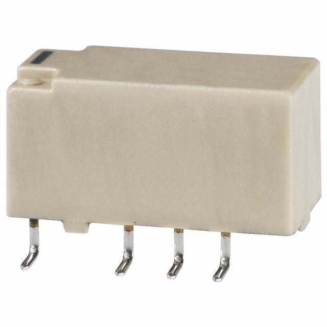
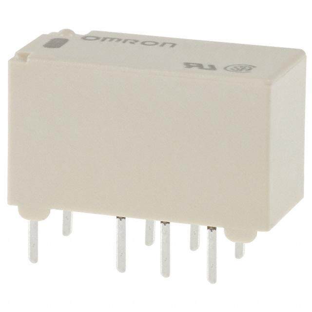
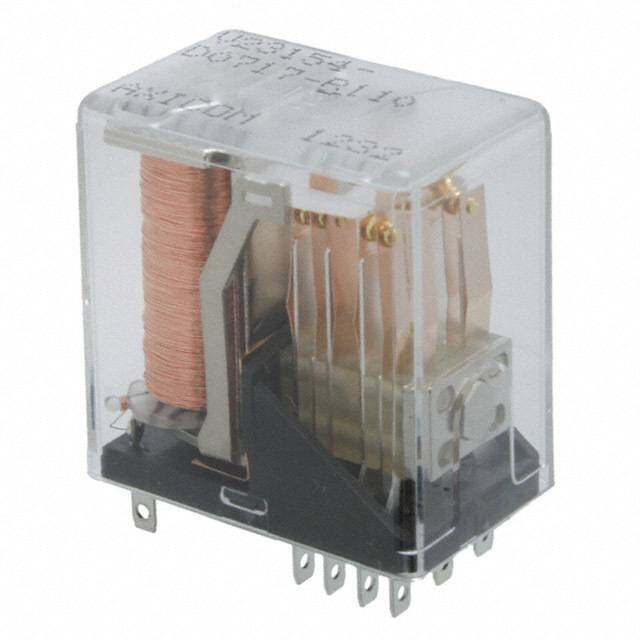
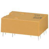
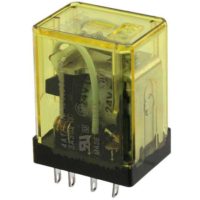
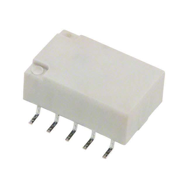
| 产品图片 |
|
| rohs | RoHS 合规性豁免无铅 / 符合限制有害物质指令(RoHS)规范要求 |
| 产品系列 | 低信号继电器 - PCB,Panasonic Industrial Devices DS2E-S-DC12VDS |
| 数据手册 | |
| 产品型号 | DS2E-S-DC12V |
| 产品 | Low Profile Relays |
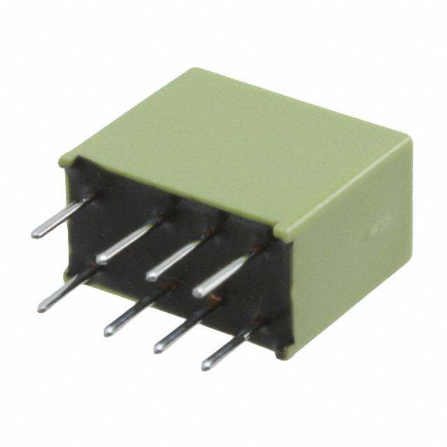
| 产品目录绘图 |
|
| 产品目录页面 | |
| 产品种类 | 低信号继电器 - PCB |
| 关闭电压(最小值) | 1.2 VDC |
| 其它名称 | 255-1063 |
| 其它有关文件 | |
| 功耗 | 200 mW |
| 包装 | 管件 |
| 商标 | Panasonic Industrial Devices |
| 安装类型 | 通孔 |
| 安装风格 | Through Hole |
| 导通电压(最大值) | 8.4 VDC |
| 封装 | Tube |
| 工作时间 | 10ms |
| 工作温度 | -40°C ~ 70°C |
| 工厂包装数量 | 50 |
| 开关电压 | 250VAC,220VDC - 最小值 |
| 最大开关电流 | 3 A |
| 标准包装 | 50 |
| 特性 | 密封 - 琥珀色 |
| 端子类型 | PC 引脚 |
| 端接类型 | Solder Pin |
| 类型 | Miniature |
| 线圈功率 | 200 mW |
| 线圈电压 | 12VDC |
| 线圈电流 | 16.7mA |
| 线圈电阻 | 720 欧姆 |
| 线圈类型 | 无锁存 |
| 继电器类型 | 通用 |
| 触头外形 | DPDT(2 C 型) |
| 触头材料 | Silver(Ag),Gold(Au) |
| 触点形式 | DPDT (2 Form C) |
| 触点电流额定值 | 3 A |
| 触点额定值 | 2 A at 30 VDC |
| 释放时间 | 5ms |
| 额定接触(电流) | 2A |


- 商务部:美国ITC正式对集成电路等产品启动337调查
- 曝三星4nm工艺存在良率问题 高通将骁龙8 Gen1或转产台积电
- 太阳诱电将投资9.5亿元在常州建新厂生产MLCC 预计2023年完工
- 英特尔发布欧洲新工厂建设计划 深化IDM 2.0 战略
- 台积电先进制程称霸业界 有大客户加持明年业绩稳了
- 达到5530亿美元!SIA预计今年全球半导体销售额将创下新高
- 英特尔拟将自动驾驶子公司Mobileye上市 估值或超500亿美元
- 三星加码芯片和SET,合并消费电子和移动部门,撤换高东真等 CEO
- 三星电子宣布重大人事变动 还合并消费电子和移动部门
- 海关总署:前11个月进口集成电路产品价值2.52万亿元 增长14.8%
PDF Datasheet 数据手册内容提取
1 Form C / 2 Form C, 2 A, DS RELAYS 200 mW Nominal operating power relays FEATURES TYPICAL APPLICATIONS 1.1 Form C / 2 Form C contact 1.Telecommunications and 2.Available 2 coil latching type measuring devices 3.DIL terminal array enables use of IC 2.Office equipment sockets 3.Computers and related equipment 4.Industrial equipment RoHS compliant ORDERING INFORMATION DS E Contact arrangement 1: 1 Form C 2: 2 Form C M:Standard type S: High sensitivity type Operating function Nil:Single side stable L2:2 coil latching Nominal coil voltage DC 1.5, 3, 5, 6, 9, 12, 24, 48 V Note: * Nominal coil voltage 1.5V type are 1 Form C only. –1– ASCTB17E 201504-T
DS TYPES High sensitivity type Standard type Contact Nominal coil Single side stable type 2 coil latching type Single side stable type 2 coil latching type arrangement voltage Part No. Part No. Part No. Part No. 1.5 V DC DS1E-S-DC1.5V DS1E-SL2-DC1.5V DS1E-M-DC1.5V DS1E-ML2-DC1.5V 3 V DC DS1E-S-DC3V DS1E-SL2-DC3V DS1E-M-DC3V DS1E-ML2-DC3V 5 V DC DS1E-S-DC5V DS1E-SL2-DC5V DS1E-M-DC5V DS1E-ML2-DC5V 6 V DC DS1E-S-DC6V DS1E-SL2-DC6V DS1E-M-DC6V DS1E-ML2-DC6V 1 Form C 9 V DC DS1E-S-DC9V DS1E-SL2-DC9V DS1E-M-DC9V DS1E-ML2-DC9V 12 V DC DS1E-S-DC12V DS1E-SL2-DC12V DS1E-M-DC12V DS1E-ML2-DC12V 24 V DC DS1E-S-DC24V DS1E-SL2-DC24V DS1E-M-DC24V DS1E-ML2-DC24V 48 V DC DS1E-S-DC48V DS1E-SL2-DC48V DS1E-M-DC48V DS1E-ML2-DC48V 3 V DC DS2E-S-DC3V DS2E-SL2-DC3V — — 5 V DC DS2E-S-DC5V DS2E-SL2-DC5V — — 6 V DC DS2E-S-DC6V DS2E-SL2-DC6V — — 2 Form C 9 V DC DS2E-S-DC9V DS2E-SL2-DC9V — — 12 V DC DS2E-S-DC12V DS2E-SL2-DC12V — — 24 V DC DS2E-S-DC24V DS2E-SL2-DC24V — — 48 V DC DS2E-S-DC48V DS2E-SL2-DC48V — — Standard packing: Carton: 50 pcs.; Case: 500 pcs. RATING 1. Coil data 1) Single side stable type Type Novmoilntaagl ecoil P(aict k2-0u°pC v o6l8ta°Fge) D(raotp 2-0o°uCt v6o8lt°aFg)e Nomin(aatl o2[±p01e°C0ra% t6in]8 g°F c)urrent Coil (raets 2is0t°aCn c6e8 °[±F1)0%] Nominpaol wopeerrating (aMt 5av0xo.° lCatap 1gp2eli2 e°dF ) 1.5 V DC 266.7 mA 5.63 Ω 3 V DC 133.3 mA 22.5 Ω 5 V DC 80.0 mA 62.5 Ω Standard 6 V DC 70%V or less of 10%V or more of 66.7 mA 90 Ω 1 Form C: nominal voltage nominal voltage 400 mW 120%V of (M) type 9 V DC (Initial) (Initial) 44.4 mA 203 Ω nominal voltage 12 V DC 33.3 mA 360 Ω 24 V DC 16.7 mA 1,440 Ω 48 V DC 8.3 mA 5,760 Ω 1.5 V DC 133.3 mA 11.3 Ω 3 V DC 1 Form C: 66.7 mA 45 Ω 1 Form C: 5 V DC 80%V or less of 40.0 mA 125 Ω 160%V of nominal voltage High 6 V DC 10%V or more of 33.3 mA 180 Ω nominal voltage sensitivity nominal voltage 200 mW (S) type 9 V DC 2 Form C: (Initial) 22.2 mA 405 Ω 2 Form C: 12 V DC 70%V or less of 16.7 mA 720 Ω 220%V of nominal voltage 24 V DC (Initial) 8.3 mA 2,880 Ω nominal voltage 48 V DC 4.2 mA 11,520 Ω 2) 2 coil latching type Type Novmoilntaagl ecoil (aSt e2t0 v°Col t6a8g°eF ) (Raet s2e0t° Cvo 6lt8a°gFe) Nomin(aatl o2[±p01e°C0ra% t6in]8 g°F c)urrent Coil (raets 2is0t°aCn c6e8 °[±F1)0%] Nominpaol wopeerrating (aMt 5av0xo.° lCatap 1gp2eli2 e°dF ) Set coil Reset coil Set coil Reset coil Set coil Reset coil 1.5 V DC 240 mA 240 mA 6.25 Ω 6.25 Ω 3 V DC 120 mA 120 mA 25 Ω 25 Ω 5 V DC 72 mA 72 mA 69.4 Ω 69.4 Ω Standard 6 V DC 70%V or less of 70%V or less of 60 mA 60 mA 100 Ω 100 Ω 1 Form C: nominal voltage nominal voltage 360 mW 360 mW 120%V of (M) type 9 V DC (Initial) (Initial) 40 mA 40 mA 225 Ω 225 Ω nominal voltage 12 V DC 30 mA 30 mA 400 Ω 400 Ω 24 V DC 15 mA 15 mA 1,600 Ω 1,600 Ω 48 V DC 7.5 mA 7.5 mA 6,400 Ω 6,400 Ω 1.5 V DC 120 mA 120 mA 12.5 Ω 12.5 Ω 3 V DC 1 Form C: 1 Form C: 60 mA 60 mA 50 Ω 50 Ω 1 Form C: 5 V DC 80%V or less of 80%V or less of 36 mA 36 mA 139 Ω 139 Ω 160%V of nominal voltage nominal voltage High 6 V DC 30 mA 30 mA 200 Ω 200 Ω nominal voltage sensitivity 180 mW 180 mW (S) type 9 V DC 2 Form C: 2 Form C: 20 mA 20 mA 450 Ω 450 Ω 2 Form C: 12 V DC 70%V or less of 70%V or less of 15 mA 15 mA 800 Ω 800 Ω 220%V of nominal voltage nominal voltage 24 V DC (Initial) (Initial) 7.5 mA 7.5 mA 3,200 Ω 3,200 Ω nominal voltage 48 V DC 3.75 mA 3.75 mA 12,800 Ω 12,800 Ω –2– ASCTB17E 201504-T
DS 2. Specifications Characteristics Item Specifications Arrangement 1 Form C 2 Form C Contact Initial contact resistance, max. Max. 50 mΩ (By voltage drop 6 V DC 1A) Contact material Ag+Au clad Nominal switching capacity 2 A 30 V DC (resistive load) Max. switching power 60 W, 125 VA (resistive load) Max. switching voltage 220 V DC, 250 V AC Rating Max. carrying current 3 A Min. switching capacity (Reference value)*1 10μA 10m V DC Single side stable (M type: 400 mW, S type: 200 mW); Nominal operating power latching (M type: 360 mW, S type: 180 mW) Min. 100MΩ (at 500V DC) Insulation resistance (Initial) Measurement at same location as “Initial breakdown voltage” section. 1,000 Vrms for 1min. Between open contacts Breakdown voltage (500 Vrms for 1min: 1 Form C type) (Detection current: 10mA.) (Initial) 1,500 Vrms for 1min. Electrical Between contact and coil (1,000 Vrms for 1min: 1 Form C type) (Detection current: 10mA.) characteristics Max. 65°C Temperature rise (By resistive method, nominal coil voltage applied to the coil, contact carrying current: 2A.) Operate time [Set time] (at 20°C 68°F) Max. 10 ms [10 ms] (Nominal coil voltage applied to the coil, excluding contact bounce time.) Release time [Reset time] (at 20°C 68°F) Max. 5 ms [10 ms] (Nominal coil voltage applied to the coil, excluding contact bounce time.) (without diode) Functional*2 Min. 490 m/s2 Min. 490 m/s2 Shock resistance Mechanical Destructive Min. 980 m/s2 (Half-wave pulse of sine wave: 6 ms.) characteristics Functional 10 to 55 Hz at double amplitude of 3.3 mm (Detection time: 10μs.) Vibration resistance Destructive 10 to 55 Hz at double amplitude of 5 mm Mechanical Min. 108 (107: 1 Form C latching type) (at 600 cpm) Expected life Electrical Min. 5×10⁵ rated load (at 60 cpm) Ambient temperature: –40°C to +70°C –40°F to +158°F Conditions for operation, transport and storage*3 Conditions Humidity: 5 to 85% R.H. (Not freezing and condensing at low temperature) Max. operating speed (at rated load) 60 cpm Unit weight Approx. 3 g .11 oz Approx. 4g .14oz Notes:*1 This value can change due to the switching frequency, environmental conditions, and desired reliability level, therefore it is recommended to check this with the actual load. TX/TX-S/TX-D relay AgPd contact type are available for low level load switching (10V DC, 10mA max. level). *2 Half-wave pulse of sine wave: 11ms; detection time: 10μs *3 Refer to “AMBIENT ENVIRONMENT” in GENERAL APPLICATION GUIDELINES. –3– ASCTB17E 201504-T
DS REFERENCE DATA 1. Maximum switching capacity 2. Life curve (Resistive load) 3. Contact reliability for AC loads Tested sample: DS2E-S-DC24V 10 pcs. Operating speed: 20 cpm. Detection level: 200 mΩ 1,000V 401,000 F(t), %999599...009 Contact voltage, DC11000VV ×No. of operations, 111000 1253 V0 AVC DC 13571250000.......0000000 1A5 A1 22550V V AACC 0.3A 250V AC0.5A 125V AC 0.5 0. Weibull 0.2 probability data 10mV 0.1 10μA 100mA 1A 0 1 2 0 10 100 1,000 Switching current Switching current, A No. of operations, ×104 4. Operate and release time characteristics 5-(1). Influence of adjacent mounting 5-(2). Influence of adjacent mounting (2 Form C single side stable type) (1 Form C) (2 Form C) Test condition: Without diode connected to coil in parallel 4 % % ms nge, 10 Pick-up voltage (O1FF)(2)(O3FF) nge, 10 Pick-up voltage (O1FF)(2)(O3FF) ease time, 3 Operate time (mean) Rate of cha–100 ON ON Rate of cha–100 ON ON el d r 2 Operate an 1 Release time (mean) of change, % 100 Drop-out voltage OOFNF OOFNF of change, % 100 Drop-out voltage OOFNF OOFNF e e at–10 at–10 R R 0 80 100 120 5 10 5 10 Coil applied voltage, % .197 .394 .197 .394 Inter-relay distance , mminch Inter-relay distance , mminch DIMENSIONS (mm inch) The CAD data of the products with a CAD Data mark can be downloaded from: http://industrial.panasonic.com/ac/e/ DS (1 Form C) Single side stable, 2 coil latching PC board pattern (Bottom view) CAD Data External dimensions Single side stable 2 coil latching 15 9.9 2.54 5-0.9 dia. 2.54 6-0.9 dia. .590 .390 .100 5-.035 dia. .100 6-.035 dia. 2.54 2.54 .100 .100 9.3 .93.990.366 .00.264 7.62 7.62 .300 .300 3.4 .134 5.08 7.62 0.0.624 .52.261 0.0.312 .52.0008 7.3.6020 5.2.0080 7.3.6020 .200 .300 7.62 .300 Schematic (Bottom view) General tolerance: ±0.3 ±.012 Single side stable 2 coil latching 1 6 1 3 6 12 10 7 12 10 7 (Deenergized condition) (Reset condition) Tolerance: ±0.1 ±.004 –4– ASCTB17E 201504-T
DS DS (2 Form C) Single side stable CAD Data External dimensions PC board pattern (Bottom view) 20 9.9 2.54 8-0.9 dia. .780 .390 .100 8-.035 dia. 2.54 .100 9.3 9.9.366 .00.264 .390 7.62 .300 3.4 .134 5.2.0080 5.2.0080 7.3.6020 0.0.624 7.52.6.2621 0.0.312 5.2.0080 5.2.0080 7.3.6020 .300 Schematic (Bottom view) General tolerance: ±0.3 ±.012 9 11 13 16 8 6 4 1 (Deenergized condition) Tolerance: ±0.1 ±.004 DS (2 Form C) 2 coil latching CAD Data External dimensions PC board pattern (Bottom view) 20 9.9 2.54 10-0.9 dia. .780 .390 .100 10-.035 dia. 2.54 .100 9.3 .93.990.366 .00.264 7.62 .300 3.4 .134 5.08 5.08 5.08 0.0.624 .52.261 0.0.312 5.2.0080 5.2.0080 5.2.0080 2.1.5040 .200 .200 .2002.54 7.62 .100 .300 Schematic (Bottom view) General tolerance: ±0.3 ±.012 9 11 13 1516 8 6 4 2 1 (Reset condition) Tolerance: ±0.1 ±.004 NOTES 1. Coil connection When connecting coils, refer to the wiring diagram to prevent mis-operation or malfunction. For general cautions for use, please refer to the “Cautions for use of Signal Relays” or “General Application Guidelines”. –5– ASCTB17E 201504-T
Mouser Electronics Authorized Distributor Click to View Pricing, Inventory, Delivery & Lifecycle Information: P anasonic: DS1E-M-DC5V DS1E-S-DC5V DS2E-S-DC5V DS1E-M-DC12V DS1E-S-DC12V DS2E-S-DC12V DS2E-SL2- DC12V DS1E-M-DC24V DS1E-S-DC24V DS2E-S-DC24V DS2E-S-DC48V DS2E-S-DC3V DS2E-S-DC9V DS1E- M-DC1.5V DS1E-M-DC6V DS1E-S-DC1.5V DS1E-S-DC3V DS1E-SL2-DC1.5V DS1E-SL2-DC12V DS1E-SL2- DC24V DS1E-SL2-DC48V DS1E-SL2-DC5V DS1E-SL2-DC6V DS1E-SL2-DC9V DS2E-SL2-DC5V DS1E-M- DC12V-TB DS2E-SL2-DC24V DS1E-M-DC48V DS1E-S-DC9V DS2E-SL2-DC9V DS1E-S-DC6V DS1E-S-DC48V DS2E-SL2-DC6V DS1E-M-DC3V DS2E-S-DC6V DS1E-M-DC9V DS1E-SL2-DC3V DS1E-M-DC1.5V-R DS1E-M- DC12V-R DS1E-M-DC24V-R DS1E-M-DC24V-TB DS1E-M-DC5V-R DS1E-M-DC9V-R DS1E-S-DC12V-R DS1E-S- DC12V-TB DS1E-S-DC24V-R DS1E-S-DC5V-R DS1E-S-DC5V-TB DS1E-SL2-DC12V-R DS1E-SL2-DC3V-R DS1E-SL2-DC5V-R DS1E-SL2-DC9V-R DS1E-SL-DC1.5V DS1E-SL-DC12V DS1E-SL-DC24V DS1E-SL-DC3V DS1E-SL-DC48V DS1E-SL-DC5V DS1E-SL-DC5V-R DS1E-SL-DC6V DS2E-S-DC12V-TB DS2E-S-DC6V-TB DS2E-S-DC9V-TB