ICGOO在线商城 > 传感器,变送器 > 温度传感器 - 模拟和数字输出 > DS18B20U+T&R

 Datasheet下载
- 型号: DS18B20U+T&R
- 制造商: Maxim
- 库位|库存: xxxx|xxxx
- 要求:
| 数量阶梯 | 香港交货 | 国内含税 |
| +xxxx | $xxxx | ¥xxxx |
查看当月历史价格
查看今年历史价格
DS18B20U+T&R产品简介:
ICGOO电子元器件商城为您提供DS18B20U+T&R由Maxim设计生产,在icgoo商城现货销售,并且可以通过原厂、代理商等渠道进行代购。 DS18B20U+T&R价格参考。MaximDS18B20U+T&R封装/规格:温度传感器 - 模拟和数字输出, Temperature Sensor Digital, Local -55°C ~ 125°C 12 b 8-uMAX。您可以下载DS18B20U+T&R参考资料、Datasheet数据手册功能说明书,资料中有DS18B20U+T&R 详细功能的应用电路图电压和使用方法及教程。
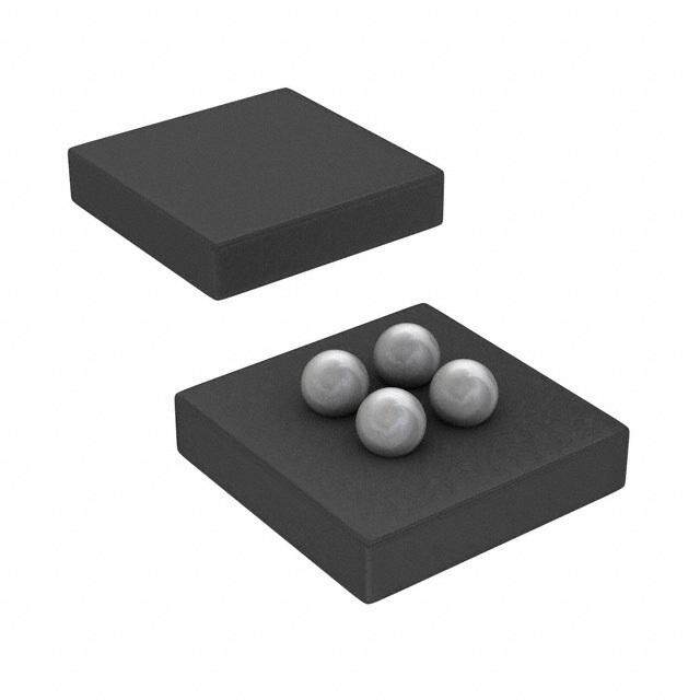
DS18B20U+T&R是Maxim Integrated(现为ADI公司的一部分)生产的一款数字温度传感器,属于DS18B20系列,采用TO-92S封装,支持模拟和数字输出(实际为单总线数字输出),具备高精度测温能力。该型号广泛应用于需要可靠、精确温度监测的场景。

典型应用场景包括:
家用电器:如电冰箱、空调、热水器中用于实时监控内部温度,实现智能温控。
工业控制:在PLC、工业自动化设备或环境监控系统中,用于测量设备或环境温度,确保系统稳定运行。
消费电子:应用于智能插座、温控风扇、加湿器等产品中,提升智能化水平。
医疗设备:用于体温监测仪、恒温培养箱等对温度精度要求较高的医疗辅助设备。
农业与环境监测:部署于温室大棚、养殖场或气象站中,实现长期稳定的温度数据采集。
嵌入式系统与DIY项目:因其单总线接口设计简单、支持多点组网,被广泛用于Arduino、Raspberry Pi等开发平台的温度监测项目。

DS18B20U+T&R具有无需校准、测温范围宽(-55°C至+125°C)、精度高(±0.5°C典型值)、抗干扰能力强等优点,且支持寄生电源模式,布线简便,适合远距离测量。其“+T&R”后缀表示卷带包装,适用于自动化贴片生产,适合批量应用。综上,该传感器在民用、工业及研发领域均有广泛应用价值。
| 参数 | 数值 |
| 产品目录 | 集成电路 (IC)热管理产品 |
| 描述 | IC THERM MICROLAN PROG-RES 8USOP板上安装温度传感器 Prgmble Resolution 1-Wire Parasite Pwr |
| 产品分类 | |
| 品牌 | Maxim Integrated |
| 产品手册 | |
| 产品图片 |
|
| rohs | 符合RoHS无铅 / 符合限制有害物质指令(RoHS)规范要求 |
| 产品系列 | 板上安装温度传感器,Maxim Integrated DS18B20U+T&R- |
| 数据手册 | |
| 产品型号 | DS18B20U+T&R |
| 产品培训模块 | http://www.digikey.cn/PTM/IndividualPTM.page?site=cn&lang=zhs&ptm=24956http://www.digikey.cn/PTM/IndividualPTM.page?site=cn&lang=zhs&ptm=25703http://www.digikey.cn/PTM/IndividualPTM.page?site=cn&lang=zhs&ptm=25705 |
| 产品种类 | 板上安装温度传感器 |
| 传感器类型 | 内部 |
| 供应商器件封装 | 8-uMAX |
| 关闭 | No Shutdown |
| 其它名称 | DS18B20U+T&RCT |
| 准确性 | +/- 2 C |
| 功能 | 温度计,恒温计 |
| 包装 | 剪切带 (CT) |
| 商标 | Maxim Integrated |
| 安装类型 | 表面贴装 |
| 安装风格 | SMD/SMT |
| 封装 | Reel |
| 封装/外壳 | 8-TSSOP,8-MSOP(0.118",3.00mm 宽) |
| 封装/箱体 | MSOP-8 |
| 工作温度 | -55°C ~ 125°C |
| 工厂包装数量 | 3000 |
| 应用说明 | 点击此处下载产品Datasheet点击此处下载产品Datasheet点击此处下载产品Datasheet点击此处下载产品Datasheet点击此处下载产品Datasheet点击此处下载产品Datasheet点击此处下载产品Datasheet点击此处下载产品Datasheet点击此处下载产品Datasheet点击此处下载产品Datasheet点击此处下载产品Datasheet点击此处下载产品Datasheet点击此处下载产品Datasheet点击此处下载产品Datasheet点击此处下载产品Datasheet点击此处下载产品Datasheet点击此处下载产品Datasheet点击此处下载产品Datasheet点击此处下载产品Datasheet点击此处下载产品Datasheet点击此处下载产品Datasheet点击此处下载产品Datasheet点击此处下载产品Datasheet点击此处下载产品Datasheet |
| 感应温度 | -55°C ~ 125°C |
| 拓扑 | 寄存器库,变签式暂存器 |
| 数字输出-位数 | 12 bit |
| 数字输出-总线接口 | 1-Wire |
| 最大工作温度 | + 125 C |
| 最小工作温度 | - 55 C |
| 标准包装 | 1 |
| 温度阈值 | Programmable |
| 电压-电源 | 3 V ~ 5.5 V |
| 电源电压-最大 | 5.5 V |
| 电源电压-最小 | 3 V |
| 电源电流 | 1.5 mA |
| 精度 | ±2°C(最大) |
| 系列 | DS18B20 |
| 设备功能 | Sensor |
| 输出报警 | 是 |
| 输出类型 | 1-Wire® |
| 输出风扇 | 无 |
| 配置 | Local |
| 零件号别名 | 90-18B20+UTR DS18B20U |


- 商务部:美国ITC正式对集成电路等产品启动337调查
- 曝三星4nm工艺存在良率问题 高通将骁龙8 Gen1或转产台积电
- 太阳诱电将投资9.5亿元在常州建新厂生产MLCC 预计2023年完工
- 英特尔发布欧洲新工厂建设计划 深化IDM 2.0 战略
- 台积电先进制程称霸业界 有大客户加持明年业绩稳了
- 达到5530亿美元!SIA预计今年全球半导体销售额将创下新高
- 英特尔拟将自动驾驶子公司Mobileye上市 估值或超500亿美元
- 三星加码芯片和SET,合并消费电子和移动部门,撤换高东真等 CEO
- 三星电子宣布重大人事变动 还合并消费电子和移动部门
- 海关总署:前11个月进口集成电路产品价值2.52万亿元 增长14.8%


PDF Datasheet 数据手册内容提取
Click here for production status of specific part numbers. DS18B20 Programmable Resolution 1-Wire Digital Thermometer General Description Benefits and Features The DS18B20 digital thermometer provides 9-bit to ● Unique 1-Wire® Interface Requires Only One Port 12-bit Celsius temperature measurements and has an Pin for Communication alarm function with nonvolatile user-programmable upper ● Reduce Component Count with Integrated and lower trigger points. The DS18B20 communicates Temperature Sensor and EEPROM over a 1-Wire bus that by definition requires only one • Measures Temperatures from -55°C to +125°C data line (and ground) for communication with a central (-67°F to +257°F) microprocessor. In addition, the DS18B20 can derive • ±0.5°C Accuracy from -10°C to +85°C power directly from the data line (“parasite power”), • Programmable Resolution from 9 Bits to 12 Bits eliminating the need for an external power supply. • No External Components Required Each DS18B20 has a unique 64-bit serial code, which ● Parasitic Power Mode Requires Only 2 Pins for allows multiple DS18B20s to function on the same 1-Wire Operation (DQ and GND) bus. Thus, it is simple to use one microprocessor to ● Simplifies Distributed Temperature-Sensing control many DS18B20s distributed over a large area. Applications with Multidrop Capability Applications that can benefit from this feature include • Each Device Has a Unique 64-Bit Serial Code HVAC environmental controls, temperature monitoring Stored in On-Board ROM systems inside buildings, equipment, or machinery, and process monitoring and control systems. ● Flexible User-Definable Nonvolatile (NV) Alarm Settings with Alarm Search Command Identifies Devices with Applications Temperatures Outside Programmed Limits ● Thermostatic Controls ● Available in 8-Pin SO (150 mils), 8-Pin µSOP, and ● Industrial Systems 3-Pin TO-92 Packages ● Consumer Products ● Thermometers Pin Configurations ● Thermally Sensitive Systems TOP VIEW + N.C. 1 8 N.C. DS18B20 N.C. 2 DS18B20 7 N.C. 1 2 3 VDD 3 6 N.C. DQ 4 5 GND SO (150 mils) (DS18B20Z) DQ 1 + 8 VDD GND DQ VDD N.C. 2 7 N.C. DS18B20 N.C. 3 6 N.C. 1 2 3 GND 4 5 N.C. 1 µSOP BOTTOM VIEW (DS18B20U) Ordering Information appears at end of data sheet. TO-92 (DS18B20) 1-Wire is a registered trademark of Maxim Integrated Products, Inc. 19-7487; Rev 5; 9/18
DS18B20 Programmable Resolution 1-Wire Digital Thermometer Absolute Maximum Ratings Voltage Range on Any Pin Relative to Ground ....-0.5V to +6.0V Storage Temperature Range ............................-55°C to +125°C Operating Temperature Range .........................-55°C to +125°C Solder Temperature ...............................Refer to the IPC/JEDEC J-STD-020 Specification. These are stress ratings only and functional operation of the device at these or any other conditions above those indicated in the operation sections of this specification is not implied. Exposure to absolute maximum rating conditions for extended periods of time may affect reliability. DC Electrical Characteristics (-55°C to +125°C; VDD = 3.0V to 5.5V) PARAMETER SYMBOL CONDITIONS MIN TYP MAX UNITS Supply Voltage VDD Local power (Note 1) +3.0 +5.5 V Parasite power +3.0 +5.5 Pullup Supply Voltage VPU (Notes 1, 2) V Local power +3.0 VDD -10°C to +85°C ±0.5 Thermometer Error tERR -30°C to +100°C (Note 3) ±1 °C -55°C to +125°C ±2 Input Logic-Low VIL (Notes 1, 4, 5) -0.3 +0.8 V Local power +2.2 The lower Input Logic-High VIH (Notes 1,6) of 5.5 or V Parasite power +3.0 VDD + 0.3 Sink Current IL VI/O = 0.4V 4.0 mA Standby Current IDDS (Notes 7, 8) 750 1000 nA Active Current IDD VDD = 5V (Note 9) 1 1.5 mA DQ Input Current IDQ (Note 10) 5 µA Drift (Note 11) ±0.2 °C Note 1: All voltages are referenced to ground. Note 2: The Pullup Supply Voltage specification assumes that the pullup device is ideal, and therefore the high level of the pullup is equal to VPU. In order to meet the VIH spec of the DS18B20, the actual supply rail for the strong pullup transis- tor must include margin for the voltage drop across the transistor when it is turned on; thus: VPU_ACTUAL = VPU_IDEAL + VTRANSISTOR. Note 3: See typical performance curve in Figure 1. Thermometer Error limits are 3-sigma values. Note 4: Logic-low voltages are specified at a sink current of 4mA. Note 5: To guarantee a presence pulse under low voltage parasite power conditions, VILMAX may have to be reduced to as low as 0.5V. Note 6: Logic-high voltages are specified at a source current of 1mA. Note 7: Standby current specified up to +70°C. Standby current typically is 3µA at +125°C. Note 8: To minimize IDDS, DQ should be within the following ranges: GND ≤ DQ ≤ GND + 0.3V or VDD – 0.3V ≤ DQ ≤ VDD. Note 9: Active current refers to supply current during active temperature conversions or EEPROM writes. Note 10: DQ line is high (“high-Z” state). Note 11: Drift data is based on a 1000-hour stress test at +125°C with VDD = 5.5V. www.maximintegrated.com Maxim Integrated │ 2
DS18B20 Programmable Resolution 1-Wire Digital Thermometer AC Electrical Characteristics–NV Memory (-55°C to +125°C; VDD = 3.0V to 5.5V) PARAMETER SYMBOL CONDITIONS MIN TYP MAX UNITS NV Write Cycle Time tWR 2 10 ms EEPROM Writes NEEWR -55°C to +55°C 50k writes EEPROM Data Retention tEEDR -55°C to +55°C 10 years AC Electrical Characteristics (-55°C to +125°C; VDD = 3.0V to 5.5V) PARAMETER SYMBOL CONDITIONS MIN TYP MAX UNITS 9-bit resolution 93.75 10-bit resolution 187.5 Temperature Conversion Time tCONV (Note 12) ms 11-bit resolution 375 12-bit resolution 750 Time to Strong Pullup On tSPON Start convert T command issued 10 µs Time Slot tSLOT (Note 12) 60 120 µs Recovery Time tREC (Note 12) 1 µs Write 0 Low Time tLOW0 (Note 12) 60 120 µs Write 1 Low Time tLOW1 (Note 12) 1 15 µs Read Data Valid tRDV (Note 12) 15 µs Reset Time High tRSTH (Note 12) 480 µs Reset Time Low tRSTL (Notes 12, 13) 480 µs Presence-Detect High tPDHIGH (Note 12) 15 60 µs Presence-Detect Low tPDLOW (Note 12) 60 240 µs Capacitance CIN/OUT 25 pF Note 12: See the timing diagrams in Figure 2. Note 13: Under parasite power, if tRSTL > 960µs, a power-on reset can occur. DS18B20 TYPICAL ERROR CURVE 0.5 0.4 OR (°C) 00..32 +3s ERROR R R 0.1 E ER 0 T ME -0.1 O -3s ERROR M -0.2 R THE -0.3 MEAN ERROR -0.4 -0.5 0 10 20 30 40 50 60 70 TEMPERATURE (°C) Figure 1. Typical Performance Curve www.maximintegrated.com Maxim Integrated │ 3
DS18B20 Programmable Resolution 1-Wire Digital Thermometer 1-WIRE WRITE ZERO TIME SLOT tSLOT tREC START OF NEXT CYCLE tLOW0 1-WIRE READ ZERO TIME SLOT tSLOT START OF NEXT CYCLE tREC tRDV 1-WIRE RESET PULSE RESET PULSE FROM HOST tRSTL tRSTH PRESENCE DETECT 1-WIRE PRESENCE DETECT tPDIH tPDLOW Figure 2. Timing Diagrams Pin Description PIN NAME FUNCTION SO µSOP TO-92 1, 2, 6, 2, 3, 5, — N.C. No Connection 7, 8 6, 7 3 8 3 VDD Optional VDD. VDD must be grounded for operation in parasite power mode. Data Input/Output. Open-drain 1-Wire interface pin. Also provides power to the 4 1 2 DQ device when used in parasite power mode (see the Powering the DS18B20 section.) 5 4 1 GND Ground www.maximintegrated.com Maxim Integrated │ 4
DS18B20 Programmable Resolution 1-Wire Digital Thermometer Overview DQ pin when the bus is high. The high bus signal also Figure 3 shows a block diagram of the DS18B20, and charges an internal capacitor (CPP), which then supplies power to the device when the bus is low. This method of pin descriptions are given in the Pin Description table. deriving power from the 1-Wire bus is referred to as “para- The 64-bit ROM stores the device’s unique serial code. site power.” As an alternative, the DS18B20 may also be The scratchpad memory contains the 2-byte temperature register that stores the digital output from the temperature powered by an external supply on VDD. sensor. In addition, the scratchpad provides access to the Operation—Measuring Temperature 1-byte upper and lower alarm trigger registers (TH and TL) and the 1-byte configuration register. The configura- The core functionality of the DS18B20 is its direct-to- tion register allows the user to set the resolution of the digital temperature sensor. The resolution of the tempera- temperature-to-digital conversion to 9, 10, 11, or 12 bits. ture sensor is user-configurable to 9, 10, 11, or 12 bits, The TH, TL, and configuration registers are nonvolatile corresponding to increments of 0.5°C, 0.25°C, 0.125°C, (EEPROM), so they will retain data when the device is and 0.0625°C, respectively. The default resolution at powered down. power-up is 12-bit. The DS18B20 powers up in a low- power idle state. To initiate a temperature measurement The DS18B20 uses Maxim’s exclusive 1-Wire bus proto- and A-to-D conversion, the master must issue a Convert col that implements bus communication using one control T [44h] command. Following the conversion, the resulting signal. The control line requires a weak pullup resistor thermal data is stored in the 2-byte temperature register since all devices are linked to the bus via a 3-state or in the scratchpad memory and the DS18B20 returns to its open-drain port (the DQ pin in the case of the DS18B20). idle state. If the DS18B20 is powered by an external sup- In this bus system, the microprocessor (the master ply, the master can issue “read time slots” (see the 1-Wire device) identifies and addresses devices on the bus Bus System section) after the Convert T command and using each device’s unique 64-bit code. Because each the DS18B20 will respond by transmitting 0 while the tem- device has a unique code, the number of devices that perature conversion is in progress and 1 when the con- can be addressed on one bus is virtually unlimited. The version is done. If the DS18B20 is powered with parasite 1-Wire bus protocol, including detailed explanations of the power, this notification technique cannot be used since commands and “time slots,” is covered in the 1-Wire Bus the bus must be pulled high by a strong pullup during the System section. entire temperature conversion. The bus requirements for Another feature of the DS18B20 is the ability to oper- parasite power are explained in detail in the Powering the ate without an external power supply. Power is instead DS18B20 section. supplied through the 1-Wire pullup resistor through the VPU MEMORY 4.7kΩ PARASITE POWER CIRCUIT CONTROL LOGIC DS18B20 DQ TEMPERATURE SENSOR GND INTERNAL VDD 64-BIT ROM ALARM HIGH TRIGGER (TH) REGISTER (EEPROM) AND 1-Wire CPP PORT SCRATCHPAD ALARM LOW TRIGGER (TL) REGISTER (EEPROM) VDD POWER- CONFIGURATION SUPPLY SENSE REGISTER (EEPROM) 8-BIT CRC GENERATOR Figure 3. DS18B20 Block Diagram www.maximintegrated.com Maxim Integrated │ 5
DS18B20 Programmable Resolution 1-Wire Digital Thermometer The DS18B20 output temperature data is calibrated in Operation—Alarm Signaling degrees Celsius; for Fahrenheit applications, a lookup After the DS18B20 performs a temperature conversion, table or conversion routine must be used. The tempera- the temperature value is compared to the user-defined ture data is stored as a 16-bit sign-extended two’s comple- two’s complement alarm trigger values stored in the ment number in the temperature register (see Figure 4). 1-byte TH and TL registers (see Figure 5). The sign bit (S) The sign bits (S) indicate if the temperature is positive indicates if the value is positive or negative: for positive or negative: for positive numbers S = 0 and for negative numbers S = 0 and for negative numbers S = 1. The TH numbers S = 1. If the DS18B20 is configured for 12-bit and TL registers are nonvolatile (EEPROM) so they will resolution, all bits in the temperature register will contain retain data when the device is powered down. TH and TL valid data. For 11-bit resolution, bit 0 is undefined. For can be accessed through bytes 2 and 3 of the scratchpad 10-bit resolution, bits 1 and 0 are undefined, and for 9-bit as explained in the Memory section. resolution bits 2, 1, and 0 are undefined. Table 1 gives Only bits 11 through 4 of the temperature register are examples of digital output data and the corresponding temperature reading for 12-bit resolution conversions. used in the TH and TL comparison since TH and TL are 8-bit registers. If the measured temperature is lower than BIT 7 BIT 6 BIT 5 BIT 4 BIT 3 BIT 2 BIT 1 BIT 0 LS BYTE 23 22 21 20 2-1 2-2 2-3 2-4 BIT 15 BIT 14 BIT 13 BIT 12 BIT 11 BIT 10 BIT 9 BIT 8 MS BYTE S S S S S 26 25 24 S = SIGN Figure 4. Temperature Register Format Table 1. Temperature/Data Relationship DIGITAL OUTPUT DIGITAL OUTPUT TEMPERATURE (°C) (BINARY) (HEX) +125 0000 0111 1101 0000 07D0h +85* 0000 0101 0101 0000 0550h +25.0625 0000 0001 1001 0001 0191h +10.125 0000 0000 1010 0010 00A2h +0.5 0000 0000 0000 1000 0008h 0 0000 0000 0000 0000 0000h -0.5 1111 1111 1111 1000 FFF8h -10.125 1111 1111 0101 1110 FF5Eh -25.0625 1111 1110 0110 1111 FE6Fh -55 1111 1100 1001 0000 FC90h *The power-on reset value of the temperature register is +85°C. BIT 7 BIT 6 BIT 5 BIT 4 BIT 3 BIT 2 BIT 1 BIT 0 S 26 25 24 23 22 21 20 Figure 5. TH and TL Register Format www.maximintegrated.com Maxim Integrated │ 6
DS18B20 Programmable Resolution 1-Wire Digital Thermometer or equal to TL or higher than or equal to TH, an alarm con- by CPP. To assure that the DS18B20 has sufficient supply dition exists and an alarm flag is set inside the DS18B20. current, it is necessary to provide a strong pullup on the This flag is updated after every temperature measure- 1-Wire bus whenever temperature conversions are tak- ment; therefore, if the alarm condition goes away, the flag ing place or data is being copied from the scratchpad to will be turned off after the next temperature conversion. EEPROM. This can be accomplished by using a MOSFET to pull the bus directly to the rail as shown in Figure 6. The The master device can check the alarm flag status of 1-Wire bus must be switched to the strong pullup within all DS18B20s on the bus by issuing an Alarm Search 10µs (max) after a Convert T [44h] or Copy Scratchpad [ECh] command. Any DS18B20s with a set alarm flag will [48h] command is issued, and the bus must be held high respond to the command, so the master can determine exactly which DS18B20s have experienced an alarm by the pullup for the duration of the conversion (tCONV) condition. If an alarm condition exists and the TH or TL or data transfer (tWR = 10ms). No other activity can take place on the 1-Wire bus while the pullup is enabled. settings have changed, another temperature conversion should be done to validate the alarm condition. The DS18B20 can also be powered by the conventional method of connecting an external power supply to the Powering the DS18B20 VDD pin, as shown in Figure 7. The advantage of this The DS18B20 can be powered by an external supply on method is that the MOSFET pullup is not required, and the VDD pin, or it can operate in “parasite power” mode, the 1-Wire bus is free to carry other traffic during the tem- which allows the DS18B20 to function without a local perature conversion time. external supply. Parasite power is very useful for applica- The use of parasite power is not recommended for tem- tions that require remote temperature sensing or that are peratures above +100°C since the DS18B20 may not be very space constrained. Figure 3 shows the DS18B20’s able to sustain communications due to the higher leak- parasite-power control circuitry, which “steals” power from age currents that can exist at these temperatures. For the 1-Wire bus via the DQ pin when the bus is high. The applications in which such temperatures are likely, it is stolen charge powers the DS18B20 while the bus is high, strongly recommended that the DS18B20 be powered by and some of the charge is stored on the parasite power an external power supply. capacitor (CPP) to provide power when the bus is low. In some situations the bus master may not know whether When the DS18B20 is used in parasite power mode, the the DS18B20s on the bus are parasite powered or pow- VDD pin must be connected to ground. ered by external supplies. The master needs this informa- In parasite power mode, the 1-Wire bus and CPP can pro- tion to determine if the strong bus pullup should be used vide sufficient current to the DS18B20 for most operations during temperature conversions. To get this information, as long as the specified timing and voltage requirements the master can issue a Skip ROM [CCh] command fol- are met (see the DC Electrical Characteristics and AC lowed by a Read Power Supply [B4h] command followed Electrical Characteristics). However, when the DS18B20 by a “read time slot”. During the read time slot, parasite is performing temperature conversions or copying data powered DS18B20s will pull the bus low, and externally from the scratchpad memory to EEPROM, the operating powered DS18B20s will let the bus remain high. If the current can be as high as 1.5mA. This current can cause bus is pulled low, the master knows that it must supply an unacceptable voltage drop across the weak 1-Wire the strong pullup on the 1-Wire bus during temperature pullup resistor and is more current than can be supplied conversions. VPU DS18B20 DS18B20 VPU GND DQ VDD VPU GND DQ VDD VDD S(EUXPTPELRYN)AL µP µP 4.7kΩ 4.7kΩ 1-Wire BUS TO OTHER 1-Wire BUS TO OTHER 1-Wire DEVICES 1-Wire DEVICES Figure 6. Supplying the Parasite-Powered DS18B20 During Figure 7. Powering the DS18B20 with an External Supply Temperature Conversions www.maximintegrated.com Maxim Integrated │ 7
DS18B20 Programmable Resolution 1-Wire Digital Thermometer 64-BIT Lasered ROM code ter data, which is explained in detail in the Configuration Register section. Bytes 5, 6, and 7 are reserved for inter- Each DS18B20 contains a unique 64–bit code (see Figure nal use by the device and cannot be overwritten. 8) stored in ROM. The least significant 8 bits of the ROM code contain the DS18B20’s 1-Wire family code: 28h. The Byte 8 of the scratchpad is read-only and contains the next 48 bits contain a unique serial number. The most CRC code for bytes 0 through 7 of the scratchpad. significant 8 bits contain a cyclic redundancy check (CRC) The DS18B20 generates this CRC using the method byte that is calculated from the first 56 bits of the ROM described in the CRC Generation section. code. A detailed explanation of the CRC bits is provided Data is written to bytes 2, 3, and 4 of the scratchpad using in the CRC Generation section. The 64-bit ROM code and the Write Scratchpad [4Eh] command; the data must be associated ROM function control logic allow the DS18B20 transmitted to the DS18B20 starting with the least signifi- to operate as a 1-Wire device using the protocol detailed cant bit of byte 2. To verify data integrity, the scratchpad in the 1-Wire Bus System section. can be read (using the Read Scratchpad [BEh] command) after the data is written. When reading the scratchpad, Memory data is transferred over the 1-Wire bus starting with the The DS18B20’s memory is organized as shown in Figure least significant bit of byte 0. To transfer the TH, TL and 9. The memory consists of an SRAM scratchpad with configuration data from the scratchpad to EEPROM, the nonvolatile EEPROM storage for the high and low alarm master must issue the Copy Scratchpad [48h] command. trigger registers (TH and TL) and configuration register. Data in the EEPROM registers is retained when the Note that if the DS18B20 alarm function is not used, device is powered down; at power-up the EEPROM data the TH and TL registers can serve as general-purpose is reloaded into the corresponding scratchpad locations. memory. All memory commands are described in detail in Data can also be reloaded from EEPROM to the scratch- the DS18B20 Function Commands section. pad at any time using the Recall E2 [B8h] command. The Byte 0 and byte 1 of the scratchpad contain the LSB and master can issue read time slots following the Recall E2 the MSB of the temperature register, respectively. These command and the DS18B20 will indicate the status of the bytes are read-only. Bytes 2 and 3 provide access to TH recall by transmitting 0 while the recall is in progress and and TL registers. Byte 4 contains the configuration regis- 1 when the recall is done. 8-BIT CRC 48-BIT SERIAL NUMBER 8-BIT FAMILY CODE (28h) MSB LSB MSB LSB MSB LSB Figure 8. 64-Bit Lasered ROM Code SCRATCHPAD (POWER-UP STATE) BYTE 0 TEMPERATURE LSB (50h) (85°C) BYTE 1 TEMPERATURE MSB (05h) EEPROM BYTE 2 TH REGISTER OR USER BYTE 1* TH REGISTER OR USER BYTE 1* BYTE 3 TL REGISTER OR USER BYTE 2* TL REGISTER OR USER BYTE 2* BYTE 4 CONFIGURATION REGISTER* CONFIGURATION REGISTER* BYTE 5 RESERVED (FFh) BYTE 6 RESERVED BYTE 7 RESERVED (10h) BYTE 8 CRC* *POWER-UP STATE DEPENDS ON VALUE(S) STORED IN EEPROM. Figure 9. DS18B20 Memory Map www.maximintegrated.com Maxim Integrated │ 8
DS18B20 Programmable Resolution 1-Wire Digital Thermometer Configuration Register received error free. The comparison of CRC values and the decision to continue with an operation are determined Byte 4 of the scratchpad memory contains the configura- entirely by the bus master. There is no circuitry inside the tion register, which is organized as illustrated in Figure 10. DS18B20 that prevents a command sequence from pro- The user can set the conversion resolution of the DS18B20 ceeding if the DS18B20 CRC (ROM or scratchpad) does using the R0 and R1 bits in this register as shown in Table not match the value generated by the bus master. 2. The power-up default of these bits is R0 = 1 and R1 = 1 (12-bit resolution). Note that there is a direct tradeoff The equivalent polynomial function of the CRC (ROM or between resolution and conversion time. Bit 7 and bits 0 to scratchpad) is: 4 in the configuration register are reserved for internal use CRC = X8 + X5 + X4 + 1 by the device and cannot be overwritten. The bus master can re-calculate the CRC and compare it CRC Generation to the CRC values from the DS18B20 using the polyno- mial generator shown in Figure 11. This circuit consists CRC bytes are provided as part of the DS18B20’s 64-bit of a shift register and XOR gates, and the shift register ROM code and in the 9th byte of the scratchpad memory. bits are initialized to 0. Starting with the least significant The ROM code CRC is calculated from the first 56 bits bit of the ROM code or the least significant bit of byte 0 of the ROM code and is contained in the most significant in the scratchpad, one bit at a time should shifted into the byte of the ROM. The scratchpad CRC is calculated from shift register. After shifting in the 56th bit from the ROM or the data stored in the scratchpad, and therefore it chang- the most significant bit of byte 7 from the scratchpad, the es when the data in the scratchpad changes. The CRCs polynomial generator will contain the recalculated CRC. provide the bus master with a method of data validation Next, the 8-bit ROM code or scratchpad CRC from the when data is read from the DS18B20. To verify that data DS18B20 must be shifted into the circuit. At this point, if has been read correctly, the bus master must re-calculate the re-calculated CRC was correct, the shift register will the CRC from the received data and then compare this contain all 0s. Additional information about the Maxim value to either the ROM code CRC (for ROM reads) or 1-Wire cyclic redundancy check is available in Application to the scratchpad CRC (for scratchpad reads). If the cal- Note 27: Understanding and Using Cyclic Redundancy culated CRC matches the read CRC, the data has been Checks with Maxim iButton Products. BIT 7 BIT 6 BIT 5 BIT 4 BIT 3 BIT 2 BIT 1 BIT 0 0 R1 R0 1 1 1 1 1 Figure 10. Configuration Register Table 2. Thermometer Resolution Configuration RESOLUTION R1 R0 MAX CONVERSION TIME (BITS) 0 0 9 93.75ms (tCONV/8) 0 1 10 187.5ms (tCONV/4) 1 0 11 375ms (tCONV/2) 1 1 12 750ms (tCONV) INPUT XOR XOR XOR MSB LSB Figure 11. CRC Generator www.maximintegrated.com Maxim Integrated │ 9
DS18B20 Programmable Resolution 1-Wire Digital Thermometer 1-Wire Bus System Transaction Sequence The 1-Wire bus system uses a single bus master to con- The transaction sequence for accessing the DS18B20 is trol one or more slave devices. The DS18B20 is always a as follows: slave. When there is only one slave on the bus, the sys- Step 1. Initialization tem is referred to as a “single-drop” system; the system is Step 2. ROM Command (followed by any required data “multidrop” if there are multiple slaves on the bus. exchange) All data and commands are transmitted least significant Step 3. DS18B20 Function Command (followed by any bit first over the 1-Wire bus. required data exchange) The following discussion of the 1-Wire bus system is It is very important to follow this sequence every time the broken down into three topics: hardware configuration, DS18B20 is accessed, as the DS18B20 will not respond transaction sequence, and 1-Wire signaling (signal types if any steps in the sequence are missing or out of order. and timing). Exceptions to this rule are the Search ROM [F0h] and Hardware Configuration Alarm Search [ECh] commands. After issuing either of these ROM commands, the master must return to Step 1 The 1-Wire bus has by definition only a single data line. in the sequence. Each device (master or slave) interfaces to the data line via an open-drain or 3-state port. This allows each device Initialization to “release” the data line when the device is not transmit- All transactions on the 1-Wire bus begin with an initializa- ting data so the bus is available for use by another device. tion sequence. The initialization sequence consists of a The 1-Wire port of the DS18B20 (the DQ pin) is open reset pulse transmitted by the bus master followed by drain with an internal circuit equivalent to that shown in presence pulse(s) transmitted by the slave(s). The pres- Figure 12. ence pulse lets the bus master know that slave devices The 1-Wire bus requires an external pullup resistor of (such as the DS18B20) are on the bus and are ready approximately 5kΩ; thus, the idle state for the 1-Wire to operate. Timing for the reset and presence pulses is bus is high. If for any reason a transaction needs to be detailed in the 1-Wire Signaling section. suspended, the bus MUST be left in the idle state if the transaction is to resume. Infinite recovery time can occur ROM Commands between bits so long as the 1-Wire bus is in the inactive After the bus master has detected a presence pulse, it (high) state during the recovery period. If the bus is held can issue a ROM command. These commands operate low for more than 480µs, all components on the bus will on the unique 64-bit ROM codes of each slave device be reset. and allow the master to single out a specific device if many are present on the 1-Wire bus. These commands also allow the master to determine how many and what types of devices are present on the bus or if any device VPU has experienced an alarm condition. There are five ROM commands, and each command is 8 bits long. The master DS18B20 4.7kΩ device must issue an appropriate ROM command before 1-Wire PORT issuing a DS18B20 function command. A flowchart for Rx 1-Wire BUS DQ Rx operation of the ROM commands is shown in Figure 13. 5µA Tx Search Rom [F0h] TYP 100Ω MOSFET When a system is initially powered up, the master must Tx identify the ROM codes of all slave devices on the bus, Rx = RECEIVE which allows the master to determine the number of Tx = TRANSMIT slaves and their device types. The master learns the ROM codes through a process of elimination that requires the master to perform a Search ROM cycle (i.e., Search Figure 12. Hardware Configuration ROM command followed by data exchange) as many times as necessary to identify all of the slave devices. www.maximintegrated.com Maxim Integrated │ 10
DS18B20 Programmable Resolution 1-Wire Digital Thermometer If there is only one slave on the bus, the simpler Read master must return to Step 1 (Initialization) in the transac- ROM [33h] command can be used in place of the Search tion sequence. See the Operation—Alarm Signaling sec- ROM process. For a detailed explanation of the Search tion for an explanation of alarm flag operation. ROM procedure, refer to Application Note 937: Book of iButton® Standards. After every Search ROM cycle, the DS18B20 Function Commands bus master must return to Step 1 (Initialization) in the After the bus master has used a ROM command to transaction sequence. address the DS18B20 with which it wishes to communi- cate, the master can issue one of the DS18B20 function Read Rom [33h] commands. These commands allow the master to write This command can only be used when there is one slave to and read from the DS18B20’s scratchpad memory, on the bus. It allows the bus master to read the slave’s initiate temperature conversions and determine the power 64-bit ROM code without using the Search ROM proce- supply mode. The DS18B20 function commands, which dure. If this command is used when there is more than are described below, are summarized in Table 3 and illus- one slave present on the bus, a data collision will occur trated by the flowchart in Figure 14. when all the slaves attempt to respond at the same time. Convert T [44h] Match Rom [55H] This command initiates a single temperature conversion. The match ROM command followed by a 64-bit ROM Following the conversion, the resulting thermal data is code sequence allows the bus master to address a stored in the 2-byte temperature register in the scratch- specific slave device on a multidrop or single-drop bus. pad memory and the DS18B20 returns to its low-power Only the slave that exactly matches the 64-bit ROM code idle state. If the device is being used in parasite power sequence will respond to the function command issued mode, within 10µs (max) after this command is issued by the master; all other slaves on the bus will wait for a the master must enable a strong pullup on the 1-Wire bus reset pulse. for the duration of the conversion (tCONV) as described in the Powering the DS18B20 section. If the DS18B20 is Skip Rom [CCh] powered by an external supply, the master can issue read The master can use this command to address all devices time slots after the Convert T command and the DS18B20 on the bus simultaneously without sending out any ROM will respond by transmitting a 0 while the temperature code information. For example, the master can make all conversion is in progress and a 1 when the conversion is DS18B20s on the bus perform simultaneous temperature done. In parasite power mode this notification technique conversions by issuing a Skip ROM command followed by cannot be used since the bus is pulled high by the strong a Convert T [44h] command. pullup during the conversion. Note that the Read Scratchpad [BEh] command can follow the Skip ROM command only if there is a single Write Scratchpad [4Eh] slave device on the bus. In this case, time is saved by This command allows the master to write 3 bytes of data allowing the master to read from the slave without send- to the DS18B20’s scratchpad. The first data byte is written ing the device’s 64-bit ROM code. A Skip ROM command into the TH register (byte 2 of the scratchpad), the second followed by a Read Scratchpad command will cause byte is written into the TL register (byte 3), and the third a data collision on the bus if there is more than one byte is written into the configuration register (byte 4). Data slave since multiple devices will attempt to transmit data must be transmitted least significant bit first. All three simultaneously. bytes MUST be written before the master issues a reset, or the data may be corrupted. Alarm Search [ECh] The operation of this command is identical to the operation Read Scratchpad [BEh] of the Search ROM command except that only slaves with This command allows the master to read the contents of a set alarm flag will respond. This command allows the the scratchpad. The data transfer starts with the least sig- master device to determine if any DS18B20s experienced nificant bit of byte 0 and continues through the scratchpad an alarm condition during the most recent temperature until the 9th byte (byte 8 – CRC) is read. The master may conversion. After every Alarm Search cycle (i.e., Alarm issue a reset to terminate reading at any time if only part Search command followed by data exchange), the bus of the scratchpad data is needed. iButton is a registered trademark of Maxim Integrated Products, Inc. www.maximintegrated.com Maxim Integrated │ 11
DS18B20 Programmable Resolution 1-Wire Digital Thermometer Copy Scratchpad [48h] following the Recall E2 command and the DS18B20 will indicate the status of the recall by transmitting 0 while the This command copies the contents of the scratchpad recall is in progress and 1 when the recall is done. The TH, TL and configuration registers (bytes 2, 3 and 4) to recall operation happens automatically at power-up, so EEPROM. If the device is being used in parasite power valid data is available in the scratchpad as soon as power mode, within 10µs (max) after this command is issued the is applied to the device. master must enable a strong pullup on the 1-Wire bus for at least 10ms as described in the Powering the DS18B20 Read Power Supply [B4h] section. The master device issues this command followed by a Recall E2 [B8h] read time slot to determine if any DS18B20s on the bus are using parasite power. During the read time slot, para- This command recalls the alarm trigger values (TH and site powered DS18B20s will pull the bus low, and exter- TL) and configuration data from EEPROM and places the nally powered DS18B20s will let the bus remain high. See data in bytes 2, 3, and 4, respectively, in the scratchpad the Powering the DS18B20 section for usage information memory. The master device can issue read time slots for this command. Table 3. DS18B20 Function Command Set 1-Wire BUS ACTIVITY AFTER COMMAND DESCRIPTION PROTOCOL NOTES COMMAND IS ISSUED TEMPERATURE CONVERSION COMMANDS DS18B20 transmits conversion status Convert T Initiates temperature conversion. 44h to master (not applicable for parasite- 1 powered DS18B20s). MEMORY COMMANDS Read Reads the entire scratchpad including the DS18B20 transmits up to 9 data bytes BEh 2 Scratchpad CRC byte. to master. Write Writes data into scratchpad bytes 2, 3, and Master transmits 3 data bytes to 4Eh 3 Scratchpad 4 (TH, TL, and configuration registers). DS18B20. Copy Copies TH, TL, and configuration register 48h None 1 Scratchpad data from the scratchpad to EEPROM. Recall E2 Recalls TH, TL, and configuration register B8h DS18B20 transmits recall status to data from EEPROM to the scratchpad. master. Read Power Signals DS18B20 power supply mode to DS18B20 transmits supply status to B4h Supply the master. master. Note 1: For parasite-powered DS18B20s, the master must enable a strong pullup on the 1-Wire bus during temperature conver- sions and copies from the scratchpad to EEPROM. No other bus activity may take place during this time. Note 2: The master can interrupt the transmission of data at any time by issuing a reset. Note 3: All three bytes must be written before a reset is issued. www.maximintegrated.com Maxim Integrated │ 12
DS18B20 Programmable Resolution 1-Wire Digital Thermometer MASTER Tx RESET PULSE INITIALIZATION SEQUENCE DS18B20 Tx PRESENCE PULSE MASTER Tx ROM COMMAND 33h READ N 55h MATCH N F0h N ECh N CCh N ROM ROM SEARCH ROM ALARM SEARCH SKIP ROM COMMAND COMMAND COMMAND COMMAND COMMAND Y Y Y Y Y DS18B20 Tx BIT 0 DS18B20 Tx BIT 0 MASTER Tx BIT 0 DS18B20 Tx BIT 0 DS18B20 Tx BIT 0 MASTER Tx BIT 0 MASTER TX BIT 0 BIT 0 N N BIT 0 N DEVICE(S) N WITH ALARM MATCH ? MATCH ? FLAG SET ? DS18B20 TX Y Y Y FAMILY CODE 1 BYTE DS18B20 Tx BIT 1 MASTER Tx DS18B20 Tx BIT 1 DS18B20 Tx BIT 1 SERIAL NUMBER MASTER Tx BIT 1 6 BYTES DS18B20 Tx CRC BYTE BIT 1 N N BIT 1 MATCH? MATCH? Y Y DS18B20 Tx BIT 63 MASTER Tx BIT 63 DS18B20 Tx BIT 63 MASTER Tx BIT 63 BIT 63 N N BIT 63 MATCH? MATCH? Y Y MASTER Tx FUNCTION COMMAND (FIGURE 14) Figure 13. ROM Commands Flowchart www.maximintegrated.com Maxim Integrated │ 13
DS18B20 Programmable Resolution 1-Wire Digital Thermometer MASTER Tx 44h CONVERT N 48h COPY N FUNCTION COMMAND TEMPERATURE ? SCRATCHPAD ? Y Y N PARASITE Y N PARASITE Y POWER ? POWER ? DS18B20 BEGINS CONVERSION MASTER ENABLES STRONG MASTER ENABLES STRONG PULL-UP ON DQ PULL-UP ON DQ DEVICE CONVERTING N DS18B20 CONVERTS COPY IN N DATA COPIED FROM TEMPERATURE ? TEMPERATURE PROGRESS ? SCRATCHPAD TO EEPROM Y MASTER DISABLES Y MASTER DISABLES STRONG PULLUP STRONG PULLUP MASTER MASTER MASTER MASTER Rx “0s” Rx “1s” Rx “0s” Rx “1s” N B4h READ N B8h N BEh READ N 4Eh WRITE POWER SUPPLY ? RECALL E2 ? SCRATCHPAD ? SCRATCHPAD ? Y Y Y Y MASTER BEGINS N PARASITE Y DATA RECALL FROM MASTER Rx DATA POWER ? E2 PROM SBCYRTAET CFHRPOAMD MASTSECRR TAxT CTHH BPYATDE TO MASTER MASTER Rx “1s” Rx “0s” DEVICE BUSY N MASTER Tx Y MASTSECRR ATTx CTHL PBAYDTE TO RECALLING RESET ? DATA ? Y N MASTER TX CONFIG. BYTE TO SCRATCHPAD MASTER MASTER Rx “0s” Rx “1s” N HAVE 8 BYTES BEEN READ ? Y MASTER Rx SCRATCHPAD CRC BYTE RETURN TO INITIALIZATION SEQUENCE (FIGURE 13) FOR NEXT TRANSACTION Figure 14. DS18B20 Function Commands Flowchart www.maximintegrated.com Maxim Integrated │ 14
DS18B20 Programmable Resolution 1-Wire Digital Thermometer 1-Wire Signaling Read/Write Time Slots The DS18B20 uses a strict 1-Wire communication pro- The bus master writes data to the DS18B20 during write tocol to ensure data integrity. Several signal types are time slots and reads data from the DS18B20 during read defined by this protocol: reset pulse, presence pulse, write time slots. One bit of data is transmitted over the 1-Wire 0, write 1, read 0, and read 1. The bus master initiates all bus per time slot. these signals, with the exception of the presence pulse. Write Time Slots Initialization Procedure—Reset And There are two types of write time slots: “Write 1” time slots Presence Pulses and “Write 0” time slots. The bus master uses a Write 1 time slot to write a logic 1 to the DS18B20 and a Write All communication with the DS18B20 begins with an ini- 0 time slot to write a logic 0 to the DS18B20. All write tialization sequence that consists of a reset pulse from the time slots must be a minimum of 60µs in duration with a master followed by a presence pulse from the DS18B20. minimum of a 1µs recovery time between individual write This is illustrated in Figure 15. When the DS18B20 sends slots. Both types of write time slots are initiated by the the presence pulse in response to the reset, it is indicating master pulling the 1-Wire bus low (see Figure 14). to the master that it is on the bus and ready to operate. To generate a Write 1 time slot, after pulling the 1-Wire During the initialization sequence the bus master trans- bus low, the bus master must release the 1-Wire bus mits (TX) the reset pulse by pulling the 1-Wire bus low within 15µs. When the bus is released, the 5kΩ pullup for a minimum of 480µs. The bus master then releases resistor will pull the bus high. To generate a Write 0 time the bus and goes into receive mode (RX). When the bus slot, after pulling the 1-Wire bus low, the bus master must is released, the 5kΩ pullup resistor pulls the 1-Wire bus continue to hold the bus low for the duration of the time high. When the DS18B20 detects this rising edge, it waits slot (at least 60µs). 15µs to 60µs and then transmits a presence pulse by pull- ing the 1-Wire bus low for 60µs to 240µs. The DS18B20 samples the 1-Wire bus during a window that lasts from 15µs to 60µs after the master initiates the write time slot. If the bus is high during the sampling win- dow, a 1 is written to the DS18B20. If the line is low, a 0 is written to the DS18B20. MASTER Tx RESET PULSE MASTER Rx 480µs MINIMUM 480µs MINIMUM DS18B20 WAITS 15-60µ s DS18B20 TX PRESENCE PULSE 60-240µS VPU 1-Wire BUS GND LINE TYPE LEGEND BUS MASTER PULLING LOW DS18B20 PULLING LOW RESISTOR PULLUP Figure 15. Initialization Timing www.maximintegrated.com Maxim Integrated │ 15
DS18B20 Programmable Resolution 1-Wire Digital Thermometer START START OF SLOT OF SLOT MASTER WRITE “0” SLOT 1µs < TREC < ∞ MASTER WRITE “1” SLOT 60µs < Tx “0” < 120µs 1µs VPU 1-Wire BUS GND DS18B20 SAMPLES DS18B20 SAMPLES MIN TYP MAX MIN TYP MAX 15µs 15µs 30µs 15µs 15µs 30µs MASTER READ “0” SLOT MASTER READ “1” SLOT 1µs < TREC < ∞ VPU 1-Wire BUS GND MASTER SAMPLES > 1µs MASTER SAMPLES > 1µs 15µs 45µs 15µs LINE TYPE LEGEND BUS MASTER PULLING LOW DS18B20 PULLING LOW RESISTOR PULLUP Figure 16. Read/Write Time Slot Timing Diagram Read Time Slots read time slot, the DS18B20 will begin transmitting a 1 or 0 on bus. The DS18B20 transmits a 1 by leaving the The DS18B20 can only transmit data to the master when bus high and transmits a 0 by pulling the bus low. When the master issues read time slots. Therefore, the master transmitting a 0, the DS18B20 will release the bus by the must generate read time slots immediately after issuing end of the time slot, and the bus will be pulled back to a Read Scratchpad [BEh] or Read Power Supply [B4h] its high idle state by the pullup resister. Output data from command, so that the DS18B20 can provide the request- the DS18B20 is valid for 15µs after the falling edge that ed data. In addition, the master can generate read time initiated the read time slot. Therefore, the master must slots after issuing Convert T [44h] or Recall E2 [B8h] com- release the bus and then sample the bus state within mands to find out the status of the operation as explained 15µs from the start of the slot. in the DS18B20 Function Commands section. All read time slots must be a minimum of 60µs in duration Figure 17 illustrates that the sum of TINIT, TRC, and with a minimum of a 1µs recovery time between slots. A TSAMPLE must be less than 15µs for a read time slot. Figure 18 shows that system timing margin is maximized read time slot is initiated by the master device pulling the 1-Wire bus low for a minimum of 1µs and then releasing by keeping TINIT and TRC as short as possible and by locating the master sample time during read time slots the bus (see Figure 16). After the master initiates the towards the end of the 15µs period. www.maximintegrated.com Maxim Integrated │ 16
DS18B20 Programmable Resolution 1-Wire Digital Thermometer VPU VIH OF MASTER 1-Wire BUS GND TINT > 1µs TRC MASTER SAMPLES 15µs Figure 17. Detailed Master Read 1 Timing VPU VIH OF MASTER 1-Wire BUS GND TINT = TRC = SMALL SMALL MASTER SAMPLES 15µs LINE TYPE LEGEND BUS MASTER PULLING LOW RESISTOR PULLUP Figure 18. Recommended Master Read 1 Timing Related Application Notes Application Note 162: Interfacing the DS18x20/DS1822 1-Wire Temperature Sensor in a Microcontroller The following application notes can be Environment applied to the DS18B20 and are available at www.maximintegrated.com. Application Note 208: Curve Fitting the Error of a Bandgap-Based Digital Temperature Sensor Application Note 27: Understanding and Using Cyclic Redundancy Checks with Maxim iButton Products Application Note 2420: 1-Wire Communication with a Microchip PICmicro Microcontroller Application Note 122: Using Dallas’ 1-Wire ICs in 1-Cell Li-Ion Battery Packs with Low-Side N-Channel Safety Application Note 3754: Single-Wire Serial Bus Carries FETs Master Isolated Power and Data Application Note 126: 1-Wire Communication Through Sample 1-Wire subroutines that can be used in conjunc- Software tion with Application Note 74: Reading and Writing iBut- tons via Serial Interfaces can be downloaded from the Maxim website. www.maximintegrated.com Maxim Integrated │ 17
DS18B20 Programmable Resolution 1-Wire Digital Thermometer DS18B20 Operation Example 1 DS18B20 Operation Example 2 In this example there are multiple DS18B20s on the bus In this example there is only one DS18B20 on the bus and and they are using parasite power. The bus master initi- it is using parasite power. The master writes to the TH, TL, ates a temperature conversion in a specific DS18B20 and and configuration registers in the DS18B20 scratchpad then reads its scratchpad and recalculates the CRC to and then reads the scratchpad and recalculates the CRC verify the data. to verify the data. The master then copies the scratchpad contents to EEPROM. MASTER DATA COMMENTS MODE (LSB FIRST) MASTER DATA (LSB COMMENTS MODE FIRST) Tx Reset Master issues reset pulse. Tx Reset Master issues reset pulse. DS18B20s respond with Rx Presence presence pulse. DS18B20 responds with Rx Presence presence pulse. Master issues Match ROM Tx 55h command. Master issues Skip ROM Tx CCh command. 64-bit ROM Master sends DS18B20 ROM Tx code code. Master issues Write Scratchpad Tx 4Eh command. Master issues Convert T Tx 44h command. Master sends three data bytes DQ line Master applies strong pullup Tx 3 data bytes to scratchpad (TH, TL, and config). Tx held high by to DQ for the duration of the strong pullup conversion (tCONV). Tx Reset Master issues reset pulse. Tx Reset Master issues reset pulse. DS18B20 responds with Rx Presence presence pulse. DS18B20s respond with Rx Presence presence pulse. Master issues Skip ROM Tx CCh command. Master issues Match ROM Tx 55h command. Master issues Read Scratchpad Tx BEh command. 64-bit ROM Master sends DS18B20 ROM Tx code code. Master reads entire scratchpad Master issues Read Scratchpad including CRC. The master then Tx BEh command. recalculates the CRC of the first eight data bytes from the Master reads entire scratchpad Rx 9 data bytes scratchpad and compares the including CRC. The master then calculated CRC with the read recalculates the CRC of the CRC (byte 9). If they match, first eight data bytes from the the master continues; if not, the Rx 9 data bytes scratchpad and compares the read operation is repeated. calculated CRC with the read CRC (byte 9). If they match, Tx Reset Master issues reset pulse. the master continues; if not, the DS18B20 responds with read operation is repeated. Rx Presence presence pulse. Master issues Skip ROM Tx CCh command. Master issues Copy Scratchpad Tx 48h command. DQ line Master applies strong pullup to Tx held high by DQ for at least 10ms while copy strong pullup operation is in progress. www.maximintegrated.com Maxim Integrated │ 18
DS18B20 Programmable Resolution 1-Wire Digital Thermometer Ordering Information PART TEMP RANGE PIN-PACKAGE TOP MARK DS18B20 -55°C to +125°C 3 TO-92 18B20 DS18B20+ -55°C to +125°C 3 TO-92 18B20 DS18B20/T&R -55°C to +125°C 3 TO-92 (2000 Piece) 18B20 DS18B20+T&R -55°C to +125°C 3 TO-92 (2000 Piece) 18B20 DS18B20-SL/T&R -55°C to +125°C 3 TO-92 (2000 Piece)* 18B20 DS18B20-SL+T&R -55°C to +125°C 3 TO-92 (2000 Piece)* 18B20 DS18B20U -55°C to +125°C 8 FSOP 18B20 DS18B20U+ -55°C to +125°C 8 FSOP 18B20 DS18B20U/T&R -55°C to +125°C 8 FSOP (3000 Piece) 18B20 DS18B20U+T&R -55°C to +125°C 8 FSOP (3000 Piece) 18B20 DS18B20Z -55°C to +125°C 8 SO DS18B20 DS18B20Z+ -55°C to +125°C 8 SO DS18B20 DS18B20Z/T&R -55°C to +125°C 8 SO (2500 Piece) DS18B20 DS18B20Z+T&R -55°C to +125°C 8 SO (2500 Piece) DS18B20 +Denotes a lead-free package. A “+” will appear on the top mark of lead-free packages. T&R = Tape and reel. *TO-92 packages in tape and reel can be ordered with straight or formed leads. Choose “SL” for straight leads. Bulk TO-92 orders are straight leads only. www.maximintegrated.com Maxim Integrated │ 19
DS18B20 Programmable Resolution 1-Wire Digital Thermometer Revision History REVISION PAGES DESCRIPTION DATE CHANGED In the Absolute Maximum Ratings section, removed the reflow oven temperature value of +220°C. 030107 19 Reference to JEDEC specification for reflow remains. In the Operation—Alarm Signaling section, added “or equal to” in the description for a TH alarm 5 condition 101207 In the Memory section, removed incorrect text describing memory. 7 In the Configuration Register section, removed incorrect text describing configuration register. 8 In the Ordering Information table, added TO-92 straight-lead packages and included a note that the 042208 2 TO-92 package in tape and reel can be ordered with either formed or straight leads. 1/15 Updated Benefits and Features section 1 09/18 Updated DC Electrical Characteristics table 2 For pricing, delivery, and ordering information, please visit Maxim Integrated’s online storefront at https://www.maximintegrated.com/en/storefront/storefront.html. Maxim Integrated cannot assume responsibility for use of any circuitry other than circuitry entirely embodied in a Maxim Integrated product. No circuit patent licenses are implied. Maxim Integrated reserves the right to change the circuitry and specifications without notice at any time. The parametric values (min and max limits) shown in the Electrical Characteristics table are guaranteed. Other parametric values quoted in this data sheet are provided for guidance. Maxim Integrated and the Maxim Integrated logo are trademarks of Maxim Integrated Products, Inc. © 2018 Maxim Integrated Products, Inc. │ 20
Mouser Electronics Authorized Distributor Click to View Pricing, Inventory, Delivery & Lifecycle Information: M axim Integrated: DS18B20+ DS18B20+T&R DS18B20-SL+T&R DS18B20U+ DS18B20U+T&R DS18B20Z+ DS18B20Z+T&R DS18B20Z/T&R DS18B20Z