ICGOO在线商城 > 集成电路(IC) > 时钟/计时 - 时钟发生器,PLL,频率合成器 > DS1099U-AG+

 Datasheet下载
- 型号: DS1099U-AG+
- 制造商: Maxim
- 库位|库存: xxxx|xxxx
- 要求:
| 数量阶梯 | 香港交货 | 国内含税 |
| +xxxx | $xxxx | ¥xxxx |
查看当月历史价格
查看今年历史价格
DS1099U-AG+产品简介:
ICGOO电子元器件商城为您提供DS1099U-AG+由Maxim设计生产,在icgoo商城现货销售,并且可以通过原厂、代理商等渠道进行代购。 DS1099U-AG+价格参考¥5.89-¥5.89。MaximDS1099U-AG+封装/规格:时钟/计时 - 时钟发生器,PLL,频率合成器, 。您可以下载DS1099U-AG+参考资料、Datasheet数据手册功能说明书,资料中有DS1099U-AG+ 详细功能的应用电路图电压和使用方法及教程。
Maxim Integrated的DS1099U-AG+是一款时钟发生器芯片,属于时钟/计时类中的时钟发生器、PLL(锁相环)和频率合成器类别。该芯片主要用于生成高精度和稳定的时钟信号,适用于对时钟信号稳定性、精度要求较高的电子系统中。

DS1099U-AG+的典型应用场景包括:

1. 通信设备:如无线基站、路由器和交换机等,用于提供稳定的系统时钟,确保数据传输的同步性和可靠性。

2. 工业控制系统:在工业自动化设备中,为处理器、ADC/DAC模块、通信接口等提供精准的时钟源。

3. 测试与测量仪器:如示波器、频谱分析仪等高精度仪器中,用于生成参考时钟,确保测量精度。

4. 消费类电子产品:如高端音频设备、数字电视等,用于提供低抖动的时钟信号,提升音视频质量。

5. 嵌入式系统与微控制器系统:作为主时钟源或辅助时钟源,为MCU、FPGA、DSP等器件提供可配置的时钟频率。

该芯片采用小型TSSOP封装,支持多种输出频率配置,具备较低的相位抖动和良好的电源噪声抑制能力,适合在空间受限且对性能有要求的应用中使用。
| 参数 | 数值 |
| 产品目录 | 集成电路 (IC)无源元件 |
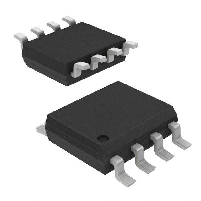
| 描述 | IC ECONOSCILLATOR DL 8-USOP可编程振荡器 Low-Frequency Dual EconOscillator |
| 产品分类 | |
| 品牌 | Maxim Integrated |
| 产品手册 | |
| 产品图片 |
|
| rohs | 符合RoHS无铅 / 符合限制有害物质指令(RoHS)规范要求 |
| 产品系列 | 振荡器,可编程振荡器,Maxim Integrated DS1099U-AG+EconOscillator™ |
| 数据手册 | |
| 产品型号 | DS1099U-AG+ |
| PLL | 无 |
| 产品 | Programmable |
| 产品培训模块 | http://www.digikey.cn/PTM/IndividualPTM.page?site=cn&lang=zhs&ptm=25703http://www.digikey.cn/PTM/IndividualPTM.page?site=cn&lang=zhs&ptm=25705 |
| 产品种类 | |
| 供应商器件封装 | 8-uMAX |
| 其它名称 | DS1099UAG |
| 分频器/倍频器 | 是/无 |
| 包装 | 管件 |
| 占空比-最大 | 55 % |
| 商标 | Maxim Integrated |
| 安装类型 | 表面贴装 |
| 安装风格 | SMD/SMT |
| 封装 | Tube |
| 封装/外壳 | 8-TSSOP,8-MSOP(0.118",3.00mm 宽) |
| 封装/箱体 | UMAX-8 |
| 尺寸 | 3 mm W x 3 mm L x 0.85 mm H |
| 工作温度 | -40°C ~ 125°C |
| 工厂包装数量 | 50 |
| 差分-输入:输出 | 无/无 |
| 应用说明 | |
| 最大工作温度 | + 125 C |
| 最小工作温度 | - 40 C |
| 标准包装 | 1 |
| 比率-输入:输出 | 1:2 |
| 电压-电源 | 2.7 V ~ 5.5 V |
| 电源电压-最大 | 5.5 V |
| 电源电压-最小 | 2.7 V |
| 电路数 | 1 |
| 端接类型 | SMD/SMT |
| 类型 | 时钟发生器 |
| 系列 | DS1099U |
| 输入 | 时钟 |
| 输出 | CMOS,TTL |
| 输出格式 | CMOS, TTL |
| 零件号别名 | 90-1099U+0AG DS1099U |
| 频率 | 1.048 MHz, 16.375 kHz |
| 频率-最大值 | 1.048MHz,16.375kHz |


PDF Datasheet 数据手册内容提取
DS1099 Low-Frequency Dual EconOscillator General Description Features The DS1099 is a low-cost, low-power, low-frequency ● Low-Cost, Low-Frequency EconOscillator™ with silicon oscillator that generates two square-wave out- Dual Outputs puts with frequencies between 0.25Hz and 1.048MHz. ● Factory Programmed Individual output enables allow both outputs to be ● Output Frequencies Independently Programmable enabled/disabled independently. Both outputs are from 0.25Hz to 1.048MHz capable of sinking 16mA, allowing them to directly interface to light-emitting diodes (LEDs) as well as other ● 2.7V to 5.5V Single-Supply Operation external circuitry. The DS1099 operates over a wide ● No External Timing Components Required supply voltage, making it suitable for both 3V and 5V ● Independent Output Enables systems. The device is shipped from the factory custom programmed and calibrated, ready to be inserted into ● CMOS/TTL-Compatible Outputs the end application. ● Oscillator Outputs Capable of Sinking 16mA to Contact the factory for custom frequencies or require- Directly Drive LEDs ments. ● Relieves Microprocessor of Periodic Interrupt ● Low-Power Consumption ● Operating Temperature Range: -40°C to +125°C ● ±100ppm/°C Temp Drift (max) Applications ● Flashing LED Status Indicators Ordering Information ● Consumer Appliances PART TEMP RANGE PIN-PACKAGE ● Servers DS1099U- a O a 1 -40°C to +125°C 8 µSOP ● Printers ● Switch-Mode Power Supplies *Where α 0 and α 1 specify the factory-programmed divider settings for OUT0 and OUT1, respectively. Ordering information is continued on the last page. EconOscillator is a trademark of Maxim Integrated Products, Inc. Typical Operating Circuit Pin Configuration VCC VCC TOP VIEW VCC OUT1 1 8 N.C. OE0 DS1099 OE1 OUT0 OUT0 2 7 N.C. N.C. OUT1 DS1099 N.C. GND VCC 3 6 OE1 GND 4 5 OEO OUTPUTS CAPABLE OF OE1 CAN INSTEAD SINKING 16mA BE TIED TO VCC µSOP IF OUT1 IS NOT USED. 19-7629; Rev 2; 5/15
DS1099 Low-Frequency Dual EconOscillator Absolute Maximum Ratings Voltage Range on VCC Relative to Ground .........-0.5V to +6.0V Operating Temperature Range .........................-40°C to +125°C Voltage Range on OE0 and OE1 Storage Temperature Range ............................-55°C to +125°C Relative to Ground ..................................-0.5V to (VCC + 0.5V), Soldering Temperature ......................................See IPC/JEDEC not to exceed 6.0V J-STD-020A Specification Stresses beyond those listed under “Absolute Maximum Ratings” may cause permanent damage to the device. These are stress ratings only, and functional operation of the device at these or any other conditions beyond those indicated in the operational sections of the specifications is not implied. Exposure to absolute maximum rating conditions for extended periods may affect device reliability. Recommended DC Operating Conditions (TA = -40°C to +125°C) PARAMETER SYMBOL CONDITIONS MIN TYP MAX UNITS Supply Voltage VCC (Note 1) 2.7 5.5 V 0.7 x VCC + Input Logic 1 (OE0, OE1) VIH V VCC 0.3 +0.3 x Input Logic 0 (OE0, OE1) VIL -0.3 V VCC DC Electrical Characteristics (VCC = +2.7V to +5.5V, TA = -40°C to +125°C, unless otherwise noted.) PARAMETER SYMBOL CONDITIONS MIN TYP MAX UNITS Standby Supply Current ISTBY OE0 = OE1 = VCC 145 275 µA CL = 15pF per output, 1.048MHz (both) 323 Active Supply Current (Note 2) ICC OE0 = OE1 = GND, 4kHz (both) 146 µA VCC = 3.3V 1Hz (both) 145 High-Level Output Voltage VOH IOH = -1mA, VCC = MIN 2.4 V (OUT0, OUT1) Low-Level Output Voltage IOL = 16mA (-40°C to +85°C) VOL 0.4 V (OUT0, OUT1) IOL = 12mA (-40°C to +125°C) High-Level Input Current IIH VIH = VCC +1.0 µA (OE0, OE1) Low-Level Input Current IIL VIL = 0.0V -1.0 µA (OE0, OE1) www.maximintegrated.com Maxim Integrated │ 2
DS1099 Low-Frequency Dual EconOscillator AC Electrical Characteristics (VCC = +2.7V to +5.5V, TA = -40°C to +125°C, unless otherwise noted.) PARAMETER SYMBOL CONDITIONS MIN TYP MAX UNITS Master Oscillator Frequency fMOSC 1.048 MHz Nominal Output Frequency fOUT0, 0.25 1,048,000 Hz fOUT1 Output Frequency Tolerance ∆fOUT TA = +25°C, VCC = 4.1V -1.0 +1.0 % Voltage Frequency Variation TA = +25°C 3300 ppm/V ∆fOUT (Note 3) 2.7V to 5.5V, TA = +25°C -2.0 +2.5 % Temperature Frequency Variation ∆fOUT (Notes 3, 4) -100 +100 ppm/°C Output Duty Cycle 45 55 % Power-Up Time tPU (Note 5) 10 ms Output Rise/Fall Time tR, tF CL = 15pF (both) 20 ns Note 1: All voltages referenced to ground. Note 2: Active supply current combines the standby current with the output current. The output current is defined by I = (CLOAD + 12pF ) x VCC x fOUT for each output when enabled. Note 3: This is the change observed in output frequency due to changes in temperature or voltage. Note 4: This parameter is guaranteed by design. Note 5: This indicates the time between power-up and the outputs becoming active. Typical Operating Characteristics (VCC = +5.0V, TA = +25°C, unless otherwise noted.) SUPPLY CURRENT vs. SUPPLY VOLTAGE SUPPLY CURRENT vs. TEMPERATURE SUPPLY CURRENT vs. OUTPUT LOAD CL = 15pF, TA = +25°C VCC = 5.5V, CL = 15pF (BOTH OUTPUTS LOADED EQUALLY), TA = +25°C 670000 DS1099 toc01 670000 DS1099 toc02 11..02 DS1099 toc03 µA) 500 OUT0 = OUT1 = 1MHz µA) 500 OUT0 = OUT1 = 1MHz mA) VCC = 5.5V NT ( NT ( NT ( 0.8 RE 400 RE 400 RE CUR CUR OUT0 =1MHz, CUR 0.6 VCC = 4.0V PPLY 300 OUT0 =1MHz, PPLY 300 OUT1 = 0.25Hz PPLY 0.4 SU 200 OUT1 = 0.25Hz SU 200 SU 100 100 OUT0 = OUT1 = 0.25Hz 0.2 VCC = 2.7V OUT0 = OUT1 = 0.25Hz 0 0 0 2.7 3.4 4.1 4.8 5.5 -40 -15 10 35 60 85 0 10 20 30 40 50 SUPPLY VOLTAGE (V) TEMPERATURE (°C) CL (pF) www.maximintegrated.com Maxim Integrated │ 3
DS1099 Low-Frequency Dual EconOscillator Typical Operating Characteristics (continued) (VCC = +5.0V, TA = +25°C, unless otherwise noted.) SUPPLY CURRENT vs. VOLTAGE DUTY CYCLE vs. SUPPLY VOLTAGE FREQUENCY CHANGE vs. SUPPLY VOLTAGE OEO = OE1 = VCC OUT0 = OUT1 = 1MHz, CL = 15pF fOUT = 1MHz, TA = +25°C, CL = 15pF A) 111678000 TA = +25°C DS1099 toc04 GE)5512..00 TA = -40°C DS1099 toc05 GE) 01..50 DS1099 toc06 µRENT ( 150 % CHAN % CHAN UR 140 E (50.0 Y ( 0 C L C UPPLY 130 TY CYC TA = +25°C EQUEN S 120 DU49.0 TA = +85°C FR -0.5 110 100 48.0 -1.0 2.7 3.4 4.1 4.8 5.5 2.7 3.4 4.1 4.8 5.5 2.7 3.4 4.1 4.8 5.5 SUPPLY VOLTAGE (V) SUPPLY VOLTAGE (V) SUPPLY VOLTAGE (V) FREQUENCY CHANGE vs. TEMPERATURE fOUT = 1MHz, VCC = 4.0V, CL = 15pF OUTPUT VOLTAGE LOW vs. OUTPUT CURRENT OUTPUT VOLTAGE HIGH vs. OUTPUT CURRENT GE) 01..50 DS1099 toc07 00..45 VCC = 2.7V, TA = +25°C DS1099 toc08 22..78 VCC = 2.7V, TA = +25°C DS1099 toc09 N % CHA E (V) 0.3 V) 2.6 UENCY ( 0 VOLTAG 0.2 VOH ( 2.5 OOUUTT01 EQ OUT0 2.4 FR -0.5 OUT1 0.1 2.3 -1.0 0 2.2 -40 -15 10 35 60 85 0 5 10 15 20 -5 -4 -3 -2 -1 0 TEMPERATURE (°C) IOL (mA) IOH (mA) Pin Description PIN NAME FUNCTION 1 OUT1 Oscillator Outputs. Each output is forced high when the corresponding OE is high. 2 OUT0 3 VCC Positive Supply Terminal 4 GND Ground 5 OE0 Output Enable for OUT0 and OUT1, respectively. When low, the outputs are enabled. When high, the 6 OE1 corresponding output is disabled (forced high). 7, 8 N.C. No Connection www.maximintegrated.com Maxim Integrated │ 4
DS1099 Low-Frequency Dual EconOscillator Functional Diagram VCC MASTER VCC OSCILLATOR 1.048MHz DS1099 GND fMOSC DIVIDER 0 DIVIDE BY 2X OUTPUT fOUT0 OUT0 (X = X0 = 0...22) DRIVER FACTORY- PROGRAMMED EEPROM DIVIDER 1 DIVIDE BY 2X OUTPUT fOUT1 OUT1 (X = X1 = 0...22) DRIVER OE0 OE1 Detailed Description independently enabled/disabled using the output-enable pins, OE0 and OE1, respectively. When the output-en- The DS1099 consists of a fixed-frequency 1.048MHz able pins are active (low), the corresponding outputs are master oscillator followed by two independent facto- enabled. If either output-enable pin is tied to its inactive ry-programmable dividers. The two divider outputs state (high), then the corresponding output is disabled are connected to pins OUT0 and OUT1, which are and forced high immediately. The output- enable pins only Table 1. Divider Settings and Output disable the corresponding output driver(s) and do not shut down the master oscillator or the dividers. Frequencies Since the master oscillator frequency, fMOSC, is fixed, the DIVIDER SETTING frequency of OUT0 and OUT1 is determined by DIVIDER X0 OR X1 DIVISOR fOUT0 OR fOUT1 0 and DIVIDER 1, respectively. And since each output 0 1 1.048MHz has its own divider, fOUT0 and fOUT1 can be programmed 1 2 0.524MHz independent of each other. 2 4 0.262MHz The frequency of the outputs are calculated as follows: 3 8 0.131MHz fOUT0 = fMOSC/2X0 = 1.048MHz/2X0 4 16 65.50kHz fOUT1 = fMOSC/2X1 = 1.048MHz/2X1 5 32 32.75kHz where X0 is the DIVIDER 0 setting and X1 is the DIVIDER — — — 1 setting. Valid values for X0 and X1 are integers 0 to 22 19 524,288 2Hz (dec). 20 1,048,576 1Hz Table 1 shows output frequencies and divider values for 21 2,097,152 0.5Hz the range of divider settings. 22 4,194,304 0.25Hz www.maximintegrated.com Maxim Integrated │ 5
DS1099 Low-Frequency Dual EconOscillator The divider settings, X0 and X1, are factory pro- Applications Information grammed. When placing an order for the DS1099, it is Power-Supply Decoupling required to specify X0 and X1. If only one output is used, it is recommended that the unused output be disabled. To achieve best results, it is highly recommended that a decoupling capacitor is used on the IC power-supply The oscillator outputs are asynchronous. Since the pins. Typical values of decoupling capacitors are 0.01µF master oscillator and dividers are free running, even and 0.1µF. Use a high-quality, ceramic, surface-mount when both outputs are disabled, the state of the output when OE becomes active is unknown for up to half an capacitor, and mount it as close as possible to the VCC and GND pins of the IC to minimize lead inductance. fOUT period. When OE is brought low, the output is enabled instantaneously. Likewise, if the output is dis- abled while outputting the low half of a cycle, the out- put instantaneously is forced high before the current cycle is completed. Ordering Information (continued) Chip Topology SUBSTRATE CONNECTED TO Ground a DIVISOR fOUT A 20 1.048MHz B 21 0.524MHz C 22 0.262MHz Package Information D 23 0.131MHz For the latest package outline information and land patterns E 24 65.50kHz (footprints), go to www.maximintegrated.com/packages. F 25 32.750kHz Note that a “+”, “#”, or “-” in the package code indicates G 26 16.375kHz RoHS status only. Package drawings may show a different H 27 8.187kHz suffix character, but the drawing pertains to the package J 28 4.093kHz regardless of RoHS status. K 29 2.046kHz L 210 1.023kHz M 211 511.7Hz N 212 255.8Hz P 213 127.9Hz Q 214 63.96Hz R 215 31.98Hz S 216 16Hz T 217 8Hz U 218 4Hz W 219 2Hz X 220 1Hz Y 221 0.5Hz Z 222 0.25Hz Branding Information The package branding includes a0 and a1 on the top of the package next to or below 1099. www.maximintegrated.com Maxim Integrated │ 6
DS1099 Low-Frequency Dual EconOscillator Revision History REVISION REVISION PAGES DESCRIPTION NUMBER DATE CHANGED 1 9/07 — 1, 2, 3, 5, 6 2 5/15 Remove automotive reference from data sheet 1 For pricing, delivery, and ordering information, please contact Maxim Direct at 1-888-629-4642, or visit Maxim Integrated’s website at www.maximintegrated.com. Maxim Integrated cannot assume responsibility for use of any circuitry other than circuitry entirely embodied in a Maxim Integrated product. No circuit patent licenses are implied. Maxim Integrated reserves the right to change the circuitry and specifications without notice at any time. The parametric values (min and max limits) shown in the Electrical Characteristics table are guaranteed. Other parametric values quoted in this data sheet are provided for guidance. Maxim Integrated and the Maxim Integrated logo are trademarks of Maxim Integrated Products, Inc. © 2015 Maxim Integrated Products, Inc. │ 7
Mouser Electronics Authorized Distributor Click to View Pricing, Inventory, Delivery & Lifecycle Information: M axim Integrated: DS1099U-AG+ DS1099U-AG+T DS1099U-BC+ DS1099U-BC+T DS1099U-CC+ DS1099U-CC+T DS1099U-CD+ DS1099U-CD+T DS1099U-FF+T DS1099U-LU+ DS1099U-LU+T DS1099U-PR+ DS1099U-PR+T DS1099U-WA+ DS1099U-WA+T DS1099U-WT+ DS1099U-WT+T DS1099U-FA/V+ DS1099U-FA/V+T DS1099U-FF+ DS1099U- WZ+ DS1099U-WZ+T