ICGOO在线商城 > 电感器,线圈,扼流圈 > 固定值电感器 > DRA127-100-R
 Datasheet下载
- 型号: DRA127-100-R
- 制造商: Bussmann/Cooper
- 库位|库存: xxxx|xxxx
- 要求:
| 数量阶梯 | 香港交货 | 国内含税 |
| +xxxx | $xxxx | ¥xxxx |
查看当月历史价格
查看今年历史价格
DRA127-100-R产品简介:
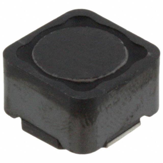
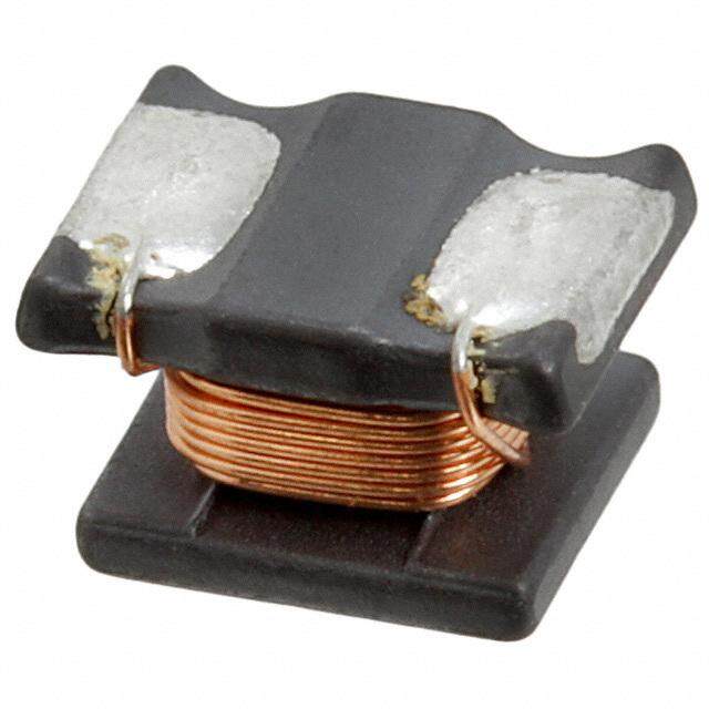
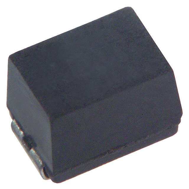
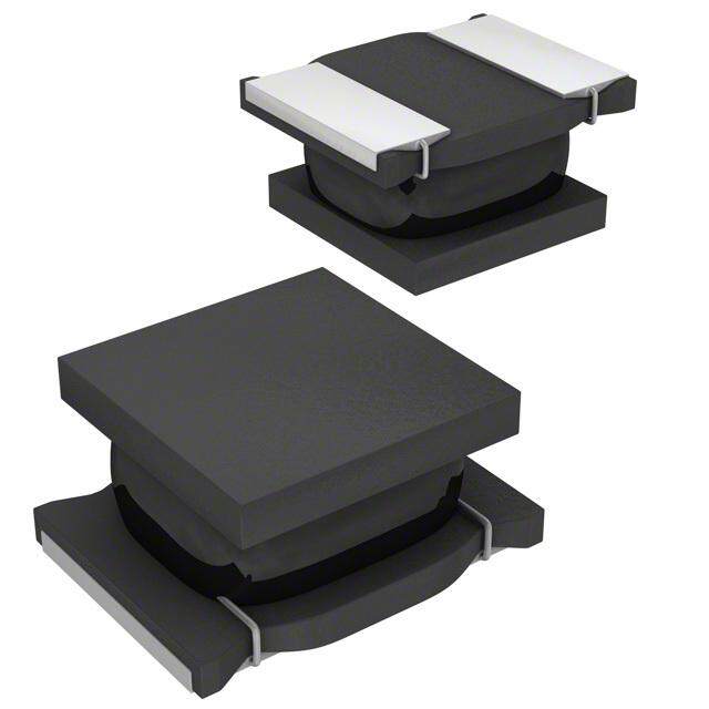
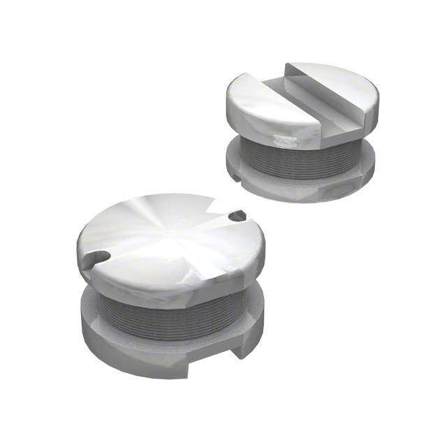
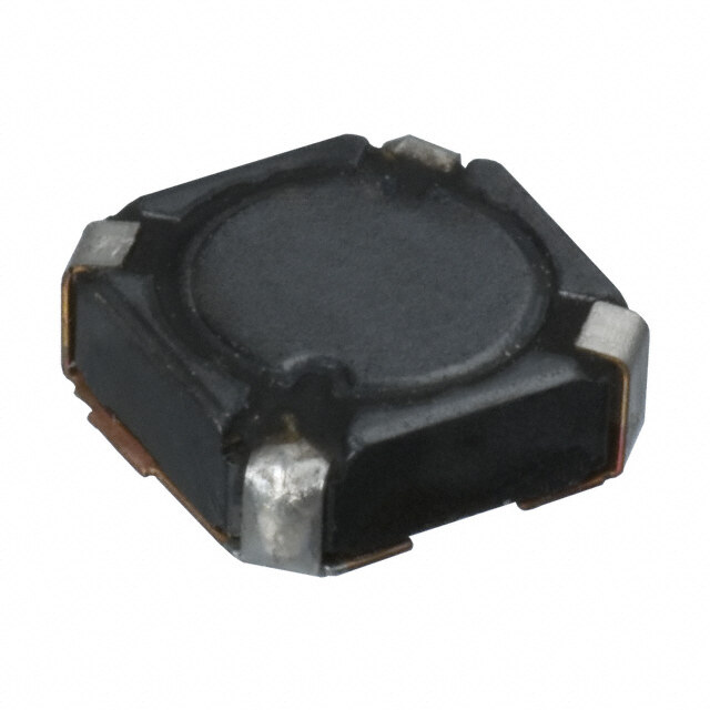
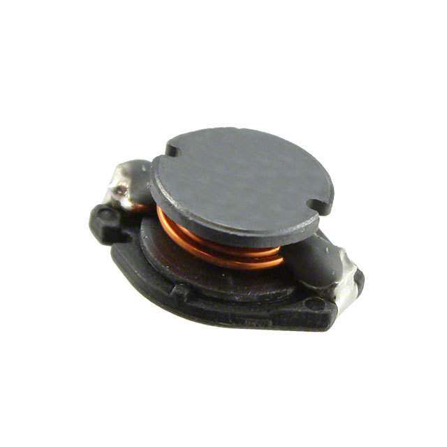
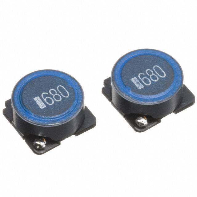
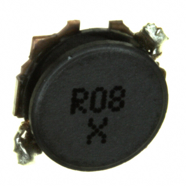
ICGOO电子元器件商城为您提供DRA127-100-R由Bussmann/Cooper设计生产,在icgoo商城现货销售,并且可以通过原厂、代理商等渠道进行代购。 DRA127-100-R价格参考。Bussmann/CooperDRA127-100-R封装/规格:固定值电感器, 10µH Shielded Wirewound Inductor 6.02A 17 mOhm Nonstandard。您可以下载DRA127-100-R参考资料、Datasheet数据手册功能说明书,资料中有DRA127-100-R 详细功能的应用电路图电压和使用方法及教程。
Eaton - Electronics Division旗下的DRA127-100-R是一款固定值电感器,广泛应用于工业控制、电源管理和自动化系统中。该型号具备良好的稳定性和耐用性,适用于需要可靠电感元件的各类电子设备。

其主要应用场景包括:

1. 工业自动化设备:用于PLC(可编程逻辑控制器)、继电器模块和传感器电路中,作为滤波或储能元件,提升系统稳定性。
2. 电源供应器:在开关电源、DC/DC转换器中用作滤波电感,抑制电流波动,提高电源效率与可靠性。
3. 电机驱动与控制系统:用于变频器或伺服驱动器中,帮助平滑输出电流,减少电磁干扰(EMI)。
4. 测试与测量仪器:作为精密电路中的标准电感元件,用于校准和信号处理。
5. 通信设备:在基站电源、路由器等通信基础设施中,提供稳定的电感支持,保障数据传输质量。

DRA127-100-R具有较高的耐压和温升能力,适合在较复杂工作环境中使用,是工业级电子产品中的常用元器件。
| 参数 | 数值 |
| 产品目录 | |
| DC电阻(DCR) | 17 毫欧 |
| 描述 | FIXED IND 10UH 6.02A 17 MOHM SMD固定电感器 10uH 11.2A 0.017ohms |
| 产品分类 | |
| 品牌 | Eaton Bussmann |
| 产品手册 | |
| 产品图片 |
|
| rohs | 符合RoHS无铅 / 符合限制有害物质指令(RoHS)规范要求 |
| 产品系列 | 固定电感器,Coiltronics / Eaton DRA127-100-R自动, AEC-Q200, DRA |
| 数据手册 | |
| 产品型号 | DRA127-100-R |
| 不同频率时的Q值 | - |
| 产品 | Inductors |
| 产品培训模块 | http://www.digikey.cn/PTM/IndividualPTM.page?site=cn&lang=zhs&ptm=26315 |
| 产品种类 | 固定电感器 |
| 供应商器件封装 | - |
| 其它名称 | 283-3584-6 |
| 包装 | Digi-Reel® |
| 单位重量 | 453.592 mg |
| 商标 | Coiltronics / Eaton |
| 外壳宽度 | 12.5 mm |
| 外壳长度 | 12.5 mm |
| 外壳高度 | 8 mm |
| 大小/尺寸 | 0.492" 长 x 0.492" 宽(12.50mm x 12.50mm) |
| 安装类型 | 表面贴装 |
| 容差 | ±20% |
| 封装 | Reel |
| 封装/外壳 | 非标准 |
| 屏蔽 | 屏蔽 |
| 工作温度 | -40°C ~ 165°C |
| 工作温度范围 | - 40 C to + 165 C |
| 工厂包装数量 | 350 |
| 最大直流电流 | 6.02 A |
| 最大直流电阻 | 17 mOhms |
| 材料-磁芯 | - |
| 标准包装 | 1 |
| 测试频率 | 100 kHz |
| 电感 | 10µH |
| 电流-饱和值 | 11.2A |
| 端接类型 | SMD/SMT |
| 类型 | 绕线 |
| 系列 | DRA127 |
| 频率-测试 | 100kHz |
| 频率-自谐振 | - |
| 额定电流 | 6.02A |
| 高度-安装(最大值) | 0.315"(8.00mm) |


- 商务部:美国ITC正式对集成电路等产品启动337调查
- 曝三星4nm工艺存在良率问题 高通将骁龙8 Gen1或转产台积电
- 太阳诱电将投资9.5亿元在常州建新厂生产MLCC 预计2023年完工
- 英特尔发布欧洲新工厂建设计划 深化IDM 2.0 战略
- 台积电先进制程称霸业界 有大客户加持明年业绩稳了
- 达到5530亿美元!SIA预计今年全球半导体销售额将创下新高
- 英特尔拟将自动驾驶子公司Mobileye上市 估值或超500亿美元
- 三星加码芯片和SET,合并消费电子和移动部门,撤换高东真等 CEO
- 三星电子宣布重大人事变动 还合并消费电子和移动部门
- 海关总署:前11个月进口集成电路产品价值2.52万亿元 增长14.8%

PDF Datasheet 数据手册内容提取
DRA Series Magnetics Solutions High Power Density, For Automotive Applications High Efficiency,Shielded Inductors Description RoHS •165°C maximum total temperature operation 2002/95/EC •Five sizes of Automotive grade shielded drum core inductors •Inductance range from 0.28uH to 1000uH •Current range up to 56 Amps •Mechanical secure mounting for high shock and vibration environments •Good thermal dispersion with thermal conductive epoxy •Customized dual winding versions available upon request for SEPIC or Flyback configurations Applications •Automotive Electronics (under the hood, interior/exterior) •Telematics •DC-DC converters Packaging •Buck, boost, forward, and resonant converters •Supplied in tape and reel packaging, 1350 (DRA73), •Noise filtering and filter chokes 1100 (DRA74), 750 (DRA124), 600 (DRA125), Environmental Data and 350 (DRA127) per reel •Storage temperature range:-40°C to +165°C •Operating temperature range:-40°C to +165°C (range is application specific) •Solder reflowtemperature:+260°Cmax.for 10 seconds max. •Complies with AEC-Q200 standard PartNumber Rated OCL (1) Irms (2) Isat (3) Isat (4) DCR (5) K-factor (6) Inductance µH Amperes Amperes Amperes (Ω) +/-20% Typ. DRA73-R33-R 0.33 0.29 8.42 14.80 11.84 0.0040 60.6 DRA73-1R0-R 1.00 0.91 6.50 8.22 6.58 0.0067 33.7 DRA73-1R5-R 1.50 1.36 5.39 6.73 5.38 0.0097 27.5 DRA73-2R2-R 2.20 2.52 4.18 4.93 3.95 0.016 20.2 DRA73-3R3-R 3.30 3.18 3.59 4.35 3.48 0.022 17.8 DRA73-4R7-R 4.70 4.86 2.92 3.52 2.82 0.033 14.4 DRA73-6R8-R 6.80 6.63 2.62 2.96 2.37 0.041 12.1 DRA73-8R2-R 8.20 8.06 2.30 2.74 2.19 0.053 11.2 DRA73-100-R 10.0 10.27 2.11 2.39 1.91 0.064 9.8 DRA73-150-R 15.0 14.98 1.74 2.00 1.60 0.094 8.2 DRA73-220-R 22.0 22.39 1.42 1.64 1.32 0.141 6.7 DRA73-330-R 33.0 31.84 1.25 1.35 1.08 0.183 5.5 DRA73-470-R 47.0 47.83 1.02 1.10 0.884 0.275 4.5 DRA73-680-R 68.0 66.89 0.845 0.937 0.749 0.397 3.8 DRA73-820-R 82.0 83.77 0.731 0.851 0.680 0.530 3.5 DRA73-101-R 100 101.7 0.682 0.763 0.610 0.609 3.1 DRA73-151-R 150 151.1 0.551 0.632 0.506 0.932 2.6 DRA73-221-R 220 218.8 0.479 0.510 0.408 1.23 2.1 DRA73-331-R 330 326.4 0.391 0.423 0.338 1.85 1.7 DRA73-471-R 470 472.6 0.326 0.354 0.283 2.67 1.4 DRA73-681-R 680 682.9 0.270 0.297 0.238 3.89 1.2 DRA73-821-R 820 825.3 0.252 0.267 0.214 4.46 1.1 DRA73-102-R 1000 991.9 0.235 0.239 0.192 5.15 1.0 (1) Open Circuit Inductance test parameters:100kHz, 0.25V,0.0Adc, (5) DCR limits @ 25°C tolerance is ±20% (6) K-factor:Used to determine B p-p for core loss (see graph). (2) Irms:DC current for an approximate ∆Tof 40°C without core loss.Derating is Bp-p = K*L*∆I, B p-p(mT), K:(K factor from table), L:(Inductance in µH), necessaryfor ACcurrents.PCB layout, trace thickness and width, air-flow, and ∆I(Peak to peak ripple current in Amps). proximity of other heat generating components will affect the temperature rise.It (7) PartNumber Definition:DRAxxx-xxx-R is recommended that the temperature of the part not exceed 165°C under worst DRAxxx = Product code and size;-xxx = Inductance value in uH; case operating conditions verified in the end application. R=decimal point;If no R is present, third character = # of zeros. (3) Isat Amperes peak for approximately 30% rolloff (@25°C) -R suffix = RoHS compliant (4) Isat Amperes peak for approximately 40% rolloff (@125°C)
DRA Series Magnetics Solutions High Power Density, For Automotive Applications High Efficiency,Shielded Inductors Part Number Rated OCL (1) Irms (2) Isat (3) Isat (4) DCR (5) K-factor (6) Inductance µH Amperes Amperes Amperes (Ω) +/-20% Typ. DRA74-R33-R 0.33 0.288 7.26 18.40 14.72 0.0054 52.6 DRA74-1R0-R 1.00 0.897 6.01 10.22 8.18 0.0078 29.2 DRA74-1R5-R 1.50 1.31 5.55 8.36 6.69 0.0092 23.9 DRA74-2R2-R 2.20 2.33 4.82 6.13 4.91 0.012 17.5 DRA74-3R3-R 3.30 3.05 4.16 5.41 4.33 0.016 15.5 DRA74-4R7-R 4.70 4.68 3.41 4.38 3.50 0.024 12.5 DRA74-6R8-R 6.80 6.51 2.91 3.68 2.94 0.034 10.5 DRA74-8R2-R 8.20 8.51 2.66 3.17 2.54 0.040 9.1 DRA74-100-R 10.0 9.62 2.56 2.97 2.37 0.043 8.5 DRA74-150-R 15.0 15.14 2.06 2.36 1.89 0.067 6.7 DRA74-220-R 22.0 22.25 1.68 1.96 1.57 0.100 5.6 DRA74-330-R 33.0 33.21 1.37 1.61 1.29 0.151 4.6 DRA74-470-R 47.0 46.56 1.14 1.37 1.099 0.219 3.9 DRA74-680-R 68.0 68.37 0.996 1.108 0.887 0.286 3.2 DRA74-820-R 82.0 81.45 0.879 1.034 0.827 0.367 3.0 DRA74-101-R 100 98.5 0.822 0.929 0.743 0.419 2.7 DRA74-151-R 150 150.9 0.661 0.748 0.598 0.648 2.1 DRA74-221-R 220 218.9 0.544 0.626 0.501 0.96 1.8 DRA74-331-R 330 328.9 0.435 0.514 0.411 1.50 1.5 DRA74-471-R 470 471.5 0.383 0.420 0.336 1.93 1.2 DRA74-681-R 680 682.8 0.315 0.352 0.282 2.86 1.0 DRA74-821-R 820 815.0 0.279 0.327 0.262 3.63 0.9 DRA74-102-R 1000 1001.7 0.260 0.292 0.234 4.19 0.8 DRA124-R47-R 0.47 0.423 15.15 30.80 24.6 0.0019 16.7 DRA124-1R0-R 1.00 0.821 11.65 22.00 17.6 0.0031 12.0 DRA124-1R5-R 1.50 1.36 9.36 17.11 13.7 0.0049 9.3 DRA124-2R2-R 2.20 2.04 7.64 14.00 11.2 0.007 7.6 DRA124-3R3-R 3.30 2.79 6.94 11.85 9.48 0.009 6.4 DRA124-4R7-R 4.70 4.74 5.47 9.06 7.25 0.014 4.9 DRA124-6R8-R 6.80 7.28 4.46 7.33 5.87 0.021 4.0 DRA124-8R2-R 8.20 8.88 3.87 6.70 5.36 0.028 3.6 DRA124-100-R 10.0 10.37 3.67 6.16 4.93 0.031 3.3 DRA124-150-R 15.0 14.10 3.10 5.31 4.25 0.044 2.9 DRA124-220-R 22.0 23.00 2.44 4.16 3.33 0.071 2.3 DRA124-330-R 33.0 34.13 1.98 3.42 2.74 0.108 1.9 DRA124-470-R 47.0 46.27 1.78 2.91 2.325 0.134 1.6 DRA124-680-R 68.0 69.77 1.454 2.369 1.895 0.201 1.3 DRA124-820-R 82.0 80.57 1.285 2.232 1.786 0.257 1.2 DRA124-101-R 100 98.8 1.199 2.000 1.600 0.296 1.1 DRA124-151-R 150 151.7 0.967 1.621 1.297 0.454 0.9 DRA124-221-R 220 209.6 0.865 1.363 1.090 0.568 0.7 DRA124-331-R 330 326.9 0.690 1.092 0.874 0.892 0.6 DRA124-471-R 470 473.0 0.568 0.911 0.729 1.32 0.5 DRA124-681-R 680 682.1 0.466 0.759 0.607 1.96 0.4 DRA124-821-R 820 826.7 0.406 0.697 0.557 2.57 0.4 DRA124-102-R 1000 1001.0 0.380 0.629 0.503 2.94 0.3 DRA125-R47-R 0.47 0.453 18.47 33.20 26.56 0.0016 16.7 DRA125-1R0-R 1.00 0.854 15.94 23.71 18.97 0.0021 12.0 DRA125-1R5-R 1.50 1.41 12.89 18.44 14.76 0.0033 9.3 DRA125-2R2-R 2.20 2.12 10.61 15.09 12.07 0.0048 7.6 DRA125-3R3-R 3.30 2.89 9.69 12.77 10.22 0.0058 6.4 DRA125-4R7-R 4.70 4.90 7.67 9.76 7.81 0.0092 4.9 DRA125-6R8-R 6.80 6.23 6.81 8.74 6.99 0.012 4.4 DRA125-8R2-R 8.20 7.49 6.41 7.90 6.32 0.013 4.0 DRA125-100-R 10.0 9.22 5.57 7.22 5.77 0.017 3.6 (1) Open Circuit Inductance test parameters:100kHz, 0.25V, 0.0Adc, (5) DCR limits @ 25°C tolerance is ±20% (6) K-factor:Used to determine B p-p for core loss (see graph). (2) Irms:DC current for an approximate ∆Tof40°C without core loss.Derating is Bp-p = K*L*∆I, B p-p(mT), K:(K factor from table), L:(Inductance in µH), necessary for AC currents.PCB layout, trace thickness and width, air-flow, and ∆I(Peak to peak ripple current in Amps). proximity of other heat generating components will affect the temperature rise.It (7) Part Number Definition:DRAxxx-xxx-R is recommended that the temperature of the part not exceed 165°C under worst DRAxxx = Product code and size;-xxx = Inductance value in uH; case operating conditions verified in the end application. R=decimal point;If no R is present, third character = # of zeros. (3) Isat Amperes peak for approximately 30% rolloff (@25°C) -R suffix = RoHS compliant (4) Isat Amperes peak for approximately 40% rolloff (@125°C)
DRA Series Magnetics Solutions High Power Density, For Automotive Applications High Efficiency,Shielded Inductors Part Number Rated OCL (1) Irms (2) Isat (3) Isat (4) DCR (5) K-factor (6) Inductance µH Amperes Amperes Amperes (Ω) +/-20% Typ. DRA125-150-R 15.0 14.67 4.45 5.72 4.58 0.027 2.9 DRA125-220-R 22.0 20.65 3.95 4.74 3.79 0.035 2.4 DRA125-330-R 33.0 31.47 3.19 3.86 3.09 0.053 1.9 DRA125-470-R 47.0 47.83 2.59 3.13 2.506 0.081 1.6 DRA125-680-R 68.0 68.48 2.125 2.635 2.108 0.120 1.3 DRA125-820-R 82.0 80.86 2.005 2.406 1.925 0.135 1.2 DRA125-101-R 100 97.6 1.745 2.213 1.771 0.178 1.1 DRA125-151-R 150 150.0 1.409 1.785 1.428 0.273 0.9 DRA125-221-R 220 222.8 1.142 1.469 1.175 0.416 0.7 DRA125-331-R 330 325.1 0.998 1.194 0.955 0.543 0.6 DRA125-471-R 470 466.3 0.826 1.006 0.805 0.79 0.5 DRA125-681-R 680 683.3 0.673 0.834 0.667 1.20 0.4 DRA125-821-R 820 813.6 0.632 0.758 0.606 1.36 0.4 DRA125-102-R 1000 992.8 0.552 0.695 0.556 1.78 0.4 DRA127-R47-R 0.47 0.413 22.50 56.0 44.8 0.0012 14.3 DRA127-1R0-R 1.00 0.772 19.22 40.0 32.0 0.0017 10.2 DRA127-1R5-R 1.50 1.27 15.32 31.1 24.9 0.0027 7.9 DRA127-2R2-R 2.20 1.92 12.52 25.5 20.4 0.0040 6.5 DRA127-3R3-R 3.30 3.51 9.59 18.7 14.93 0.0068 4.8 DRA127-4R7-R 4.70 4.58 8.14 16.5 13.18 0.0094 4.2 DRA127-6R8-R 6.80 6.72 7.32 13.3 10.67 0.012 3.4 DRA127-8R2-R 8.20 8.33 6.33 12.2 9.74 0.016 3.1 DRA127-100-R 10.0 9.63 6.02 11.2 8.96 0.017 2.9 DRA127-150-R 15.0 14.90 4.83 9.03 7.23 0.027 2.3 DRA127-220-R 22.0 21.47 3.98 7.57 6.05 0.040 1.9 DRA127-330-R 33.0 32.01 3.22 6.22 4.98 0.060 1.6 DRA127-470-R 47.0 47.91 2.62 5.09 4.07 0.091 1.3 DRA127-680-R 68.0 68.22 2.333 4.18 3.34 0.115 1.1 DRA127-820-R 82.0 83.91 2.008 3.84 3.07 0.155 1.0 DRA127-101-R 100 100.8 1.888 3.46 2.77 0.175 0.9 DRA127-151-R 150 151.2 1.524 2.83 2.26 0.269 0.7 DRA127-221-R 220 219.8 1.253 2.35 1.88 0.398 0.6 DRA127-331-R 330 328.3 1.011 1.93 1.54 0.612 0.5 DRA127-471-R 470 474.5 0.827 1.62 1.29 0.91 0.4 DRA127-681-R 680 676.6 0.736 1.33 1.06 1.15 0.3 DRA127-821-R 820 824.6 0.637 1.22 0.978 1.54 0.3 DRA127-102-R 1000 998.7 0.598 1.10 0.878 1.75 0.3 (1) Open Circuit Inductance test parameters:100kHz, 0.25V,0.0Adc, (5) DCR limits @ 25°C tolerance is ±20% (6) K-factor:Used to determine B p-p for core loss (see graph). (2) Irms:DC current for an approximate ∆Tof 40°C without core loss.Derating is Bp-p = K*L*∆I, B p-p(mT), K:(K factor from table), L:(Inductance in µH), necessaryfor ACcurrents.PCB layout, trace thickness and width, air-flow, and ∆I(Peak to peak ripple current in Amps). proximity of other heat generating components will affect the temperature rise.It (7) Part Number Definition:DRAxxx-xxx-R is recommended that the temperature of the partnotexceed 165°C under worst DRAxxx = Product code and size;-xxx = Inductance value in uH; case operating conditions verified in the end application. R=decimal point;If no R is present, third character = # of zeros. (3) Isat Amperes peak for approximately 30% rolloff (@25°C) -R suffix = RoHS compliant (4) Isat Amperes peak for approximately 40% rolloff (@125°C) Mechanical Diagrams DRA73 Series BOTTOM VIEW FRONT VIEW TOP VIEW RECOMMENDED PCBLAYOUT SCHEMATIC 1 7.6Max 2.50 7.6Max 2 ww#ll#y#y R 1 3.25 2.00 2 3.55 8.50 1.5 Max Dimensions in Millimeters. ### = Inductance value in uH.R = decimal point. Ifno R is present third character = # of zeros wwllyy = (date code) R = revision level
DRA Series Magnetics Solutions High Power Density, For Automotive Applications High Efficiency,Shielded Inductors Mechanical Diagrams DRA74 Series BOTTOM VIEW FRONT VIEW TOP VIEW RECOMMENDED PCBLAYOUT SCHEMATIC 7.6 Max 2.50 1 ### 7.6 Max 2 wwllyy R 1 3.25 2.00 2 4.35 Max 8.50 1.5 DRA124 Series BOTTOM VIEW FRONT VIEW TOP VIEW RECOMMENDED PCB LAYOUT 3.85 1 DRA124 5.00 1M2.a5x0 2 ### 1 wwllyy R 5.5 12.50 4.5 2 Max Max 13.8 2.50 DRA125 Series BOTTOM VIEW FRONTVIEW TOP VIEW RECOMMENDEDPCB LAYOUT SCHEMATIC 3.85 1 DRA125 5.00 1M2a.5x0 2 ### 1 wwllyy R 5.5 2 12.50 6.0 Max Max 2.50 13.8 DRA127 Series BOTTOM VIEW FRONT VIEW TOP VIEW RECOMMENDED PCB LAYOUT SCHEMATIC 3.85 1 12.50 DRA127 5.00 Max 2 ### 1 wwllyy R 5.5 12.50 8.0 2 Max Max 2.50 13.8 Dimensions in Millimeters. ###=Inductance value in uH.R = decimal point. If no R is present third character = # of zeros wwllyy = (date code) R = revision level
DRA Series Magnetics Solutions High Power Density, For Automotive Applications High Efficiency,Shielded Inductors Packaging Information DRA73 Series Ø1.50 +0.1/-0.0 2.00 ±0.1 Ø1.50 Min. 4.00 A 1.75±0.10 7.50±01. 16.00 Bo DRA73### ±0.3 A0= 7.90mm B0=7.90mm Ko A K0= 3.80mm Ao SECTION A-A 12.00 Parts packaged on 13" Diameter reel, User direction of feed 1,350 parts per reel. DRA74 Series Ø1.50 +0.1/-0.0 2.00 ±0.1 Ø1.50 Min. 4.00 A 1.75±0.10 7.50±0.1 16.00 Bo 4DR7A### ±0.3 A0= 7.90 mm B0= 7.90 mm Ko A K0= 4.70 mm Ao User direction of feed Parts packaged on 13" Diameter reel, SECTION A-A 12.00 1,100 parts per reel. DRA124 Series 1.5 dia +0.1/-0.0 2.0 1.5 dia min A 1.75 11.5 B0 R24-##DA1#wwllyyR +2/-40..03 A0= 13.00 mm B0= 13.00mm K0= 4.90 mm K0 A0 16.00 A SECTION A-A Parts packaged on 13" Diameter reel, User direction of feed 750 parts per reel. DRA125 Series 1.5 dia +0.1/-0.0 2.0 1.5 dia min A 1.75 A0= 13.00 mm B0 DRA125-###wwllyyR 11.5 +2/-40.0.3 B0= 13.00 mm K0= 6.30 mm K0 A0 16.00 A SECTION A-A Parts packaged on 13" Diameter reel, User direction of feed 600 parts per reel. DRA127 Series 1.5 dia +0.1/-0.0 2.0 1.5 dia min A 1.75 11.5 A0= 13.00mm B0 RDA127-###wwllyyR +2/-40.0.3 B0= 13.00mm K0= 8.30mm K0 A0 20.00 A SECTION A-A User direction of feed Parts packaged on 13" Diameter reel, Dimensions are in millimeters. 350 parts per reel.
DRA Series Magnetics Solutions High Power Density, For Automotive Applications High Efficiency,Shielded Inductors Temperature Rise vs.Watt Loss DRA 73 series DRA 74 series 70 70 60 60 50 50 Rise(°C)40 Rise(°C)40 Temp.30 Temp.30 20 20 10 10 0 0 0 0.04 0.08 0.12 0.16 0.2 0.24 0.28 0.32 0.36 0.4 0.44 0.48 0.52 0.56 0.6 0.64 0.68 0 0.1 0.2 0.3 0.4 0.5 0.6 0.7 0.8 0.9 1 1.1 1.2 To tal L o ss (W ) Total Loss (W) DRA 124 series DRA 125 series 70 70 60 60 50 50 C) C) Rise(°40 Rise(°40 mp.30 mp.30 Te Te 20 20 10 10 0 0 0 0.1 0.2 0.3 0.4 0.5 0.6 0.7 0.8 0.9 1 1.1 1.2 1.3 0 0.1 0.2 0.3 0.4 0.5 0.6 0.7 0.8 0.9 1 1.1 1.2 1.3 To tal Lo ss(W ) Total Loss (W) DRA 127 series 80 70 60 C)50 Rise(°40 p. m Te30 20 10 0 0 0.1 0.2 0.3 0.4 0.5 0.6 0.7 0.8 0.9 1 1.1 1.2 1.3 1.4 1.5 Total Loss (W)
DRA Series Magnetics Solutions High Power Density, For Automotive Applications High Efficiency,Shielded Inductors Inductance Characteristics OCL vs Isat/DRA 74 series OCL vs Isat/DRA 73 series 120% 120% 110% 110% 100% 100% 90% 90% 80% 80% LC 70% -40° CL 70% -40° O of 60% 25° ofO 60% 25° % 50% % 50% 40% 40% 30% 85° 30% 85° 20% 20% 125° 125° 10% 10% 0% 0% 0% 10% 20% 30% 40% 50% 60% 70% 80% 90% 100% 110% 120% 130% 140% 0% 10% 20% 30% 40% 50% 60% 70% 80% 90% 100% 110% 120% %ofIsat %ofIsat OCL vsIsat/DRA 125 series OCL vsIsat/DRA 124 series 120% 120% 110% 110% 100% 100% 90% 90% 80% 80% OCL 70% -40° OCL 70% -40° of 60% of 60% % 50% % 50% 25° 25° 40% 40% 30% 85° 30% 85° 125° 20% 20% 125° 10% 10% 0% 0% 0% 10% 20% 30% 40% 50% 60% 70% 80% 90% 100%110%120%130%140%150%160% 0% 10% 20% 30% 40% 50% 60% 70% 80% 90% 100% 110% 120% 130% 140% %ofIsat %ofIsat OCL vsIsat/DRA 127 series 120% 110% 100% 90% -40° 80% 25° CL 70% O of 60% 85° % 50% 40% 125° 30% 20% 10% 0% 60% 70% 80% 90% 100% 110% 120% 130% 140% 150% 160% 170% 180% 190% 200% %ofIsat
DRA Series Magnetics Solutions High Power Density, For Automotive Applications High Efficiency,Shielded Inductors Inductance Characteristics DRA 73 series DRA 74 series 100 100 1MHz 1MHz 10 500kHz 10 500kHz 300kHz 300kHz 1 200kHz 200kHz CoreLoss(W) 0.00.11 15000kkHHzz ossCreo(W)L 0.11 15000kkHHzz 0.01 0.001 0.0001 0.001 0.00001 0.0001 1 10 100 100 1 10 100 1000 Bp-p (mT) Bp-p (mT) DRA 124 series DRA 125 series 1000 1000 1MHz 1MHz 100 500kHz 100 500kHz 300kHz 300kHz 10 200kHz 10 200kHz 100kHz 100kHz CoreLoss(W) 0.11 50kHz CoreLoss(W) 0.11 50kHz 0.01 0.01 0.001 0.001 0.0001 0.0001 1 10 100 1000 1 10 100 1000 Bp-p (mT) Bp-p (mT) DRA 127 series 1000 1MHz 100 500kHz 300kHz 10 200kHz W) 100kHz Loss( 1 50kHz roe C 0.1 0.01 0.001 1 10 100 1000 Bp-p (mT) PM-4319 3/07 Visit us on the Web at www.cooperbussmann.com ©Cooper Electronic 1225 Broken Sound Pkwy.Suite F Boca Raton, FL 33487 Technologies 2007 Tel:+1-561-998-4100 Toll Free:+1-888-414-2645 Fax:+1-561-241-6640 This bulletin is intended to present product design solutions and technical information that will help the end user with design applications. Cooper Electronic Technologies reserves the right, without notice, to change design or construction of any products and to discontinue or limit distribution of any products. Cooper Electronic Technologies also reserves the right to change or update, without notice, any technical information contained in this bulletin. Once a product has been selected, it should be tested by the user in all possible applications. Life Support Policy: Cooper Electronic Technologies does not authorize the use of any of its products for use in life support devices or systems without the express written approval of an officer of the Company.Life support systems are devices which support or sustain life, and whose failure to perform, when properly used in accordance with instructions for use provided in the labeling, can be reasonably expected to result in significant injuryto the user.