ICGOO在线商城 > 电感器,线圈,扼流圈 > 固定值电感器 > DR125-220-R
 Datasheet下载
- 型号: DR125-220-R
- 制造商: Bussmann/Cooper
- 库位|库存: xxxx|xxxx
- 要求:
| 数量阶梯 | 香港交货 | 国内含税 |
| +xxxx | $xxxx | ¥xxxx |
查看当月历史价格
查看今年历史价格
DR125-220-R产品简介:
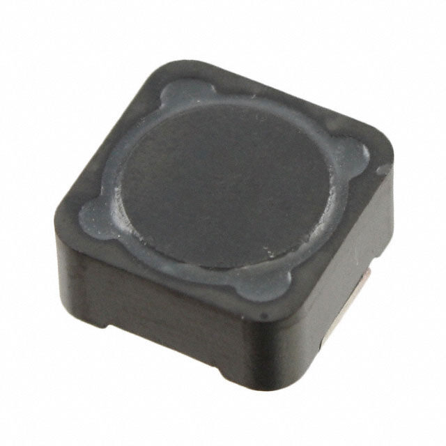
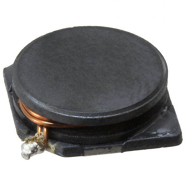
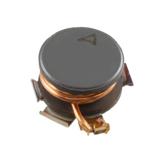
ICGOO电子元器件商城为您提供DR125-220-R由Bussmann/Cooper设计生产,在icgoo商城现货销售,并且可以通过原厂、代理商等渠道进行代购。 DR125-220-R价格参考。Bussmann/CooperDR125-220-R封装/规格:固定值电感器, 22µH Shielded Wirewound Inductor 3.7A 39.6mOhm Nonstandard 。您可以下载DR125-220-R参考资料、Datasheet数据手册功能说明书,资料中有DR125-220-R 详细功能的应用电路图电压和使用方法及教程。
Eaton - Electronics Division 的 DR125-220-R 是一款固定值电感器,属于DR125系列,典型电感值为22μH,具有高饱和电流和低直流电阻的特性。该电感器主要应用于工业和电力电子领域,常见使用场景包括:

1. 电源转换系统:广泛用于开关模式电源(SMPS)、DC-DC转换器中,作为滤波或储能元件,有效抑制电流波动,提高电源稳定性。

2. 工业电机驱动:在变频器和电机控制装置中,用于平滑输出电流、减少电磁干扰(EMI),提升系统运行效率与可靠性。

3. 可再生能源系统:适用于太阳能逆变器和风能转换系统,帮助优化能量传输,增强系统抗干扰能力。

4. UPS不间断电源:在备用电源设备中发挥滤波作用,确保输出电压平稳,保护敏感电子设备。

5. 工业自动化设备:用于PLC(可编程逻辑控制器)、工控电源模块等,提供可靠的电磁兼容性支持。

DR125-220-R采用耐高温材料和坚固结构设计,可在恶劣工业环境下稳定工作,具备良好的散热性能和长期可靠性,适合高负载、连续运行的应用场合。其紧凑尺寸也便于集成于空间受限的电路板设计中。
| 参数 | 数值 |
| 产品目录 | |
| DC电阻(DCR) | 39.6 毫欧 |
| 描述 | INDUCTOR SHIELD PWR 22UH SMD固定电感器 22uH 4.7A 0.0396ohms |
| 产品分类 | |
| 品牌 | Eaton Bussmann |
| 产品手册 | |
| 产品图片 |
|
| rohs | 符合RoHS无铅 / 符合限制有害物质指令(RoHS)规范要求 |
| 产品系列 | 固定电感器,Bussmann / Eaton DR125-220-RDR |
| 数据手册 | |
| 产品型号 | DR125-220-R |
| 不同频率时的Q值 | - |
| 产品 | Inductors |
| 产品培训模块 | http://www.digikey.cn/PTM/IndividualPTM.page?site=cn&lang=zhs&ptm=26315 |
| 产品目录绘图 |
|
| 产品目录页面 | |
| 产品种类 | 固定电感器 |
| 供应商器件封装 | - |
| 其它名称 | 513-1127-2 |
| 包装 | 带卷 (TR) |
| 单位重量 | 4.082 g |
| 商标 | Bussmann / Eaton |
| 外壳宽度 | 12.5 mm |
| 外壳长度 | 12.5 mm |
| 外壳高度 | 6 mm |
| 大小/尺寸 | 0.492" 长 x 0.492" 宽(12.50mm x 12.50mm) |
| 安装类型 | 表面贴装 |
| 容差 | ±20% |
| 封装 | Bulk |
| 封装/外壳 | 非标准 |
| 屏蔽 | 屏蔽 |
| 工作温度 | -40°C ~ 125°C |
| 工作温度范围 | - 40 C to + 125 C |
| 工厂包装数量 | 600 |
| 最大直流电流 | 4.71 A |
| 最大直流电阻 | 39.6 mOhms |
| 材料-磁芯 | 铁氧体 |
| 标准包装 | 600 |
| 测试频率 | 100 kHz |
| 电感 | 22µH |
| 电流-饱和值 | 4.71A |
| 端接类型 | SMD/SMT |
| 类型 | 绕线 |
| 系列 | DR |
| 芯体材料 | Ferrite |
| 频率-测试 | 100kHz |
| 频率-自谐振 | - |
| 额定电流 | 3.7A |
| 高度-安装(最大值) | 0.236"(6.00mm) |


PDF Datasheet 数据手册内容提取
Effective September 2017 Technical Data 4315 Supersedes April 2014 DR High power density, high efficiency, shielded drum core power inductors Applications • Desktop and servers • DVD and media players • Portable and handheld devices • LCD panels • DC-DC converters • Buck, boost, forward, and resonant converters • Noise filtering and filter chokes Environmental data • Storage temperature range (component): Product features -40 °C to +125 °C • Operating temperature range: -40 °C to +125 °C • Four sizes of shielded drum core inductors (ambient plus self-temperature rise) • Inductance range from 0.33 µH to 1000 µH • Solder reflow temperature: • Current range up to 56 A peak J-STD-020 (latest revision) compliant • Magnetically shielded •• SFeercruitree cmoroeu mntaintgerial Pb HHALOFGEN FREE
Technical Data 4315 DR Effective September 2017 High power density, high efficiency, shielded drum core power inductors Product specifications Rated OCL1 I 3 DCR4 sat Inductance ±20% I 2 (A) (Ω) Volt-μsec5 rms Part Number (μH) (μH) (A) Peak Typ. Typ. DR73-R33-R 0.33 0.306 6.21 14.4 0.0073 1.98 DR73-1R0-R 1.00 0.992 5.28 7.97 0.0102 3.56 DR73-1R5-R 1.50 1.482 4.67 6.52 0.0130 4.36 DR73-2R2-R 2.20 2.070 4.15 5.52 0.0165 5.15 DR73-3R3-R 3.30 3.540 3.31 4.22 0.0259 6.73 DR73-4R7-R 4.70 4.422 3.09 3.78 0.0297 7.52 DR73-6R8-R 6.80 6.480 2.55 3.12 0.0435 9.11 DR73-8R2-R 8.20 8.930 2.19 2.66 0.0592 10.7 DR73-100-R 10.0 10.30 2.08 2.47 0.0656 11.5 DR73-150-R 15.0 15.01 1.83 2.05 0.0844 13.9 DR73-220-R 22.0 22.65 1.62 1.67 0.107 17.0 DR73-330-R 33.0 34.41 1.31 1.35 0.166 21.0 DR73-470-R 47.0 48.62 1.08 1.14 0.241 24.9 DR73-680-R 68.0 68.91 0.89 0.96 0.358 29.7 DR73-820-R 82.0 80.37 0.86 0.89 0.384 32.1 DR73-101-R 100 101.4 0.73 0.79 0.527 36.0 DR73-151-R 150 150.9 0.58 0.65 0.851 44.0 DR73-221-R 220 223.3 0.52 0.53 1.05 53.5 DR73-331-R 330 325.5 0.42 0.44 1.59 64.5 DR73-471-R 470 465.8 0.35 0.37 2.36 77.2 DR73-681-R 680 676.5 0.29 0.31 3.47 93.1 DR73-821-R 820 821.7 0.27 0.28 3.93 103 DR73-102-R 1000 995.0 0.26 0.25 4.34 113 1. Open Circuit Inductance Test Parameters: 100 kHz, 0.25 V , 0.0 Adc. 6. Part number definition: DRxxx-yyy-R rms 2. RMS current for an approximate DT of 40 °C without core loss. - DRxxx = product code and size, It is recommended that the temperature of the part not exceed +125 °C. - yyy = inductance value in μH, 3. Peak current for approximate 30% roll off at +20 °C. - R = decimal point. If no R is present, third character = # of zeros 4. DCR limits @ +20 °C. - “-R” suffix = RoHS compliant 5. Applied Volt-Time product (V-μs) across the inductor. This value represent the applied V-μsec 100 kHz necessary to generate a core loss equal to 10% of the total losses for 40 °C temperature rise. 2 www.eaton.com/electronics
DR Technical Data 4315 High power density, high efficiency, shielded drum core power inductors Effective September 2017 Product specifications Rated OCL1 I 3 DCR4 sat Inductance ±20% I 2 (A) (Ω) Volt-μsec5 rms Part Number (μH) (μH) (A) Peak Typ. Typ. DR74-R33-R 0.33 0.294 6.26 18.4 0.0074 1.71 DR74-1R0-R 1.00 0.952 5.39 10.2 0.0099 3.08 DR74-1R5-R 1.50 1.422 4.94 8.35 0.0118 3.76 DR74-2R2-R 2.20 1.986 4.76 7.06 0.0126 4.45 DR74-3R3-R 3.30 3.396 3.94 5.40 0.0183 5.81 DR74-4R7-R 4.70 5.182 3.34 4.37 0.0254 7.18 DR74-6R8-R 6.80 7.344 2.60 3.67 0.0418 8.55 DR74-8R2-R 8.20 8.566 2.53 3.40 0.0441 9.23 DR74-100-R 10.0 9.882 2.41 3.17 0.0489 9.92 DR74-150-R 15.0 16.09 2.11 2.48 0.0637 12.7 DR74-220-R 22.0 21.73 1.75 2.13 0.0925 14.7 DR74-330-R 33.0 33.01 1.41 1.73 0.143 18.1 DR74-470-R 47.0 49.64 1.15 1.41 0.216 22.2 DR74-680-R 68.0 69.67 1.03 1.19 0.265 26.3 DR74-820-R 82.0 80.95 0.91 1.11 0.345 28.4 DR74-101-R 100 101.6 0.86 0.99 0.383 31.8 DR74-151-R 150 150.0 0.69 0.81 0.591 38.6 DR74-221-R 220 227.0 0.56 0.66 0.907 47.5 DR74-331-R 330 335.6 0.45 0.54 1.41 57.8 DR74-471-R 470 465.3 0.40 0.46 1.74 68.1 DR74-681-R 680 671.2 0.33 0.38 2.58 81.7 DR74-821-R 820 812.7 0.31 0.35 2.93 89.9 DR74-102-R 1000 1009 0.27 0.31 3.89 100 1. Open Circuit Inductance Test Parameters: 100 kHz, 0.25 V , 0.0 Adc. 6. Part number definition: DRxxx-yyy-R rms 2. RMS current for an approximate DT of 40 °C without core loss. - DRxxx = product code and size, It is recommended that the temperature of the part not exceed +125 °C. - yyy = inductance value in μH, 3. Peak current for approximate 30% roll off at +20 °C. - R = decimal point. If no R is present, third character = # of zeros 4. DCR limits @ +20 °C. - “-R” suffix = RoHS compliant 5. Applied Volt-Time product (V-μs) across the inductor. This value represent the applied V-μsec 100 kHz necessary to generate a core loss equal to 10% of the total losses for 40 °C temperature rise. www.eaton.com/electronics 3
Technical Data 4315 DR Effective September 2017 High power density, high efficiency, shielded drum core power inductors Product specifications Rated OCL1 I 3 DCR4 sat Inductance ±20% I 2 (A) (Ω) Volt-μsec5 rms Part Number (μH) (μH) (A) Peak Typ. Typ. DR125-R47-R 0.47 0.456 17.6 33.0 0.0018 3.17 DR125-1R0-R 1.00 0.894 15.0 23.6 0.0024 4.43 DR125-1R5-R 1.50 1.478 13.8 18.3 0.0029 5.70 DR125-2R2-R 2.20 2.208 10.9 15.0 0.0045 6.97 DR125-3R3-R 3.30 3.084 9.26 12.7 0.0063 8.23 DR125-4R7-R 4.70 5.274 7.18 9.71 0.0105 10.8 DR125-6R8-R 6.80 6.588 6.64 8.68 0.0123 12.0 DR125-8R2-R 8.20 8.048 5.54 7.86 0.0176 13.3 DR125-100-R 10.0 9.654 5.35 7.17 0.0189 14.6 DR125-150-R 15.0 15.35 4.27 5.69 0.0298 18.4 DR125-180-R 18.0 17.70 3.81 5.32 0.0377 19.6 DR125-220-R 22.0 22.36 3.70 4.71 0.0396 22.2 DR125-330-R 33.0 33.74 3.28 3.84 0.0505 27.2 DR125-470-R 47.0 47.47 2.71 3.24 0.0740 32.3 DR125-560-R 56.0 55.24 2.31 3.00 0.102 34.8 DR125-680-R 68.0 67.91 2.22 2.70 0.101 38.6 DR125-820-R 82.0 86.89 2.05 2.39 0.128 43.7 DR125-101-R 100 102.7 1.78 2.20 0.170 47.5 DR125-151-R 150 151.1 1.48 1.81 0.248 57.6 DR125-221-R 220 216.8 1.19 1.51 0.384 69.0 DR125-331-R 330 332.6 1.06 1.22 0.482 85.5 DR125-471-R 470 473.1 0.87 1.02 0.718 102 DR125-681-R 680 679.8 0.70 0.85 1.10 122 DR125-821-R 820 828.0 0.60 0.77 1.49 135 DR125-102-R 1000 1008 0.57 0.70 1.69 149 DR125-472-R 4700 4720 0.268 0.32 7.53 322.4 DR125-124-R 120000 120630 0.060 0.069 150 1521 1. Open Circuit Inductance Test Parameters: 100 kHz, 0.25 V , 0.0 Adc. 6. Part number definition: DRxxx-yyy-R rms 2. RMS current for an approximate DT of 40 °C without core loss. - DRxxx = product code and size, It is recommended that the temperature of the part not exceed +125 °C. - yyy = inductance value in μH, 3. Peak current for approximate 30% roll off at +20 °C. - R = decimal point. If no R is present, third character = # of zeros 4. DCR limits @ +20 °C. - “-R” suffix = RoHS compliant 5. Applied Volt-Time product (V-μs) across the inductor. This value represent the applied V-μsec 100 kHz necessary to generate a core loss equal to 10% of the total losses for 40 °C temperature rise. 4 www.eaton.com/electronics
DR Technical Data 4315 High power density, high efficiency, shielded drum core power inductors Effective September 2017 Product specifications Rated OCL1 I 3 DCR4 sat Inductance ±20% I 2 (A) (Ω) Volt-μsec5 rms Part Number (μH) (μH) (A) Peak Typ. Typ. DR127-R47-R 0.47 0.419 17.9 56.0 0.00195 3.50 DR127-1R0-R 1.00 0.821 15.5 40.0 0.00313 4.90 DR127-1R5-R 1.50 1.357 13.5 31.1 0.00341 6.30 DR127-2R2-R 2.20 2.027 12.5 25.5 0.00402 7.70 DR127-3R3-R 3.30 2.831 10.5 21.5 0.00567 9.10 DR127-4R7-R 4.70 4.841 8.25 16.5 0.00917 11.9 DR127-6R8-R 6.80 7.387 7.34 13.3 0.0116 14.7 DR127-8R2-R 8.20 8.861 6.32 12.2 0.0157 16.1 DR127-100-R 10.0 10.47 6.04 11.2 0.0172 17.5 DR127-150-R 15.0 14.09 5.03 9.66 0.0247 20.3 DR127-220-R 22.0 22.93 4.00 7.57 0.0391 25.9 DR127-330-R 33.0 33.92 3.23 6.22 0.0600 31.5 DR127-470-R 47.0 47.05 2.95 5.28 0.0719 37.1 DR127-680-R 68.0 66.48 2.44 4.44 0.105 44.1 DR127-820-R 82.0 79.75 2.09 4.06 0.143 48.3 DR127-101-R 100 99.31 1.96 3.64 0.163 53.9 DR127-151-R 150 144.9 1.59 3.01 0.247 65.1 DR127-221-R 220 221.5 1.29 2.43 0.376 80.5 DR127-331-R 330 323.6 1.04 2.01 0.574 97.3 DR127-471-R 470 467.1 0.85 1.68 0.861 117 DR127-681-R 680 676.7 0.76 1.39 1.08 141 DR127-821-R 820 818.1 0.65 1.27 1.47 155 DR127-102-R 1000 1005 0.61 1.14 1.66 172 1. Open Circuit Inductance Test Parameters: 100 kHz, 0.25 V , 0.0 Adc. 6. Part number definition: DRxxx-yyy-R rms 2. RMS current for an approximate DT of 40 °C without core loss. - DRxxx = product code and size, It is recommended that the temperature of the part not exceed +125 °C. - yyy = inductance value in μH, 3. Peak current for approximate 30% roll off at +20 °C. - R = decimal point. If no R is present, third character = # of zeros 4. DCR limits @ +20 °C. - “-R” suffix = RoHS compliant 5. Applied Volt-Time product (V-μs) across the inductor. This value represent the applied V-μsec 100 kHz necessary to generate a core loss equal to 10% of the total losses for 40 °C temperature rise. www.eaton.com/electronics 5
Technical Data 4315 DR Effective September 2017 High power density, high efficiency, shielded drum core power inductors Dimensions - mm DR73 BOTTOM VIEW FRONT VIEW TOP VIEW RECOMMENDED PAD LAYOUT SCHEMATIC 6.0 2.50 1 7.6 Max 7.6 DR73 2.0 Max 3.55 ### 3.25 Max wllyy R 2 8.50 1.13 DR74 BOTTOM VIEW FRONT VIEW TOP VIEW RECOMMENDED PAD LAYOUT SCHEMATIC M7a.6x 2.50 1 DR74 7.6 2.0 ### Max 4.35 wllyy R 3.25 Max 2 1.13 8.50 DR125 BOTTOM VIEW FRONT VIEW TOP VIEW RECOMMENDED PAD LAYOUT SCHEMATIC 2.05 Typ. 13.80 1 4T.y9p0 2 1 1M2a.5x0 M6.a0x0 1 DwRw1ll2y5y- # #R# 2 5.50 2 12.50 Max 10 3.85 DR127 BOTTOM VIEW FRONT VIEW TOP VIEW RECOMMENDED PAD LAYOUT SCHEMATIC 2.05 Typ. 13.80 4Ty.9p0 2 1 1M2a.5x0 M8.a0x0 12 DR127-### 5.50 1 wwllyy R 12.50 3.85 2 Max 10 ### = Inductance value per family chart wllyy and wwllyy = (date code) R = revision level 6 www.eaton.com/electronics
DR Technical Data 4315 High power density, high efficiency, shielded drum core power inductors Effective September 2017 Packaging information - mm DR73 Supplied in tape and reel packaging, Ø1.50 +0.1/-0.0 1350 parts per reel, 13" diameter reel. 2.00 ±0.1 12.00 Ø1.50 Min. 4.00 A 1.75±0.10 1 7.50±0.1 Bo wllyy R###DR73 ±0.3 ACTUAL SIZE DR73 2 Ao=7.90mm Ko Ao A Bo=7.90mm User direction of feed Ko=3.80mm SECTION A-A DR74 Supplied in tape and reel packaging, 1100 parts per reel, 13" diameter reel. Ø1.50 +0.1/-0.0 12.00 2.00 ±0.1 Ø1.50 Min. 4.00 A 1.75±0.10 1 7.50±0.1 Bo wllyy R###DR74 ±0.3 ACTDURA7L4 SIZE Ao=7.90mm 2 Bo=7.90mm Ko Ao A Ko=4.70mm SECTION A-A User direction of feed DR125 Supplied in tape and reel packaging, 4.0 600 parts per reel,13" diameter reel +0.1/-0.0 2.0 1min A 1.7 1 11.5 wD wR B0 llyy R125-### +/-0.3 ACTUAL SIZE DR125 Ao=13.0mm 2 Bo=13.0mm A0 16.00 A K0 Ko=6.30mm SECTION A-A User direction of feed DR127 Supplied in tape and reel packaging, 4.0 350 parts per reel, 13" diameter reel. +0.1/-0.0 2.0 min A 1.7 1 11.5 wD wR B0 llyy R127-### +/-0.3 ACDTRU1A2L7 SIZE Ao=13.0mm 2 Bo=13.0mm A Ko=8.30mm K0 A0 20.00 SECTION A-A User direction of feed www.eaton.com/electronics 7
Technical Data 4315 DR Effective September 2017 High power density, high efficiency, shielded drum core power inductors Inductance characteristics OCL vs Isat DR73 OCL vs Isat DR74 100 100 90 80 80 70 CL (%)6500 L (%) 60 O C 40 O40 30 20 20 10 0 0 0 20 40 60 80 100 120 140 160 0 20 40 60 80 100 120 140 160 180 % of Isat % of Isat OCL vs Isat DR125 OCL vs I sat DR127 100 100 90 90 80 80 70 70 %)60 %)60 CL (50 CL (50 O40 O40 30 30 20 20 10 10 0 0 0 10 2200 30 40 50 60 70 80 90 100 110 120 130 140 150 0 10 20 30 40 50 60 70 80 90 100 110 120 130 140 150 % of Isat % Isat Core loss Irms Derating with Core Loss 0 10 30 50 60 ax) 70 m (ms 80 om Ir 300 kHz 200 kHz 100 kHz 50 kHz 25 kHz s fr 90 se 92 s Lo 94 of 95 % 96 97 98 9910 20 30 40 60 80 100 200 300 400 600 800 1000 % of Applied Volt-µsecond 8 www.eaton.com/electronics
DR Technical Data 4315 High power density, high efficiency, shielded drum core power inductors Effective September 2017 Solder Reflow Profile TP T -5°C TTaabbllee 11 -- SSttaannddaarrdd SSnnPPbb SSoollddeerr ((TTcc)) C Max. Ramp Up Rate = 3°C/s tP Volume Volume Max. Ramp Down Rate = 6°C/s Package mm3 mm3 T Thickness <350 >_350 L Preheat t <2.5mm 235°C 220°C A >_2.5mm 220°C 220°C T e smax atur TTaabbllee 22 -- LLeeaadd ((PPbb)) FFrreeee SSoollddeerr ((TTcc)) mper Tsmin Volume Volume Volume e t Package mm3 mm3 mm3 T s Thickness <350 350 - 2000 >2000 <1.6mm 260°C 260°C 260°C 1.6 – 2.5mm 260°C 250°C 245°C >2.5mm 250°C 245°C 245°C 25°C Time 25°C to Peak Time Reference JDEC J-STD-020 Profile Feature Standard SnPb Solder Lead (Pb) Free Solder Preheat and Soak (cid:129)Temperature min.(Tsmin) 100°C 150°C (cid:129)Temperature max.(Tsmax) 150°C 200°C (cid:129)Time (Tsminto Tsmax) (ts) 60-120 Seconds 60-120 Seconds Average ramp up rate Tsmaxto Tp 3°C/ Second Max. 3°C/ Second Max. Liquidous temperature (TL) 183°C 217°C Time at liquidous (tL) 60-150 Seconds 60-150 Seconds Peak package body temperature (TP)* Table 1 Table 2 Time (tp)** within 5 °C of the specified classification temperature (Tc) 20 Seconds** 30 Seconds** Average ramp-down rate (Tpto Tsmax) 6°C/ Second Max. 6°C/ Second Max. Time 25°C to Peak Temperature 6 Minutes Max. 8 Minutes Max. *Tolerance for peak profile temperature (Tp) is defined as a supplier minimum and a user maximum. ** Tolerance for time at peak profile temperature (tp) is defined as a supplier minimum and a user maximum. Life Support Policy: Eaton does not authorize the use of any of its products for use in life support devices or systems without the express written approval of an officer of the Company. Life support systems are devices which support or sustain life, and whose failure to perform, when properly used in accordance with instructions for use provided in the labeling, can be reasonably expected to result in significant injury to the user. Eaton reserves the right, without notice, to change design or construction of any products and to discontinue or limit distribution of any products. Eaton also reserves the right to change or update, without notice, any technical information contained in this bulletin. Eaton Electronics Division 1000 Eaton Boulevard Cleveland, OH 44122 United States www.eaton.com/electronics © 2017 Eaton All Rights Reserved Printed in USA Eaton is a registered trademark. Publication No. 4315 BU-SB14112 September 2017 All other trademarks are property of their respective owners.