 Datasheet下载
- 型号: DMS-20PC-1-RS-C
- 制造商: Murata
- 库位|库存: xxxx|xxxx
- 要求:
| 数量阶梯 | 香港交货 | 国内含税 |
| +xxxx | $xxxx | ¥xxxx |
查看当月历史价格
查看今年历史价格
DMS-20PC-1-RS-C产品简介:
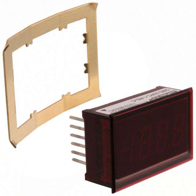
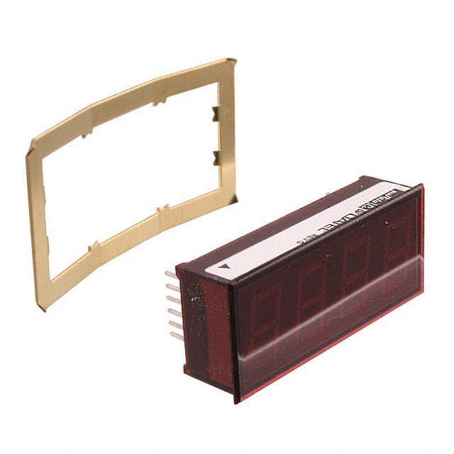
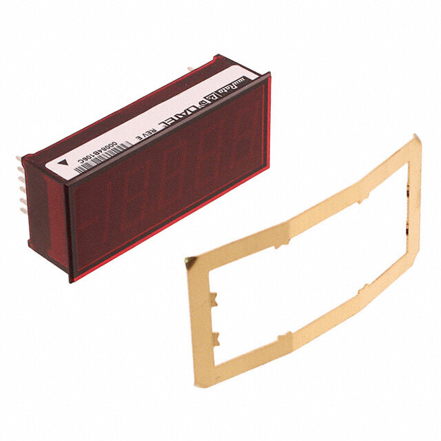
ICGOO电子元器件商城为您提供DMS-20PC-1-RS-C由Murata设计生产,在icgoo商城现货销售,并且可以通过原厂、代理商等渠道进行代购。 DMS-20PC-1-RS-C价格参考。MurataDMS-20PC-1-RS-C封装/规格:面板仪表, Voltage (Voltmeter) LED - Red Characters Display Panel Mount。您可以下载DMS-20PC-1-RS-C参考资料、Datasheet数据手册功能说明书,资料中有DMS-20PC-1-RS-C 详细功能的应用电路图电压和使用方法及教程。
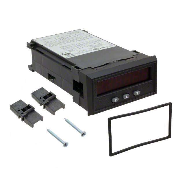
Murata Power Solutions Inc.生产的DMS-20PC-1-RS-C型号属于面板仪表类设备,其主要应用场景如下:

 1. 工业自动化领域
   - 该型号可应用于工业控制面板,用于显示和监控电压、电流或其他电力参数。例如,在生产线中实时监测电源状态,确保设备运行稳定。
   - 适用于PLC(可编程逻辑控制器)系统或SCADA(数据采集与监控系统),为操作人员提供直观的电力数据。

 2. 电力设备监测
   - 在配电柜、开关柜等电力设备中,用作电压表或电流表,帮助技术人员快速了解电路的工作情况。
   - 支持对关键电力参数进行精确测量,并可通过面板显示输出结果,便于故障诊断和维护。

 3. 实验室测试环境
   - 实验室中可用于测试电源模块、电池管理系统或其他电子设备的性能。其高精度和稳定性使其成为科研人员的理想选择。
   - 结合其他测试仪器,可以完成复杂的电力分析任务。

 4. 通信设备
   - 在通信基站或数据中心的电源管理系统中,作为面板仪表显示输入/输出电压、电流等信息,确保供电系统的可靠性。
   - 提供即时反馈以防止过载或异常情况发生。

 5. 医疗设备
   - 某些需要精密电源管理的医疗设备(如监护仪或诊断设备)可能会使用此类仪表来监控内部电源状态,保证设备安全运行。

 6. 新能源领域
   - 在太阳能逆变器、风能发电系统或其他可再生能源设备中,用作电源参数监测工具,优化能源转换效率。

 特点总结:
DMS-20PC-1-RS-C具有紧凑的设计、高精度测量能力和良好的耐用性,适合各种需要精准电力监测的场景。其易于安装和使用的特性进一步提升了其实用价值。
| 参数 | 数值 |
| 3D型号 | 点击此处下载产品Datasheethttp://www.murata-ps.com/3d/meters/mps_dpm_dms20.sldprthttp://www.murata-ps.com/3d/meters/mps_dpm_dms20.step.ziphttp://www.murata-ps.com/3d/meters/mps_dpm_dms20.igs |
| 产品目录 | |
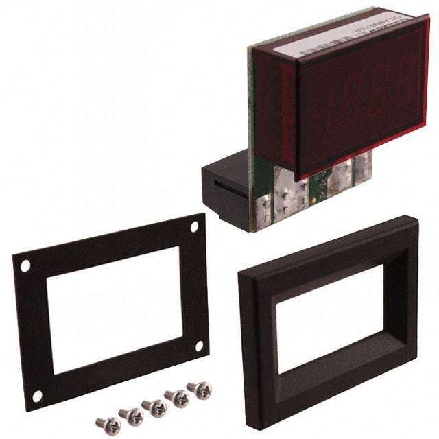
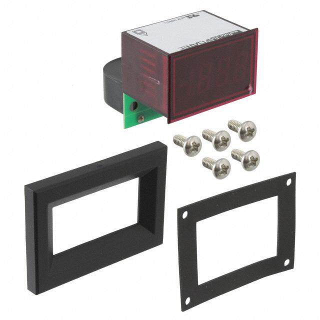
| 描述 | DPM LED 2VDC 3.5DIGIT RED数字面板表 3.5 Digit +-2V Input |
| 产品分类 | |
| 品牌 | Murata Power Solutions Inc |
| 产品手册 | |
| 产品图片 |
|
| rohs | RoHS 合规性豁免无铅 / 符合限制有害物质指令(RoHS)规范要求 |
| 产品系列 | 数字面板表,Murata Power Solutions DMS-20PC-1-RS-CDMS-20PC |
| 数据手册 | |
| 产品型号 | DMS-20PC-1-RS-C |
| 产品培训模块 | http://www.digikey.cn/PTM/IndividualPTM.page?site=cn&lang=zhs&ptm=16568 |
| 产品目录绘图 |
|
| 产品目录页面 | |
| 产品种类 | 数字面板表 |
| 侵入防护 | - |
| 其它名称 | 811-1001 |
| 商标 | Murata Power Solutions |
| 外壳宽度 | 35 mm |
| 外壳长度 | 12 mm |
| 外壳高度 | 22 mm |
| 安装类型 | 面板安装,后部安装夹 |
| 安装风格 | Panel, Board |
| 封装 | Bulk |
| 尺寸 | 12 mm L x 35 mm W x 22 mm H |
| 工作温度 | 0°C ~ 60°C |
| 工作电源电压 | 4.75 V to 5.25 V |
| 工作电源电流 | 60 mA |
| 工厂包装数量 | 12 |
| 描述/功能 | 5 V single power supply |
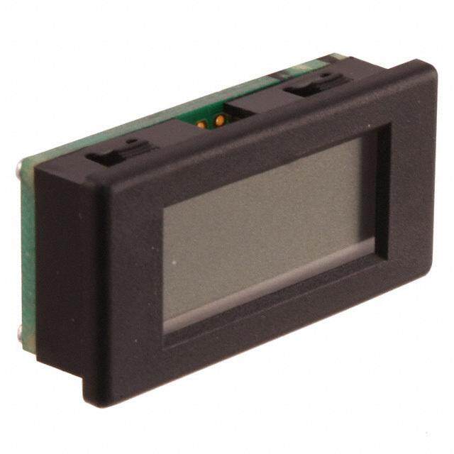
| 显示器类型 | LED, 3.5 Digit, Red |
| 显示字符- 高度 | 0.370"(9.40mm) |
| 显示数字 | 3.5 |
| 显示样式 | 红色字符,黑色背景 |
| 显示类型 | LED |
| 显示表面尺寸 | 1.83" 宽 x 1.28" 高 (46.4mm x 32.5mm) |
| 标准包装 | 12 |
| 校准 | 不需要 |
| 每行字符数 | 3.5 |
| 测量范围 | ±2V |
| 温度系数 | - |
| 特性 | - |
| 特色产品 | http://www.digikey.com/cn/zh/ph/muratapowersolutions/DMS20PC.html |
| 电压-电源 | 5VDC |
| 相关产品 | /product-detail/zh/5252-01127-0/811-2639-ND/3438622/product-detail/zh/DMS-EB2-C/811-1124-ND/1926167 |
| 端子类型 | PC 引脚 |
| 端接 | PC 引脚 |
| 类型 | 电压(电压表) |
| 精度 | - |
| 系列 | DMS-20PC |
| 设备类型 | Voltmeters |
| 输入电压 | +/- 2 V |
| 输出类型 | 基准 |
| 重量 | 0.024 磅(10.89g) |
| 零件号别名 | DMS-20PC-1-RS-C |
| 面板开口尺寸 | 矩形 - 33.93mm x 21.29mm |


- 商务部:美国ITC正式对集成电路等产品启动337调查
- 曝三星4nm工艺存在良率问题 高通将骁龙8 Gen1或转产台积电
- 太阳诱电将投资9.5亿元在常州建新厂生产MLCC 预计2023年完工
- 英特尔发布欧洲新工厂建设计划 深化IDM 2.0 战略
- 台积电先进制程称霸业界 有大客户加持明年业绩稳了
- 达到5530亿美元!SIA预计今年全球半导体销售额将创下新高
- 英特尔拟将自动驾驶子公司Mobileye上市 估值或超500亿美元
- 三星加码芯片和SET,合并消费电子和移动部门,撤换高东真等 CEO
- 三星电子宣布重大人事变动 还合并消费电子和移动部门
- 海关总署:前11个月进口集成电路产品价值2.52万亿元 增长14.8%
PDF Datasheet 数据手册内容提取
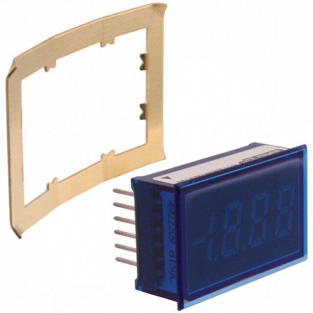
DMS-20PC Series www.murata-ps.com 3½ Digit, LED Display, Low-Cost, Subminiature Digital Panel Voltmeters New Laonwd- pgoreweenr LbEluDes FEATURES DMS-20PC Series, 3½ Digit, LED Display, Digital Panel Voltmeters combine a preci- Lowest-cost LED meters sion A/D converter; a factory-trimmed, highly stable, voltage reference; and a large (0.37"/9.4mm), easy-to-read LED display in a single package that is only slightly larger Subminiature size: than the display itself. Displays are offered in either red, orange, amber, yellow, green or 1.38" x 0.88" x 0.48" (35mm x 22mm x 12mm) blue colors. High-intensity and low-power (35mW total) red LEDs are also optional. Large (0.37"/9.4mm) LED display These low-cost meters are fully self-contained and fully functional. Their subminiature Choice of 6 LED colors (1.38" x 0.88" x 0.48"), epoxy-encapsulated cases incorporate built-in color fi lters and bezels; are moisture and vibration proof; and function well in the harshest environments. High-intensity or low-power (7mA) red LEDs optional Their 12-pin, dual-in-line confi guration offers component-like, plug-in convenience and Epoxy-encapsulated, 12-pin DIP package with built-in maximum versatility. Operating temperature range is 0 to +60°C. color fi lter and bezel The meters come with one of four, differential, input voltage ranges: ±200mV, ±2V 4 differential input voltage ranges ±20V or ±200V. Input impedance is a minimum 800kΩ. CMRR is typically 86dB (dc to 60Hz), and CMV is ±2V. Input overvoltage protection (on the non-inverting input) is ±250V. Factory calibrated, ±1 count accuracy Devices are fully calibrated at the factory to an accuracy of ±1 count (±0.05% of full scale Single +5V power supply range) and never require calibration or adjustment. User-selectable decimal point placement A DISPLAY ENABLE function permits the display to be disabled for "power-down" operation. All models have a DISPLAY TEST function. Standard red LED models offer an DISPLAY ENABLE function for "power-down" mode optional DISPLAY HOLD function. DISPLAY TEST and HOLD (optional) functions Small size, low cost and adjustment-free reliability make the DMS-20PC Series the best 0 to +60°C temperature range choice for all your 3½ digit, LED, DPM applications. SIMPLIFIED SCHEMATIC DIAGRAM +5V 1 V+ 12 +5V SUPPLY (–) INPUT LO 0.012 R2 1 –5V µF DISPLAY 2 DC/DC R1 1111 (+) INPUT HI ENABLE CONVERTER V– 909k »+2.0V 3 A/D 10 ANALOG 5V RETURN 0 Vdc CONVERTER COMMON DATA 4 9 DISPLAY 3 DP 3 TEST/HOLD 5 8 DP 2 +5V REFERENCE OUT 6 7 DP 1 REFERENCE IN 1 R2 is not used on ±200mV (-0) models or ±2V (-1) models. 2 Only used on ±200mV (-0) and ±2V (-1) models. R2 = 100k on ±20V (-2) models and 9.1k on ±200V (-3) models. 3 Pin 9 is DISPLAY TEST on all but eight models. On those models (-H option), it is DISPLAY HOLD. For full details go to www.murata-ps.com/rohs Figure 1. DMS-20PC Series simplifi ed schematic www.murata-ps.com/support MPM_DMS_20PC.F01 Page 1 of 6
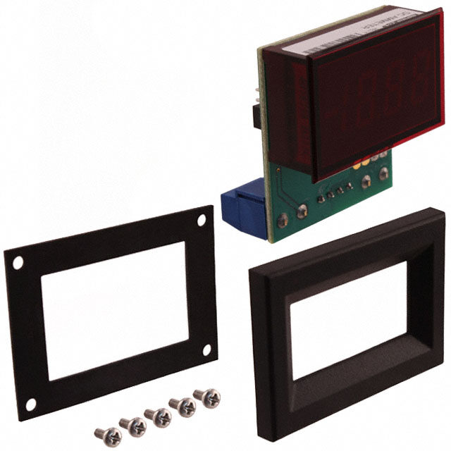
DMS-20PC Series 3½ Digit, LED Display, Low-Cost, Subminiature Performance/Functional Specifi cations Digital Panel Voltmeters Typical at TA = +25°C and supply voltage = +5V using the single-ended input circuit, unless otherwise noted. Analog Inputs Min. Typ. Max. Units Ordering Information Full Scale Input Range: DMS-20PC - 1 - RS -C DMS-20PC-0 – ±200 – mV Add -C for RoHS DMS-20PC-1 – ±2 – Volts Input Range: 0 = ±200mV Leave blank for standard DMS-20PC-2 – ±20 – Volts 1 = ±2V models. DMS-20PC-3 – ±200 – Volts 2 = ±20V Add -H for DISPLAY HOLD Input Impedence: 3 = ±200V option (available on standard red and green DMS-20PC-0, -1 – 1000 – MΩ LED models only). DMS-20PC-2, -3 – 1 – MΩ LED Color: Overvoltage Protection ➀ – – ±250 Volts AS = Standard Amber RS = Standard Red BS = Standard Blue YS = Standard Yellow Common Mode Voltage Range – – ±2 Volts GS = Standard Green RH = High-Intensity Red CMRR (dc to 60Hz) – 86 – dB OS = Standard Orange RL = Low-Power Red BL = Low-Power Blue Performance PGL = Low-Power Green Sampling Rate 2.5 reading per second Accessories: Accuracy (3 minute warm-up): DMS-20-CP Panel cutout punch DMS-BZL3-C DMS-20 bezel assembly DMS-20PC-0 (Vin = +0.19V) – ±1 ±3 Counts DMS-BZL4-C DMS-20 bezel assembly with sealing gasket DMS-20PC-1 (Vin = +1.9V) – ±1 ±3 Counts DMS-EB2-C Application/evaluation board with standard MOLEX connector, decimal point solder pads and attenuation DMS-20PC-2 (Vin = +19V) – ±2 ±3 Counts resistor pads. DMS-20PC-3 (Vin = +190V) – ±2 ±3 Counts A panel-mount retaining clip is supplied with each model. Zero Reading (Vin = 0 Volts) “–001” “000” “001” Temperature Drift (0 = +60°C) – ±0.2 ±0.4 Cnts/°C See www.murata-ps.com/dpm-availability for model-specifi c availability. Power Supply Requirements Supply Voltage +4.75 +5.00 +5.25 Volts TECHNICAL NOTES Supply Current: RoHS Compliant Parts: Add "-C" suffi x to part number. 1. REFERENCE OUTPUT (Pin 8) and INPUT (Pin 7): Pin 8 is a precision DMS-20PC-X-RL – +7 +12 mA reference actively trimmed at the factory. In normal operation, pin 8 DMS-20PC-X-BL & -PGL – +12 +17 mA must be tied to pin 7 to achieve all listed accuracy and drift specifi ca- DMS-20PC-X-RS, -RH – +60 +90 mA tions. DMS-20PC-X-RS-H – +60 +90 mA 2. ANALOG COMMON (Pin 10): This pin is connected to an internal, DMS-20PC-X-BS – +75 +100 mA low-noise, "relative" ground. It is used in certain differential and DMS-20PC-X-GS-H – +90 +120 mA "fl oating" measurements as described in the Applications section DMS-20PC-X-AS, -GS, -OS, -YS – +90 +120 mA of this data sheet and Ap Note DMS-AN3 at Display http://www.murata-ps.com/data/meters/dms-an3.pdf. Pin 10 should not be connected to pin 3 (5V RETURN) or to your system’s analog Display Type and Size 3½ digit, 0.37"/9.4mm high LED ground. Polarity Indication Autopolarity ("–" for negative Vin) 3. Decimal Point Placement: The location of the decimal point is user- Overrange Indication "–1___" for negative inputs selectable, and the decimal point control pins (DP1-DP3) are active "1___" for positive inputs low functions. Select the appropriate decimal point by tying the Physical/Environmental appropriate pin (pin 4, 5 or 6) to pin 3 (5V RETURN). Unused decimal Operating Temperature 0 – +60 °C point location pins should be left open. Storage Temperature –20 – +75 °C Hard wiring is preferable, however, you can use logic gates to Humidity (non-condensing) 0 – 95 % exercise dynamic control over the location of the decimal point if the Case Material Polycarbonate following drive conditions are met: Weight 0.4 ounces (11 grams) Model Applied "0" Voltage Load Current* ➀ Applies for transient or continuous overvoltages applied to (+) INPUT HI (pin 11) DMS-20PC-X-XL +0.05V max. 0.7mA max. with (–) INPUT LO (pin 12) properly connected. Pin 12 is not overvoltage protected (see Figure 1). Voltages applied to pin 12 should not exceed the supply voltage. All Others +0.4V max. 6mA max. ➁ See Technical Notes. * The driving gates must be able to sink this much current ➂ The DISPLAY HOLD function is optional on standard red and green LED models only. www.murata-ps.com/support MPM_DMS_20PC.F01 Page 2 of 6
DMS-20PC Series 3½ Digit, LED Display, Low-Cost, Subminiature Digital Panel Voltmeters 4. DISPLAY TEST/HOLD (Pin 9) Function: Pin 9 is a dual-function 8. Suggested Mating Connectors: pin. On all standard models (without "-H" suffi x), tying pin 9 to pin 1 Panel mounted: (+5V SUPPLY) activates the meter's DISPLAY TEST feature. All display Connector housing Murata Power Solutions P/N 4320-01069-0 segments, except the decimal points, will be illuminated. The display Terminal type Murata Power Solutions P/N 4400-01032-0 will show "1888" ("–1888" if a negative input signal is present). Do Crimping tool Murata Power Solutions P/N 39-2099000 not leave the meter in the test mode for more than 10 seconds as Wire size 22 to 26 AWG this will cause the meter's operating temperature to rise and possibly affect its performance. Pin 9 must be left open when the test function Insulation diameter 0.062" (1.57mm) maximum is not being used. Stripping length 0.100 to 0.125" (2.54 to 3.17mm) Board mounted: On models with the "-H" suffi x (DMS-20PC-1-RS-H for example), pin Socket Murata Power Solutions P/N 4320-01074-0 9 serves as a DISPLAY HOLD control pin. Tying pin 9 to +5V SUPPLY (pin 1) on these models will hold or "freeze" the current display read- APPLICATIONS ing indefi nitely. Pin 9 must also be left open when the hold function is not being used. After disabling DISPLAY HOLD, allow the meter a full DMS-20PC meters are highly versatile devices that can be used in 10 seconds to resume normal calibrated operation before holding a hundreds of applications. The application circuits chosen for this section new reading. are ones that have historically received many inquiries. The DISPLAY TEST or DISPLAY HOLD pin should normally be con- The schematic in Figure 1 shows that the meter's high-impedance input nected, via a selector switch, to pin 1 (+5V SUPPLY). If automatic, consists of an op amp powered from a ±5Vdc power supply (the –5V is logic-controlled operation is desired, only PNP or MOSFET transis- internally generated). One can easily see why input signals applied to (–) tors should be used. The base or gate of these transistors should be INPUT LO and (+) INPUT HI have to be kept within the power supply rails driven suffi ciently hard to bring pin 9 within 0.05V of +5V SUPPLY. of ±5V. Also note that only pin 11 has a current-limiting 909kΩ series 5. DISPLAY ENABLE (Pin 2) Function: On all models, tying pin 2 to resistor. High input voltages that have a common ground with pin 3 (5V pin 1 (+5V SUPPLY) applies full power to the LED display. This is the RETURN) should only be applied to pin 11 ((+) INPUT HI) and never to pin normal mode of operating the meter. Leaving DISPLAY ENABLE open 12. In these high-voltage cases, pin 12 should always be tied to pin 3 (no connection), only turns off the LED display. The meter's analog- (5V RETURN). to-digital converter continues to sample the input signal. Total current The schematic also shows that pin 3 is the meter's zero-volt reference consumption with the display off is approximately 400μA (0.4mA). point — regardless of the type of power or signal source used. This is This is a very useful feature if the meter is used in battery-powered an important point to keep in mind when a digital or analog multimeter equipment. is used to make system measurements. The multimeter's negative lead With the exception of the low-power red LED models (DMS-20PC-X- (usually the black one) must be connected to pin 3 (5V RETURN). RL), a regulated voltage lower than +5V SUPPLY can be used to dim the display intensity. Display intensity control is best performed with 1. Single-Ended Input Confi gurations: True single-ended measure- the high brightness, red LED, DMS-20PC-X-RH model. All low-power ments can be made with any DMS-20PC meter. The circuit of Figure red LED models must have DISPLAY ENABLE tied directly to pin 1 2 avoids problems normally associated with ground-loop currents. (+5V SUPPLY). Voltages applied to DISPLAY ENABLE must never be Separate ground runs should be used for 5V RETURN (pin 3) and (–) greater than +5V SUPPLY. INPUT LO (pin 12). 6. Gain Adjust: There is a gain-adjust potentiometer on the back of each meter. It has approximately ±50 counts (±2.5%) range of DMS-20PC-1 adjustment. Since these devices essentially have no zero/offset 11 8 errors, a gain adjustment is effectively an overall accuracy adjust- (+) IN HI REF OUT + ment. Though they may be performed at any point (except zero), accuracy adjustments are most effective when performed with VIN higher level input signals. The circuit shown in Figure 10 provides – 12 7 ±10% range of adjustment. (–) IN LO REF IN 7. Soldering Methods: All models in the DMS-20PC Series easily with- 1 2 6 3 stand most common wave soldering operations. We recommend, +5V SUP DISPLAY DP1 5V RET ENABLE however, that you evaluate the effects your particular soldering techniques may have on the meter’s plastic case and high-precision 85-264Vac electrical performance. We recommend the use of no-clean solders. AC to DC Converter Figure 2. Single-Ended Input Confi guration www.murata-ps.com/support MPM_DMS_20PC.F01 Page 3 of 6
DMS-20PC Series 3½ Digit, LED Display, Low-Cost, Subminiature Digital Panel Voltmeters APPLICATIONS 2. Differential Input Confi gurations: Differential measurements 4. Floating Signal Source Measurements: Floating signals can be can be made with all DMS-20PC meters. Figure 3, though not measured using the circuits shown in Figures 5 and 6. Connecting a practical real-world application, uses a voltage divider to pin 10 (ANALOG COMMON) or pin 3 (5V RETURN) to (–) INPUT LO demonstrate the concept of a differential input signal. Be care- (pin 12) provides the reference point for the meter’s input. ful not to exceed the ±2V common mode voltage limitation for A "fl oating" input is a signal that has no galvanic connection to 5V-powered meters. the meter's power supply. In the fi gures below, the 1.5V battery illustrates a true fl oating input. R1 DMS-20PC-1 11 REF OUT 8 (+) IN HI 1k 11 DMS-20PC-1 (+) IN HI 8 REF OUT R2 + REF IN 7 12 1k 1.5V DP1 6 (–) IN LO CELL – (–) IN L1O2 7 R3 REF IN +5V SU1P 2DISPLAY 53V RET 1k 1 2 3 6 ENABLE +5V SUP DISPLAY 5V DP1 ENABLE RET 85-264Vac 85-264Vac AC to DC Converter AC to DC Converter Figure 3. Differential Input Confi guration Figure 5. Floating Input Measurements 3. Engineering Scaling: For measuring voltages greater than DMS-20PC-1 the full scale input range of a given meter, the input signal 11 (+) IN HI 8 must be attenuated. A simple voltage divider (similar to that REF OUT + 10 shown in Figure 4) will scale the input to within the range of 1.5V ANA COMM CELL the selected meter. R1 and R2 should be precision, ±1%, – 12 metal-fi lm resistors with absolute TCR's less than 50ppm/°C. 7 (–) IN LO REF IN See Ap Note 4 for more information on engineering scaling. 1 2 3 6 +5V SUP DISPLAY 5V DP1 ENABLE RET 50kΩ < R1 + R2 < 10MΩ R2 85-264Vac x V = Reading IN R1 + R2 AC to DC Converter Figure 6. Floating Input Measurements + (Alternate Confi guration) R1 DMS-20PC-1 11 (+) IN HI 8 VIN REF OUT 5. Process Control (4-to-20mA) Measurements: In many common R2 process-control applications, a 4-to-20mA current loop is used to 12 (–) IN LO transmit information. Because DMS-20PC meters have such high – 7 REF IN input impedance, a simple shunt resistor across the meter's input 1 2 3 can be used to convert the loop current to a voltage. See Figure 7. +5V SUP DISPLAY 5V RET ENABLE The value of the shunt resistor is a function of the scaling require- ments of the particular application and can be calculated using 85-264Vac the following equation: R = R1 = V /I AC to DC Converter Shunt Fsr Fsr Figure 4. Input Attenuation Circuit Where: VFsr = Full scale reading (in Volts) I = Relative full scale current (in Amps) Fsr www.murata-ps.com/support MPM_DMS_20PC.F01 Page 4 of 6
DMS-20PC Series 3½ Digit, LED Display, Low-Cost, Subminiature Digital Panel Voltmeters APPLICATIONS Example: For a meter with a 2V full scale input (1.999 full scale The LM-2931 was chosen because it has the following on-chip reading) and a desired display reading of "1000" (with an protection features: reverse polarity, short circuit and thermal input of 20mA), VFsr = 1.000 Volts runaway. When using other, higher-power, DMS-20PC models with three-terminal regulators, be sure to consult the regula- R = 1.000V/(0.020 – 0.004)A Shunt tor manufacturer's data sheet to ensure the regulator is being R = 1.000V/0.016A = 62.5 Ohms Shunt utilized safely and correctly. To calibrate the circuit of Figure 7, perform the following: 7. Digital Ammeter: Digital ammeters are fi nding ever-increasing usage because analog-style ammeters (moving-vane types) 1. With 4mA applied, adjust the 50kΩ potentiometer (R2) to now cost roughly the same as their digital counterparts. Addi- display a reading of "000" (assuming that is the desired tionally, analog ammeters are not nearly as rugged as modern reading). digital panel voltmeters. Figure 9 illustrates a typical ammeter 2. With 20mA applied, adjust the gain-adjust potentiometer application. The circuit uses a ±200mV input meter — the on the back of the meter to display a reading of "1000". preferred range for most ammeters — to measure the voltage For different full scale readings, alter the value of R Shunt developed across a 0.1Ω current shunt. The circuit shown accordingly. represents a bhastitcp a:/m/wmwetewr .cmonunreacttaio-np sd.icagormam/d. aCtliack/m heertee rtos /dms-an6.pdf view a detailed application note describing digital dc ammeters. DMS-20PC-1 11 (+) IN HI 8 + REF OUT 10 ANA COMM 1 DMS-20PC-0 +5V SUP 12 8 4-20mA R1 (–) IN LO R7EF IN + DISP EN2 REF OUT 5Vdc 1 2 3 3 – R2 +5V SUP DISPLAY 5V RET 5V RET – ENABLE 7 50k 6 REF IN DP1 12 11 (–) IN LO (+) IN HI 85-264Vac 0.150V 1.5 Amp (Load Current) AC to DC Converter 0.1W Load RShunt (3.3 W ) Figure 7. 4-to-20mA Current Loop Operation Figure 9. Basic DC Ammeter Circuit 6. Power Supply Monitoring: One of the most common digital panel meter applications involves monitoring the output voltage 8. External Gain Adjustment: Connect REFERENCE OUT of the system power supply — often this supply also powers the (pin 8) to REFERENCE IN (pin 7) for normal, factory calibrated, meter itself. The low-power, red LED DMS-20PC-2-RL can be operation. Use the circuit shown in Figure 10 for applications confi gured to allow power supply monitoring over the range of needing external gain adjustment. Calibration is performed 4.5-18Vdc. The circuit in Figure 8 uses a low-drop-out, three-ter- with a precise, near-full-scale, input voltage. minal regulator (LM-2931Z-5, available from National Semicon- ductor) to provide regulated 5V-power to the meter. 11 DMS-20PC-1 (+) IN HI OUT 3 1 DMS-20PC-2-RL 12CAVLOIBLTRAAGTEOR 5V RET +5V IN LM2931Z-5 12 IN OUT +5V SU12P 11(+) IN HI COM (–) IN LOAN1A0 NC8 REF7 anfdoC r±o 2±n02n0VeVc, t ±imo2no0sdVels + GND + DISP EN COMM IN 4.5 - 18Vdc 22µF 3 8.06k, 1% 2k1 17.4k, 1% – 10V 5V RET 5 DP2 REF7 8REF (1–2) IN LO 732, 1% 2001 24.3k, 1% Cfoormn ±no2ed0ce0tlismonVs IN OUT 1= 10 to 20 Turns Figure 10. External Gain Adjustment Figure 8. 4.5-18V Power Supply Monitor www.murata-ps.com/support MPM_DMS_20PC.F01 Page 5 of 6
DMS-20PC Series 3½ Digit, LED Display, Low-Cost, Subminiature Digital Panel Voltmeters MECHANICAL SPECIFICATIONS MECHANICAL DIMENSIONS: Inches (mm) TOLERANCES: 2 PL DEC ±0.02 (±0.51) PIN #1 3 PL DEC ±0.010 (±0.254) IDENTIFIER LEAD DIMENSIONS: 0.025 (0.635) x 0.025 (0.635) NOMINAL ASU NI EDAM XX-X-CP02-SMD RECOMMENDED PC BOARD FINISHED HOLE DIAMETER: 0.042 ±0.003 (1.067 ±0.076) CALIBRATION POTENTIOMETER HOLE LOCATION FRONT VIEW PIN 1 0.170 +5V SUPPLY 1 12 (–) INPUT LO (4.32) DISPLAY ENABLE 2 11 (+) INPUT HI 5V RETURN 3 10 ANALOG COMMON DP3 4 9 DISPLAY TEST/HOLD DP2 5 8 REFERENCE OUT DP1 6 7 REFERENCE IN 0.150 DP1 DP2 DP3 (3.81) 0.125 (3.175) DIAMETER 0.88 1.38 (USE ONLY WHEN (22.4) (35.1) PC BOARD MOUNTING) 0.80 1.30 (20.3) (33.0) 0.475 (12.07) 0.040 (1.02) 0.25 (6.4) TYP. 0.040 (1.0T(023Y.).18P5.) 0.50 T(02Y..15P0.) (01..00420) (12.71.09) T(02Y..15P0.) (12.7) BEZEL INSTALLATION AND RECOMMENDED DRILL AND PANEL CUTOUT #2-56 INSERT 0.187 0.156 (3.96) DEEP (4.75) FRONT VIEW (13.22.8501) 1.826 (46.38) 0.116 (2.95) INTERNAL CORNER RADII: 0.032 (0.81) MAX. PANEL 1.07 0.838 (27.18) PANEL CUTOUT (21.29) 0.093 (2.362) DIA 1.336 (33.93) 0.145 (3.68) (4 REQUIRED) 1.626 (41.30) BEZEL This product is subject to the following operating requirements Murata Power Solutions, Inc. and the Life and Safety Critical Application Sales Policy: 11 Cabot Boulevard, Mansfi eld, MA 02048-1151 U.S.A. Refer to: http://www.murata-ps.com/requirements/ ISO 9001 and 14001 REGISTERED Murata Power Solutions, Inc. makes no representation that the use of its products in the circuits described herein, or the use of other technical information contained herein, will not infringe upon existing or future patent rights. The descriptions contained herein do not imply the granting of licenses to make, use, or sell equipment constructed in accordance therewith. Specifi cations are subject to change without notice. © 2015 Murata Power Solutions, Inc. www.murata-ps.com/support MPM_DMS_20PC.F01 Page 6 of 6
Mouser Electronics Authorized Distributor Click to View Pricing, Inventory, Delivery & Lifecycle Information: M urata: DMS-20PC-3-DCM DMS-20PC-1-LM-GF DMS-20PC-0/5-24RL DMS-20PC-1-LM-BF DMS-20PC-1-BS DMS-20PC- 1-RS DMS-20PC-1-RL DMS-20PC-1-RH DMS-20PC-2-RS-H DMS-20PC-2-GS-H DMS-20PC-1-AS DMS-20PC-1- LM DMS-20PC-1-GS DMS-20PC-1-YS DMS-20PC-1-FM DMS-20PC-0-RS-H DMS-20PC-0-GS-H DMS-20PC-4- DCM DMS-20PC-3-RS-H DMS-20PC-1-FM-F DMS-20PC-0-DCM DMS-20PC-2-YS DMS-20PC-2-AS DMS-20PC-2- GS DMS-20PC-1-GS-H DMS-20PC-2-LM DMS-20PC-2-RS DMS-20PC-2-RL DMS-20PC-2-RH DMS-20PC-2-BS DMS-20PC-2-FM DMS-20PC-1-LM-G DMS-20PC-1-LM-B DMS-20PC-1-LM-F DMS-20PC-4/20S DMS-20PC-3-FM DMS-20PC-3-BS DMS-20PC-3-YS DMS-20PC-3-RS DMS-20PC-3-GS DMS-20PC-3-LM DMS-20PC-3-RH DMS- 20PC-3-RL DMS-20PC-7-DCM DMS-20PC-0-OS DMS-20PC-0-AS DMS-20PC-1-LM-R DMS-20PC-0-BS-C DMS- 20PC-0-GS-C DMS-20PC-0-GS-H-C DMS-20PC-0-RH-C DMS-20PC-0-RL-C DMS-20PC-0-RS-C DMS-20PC-0-RS- H-C DMS-20PC-0-YS-C DMS-20PC-1-BS-C DMS-20PC-1-GS-C DMS-20PC-1-GS-H-C DMS-20PC-1-RH-C DMS- 20PC-1-RL-C DMS-20PC-1-RS-C DMS-20PC-1-RS-H-C DMS-20PC-1-YS-C DMS-20PC-2-BS-C DMS-20PC-2-GS- C DMS-20PC-2-GS-H-C DMS-20PC-2-RH-C DMS-20PC-2-RL-C DMS-20PC-2-RS-C DMS-20PC-2-RS-H-C DMS- 20PC-2-YS-C DMS-20PC-3-BS-C DMS-20PC-3-GS-C DMS-20PC-3-RH-C DMS-20PC-3-RL-C DMS-20PC-3-RS-C DMS-20PC-3-RS-H-C DMS-20PC-3-YS-C DMS-20PC-1-RS-H DMS-20PC-0-DCM-B DMS-20PC-1-DCM-B DMS- 20PC-2-DCM DMS-20PC-1-DCM DMS-20PC-6-DCM DMS-20PC-4/20B DMS-20PC-4/20P DMS-20PC-5-DCM DMS-20PC-0/5-5BS DMS-20PC-0/5-5RS DMS-20PC-0/5-5RH DMS-20PC-0/5-5RL DMS-20PC-0/5-5GS DMS-20PC- 0-YS DMS-20PC-0-GS DMS-20PC-0-BS DMS-20PC-0-RL DMS-20PC-0-RH DMS-20PC-0-RS DMS-20PC-8-DCM DMS-20PC-0-BL-C