ICGOO在线商城 > 连接器,互连器件 > 存储器连接器 - PC 卡插槽 > DM3AT-SF-PEJM5
 Datasheet下载
- 型号: DM3AT-SF-PEJM5
- 制造商: Hirose Electric
- 库位|库存: xxxx|xxxx
- 要求:
| 数量阶梯 | 香港交货 | 国内含税 |
| +xxxx | $xxxx | ¥xxxx |
查看当月历史价格
查看今年历史价格
DM3AT-SF-PEJM5产品简介:
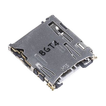
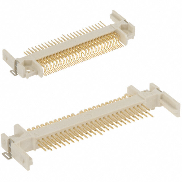
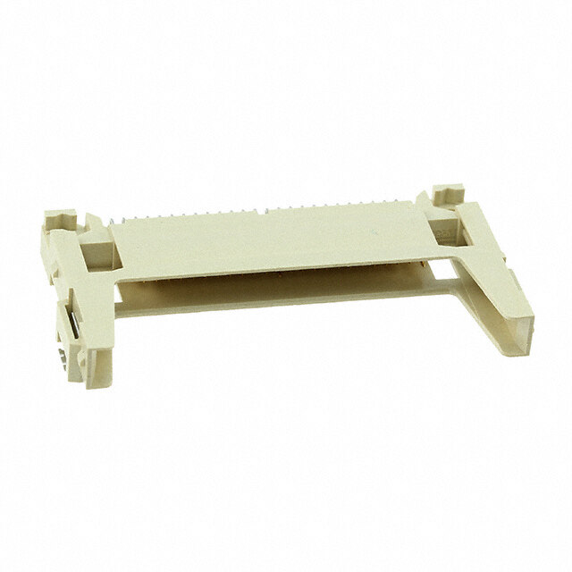
ICGOO电子元器件商城为您提供DM3AT-SF-PEJM5由Hirose Electric设计生产,在icgoo商城现货销售,并且可以通过原厂、代理商等渠道进行代购。 DM3AT-SF-PEJM5价格参考¥8.01-¥15.14。Hirose ElectricDM3AT-SF-PEJM5封装/规格:存储器连接器 - PC 卡插槽, 10 (8 + 2) Position Card Connector Secure Digital - microSD™ Surface Mount, Right Angle Gold。您可以下载DM3AT-SF-PEJM5参考资料、Datasheet数据手册功能说明书,资料中有DM3AT-SF-PEJM5 详细功能的应用电路图电压和使用方法及教程。
Hirose Electric Co Ltd的DM3AT-SF-PEJM5是一款存储器连接器,属于PC卡插槽类型,主要用于支持小型化、高可靠性的数据存储与扩展应用。该连接器符合行业标准,适用于需要插入PCMCIA(个人计算机存储卡国际协会)卡或类似存储模块的设备。

其典型应用场景包括工业控制设备、便携式医疗仪器、测试测量仪器以及嵌入式系统等对空间紧凑和连接稳定性要求较高的领域。例如,在工业手持终端或现场数据采集设备中,DM3AT-SF-PEJM5可支持存储卡的快速插拔,实现数据的便捷传输与扩展存储。同时,该连接器具备良好的耐久性和抗振动性能,适合在复杂环境或移动使用条件下保持稳定连接。

此外,该产品也适用于部分通信设备和车载电子系统,用于扩展内存或连接功能模块。其结构设计确保了精确的卡件定位和可靠的电气接触,提升了整体系统的运行可靠性。由于Hirose品牌一贯注重高品质与精密制造,DM3AT-SF-PEJM5在长期使用中表现出色,是许多高性能电子设备中的理想选择。
| 参数 | 数值 |
| 产品目录 | |
| 描述 | CONN MICRO SD R/A PUSH-PUSH SMD记忆卡连接器 R/A SMT MICROSD CON PUSH-PUSH TOP BRDMNT |
| 产品分类 | 存储器连接器 - PC 卡存储器连接器 |
| 品牌 | Hirose Electric Co Ltd |
| 产品手册 | |
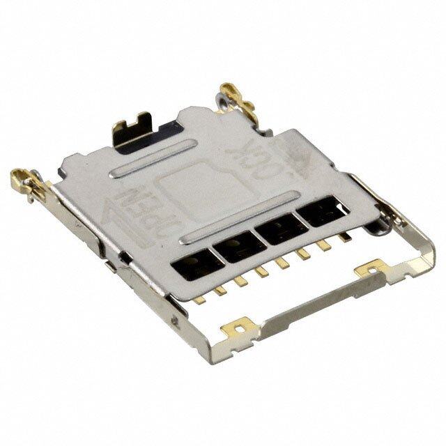
| 产品图片 |
|
| rohs | 符合RoHS无铅 / 符合限制有害物质指令(RoHS)规范要求 |
| 产品系列 | 记忆卡连接器,Hirose Connector DM3AT-SF-PEJM5DM3 |
| 数据手册 | |
| 产品型号 | DM3AT-SF-PEJM5 |
| 产品 | Card Connectors |
| 产品培训模块 | http://www.digikey.cn/PTM/IndividualPTM.page?site=cn&lang=zhs&ptm=2640 |
| 产品种类 | 记忆卡连接器 |
| 其它名称 | DM3ATSFPEJM5 |
| 包装 | 带卷 (TR) |
| 卡类型 | 安全数字式 - microSD™ |
| 可燃性等级 | UL 94 V-0 |
| 商标 | Hirose Connector |
| 外壳材料 | Liquid Crystal Polymer (LCP) |
| 安装特性 | 正常,标准 - 顶部 |
| 安装类型 | 表面贴装,直角 |
| 封装 | Reel |
| 工厂包装数量 | 1500 |
| 弹出器端 | - |
| 排数 | 1 |
| 插入-取出类型 | Push-Push |
| 插入,拆除方法 | 推入式,推出式 |
| 方向 | Horizontal |
| 板上高度 | 0.066"(1.68mm) |
| 标准包装 | 1,500 |
| 特性 | |
| 特色产品 | http://www.digikey.cn/product-highlights/zh/hirose-electric-dm3at-series/52061 |
| 电压额定值 | 125 V |
| 电流额定值 | 500 mA |
| 端接类型 | SMD |
| 系列 | DM3 |
| 节距 | 1.06 mm |
| 触头镀层 | 金 |
| 触头镀层厚度 | - |
| 触点数量 | 8 |
| 触点材料 | Copper Alloy |
| 运转周期 | 10 k |
| 连接器类型 | 连接器和弹出器 |
| 针脚数 | 10(8 + 2) |
| 长度 | 15.95 mm |
| 高度 | 1.68 mm |


.jpg)
.jpg)


PDF Datasheet 数据手册内容提取
microSD™ Card Connectors DM3 Series d. e v r e s e R s ht g Ri All D. T ■ L Features O., ◆ Common to the entire Series ◆ DM3D (Push -Pull, manual, without C C 1. Extremely small in size ejection mechanism) RI Small external dimensions and the above-the-board height · Partial card insertion hold T C make the connectors the smallest on the market. Card will not fall-out even when it is not fully inserted. Full E 2. Reverse card insertion protection insertion and electrical / mechanical connection is confirmed L with a distinct tactile feel. E Unique card slot design (patented) protects the connector E from damage when the card is attempted to be inserted in · Accessible termination areas S O reverse, allowing it to re-inserted correctly. An inner lead system that can be reworked is used in this design. R 3. Effective ground and shield configuration Contact solder terminations may be inspected and reworked. HI 8 4-connection points of the metal cover to the printed circuit 1 board assures secure connection of the ground circuit and 0 2 provides EMI protection. ht 4. Rigid and strong construction g ri Despite its small size, high-strengths materials used in the y p connectors produced a strong and rigid structure. o C 5. Card detection switch Card insertion-ejection Series Image Page 8 The card detection switch is Normally Open 1 0 2 1. ◆ DM3AT and DM3BT (Push - Push, with c. ejection mechanism) DM3AT 2~4 e D · Card fall-out prevention Built-in card tray and the unique push insertion-push ejection mechanism (patented) prevent accidental card ejection or fall- Push-Push out. Despite its small size the connectors will eject the card to a distance of 4.0mm, allowing easy hold and removal of the card. DM3BT 5~6 · Exposed termination leads Easy inspection and rework of the solder termination joints. ◆ DM3CS (Hinge, Push-Pull, manual, without ejection mechanism) · Simple and reliable card insertion Hinge-manual insertion/ DM3CS 7~8 Hinged metal cover provides location and guides the card ejection during the insertion / removal. Closing of the cover confirms the electrical and mechanical connection with a tactile click sensation. · Reliable contact with the card contact pads Unique contact design and card slide action will clean the Push-Pull contact areas of the card. manual insertion/ DM3D 9~10 ejection · Accessible termination areas Contact solder terminations may be inspected and reworked. 2017.1③ 1
DM3 Series●microSD™Card Connectors ■Product Specifications (DM3 Series) Current rating : 0.5A Operating temperature range : -25ç to +85ç (Note 1) Operating humidity range : RH 95% max. Ratings Voltage rating : 125V AC Storage temperature range : -40ç to +85ç (Note 2) (No condensation) Item Specification Conditions 1. Insulation resistance 1000Mø min. (Initial value) Measure at 500V DC 2. Withstanding voltage No flashover or insulation breakdown 500 V AC / 1 minute 3. Contact resistance 100mø max. (Initial value) 1mA No electrical discontinuity of 100 ns or longer Frequency : 10 to 55Hz, single amplitude of 0.75mm, 4. Vibration No damage, cracks or parts dislocation. 3 directions for 2 hours d. Contact resistance : 40mø max. (change from initial value) e v 5. Humidity Insulation resistance : 100Mø min. 96 hours at of 40 ± 2ç, and humidity of 90 to 95% r e s No damage, cracks or parts dislocation. e R s Contact resistance : 40mø max. (change from initial value) -55ç ➝5 to 35ç ➝85ç ➝5 to 35ç ht 6. Temperature cycle Insulation resistance : 100Mø min. Times : 30 min. ➝5 min. ➝30 min. ➝5 min. g Ri No damage, cracks or parts dislocation. 5 cycles All D. 7. Durability Contact resistance : 40mø max. (change from initial value) 10,000 cycles, 400 to 600 cycles per hour (DM3AT, DM3B) 5,000 cycles, 400 to 600 cycles per hour (DM3C, DM3D) T L O., 8. Resistance to No deformation of components affecting performance. Reflow : At the recommended temperature profile soldering heat Manual soldering : 350ç for 3 seconds C C Note 1 : Includes temperature rise caused by current flow. RI Note 2 : The term "storage" refers to products stored for long period prior to mounting and use. T C E ■Materials / Finish L E E DM3AT, DM3BT S O Part Material Finish Remarks R HI Insulator LCP Color : Black UL94V-0 8 Contact area : Gold plated 1 Contacts Copper alloy ------------------- 0 Lead area : Gold plated 2 ht Stainless steel (DM3AT) g Guide cover Lead area : Gold plated ------------------- ri Copper alloy (DM3BT) y p o Stainless steel (DM3AT, DM3BT) ------------------- C Other components ------------------- 8 Piano wire (DM3BT) Nickel plated 1 0 DM3CS, DM3D 2 1. Part Material Finish Remarks c. e D Insulator LCP Color : Black UL94V-0 Contact area : Gold plated Contacts Copper alloy ------------------- Lead area : Gold plated ------------------- (DM3CS) Guide cover Stainless steel ------------------- Tin plated (DM3D) ■Product Number Structure Refer to the chart below when determining the product specifications from the product number. Please select from the product numbers listed in this catalog when placing orders. DM3 AT – SF – PEJM5 1 2 3 4 1 Series name : DM3 3 Termination type : SF Right-angle SMT(Standard) 2 Connector type : AT Push-Push (ejection mechanism), Top board mounting (Standard) DSF Right-angle SMT(Reverse) BT Push-Push (ejection mechanism), Bottom board mounting (Reverse) 4 Card ejection code :PEJM5, PEJS CS Hinge, Push-Pull (no ejection mechanism), Top board mounting (Standard) (Push insert/push eject) D Push-Pull (no ejection mechanism), Top board mounting (Standard) None : Manual card Number of contacts : 8 insertion/ejection 2
DM3 Series●microSD™Card Connectors ■DM3AT Push-Push (ejection mechanism), Top board mounting (Standard) #5(CLK) #4(VDD) #6(VSS) #3(CMD) #7(DAT0) #2(CD/DAT3) #8(DAT1) #1(DAT2) 13.85 CARD DETECTION (7.35) 1.68 2 SWITCH(B) (3.2) ONN TIO erved. 5 5ROKE POSIK POSITIOSITION All Rights Res DM3APTa-rSt FN-PoE.JM5 6H09R-S00 N31o-.0 15.9 (15)15.9(16.75):CARD OVER ST(17.55):CARD LOC55):CARD EJECT P TD. 2 CSWARITDC DHE(AT)ECTION (21. (0.8) L O., microSD CARD (5.5) CL 1 C (11) C All dimensions : mm RI T C LE ■Recommended PCB mounting pattern 2.9±0.15 E E S 10MIN O 9.25MAX R 8.65 HI 7.7 8 0.7 1.55 1 1 N P=1.1 ht 20 20.15MI 0.7 1.2 No t e 1 C mL i c irnodSicDa tceasr dth sel octe.nter line of the g 1. yri X7 8.9MIN AX 2 2018 Cop 14.0513.3MIN9.97.9MIN5.7MA3.3 8.2MIN 0.35 4.4M6MIN4.1MAX14.515.1 WithoOCupta etrhnde d ceatredctioCna Csrdwlo iisntceshderted 1. 1 c. 3 (A) (B) (A) (B) e D 3 No conductive traces. 2.80.8 1 CCLL (03..125) 2.7 C0.151.9 1 9.1 3.25 1.3 All dimensions : mm 3
DM3 Series●microSD™Card Connectors BPackaging Specifications ● Embossed carrier tape dimensions (1,500 pcs/reel) UNREELING DIRECTION P=4 20 (3.2) 5 7 Ø 2 1. 1.5 2 4. 1 d. 3228.4 (16.35) e v r e s e R All dimensions : mm s ht g Ri All ● Reel Dimensions D. T L O., TRAILER PWOITRHT ICOONM EPQOUNIPEPNETDS LEADER(400mm MIN) C 32.4 CIRCLE C RI T C E START END E EL Ø80 Ø380 S O R OVAL EMPTY(100mm MIN) HI EMPTY(160mm MIN) 8 EMBOSSED CARRIER TAPE TOP COVER TAPE 1 0 2 ht g ri y p o C 8 1 0 2 1. c. e D 4
DM3 Series●microSD™Card Connectors ■DM3BT, Push-Push (ejection mechanism), Bottom board mounting (Reverse) #4(VDD) #5(CLK) #3(CMD) #6(VSS) #2(CD/DAT3) #7(DAT0) #1(DAT2) #8(DAT1) (3.2) 2.38MAX 13.85 1.83 (6.5) CARD DETECTION SWITCH(B) 2 All Rights Reserved. DM3BPTa-rDt SNFo-.PEJS 6H09R-S00 N29o-.9 3 1.55)CARD EJECT POSITION:(17.55)CARD LOCK POSITION:(16.75)CARD OVER STROKE POSITION:16.0515.95(15) 2.7MAX6.7MAX3 15.115.45 3 D. (0.55) (2 CSWARITDC DHE(AT)ECTION 2 T L microSD CARD O., 1 CL (5.5) (11) C C RI ■Recommended PCB mounting pattern T 2.9±0.15 All dimensions : mm C E 10MIN L E 9.25MAX E 8.65 7.7 S O 1.9 0.7 HIR 4 1±0.05 P0.=71.1 MIN No t e 1 C L indicates the center line of the 18 1. 0.2 0.35 microSD card slot. 0 2 2 2 Card detection switch ht 1.3.5N g MI Without the card Card inserted ri 77 Copy 4.75 14.3 4 7.9.13.3 Open Closed 8 1 (A) (B) (A) (B) 1 1.20 C0.15 c. 3 Oblique-hatched area is projection De 1.9 CL 1 0.83.2 of contact. 0.5 4 No conductive traces. 1.5 (3.2) 3.05 8.9 1.2 All dimensions : mm 5
DM3 Series●microSD™Card Connectors BPackaging Specifications ● Embossed carrier tape dimensions (1,200 pcs/reel) P=4 20 UNREELING DIRECTION 5 7 Ø 2 (3.75) 1. 1.5 2 4. 1 d. 3228.4 (16.35) e v r e s e R All dimensions : mm s ht g Ri All ● Reel Dimensions D. T O., L 32.4 TRAILER PWOITRHT ICOONM EPQOUNIPEPNETDS LEADER(400mm MIN) C CIRCLE C RI T LEC Ø80 Ø380 START END E E S O OVAL EMPTY(100mm MIN) EMPTY(160mm MIN) R HI EMBOSSED CARRIER TAPE TOP COVER TAPE 8 1 0 2 ht g ri y p o C 8 1 0 2 1. c. e D 6
DM3 Series●microSD™Card Connectors ■DM3CS, Hinge, Push -Pull (no ejection mechanism), Top board mounting (Standard) CARD DETECTION SWITCH 2 13.8 (6.9) (0.2) 1.83 N O TI SI O 2 ved. OCK P14.1 113.9 ser 45):L 0.1 Re 15. s ( ht All Rig DPMa3rCt SN-oS.F 6H09R-S00 N32o-.3 (5.5) (11CL) 1 microSD CARD (1(0.7.983)) D. T L O., ##8(D7(ADTA1T)0) ##2(1C(DDA/DTA2T)3) All dimensions : mm C #6(VSS) #3(CMD) C ■Recommended PCB mounting pattern #5(CLK) #4(VDD) RI T C E (13.8) L 8.25MIN 0.55MIN E E 6.3 1.65 1.4 S O 2.7 R 2.7 1.2 HI No t e 1 C L indicates the center line of the 8 NMAX microSD card slot. pyright 201 12.97.8MAX5.4MI2.9 190.5.1MMAINX 34.5.1MMAXIN 1.21.47.8MAX12.412.9(14.1)14.4 2 WithoOutp tehne cCaardrd detection switCcharCd lionsseedrted o 3 3 3 GND(1) GND(1) C 6 8 2. GND(2) GND(2) 1 GND(3) GND(3) 0 2 c.1. 2.6 1 CL 0.7 GND(4) GND(4) e P=1.1 D 3 No conductive traces. (3.2) 7.7 1.5 All dimensions : mm 1 9.3 2.8 7
DM3 Series●microSD™Card Connectors BPackaging Specifications ● Embossed carrier tape dimensions (1,300 pcs/reel) P=4 UNREELING DIRECTION 20 5 (3.4) 1.7 Ø1. 2 5 2 4. 1 4 3228. d. e v r e s e All dimensions : mm R s ht g Ri All ● Reel Dimensions D. T L PORTION EQUIPPED O., 32.4 CIRCLE TRAILER WITH COMPONENTS LEADER(400mm MIN) C C RI T LEC Ø80 Ø380 START END E E S OVAL O EMPTY(100mm MIN) EMPTY(160mm MIN) R HI EMBOSSED CARRIER TAPE TOP COVER TAPE 8 1 0 2 ht g ri y p o C 8 1 0 2 1. c. e D 8
DM3 Series●microSD™Card Connectors ■DM3D, Push-Pull (no ejection mechanism), Top board mounting (Standard) Card Detection 2 Switch (B) 11.95 1.55 (6) CSwaridtc hD e(Ate)ction 2 5 7 3.31 ED 2. T R NSE459.65 45 0.9 Y I11. 11. L ved. D FUL (15) r R e A s C Re 5.8): s (1 ht g Part No. HRS No. Ri Card microSD Card All DM3D-SF 609-0025-8 (0.7) (5(.45.)5) Center D. (11) T L O., #8(DAT1) #1(DAT2) C #7(DAT0) #2(CD/DAT3) C #6(VSS) #3(CMD) RI #5(CLK) #4(VDD) All dimensions : mm T C ■Recommended PCB mounting pattern E L E E S O 8.1MIN R 5.05MIN HI 2.55MAX 1 0.4MIN 3 8 01 1 No t e 1 C L indicates the center line of the 2 ht microSD card slot. g 8 Copyri 10.2MIN8.358.2MAX6.851.56MINMAX 0.8( 4.5 ) 0.8 1.47.59.1510.7 2 WithoOCupta etrhnde d ceatredctioCna Csrdwlo iisntceshderted 01 4 1.5 1.2 1.5 c. 5 (A) (B) (A) (B) e 0.55 7 D 1.1 CL 1 1. 1.85 7.7 3 No conductive traces. 9.4 10.9 All dimensions : mm 9
DM3 Series●microSD™Card Connectors BPackaging Specifications ● Embossed carrier tape dimensions (2,000 pcs/reel) P=4 5 2 16 Unreeling direction 1.7 Ø1.5 5 1. 1 5 85 ) 242.2 1. 2 d. ( 1 e v er All dimensions : mm s e R s ht g Ri All ● Reel Dimensions D. T L O., Unreeling direction End section Lead section (400mm min.) C 24.4 Blank section Mounting section Blank section C (160mm min.) (100mm min.) RI T C E E EL Ø80 Ø380 S O R Embossed carrier tape Top cover tape HI 8 1 0 2 ht g ri y p o C 8 1 0 2 1. c. e D 10
DM3 Series●microSD™Card Connectors BRecommended temperature profile HRS test condition (ç) Peak:250ç MAX Solder method : Reflow, IR/hot air 250 230ç min. Environment : Room air 200 50 Solder composition: Paste, 96.5%Sn/3.0%Ag/0.5%Cu seconds ature 200ç Soldering (Senju Metal Industry, Co., Ltd.'s per150 150ç Part Number:M705-GRN360-K2-V) m Test board : Glass epoxy 60mm∞100mm∞1.0mm thick e T100 90 to 120 seconds Metal mask : 0.12mm thick Preheating ed. 50 Number of reflow cycles: 2cycles max. v r e The temperature profiles shown are based on the above s Re Time (Seconds) conditions. s In individual applications the actual temperature may vary, ht g depending on solder paste type, volume / thickness and board Ri All smizaen u/ ftahcictuknreers fso.r C sopnescuiflitc yroeucor msomldeenrd paatisotnes a.nd equipment D. T L CO., BPrecautions C RI 1. Do not immerse or clean the entire connector with cleaning solutions as this may affect proper operation of the T ejection mechanism and electrical performance of the connector C E L E 2. Do not apply excessive force to the connector when handling or after installation on the PC board. E S O R 3. The connectors will reliably connect and operate with the correctly inserted microSDTMcards. HI Follow the correct insertion / ejection procedure for the specific connector in use. 8 Attempts of incorrect insertion of the card may cause damage to the connector or the card. 1 0 2 ht 4. The connector must be correctly mounted on the PC board before the card can be inserted. Do not insert the card in g ri the un-mounted connector. y p o C 5.Mounting on the Flexible Printed Circuit (FPC) 8 1 To assure correct performance it is recommended that a flat reinforcement plate 0.3 mm min. thick be used under 0 2 the FPC. 1. c. e 6.Small visible residual manufacturing fluids or tooling marks do not affect connector's performance. D 7.Repeated insertions and removal of the cards may leave some marks on the card itself. This will have no affect on the connector performance. ● Refer to applicable Operation Manual listed below for additional precautions. Series Operation Manual Number DM3AT Series ETAD-F0345 DM3BT Series ETAD-F0324 DM3CS Series ETAD-F0335 DM3D Series ETAD-F0353 11
DM3 Series●microSD™Card Connectors d. e v r e s e R s ht g Ri All D. T L O., C C RI T C E L E E S O R HI 8 1 0 2 ht g ri y p o C 8 1 0 2 1. c. e D The characteristics and the specifications contained herein are for reference purpose. Please refer to the latest customer drawings prior to use. 12 The contents of this catalog are current as of date of 01/2017. Contents are subject to change without notice for the purpose of improvements. Powered by TCPDF (www.tcpdf.org)
Mouser Electronics Authorized Distributor Click to View Pricing, Inventory, Delivery & Lifecycle Information: H irose Electric: DM3AS-SF-PEJ DM3BT-DSF-PEJS DM3C-SF DM3D-SF DM3AT-SF-PEJM5(40) DM3AT-SF-PEJM5 DM3CS-SF DM3AT-SF-PEJM5(11) DM3AT-SF-PEJM5(42) DM3AT-SF-PEJM5(26) DM3D-SF(41) DM3AT-SF-PEJ2M5 DM3AT-SF-PEJM5(41) DM3ND-SF-PEJ(800)