ICGOO在线商城 > 继电器 > 功率继电器,高于 2 A > DK1A-3V-F
 Datasheet下载
- 型号: DK1A-3V-F
- 制造商: Panasonic Corporation
- 库位|库存: xxxx|xxxx
- 要求:
| 数量阶梯 | 香港交货 | 国内含税 |
| +xxxx | $xxxx | ¥xxxx |
查看当月历史价格
查看今年历史价格
DK1A-3V-F产品简介:
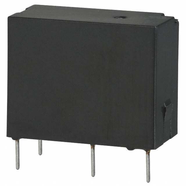
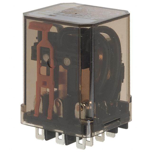
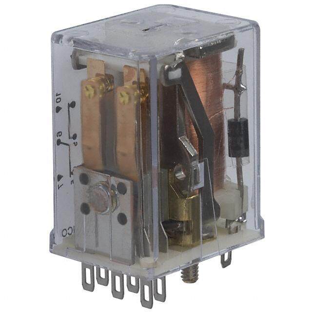
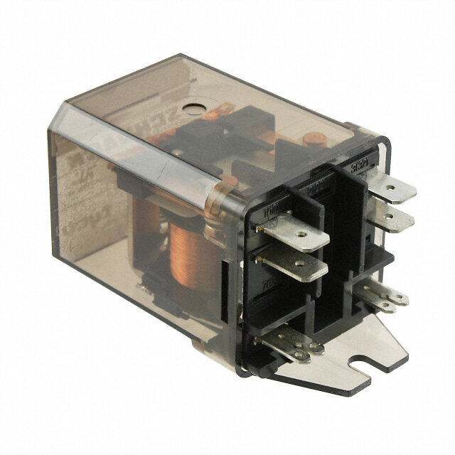
ICGOO电子元器件商城为您提供DK1A-3V-F由Panasonic Corporation设计生产,在icgoo商城现货销售,并且可以通过原厂、代理商等渠道进行代购。 DK1A-3V-F价格参考。Panasonic CorporationDK1A-3V-F封装/规格:功率继电器,高于 2 A, 通用 继电器 SPST-NO(1 Form A) 3VDC 线圈 通孔。您可以下载DK1A-3V-F参考资料、Datasheet数据手册功能说明书,资料中有DK1A-3V-F 详细功能的应用电路图电压和使用方法及教程。
Panasonic Electric Works的DK1A-3V-F是一款功率继电器,额定电流高于2A,广泛应用于需要高可靠性和稳定性的电路控制场合。该继电器适用于工业自动化设备,如PLC控制系统、机床控制、自动化生产线等,用于实现对高功率负载的开关控制。

此外,DK1A-3V-F也常见于家电控制电路中,例如空调、电热水器、洗衣机等大功率家用电器,用于控制压缩机、加热元件或风扇电机等部件的通断。其高耐压和强抗干扰能力,使其在恶劣电气环境中仍能稳定工作。

在能源管理系统中,该继电器可用于太阳能逆变器、储能系统或智能电表中,实现对电力设备的远程控制与保护。同时,它也适用于交通运输设备,如电动车辆的充电控制、车载空调系统等场景。

总之,DK1A-3V-F凭借其高可靠性、长寿命和较强的负载能力,广泛应用于工业、家电、能源及交通等多个领域,适用于需要稳定控制高功率负载的各类电子与电气设备中。
| 参数 | 数值 |
| 产品目录 | |
| 描述 | RELAY GEN PURPOSE SPST 10A 3V通用继电器 1 Form A, 3VDC 10A 250VAC 10A 30VDC |
| 产品分类 | |
| 品牌 | Panasonic Industrial Devices |
| 产品手册 | |
| 产品图片 |
|
| rohs | 符合RoHS无铅 / 符合限制有害物质指令(RoHS)规范要求 |
| 产品系列 | 通用继电器,Panasonic Industrial Devices DK1a-3V-FDK |
| mouser_ship_limit | 该产品可能需要其他文件才能进口到中国。 |
| 数据手册 | |
| 产品型号 | DK1a-3V-F |
| 产品目录绘图 |
|
| 产品目录页面 | |
| 产品种类 | 通用继电器 |
| 关闭电压(最小值) | 0.3 VDC |
| 其它名称 | 255-2057 |
| 其它有关文件 | |
| 功耗 | 200 mW |
| 包装 | 管件 |
| 商标 | Panasonic Industrial Devices |
| 安装类型 | 通孔 |
| 安装风格 | Through Hole |
| 导通电压(最大值) | 2.1 VDC |
| 封装 | Bulk |
| 工作时间 | 10ms |
| 工作温度 | -40°C ~ 65°C |
| 工厂包装数量 | 50 |
| 开关电压 | 250VAC,125VDC - 最小值 |
| 标准包装 | 50 |
| 特性 | 密封式 - 全部 |
| 相关产品 | /product-detail/zh/DK1A-PS/255-1101-ND/251873 |
| 端子类型 | PC 引脚 |
| 线圈功率 | 200 mW |
| 线圈电压 | 3 V |
| 线圈电流 | 66.6 mA |
| 线圈电阻 | 45 Ohms |
| 线圈端接 | Solder Pin |
| 线圈类型 | Non-Latching |
| 继电器类型 | 通用 |
| 触头外形 | SPST-NO(1 A 型) |
| 触头材料 | 银锡氧化物(AgSnO) |
| 触点形式 | SPST (1 Form A) |
| 触点材料 | Silver Tin Oxide |
| 触点端接 | Solder Terminal |
| 释放时间 | 8ms |
| 额定接触(电流) | 10A |


.jpg)

- 商务部:美国ITC正式对集成电路等产品启动337调查
- 曝三星4nm工艺存在良率问题 高通将骁龙8 Gen1或转产台积电
- 太阳诱电将投资9.5亿元在常州建新厂生产MLCC 预计2023年完工
- 英特尔发布欧洲新工厂建设计划 深化IDM 2.0 战略
- 台积电先进制程称霸业界 有大客户加持明年业绩稳了
- 达到5530亿美元!SIA预计今年全球半导体销售额将创下新高
- 英特尔拟将自动驾驶子公司Mobileye上市 估值或超500亿美元
- 三星加码芯片和SET,合并消费电子和移动部门,撤换高东真等 CEO
- 三星电子宣布重大人事变动 还合并消费电子和移动部门
- 海关总署:前11个月进口集成电路产品价值2.52万亿元 增长14.8%
PDF Datasheet 数据手册内容提取
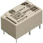
1a 10A, 1a1b/2a 8A small DK RELAYS polarized power relays FEATURES TYPICAL APPLICATIONS 1.Compact with high capacity 1.Switching power supply High capacity switching in a small 2.Power switching for various package: 1 Form A, 10 A 250 V AC; OA equipment 1 Form A 1 Form B and 2 Form A, 8 A 3.Control or driving relays for 250 V AC. industrial machines (robotics, 2.High sensitivity: 200 mW nominal numerical control machines, etc.) operating power 4.Output relays for programmable 3.High breakdown voltage logic controllers, temperature Independent coil and the contact controllers, timers and so on RoHS compliant structure improves breakdown voltage. 5.Home appliances Between contact Between open contacts and coil Protective construction: Sealed type 4,000 Vrms for 1 min. 1,000 Vrms for 1 min. 10,000 V surge 1,500 V surge breakdown voltage breakdown voltage Conforms with FCC Part 68 4.Latching types available 5.Sealed construction allows automatic washing 6.Sockets are available 7.Complies with safety standards Complies with Japan Electrical Appliance and Material Safety Law requirements for operating 200 V power supply circuits, and complies with UL, CSA, and TÜV safety standards. ORDERING INFORMATION DK Contact arrangement 1a: 1 Form A 2a: 2 Form A 1a1b:1 Form A 1 Form B Operating function Nil:Single side stable L2:2 coil latching Nominal coil voltage (DC) 3, 5, 6, 9, 12, 24V Contact material F: 1 Form A (Au-flashed AgSnO2 type) Nil:2 Form A, 1 FormA 1 Form B (Au-flashed AgNi type) Note: VDE approved type is available. –1– ASCTB177E 201702-T
DK TYPES Contact Nominal coil Single side stable 2 coil latching arrangement voltage Part No. Part No. 3V DC DK1a-3V-F DK1a-L2-3V-F 5V DC DK1a-5V-F DK1a-L2-5V-F 6V DC DK1a-6V-F DK1a-L2-6V-F 1 Form A 9V DC DK1a-9V-F DK1a-L2-9V-F 12V DC DK1a-12V-F DK1a-L2-12V-F 24V DC DK1a-24V-F DK1a-L2-24V-F 3V DC DK1a1b-3V DK1a1b-L2-3V 5V DC DK1a1b-5V DK1a1b-L2-5V 1 Form A 6V DC DK1a1b-6V DK1a1b-L2-6V 1 Form B 9V DC DK1a1b-9V DK1a1b-L2-9V 12V DC DK1a1b-12V DK1a1b-L2-12V 24V DC DK1a1b-24V DK1a1b-L2-24V 3V DC DK2a-3V DK2a-L2-3V 5V DC DK2a-5V DK2a-L2-5V 6V DC DK2a-6V DK2a-L2-6V 2 Form A 9V DC DK2a-9V DK2a-L2-9V 12V DC DK2a-12V DK2a-L2-12V 24V DC DK2a-24V DK2a-L2-24V Standard packing: Carton: 50 pcs.; Case: 500 pcs. * Sockets available. RATING 1. Coil data 1) Single side stable Nominal operating Nominal coil Pick-up voltage Drop-out voltage Coil resistance Nominal operating Max. applied voltage voltage (at 20°C 68°F) (at 20°C 68°F) [±10%] c(autr r2e0n°tC 68°F) [±10%] (at 20°C 68°F) power (at 20°C 68°F) 3V DC 66.6mA 45Ω 5V DC 40mA 125Ω 6V DC 70%V or less of 10%V or more of 33.3mA 180Ω 130%V of nominal voltage nominal voltage 200mW 9V DC (Initial) (Initial) 22.2mA 405Ω nominal voltage 12V DC 16.6mA 720Ω 24V DC 8.3mA 2,880Ω 2) 2 coil latching Nominal operating Coil resistance Nominal operating Novmoilntaagl ecoil (aSt e2t0 v°Col t6a8g°eF ) (Raet s2e0t° Cvo 6lt8a°gFe) [±10%] c(autr r2e0n°tC 68°F) [±10%] (at 20°C 68°F) power Ma(xa. ta 2p0p°liCe d6 8vo°Flt)age Set coil Reset coil Set coil Reset coil Set coil Reset coil 3V DC 66.6mA 66.6mA 45Ω 45Ω 5V DC 40mA 40mA 125Ω 125Ω 6V DC 70%V or less of 70%V or less of 33.3mA 33.3mA 180Ω 180Ω 130%V of nominal voltage nominal voltage 200mW 200mW 9V DC (Initial) (Initial) 22.2mA 22.2mA 405Ω 405Ω nominal voltage 12V DC 16.6mA 16.6mA 720Ω 720Ω 24V DC 8.3mA 8.3mA 2,880Ω 2,880Ω –2– ASCTB177E 201702-T
DK 2. Specifications Characteristics Item Specifications Arrangement 1 Form A 1 Form A 1 Form B 2 Form A Contact Contact resistance (Initial) Max. 30 mΩ (By voltage drop 6 V DC 1A) Contact material Au-flashed AgSnO2 type Au-flashed AgNi type Nominal switching capacity (resistive load) 10 A 250 V AC, 10 A 30 V DC 8 A 250 V AC,8 A 30 V DC 8 A 250 V AC,8 A 30 V DC Max. switching power (resistive load) 2,500VA, 300 W 2,000 VA, 240 W 2,000 VA, 240 W Rating Max. switching voltage 250 V AC, 125 V DC (0.2A) 250 V AC, 125 V DC (0.2A) 250 V AC, 125 V DC (0.2A) Max. switching current 10 A 8 A 8 A Min. switching capacity (Reference value)*1 10m A 5 V DC Insulation resistance (Initial) Min. 1,000MΩ (at 500V DC) Measurement at same location as “Breakdown voltage” section. Breakdown voltage Between open contacts 1,000 Vrms for 1min. (Detection current: 10mA.) (Initial) Between contact and coil 4,000 Vrms for 1min. (Detection current: 10mA.) Electrical Surge breakdown between contacts and coil 10,000 V characteristics voltage*2 (Initial) Operate time [Set time] (at 20°C 68°F) Max. 10 ms (Approx. 5 ms) [10 ms (Approx. 5 ms)] (Nominal coil voltage applied to the coil, excluding contact bounce time.) Release time [Reset time] (at 20°C 68°F) Max. 8 ms (Approx. 3 ms) [10 ms (Approx. 3 ms)] (Nominal coil voltage applied to the coil, excluding contact bounce time.) (without diode) Functional Min. 98 m/s2 (Half-wave pulse of sine wave: 11 ms; detection time: 10μs.) Shock resistance Mechanical Destructive Min. 980 m/s2 (Half-wave pulse of sine wave: 6 ms.) characteristics Functional 10 to 55 Hz at double amplitude of 1.5 mm (Detection time: 10μs.) Vibration resistance Destructive 10 to 55 Hz at double amplitude of 3 mm Expected life Mechanical Min. 5×10⁷ (at 300 times/min.) Ambient temperature: –40°C to +65°C –40°F to +149°F, Conditions Conditions for operation, transport and storage*3 Humidity: 5 to 85% R.H. (Not freezing and condensing at low temperature) Unit weight Approx. 5 g .18 oz Approx. 6 g .21 oz Approx. 6 g .21 oz Notes:*1.This value can change due to the switching frequency, environmental conditions, and desired reliability level, therefore it is recommended to check this with the actual load. *2.Wave is standard shock voltage of ±1.2×50μs according to JEC-212-1981 *3.The upper limit of the ambient temperature is the maximum temperature that can satisfy the coil temperature rise value. Refer to Usage, transport and storage conditions in NOTES. 3. Electrical life Condition: Resistive load, at 20 times/min. Type Switching capacity Number of operations 1 Form A 10A 250V AC Min. 1×10⁵ 10A 30V DC 1 Form A 1 Form B, 2 Form A 8A 250V AC Min. 1×10⁵ 8A 30V DC REFERENCE DATA 1-(1). Maximum operating power (1 Form A) 1-(2). Maximum operating power 2-(1). Life curve (1 Form A) (1 Form A 1 Form B, 2 Form A) 100 100 1,000 A A ntact current, 105 DACC i nin d(ducuocctsitvϕive=e l 0olo.a4ad)d AC resistive load ntact current, 105 AC in d(ucoctsivϕe= l0o.a4d) AC resistive load ×4Life, 10100 23500 V V D ACC r eresissitsivtieve lo loaadd Co (L/R = 7 ms) Co DC inductive load 1 1 (L/R = 7 ms) 10 250 V AC inductive load (cosϕ= 0.4) DC resistive load DC resistive load 30 V DC inductive load (L/R = 7 ms) 0.1 0.1 1 10 100 1,000 10 100 1,000 0 1 2 3 4 5 6 7 8 9 10 Contact voltage, V Contact voltage, V Contact current, A –3– ASCTB177E 201702-T
DK 2-(2). Life curve 3-(1). Operate/Release time (1 Form A) 3-(2). Operate/Release time (1 Form A 1 Form B, 2 Form A) Tested sample: DK1a-24V, 5 pcs. (1 Form A 1 Form B, 2 Form A) Tested sample: DK1a1b-12V, 5 pcs. 1,000 9 9 8 8 Release time ms 7 Operate time ms 7 (with diode) Max. e, e, x ×410100 ase tim 56 MMxaaxx.. ase tim 56 Min. Life, 10 23500 V V D ACC inindduuccttiviv23ee50 l0 olVo aVa dDd AC ((LCc /ro Rerses ϕ=iss i=ts7i vt 0imev.e4 slo ))loaadd Operate/rele 234 R(weitleha dsieo dtiem)e MMxMxaiinnx... Operate/rele 234 Operate Rtiemleease time MMMMxxaaiinnxx.... Min. 1 1 Release time 10 1 2 3 4 5 6 7 8 9 10 0 80 90 10 110 120 130 140 0 80 90 10 110 120 130 140 Contact current, A Coil applied voltage,%V Coil applied voltage,%V 4-(1). Coil temperature rise (1 Form A) 4-(2). Coil temperature rise 5-(1). Ambient temperature characteristics Tested sample: DK1a-12V, 5 pcs. (1 Form A 1 Form B, 2 Form A) (1 Form A) Ambient temperature: 30°C 86°F Tested sample: DK1a1b-12V, 5 pcs. Tested sample: DK1a-24V, 6 pcs Ambient temperature: 20°C 68°F Ambient temperature: –40°C to +80°C –40°F to +176°F 130 % o, °Coil temperature rise, C 54320000 17500AAAA °Coil temperature rise, C 23450000 850 AAA -40 -20 0Variation rati1119012000020 Ate4mDvm0obrplotieeaprng-aote6tPvuu0otircletka, -g°uCep80 10 10 80 0 0 70 80 90 100 110 120 130 80 90 100 110 120 130 Coil applied voltage,%V Coil applied voltage,%V 5-(2). Ambient temperature characteristics (1 Form A 1 Form B, 2 Form A) atio, % 130 Pvoicltka-guep on r 120 ati ari 110 V –40 –20 0100 40 60 80 20 Ambient temperature,°C 90 Drop-out 80 voltage 70 –4– ASCTB177E 201702-T
DK DIMENSIONS (mm inch) The CAD data of the products with a CAD Data mark can be downloaded from: http://industrial.panasonic.com/ac/e/ 1. 1 Form A type External dimensions PC board pattern (Bottom view) Schematic CAD Data Single side stable type Single side stable type (Bottom view) .72807 .1429.25 22--0.0.93 5d idai.a. 1.04.0106 7.3.6020 22-.-014.13 ddiiaa.. Single side stable type 1 3 4 - 9.7 .382 10.16 + .400 6 .001.23 0.4 0.8 0.8 .133.58 0.0.416 (Deenergized condition) .016 .031 .031 1.2 10.16 7.62 1.11 .047 10.16 .400 .300 .044 .400 2 coil latching type 2 coil latching type 2 coil latching type .72807 .1429.25 33--0.0.93 5d idai.a. 1.04.0106 7.3.6020 22-.-014.13 ddiiaa.. 1 3 4 - + + 9.7 .382 10.16 6 5 .400 .001.23 0.4 0.5 0.8 0.8 .133.85 .00.146 (Reset condition) .016 .020 .031 .031 1.2 2.54 7.62 7.62 1.11 .047 10.16 Since this is a polarized relay, .100 .300 .300 .044 .400 the connection to the coil should be done according to General tolerance: ±0.3 ±.012 Tolerance: ±0.1 ±.004 the above schematic. 2. 1 Form A 1 Form B type, 2 Form A type CAD Data External dimensions PC board pattern (Bottom view) Schematic Single side stable type Single side stable type (Bottom view) .72807 .51951 22--0.0.93 5d idai.a. 1.04.0106 7.3.6020 44-.-014.31 ddiiaa.. <1S Finogrmle sAi d1e F sotarmbl eB t ytyppee> 9.7 1 3 4 .382 - 10.16 .400 3.5 ..00001..14362 10..10063.81 7.62 0.01.83.111 .1328.42 10.16 0.0.416 +8 6 5 .400 .300 .044 .095 .400 (Deenergized condition) 2 coil latching type 2 coil latching type 2 coil latching type 1 3 4 .72807 .51951 33--0.0.93 5d idai.a. 1.04.0106 7.3.6020 44-.-014.31 ddiiaa.. - + + 9.7 .382 8 7 6 5 0.3 10.16 .012 3.5 .400 (Reset condition) .00.146 0.0.416 .00.381 .00.381 .138 0.4 <2 Form A> 2.54 7.62 7.62 1.11 2.42 10.16 .016 Single side stable type .100 .300 .300 .044 .095 .400 1 3 4 - General tolerance: ±0.3 ±.012 Tolerance: ±0.1 ±.004 + 8 6 5 (Deenergized condition) 2 coil latching type 1 3 4 - + + 8 7 6 5 (Reset condition) Since this is a polarized relay, the connection to the coil should be done according to the above schematic. –5– ASCTB177E 201702-T
DK SAFETY STANDARDS UL/C-UL (Recognized) CSA (Certified) TÜV (Certified) Type File No. Rating File No. Rating File No. Rating 10A 250V AC 10A 250V AC 10A 250V AC (cosφ=1.0) B 12 06 1 Form A E43028 10A 30V DC LR26550 10A 30V DC 10A 30V DC (0ms) 13461 329 1/3HP 125, 250V AC 1/3HP 125, 250V AC 5A 250V AC (cosφ=0.4) 8A 250V AC 8A 250V AC 8A 250V AC (cosφ=1.0) 1 Form A 1 Form B, B 12 06 E43028 8A 30V DC LR26550 8A 30V DC 8A 30V DC (0ms) 2 Form A 13461 329 1/4HP 125, 250V AC 1/4HP 125, 250V AC 4A 250V AC (cosφ=0.4) Notes:VDE approved type is available. Please contact our company. INSULATION CHARACTERISTICS (IEC61810-1) Item Characteristics Clearance/Creepage distance (IEC61810-1) Min. 5.5/5.5mm Category of protection (IEC61810-1) RT III Tracking resistance (IEC60112) PTI 175 Insulation material group III a Over voltage category III Rated voltage 250V Pollution degree 2 Type of insulation (Between contact and coil) Reinforced insulation Type of insulation (Between open contacts) Micro disconnection Notes:1.EN/IEC VDE Certified. 2.VDE approved type only. NOTES 1. For cautions for use, please read 3. External magnetic field 4. When using, please be aware that “GENERAL APPLICATION Since DK relays are highly sensitive the a contact and b contact sides of GUIDELINES”. polarized relays, their characteristics will 1 Form A 1 Form B type may go on 2. Soldering should be done under the be affected by a strong external magnetic simultaneously at operate time and following conditions: field. Avoid using the relay under that release time. 1) Preheating: Within 120°C 248°F and condition. within 120 seconds 2) Soldering iron: 260°C±5°C 500°F±41°F and within 6 seconds –6– ASCTB177E 201702-T
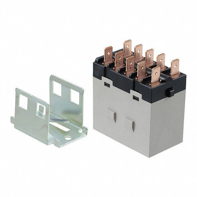
DK RELAY ACCESSORIES PC BOARD SOCKETS TYPES Type Part No. Single side stable DK1a-PS 1 Form A 2 coil latching DK1a-PSL2 1 Form A 1 Form B, Single side stable DK2a-PS 2 Form A 2 coil latching DK2a-PSL2 Standard packing: Carton: 50 pcs.; Case: 500 pcs RoHS compliant RELAY COMPATIBILITY SPECIFICATIONS Socket 1 Form A 1 Form A 1 Form B, 2 Form A Item Specifications Single side 2 coil Single side 2 coil 4,000 Vrms Relay stable type latching type stable type latching type Breakdown (Detection current: 10 mA) Single side stable type (cid:2) (cid:2) — — voltage (Initial) (Except the portion between 1 Form A coil terminals) 2 coil latching type — (cid:2) — — 1 Form A 1 Form B, Single side stable type — — (cid:2) (cid:2) Irnessuisltaatniocne (Initial) Min. 1,000 mΩ (at 500 V DC) 2 Form A 2 coil latching type — — — (cid:2) Heat resistance 150°C (for 1 hour) Max. continuous 10 A (DK1a-PS, DK1a-PSL2), current 8 A (DK2a-PS, DK2a-PSL2) DIMENSIONS (mm inch) The CAD data of the products with a CAD Data mark can be downloaded from: http://industrial.panasonic.com/ac/e/ CAD Data External dimensions PC board pattern (Bottom view) 1 Form A 1 Form A 1 Form B, 2 Form A 15±0.6 .591±.024 1.2 dia. 1.2 dia. 1 2 3 4 .047 dia. 1 2 3 4 .047 dia. 23±0.6 .906±.024 6 5 8 7 6 5 2.54 2.54 .100 .100 .51339.7±±.002.64 .61679±±0.0.624 2.1.5040 2.1.5040 6±0.3 .236±.012 Tolerance: ±0.1 ±.004 ..012010..52304±±±±.0.000.010.144 .370.602±±.001.32.37.00.0630.218±±.001.32 .133.44±±.00.132 .1400..0010.±612.±05001.23 Note:NThoe.2 a abnodv 5e tsehromwinsa 2l acroei le llaimtcihniantge dty opne .s ingle Note:NThoe.2 a abnodv 7e tsehromwinsa 2l acroei le llaimtcihniantge dty opne .s ingle side stable type. side stable type. General tolerance: ±0.3 ±.012 FIXING AND REMOVAL METHOD 1. Match the direction of relay and socket. 3. Remove the relay, applying force in the 4. In case there is not enough space to direction shown below. grasp relay with fingers, use screwdrivers in the way shown below. 2. Both ends of the relay are to be secured firmly so that the socket hooks on the top surface of the relay. Notes:1.Exercise care when removing relays. If greater than necessary force is applied at the socket hooks, deformation may alter the dimensions so that the hook will no longer catch, and other damage may also occur. GOOD NO GOOD 2.It is hazardous to use IC chip sockets. –1– ASCTB265E 201702-T
None
Mouser Electronics Authorized Distributor Click to View Pricing, Inventory, Delivery & Lifecycle Information: P anasonic: DK1A-12V-F DK1A-24V-F DK1A1B-L-3V DK1A1B-L2-5V DK1A1B-5V DK2A-5V DK1A1B-6V DK1A1B-12V DK1A1B-24V DK2A-24V DK1A-L2-12V DK1A-L2-24V DK2A-PS DK2A-12V DK2A-L2-12V DK1A1B-L2-12V DK1A- L2-12V-F DK1A-PS DK2A-L2-5V DK1A-5V-F DK1A-L2-24V-F DK1a1b-3V DK1a1b-9V DK1a1b-L2-24V DK1a1b- L2-3V DK1a1b-L2-6V DK1a1b-L2-9V DK1a-3V-F DK1a-6V-F DK1a-9V-F DK1a-L2-3V-F DK1a-L2-5V-F DK1a-L2- 9V-F DK2a-6V DK2a-L2-24V DK2a-L2-3V DK2a-L2-6V DK1A1B-L-5V DK1A-3V DK1A-6V DK1A-9V DK1A-B-24V DK1A-B-24V-F DK1A-L-12V DK1A-L-12V-F DK1A-L-24V DK1A-L2-6V DK1A-L2-9V DK1A-L-3V DK1A-L-5V DK1A-L-6V DK1A-L-9V DK1A-PSL2 DK2A-PSL2 DK2a-3V DK2a-9V