ICGOO在线商城 > DJT16F13-35JC-LC

 Datasheet下载
- 型号: DJT16F13-35JC-LC
- 制造商: CORCOM/TYCO ELECTRONICS
- 库位|库存: xxxx|xxxx
- 要求:
| 数量阶梯 | 香港交货 | 国内含税 |
| +xxxx | $xxxx | ¥xxxx |
查看当月历史价格
查看今年历史价格
DJT16F13-35JC-LC产品简介:
ICGOO电子元器件商城为您提供DJT16F13-35JC-LC由CORCOM/TYCO ELECTRONICS设计生产,在icgoo商城现货销售,并且可以通过原厂、代理商等渠道进行代购。 提供DJT16F13-35JC-LC价格参考以及CORCOM/TYCO ELECTRONICSDJT16F13-35JC-LC封装/规格参数等产品信息。 你可以下载DJT16F13-35JC-LC参考资料、Datasheet数据手册功能说明书, 资料中有DJT16F13-35JC-LC详细功能的应用电路图电压和使用方法及教程。
| 参数 | 数值 |
| 产品目录 | |
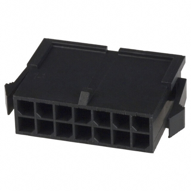
| 描述 | CONN HSG PLUG STRGHT 22POS SKT |
| 产品分类 | |
| 品牌 | TE Connectivity |
| 数据手册 | |
| 产品图片 | |
| 产品型号 | DJT16F13-35JC-LC |
| rohs | 含铅 / 不符合限制有害物质指令(RoHS)规范要求 |
| 产品系列 | MIL-C-38999 系列 I, DJT |
| 侵入防护 | 抗环境影响 |
| 其它名称 | DDJT16F13-35JC-LC |
| 包装 | 散装 |
| 备注 | 不提供触点 |
| 外壳尺寸-插件 | 13-35 |
| 外壳尺寸,MIL | - |
| 外壳材料,镀层 | 铝,镀镍 |
| 安装类型 | 自由悬挂 |
| 朝向 | C |
| 标准包装 | 1 |
| 特性 | 屏蔽 |
| 紧固类型 | 插销锁 |
| 触头尺寸 | 22D |
| 触头类型 | 压接 |
| 连接器类型 | 母触点插头 |
| 配套产品 | /product-detail/zh/DJT10F13-35HC-LC/DDJT10F13-35HC-LC-ND/3414342/product-detail/zh/DJT10F13-35HC/DDJT10F13-35HC-ND/3414341 |
| 针脚数 | 22 |

.jpg)


- 商务部:美国ITC正式对集成电路等产品启动337调查
- 曝三星4nm工艺存在良率问题 高通将骁龙8 Gen1或转产台积电
- 太阳诱电将投资9.5亿元在常州建新厂生产MLCC 预计2023年完工
- 英特尔发布欧洲新工厂建设计划 深化IDM 2.0 战略
- 台积电先进制程称霸业界 有大客户加持明年业绩稳了
- 达到5530亿美元!SIA预计今年全球半导体销售额将创下新高
- 英特尔拟将自动驾驶子公司Mobileye上市 估值或超500亿美元
- 三星加码芯片和SET,合并消费电子和移动部门,撤换高东真等 CEO
- 三星电子宣布重大人事变动 还合并消费电子和移动部门
- 海关总署:前11个月进口集成电路产品价值2.52万亿元 增长14.8%


.jpg)


PDF Datasheet 数据手册内容提取
T TE Connectivity DEUTSCH DJT Series E C o MIL-DTL-38999 Series I Connectors n n E INTERMATEABLE WITH SOURIAU CONNECTORS C AND ALL MIL-DTL-38999 SERIES I T i v TE DEUTSCH DJT series MIL-DTL-38999 series I connectors i T offer high density contact arrangements in a miniature metal y circular connector. DJT connectors meet MIL-38999 and were D originally designed as military and aerospace components. The E TE DEUTSCH DJT series is now being used in many applications U requiring extremely reliable interconnections. These TE DEUTSCH T S connectors are quick-mating, environmentally-sealed, triple-lead C threaded, have a self-locking coupling, and are EMI-RFI-shielded. H A variety of D38999 backshells are available. For full product D details on the TE DEUTSCH DJT series MIL-DTL-38999 series I J connectors, please see the specifications below. T S E r i E APPLICATIOnS S • High-performance military aircraft M • Commercial aircraft i L - • Communications equipment D T • Armored personnel carriers & tanks L - • High temperature industrial equipment 3 8 9 • Missiles 9 9 • Shipboard S E r i E S i FEATURES C • High Reliability o • Outstanding EMI/RFI Shielding Protection n n • High Density E C • Self Locking Connector Systems T o • MIL-DTL-38999 r S • Scoop-Proof Contact Protection For assistance in Europe and China, please see the back cover for a complete listing of our branch offices and contact numbers. Specifications subject to change. 45
T TECHNICAL E MATERIALS AND FINISHES C SPECIFICATIONS O Shell Aluminium alloy N Bayonet Pins Passivated stainless steel per QQ-S-763 N E Shell Plating Electroless nickel and olive drab chromate over nickel C T I Contacts Copper alloy V I T Contact Platings 50u" gold plated Y D Insulator Rigid plastic dielectric E U Seals Fluorinated silicone based elastomer T S Grounding Springs Beryllium copper C H D ELECTRICAL DATA J T Wire Range Sizes 12-28AWG S E Insulation Resistance 5000 Megaohms minimum at 77ºF (25ºC) R I E Contact Resistance of mated contacts end to end S M CONTACT SIZE MAXIMUM MILLIVOLT DROP I L 22D 40 - D 20 35 T L 16 25 - 3 8 12 25 9 9 9 Test Voltage ac rms S E SERVICE SEA LEVEL 100,000 FEET ALTITUDE R RATING MATED UNMATED MATED UNMATED IE M 1300 1300 800 200 S N 1000 1000 600 200 I I 1800 1800 1000 200 C O II 2300 2300 1000 200 N N Opertaing Voltage E C SERVICE RATING T N M I II O Operating Voltage 300VAC/450VDC 400VAC/500VDC 600VAC/850VDC 900VAC/1250VDC R S Current Rating MAX. CURRENT FOR POTENTIAL DROP MILLIVOLT WIRE SIZE CONTACT SIZE TEST IN AMPS AT 77ºF (25ºC) 24 20 3 <45 20 20 7.5 <55 20 16 7.5 <45 16 16 13 <50 14 12 17 <45 12 12 23 <50 46 For assistance in North America: +1 800.642.8750 for Pricing/Delivery or +1 800.523.0727 Tech Support • www.peigenesis.com • sales@peigenesis.com
TECHnICAL T E MECHANICAL DATA SPECIFICATIOnS C Operating B - Olive Drab -65ºC to +175ºC (-85ºF to +347ºF) o Temperature F - Electroless nickel -65ºC to +200ºC (-85ºF to +392ºF) n n Sealing Against sand, dust per MIL-STD-202 & ice resistance E C Wire Sealing Range T i v MiniMuM MaxiMuM ContaCt Size iT inCheS MM inCheS MM y 22D 0.030 0.76 0.054 1.37 D 20 0.040 1.02 0.83 2.11 E 16 0.065 1.65 0.109 2.77 U 12 0.097 2.46 0.142 3.61 T 8 (Coax) 0.135 3.43 0.155 3.94 S 8 (twinax) 0.124 3.15 0.134 3.4 C H Insulation Strip Length D J Strip length T ContaCt Size inCheS MM S 22D 0.125 3.18 E r 20 0.188 4.77 i 16 0.188 4.77 E 12 0.188 4.77 S M Mating Life 500 mating cycle i L B - Olive Drab, 500 hours per MIL-STD-1344A method 1001 condition C - Salt Spray D F - Electroless nickel, 48 hours per MIL-STD-1344A method 1001 condition B T L B - Olive Drab -65ºC to +175ºC (-85ºF to +347ºF) Temp Durability - F - Electroless nickel -65ºC to +200ºC (-85ºF to +392ºF) 3 8 Lubricating oils, hydraulic fluids, coolants, deicing fluids per 9 Chemical Resistance 9 MIL-STD-1344A Method 1016 condition a-1 9 Sine Vibration 60g at -55°C per MIL-DTL-38999L 4.5.23.2.1 S E Random Vibration 49.5 grms at ambient temperatures r i E Shock 300 grms S i EMI Shielding 100 MHz to 10 GHz - minimum attenuation of 50dB C Effectiveness o Contact Type Crimp, fiber optic, coax, twinax, or printed circuit n n number of Circuits 2 to 128 E C Rear Insertion/Rear Extraction with simple plastic or high T Contact Insertion quality metal hand tools. o r Polarization Five keyways with optional master keyway rotations S (note insert and main keyways remain fixed) Approvals MIL-DTL-38999 Contact Retention retention axial loaD +/-10 Separation forCe MiniMuM ContaCt Size perCent (initial) neWtonS lbS. neWtonS ounCeS 22D 44 10 0.19 0.7 20 15 67 0.19 0.7 16 25 111 0.56 2 12 25 111 0.83 3 8 25 111 1.39 5 8 twinax 25 111 1.39 5 For assistance in Europe and China, please see the back cover for a complete listing of our branch offices and contact numbers. 47 Specifications subject to change.
T HOw TO ORDER DJT SERIES COnnECTORS - MILITAR y E C 1 2 3A 4 3B 5 6 7 o n n MS27468 T 25 F 35 P –LC E C SHELL STyLE CLASS SIzE PLATINg LAyOUT CONTACT POLARIzATION MODIFIER T (Military part number example) (oMit for norMal) i v i T STEP 1: SELECT SHELL STyLE, PLug OR RECEPTACLE y D E RECEPTACLES Mates with PLUgS U T S C H D J T S E r MS27466 MS27468 MS27467 i E Front mount with rear Jam nut with rear Plug S accessory threads accessory threads M i STEP 2: SELECT CLASS L - D T L T = no Rear Accessories P = Potting Ring & Cup - 3 8 Available with PC pins. Contact us for more details. 9 9 STEP 3: SELECT LA yOuT 9 S a See page 52 for listing by # of contacts E r nuMber rating total 22D 20 16 12 i 9-35 M 6 6 E 9-98 I 3 3 S 11-5 I 5 5 i 11-35 M 13 13 C 11-99 I 7 7 o 13-4 I 4 4 n 13-35 M 22 22 n 13-98 I 10 10 15-5 II 5 5 E 15-18 I 18 18 C 15-35 M 37 37 T 15-97 I 12 8 4 o 17-6 I 6 6 r 17-8 II 8 8 S 17-26 I 26 26 17-35 M 55 55 19-11 II 11 11 19-32 I 32 32 19-35 M 66 66 21-11 I 11 11 21-16 II 16 16 21-35 M 79 79 21-41 I 41 41 23-21 II 21 21 23-35 M 100 100 23-53 I 53 53 23-55 I 55 55 25-4 I 56 48 8 25-19 I 19 19 25-24 I 24 12 12 25-29 I 29 29 25-35 M 128 128 25-61 I 61 61 WHEN CHOOSING LAYOUT First Number = Step 3A – Shell Size, Second Number = 3B – Layout 48 For assistance in North America: +1 800.642.8750 for Pricing/Delivery or +1 800.523.0727 Tech Support • www.peigenesis.com • sales@peigenesis.com
HOw TO ORDER DJT SERIES COnnECTORS - MILITAR y T E STEP 4: SELECT PLATIng C o n n E C B = Olive Drab Chromate over Cadmium over Electroless nickel -65°C to 175°C (-85°F to 347°F) T i F = Electroless nickel -65°C to 200°C (-85°F to 392°F) v i T y D STEP 5: SELECT COnTACT E U T S C H P = Pin S = Socket D H = 1500 cycle Pin contacts J T J = 1500 cycle Socket contacts S Note: See Step 7 if you are not ordering contacts with part. E r A = Less Pin Contacts i E B = Less Socket Contact S May be used for special contact types (PC Pin, Thermocouple, Fiber optic). M STEP 6: SELECT POLARIzATIOn iL - D T L Omit for normal - Shell 3 A = next Most Popular Size n a b C D 8 B = Limited Availability 9 9 95 77 - - 113 9 C = Check for Availability 9 D = Check for Availability 11 95 81 67 123 109 S E 13 95 75 63 127 115 r i 15 95 74 61 129 116 E S 17 95 77 65 125 113 i C 19 95 77 65 125 113 o n 21 95 77 65 125 113 n 23 95 80 69 121 110 E C 25 95 80 69 121 110 T Mating face of receptacle o r S STEP 7: SELECT MODIFIER Omit for standard contacts –LC = less contacts, wire hole fillers and plastic insertion/extraction tool. (Purchase Order must state Less Contacts) Note: –LC is not marked on part For assistance in Europe and China, please see the back cover for a complete listing of our branch offices and contact numbers. 49 Specifications subject to change.
T HOw TO ORDER DJT SERIES COnnECTORS - COMMERCIAL E 1 2 3 4 5 6 C o n DJT14 E 25-35 P N –LC n E C SHELL STyLE PLATINg LAyOUT CONTACT POLARIzATION MODIFIER T (Commerical part number example) i v i T STEP 1: SELECT SHELL STyLE, PLug OR RECEPTACLE y D Mates with RECEPTACLES PLUgS E U T S C H D J T S E r DJT10 DJT14 DJT16 iE Front mount with rear Jam nut with rear Plug + Most Popular S accessory threads accessory threads M iL STEP 2: SELECT PLATIng - D T L E = Olive Drab Chromate over Cadmium over Electroless nickel -65°C to 175°C (-85°F to 347°F) - 3 8 F = Electroless nickel -65°C to 200°C (-85°F to 392°F) 9 9 STEP 3: SELECT LA yOuT 9 S a See page 52 for listing by # of contacts E r nuMber rating total 22D 20 16 12 i 9-35 M 6 6 E S 9-98 I 3 3 11-5 I 5 5 i 11-35 M 13 13 C 11-99 I 7 7 o 13-4 I 4 4 n 13-35 M 22 22 n 13-98 I 10 10 E 15-5 II 5 5 C 15-18 I 18 18 T 15-35 M 37 37 o 15-97 I 12 8 4 r 17-6 I 6 6 S 17-8 II 8 8 17-26 I 26 26 17-35 M 55 55 19-11 II 11 11 19-32 I 32 32 19-35 M 66 66 21-11 I 11 11 21-16 II 16 16 21-35 M 79 79 21-41 I 41 41 23-21 II 21 21 23-35 M 100 100 23-53 I 53 53 23-55 I 55 55 25-4 I 56 48 8 25-19 I 19 19 25-24 I 24 12 12 25-29 I 29 29 25-35 M 128 128 25-61 I 61 61 50 For assistance in North America: +1 800.642.8750 for Pricing/Delivery or +1 800.523.0727 Tech Support • www.peigenesis.com • sales@peigenesis.com
HOw TO ORDER DJT SERIES COnnECTORS - COMMERCIAL T E C STEP 4: SELECT COnTACT o n n E C P = Pin T i S = Socket v H = 1500 cycle Pin contacts iT J = 1500 cycle Socket contacts y Note: See Step 7 if you are not ordering contacts with part. D E A = Less Pin Contacts U B = Less Socket Contact T May be used for special contact types (PC Pin, Thermocouple, Fiber optic). S C H D STEP 5: SELECT POLARIzATIOn J T S E r N = normal Standard Shell i A = next Most Popular Size n a b C D E B = Limited Availability S C = Check for Availability 9 95 77 - - 113 M D = Check for Availability i 11 95 81 67 123 109 L - D 13 95 75 63 127 115 T L 15 95 74 61 129 116 - 3 17 95 77 65 125 113 8 9 19 95 77 65 125 113 9 9 21 95 77 65 125 113 S E 23 95 80 69 121 110 r i 25 95 80 69 121 110 E S Mating Face of Receptacle i C o n STEP 6: SELECT MODIFIER n E C T o For other commercial modification, i.e., less tools, with PC contact or with endbell, contact us. r S Omit for standard contacts –LC = less contacts, wire hole fillers and plastic insertion/extraction tool. (Purchase Order must state Less Contacts) Note: LC is not marked on part For assistance in Europe and China, please see the back cover for a complete listing of our branch offices and contact numbers. 51 Specifications subject to change.
T LAyOuTS By nuMBER OF COnTACTS E C =22 =20 =16 =12 =8 o n n E C T i v iT layout 09-35 09-98 11-05 11-35 11-99 13-04 13-35 y # of ContaCtS 6 - #22 3 - #20 5 - #20 13 - #22 7 - #20 4 -#16 22 - #22 D ServiCe rating M i i M i i M E U T S C H D J T S E r layout 13-98 15-05 15-18 15-35 15-97* 17-06 17-08* i E S # of ContaCtS 10 - #20 5 - #16 18 - #20 37 - #22 8 - #20, 4 - #16 6 - #12 8 - #16 M ServiCe rating i ii i M i i ii i L - D T L - 3 8 9 9 9 S E r layout 17-26 17-35 19-11* 19-32 19-35 21-11* 21-16 i E # of ContaCtS 26 - #20 55 - #22 11 - #16 32 - #20 66 - #22 11 - #12 16 - #16 S ServiCe rating i M ii i M i ii i C o n n E C T o r S layout 21-41 21-35 23-21* 23-35* 23-53 23-55* # of ContaCtS 41 - #20 79 - #22 21 - #16 100 - #22 53 - #20 55 - #20 ServiCe rating i M ii M i i layout 25-04* 25-19* 25-24* 25-29* 25-35 25-61* # of ContaCtS 48 - #20, 8 - #16 19 - #12 12 - #16, 12 - #12 29 - #16 128 - #22 61 - #20 ServiCe rating i i i i M i 52 For assistance in North America: +1 800.642.8750 for Pricing/Delivery or +1 800.523.0727 Tech Support • www.peigenesis.com • sales@peigenesis.com
COnTACTS T E PINS C o n n E C T i v layout 09-35 09-98 11-05 11-35 11-99 13-04 13-35 iT y # of ContaCtS 6 - #22 3 - #20 5 - #20 13 - #22 7 - #20 4 -#16 22 - #22 D ServiCe rating M i i M i i M E U Insert head first, trim excess T S Wire Color banDS Wire Strip Wire inSulation Sealing Wire hole C ContaCt CriMp pin part lengthS range Wire hole filler H Size rSainzge e nuMber 1 2 3 in. MM Minin. . MMiMn. Minax.. MMaMx. filler Color D J 22D 28,26,24,22 M39029/58-360 orange blue black 0.125 3.18 0.030 0.760 0.054 1.37 MS27488-22-2 black T S 20 24,22,20 M39029/58-363 orange blue orange 0.188 4.77 0.040 1.020 0.083 2.11 MS27488-20-2 red E r layout 13-98 15-05 15-18 15-35 15-97* 17-06 17-08* 16 20,18,16 M39029/58-364 orange blue yellow 0.188 4.77 0.065 1.65 0.109 2.77 MS27488-16-2 blue i E # of ContaCtS 10 - #20 5 - #16 18 - #20 37 - #22 8 - #20, 4 - #16 6 - #12 8 - #16 12 14,12 M39029/58-365 orange blue green 0.188 4.77 0.097 2.46 0.142 3.61 MS27488-12-2 yellow S ServiCe rating i ii i M i i ii M i L - D T L - SOCkETS 3 8 9 9 9 S E layout 17-26 17-35 19-11* 19-32 19-35 21-11* 21-16 r i # of ContaCtS 26 - #20 55 - #22 11 - #16 32 - #20 66 - #22 11 - #12 16 - #16 E S ServiCe rating i M ii i M i ii i C o n Insert head first, trim excess n ContaCt CWriirMep SoCket part Color banDS Wlierneg StthrSip Wire inSurlaantigoen Sealing Wire hole Wire hole EC Size Size nuMber Min. Min. Max. Max. filler filler T range 1 2 3 in. MM in. MM in. MM Color o r 22D 28,26,24,22 M39029/56-348 orange yellow gray 0.125 3.18 0.030 0.760 0.054 1.37 MS27488-22-2 black S layout 21-41 21-35 23-21* 23-35* 23-53 23-55* 20 24,22,20 M39029/56-351 orange green brown 0.188 4.77 0.040 1.020 0.083 2.11 MS27488-20-2 red # of ContaCtS 41 - #20 79 - #22 21 - #16 100 - #22 53 - #20 55 - #20 16 20,18,16 M39029/56-352 orange green red 0.188 4.77 0.065 1.65 0.109 2.77 MS27488-16-2 blue ServiCe rating i M ii M i i 12 14,12 M39029/56-353 orange green orange 0.188 4.77 0.097 2.46 0.142 3.61 MS27488-12-2 yellow layout 25-04* 25-19* 25-24* 25-29* 25-35 25-61* # of ContaCtS 48 - #20, 8 - #16 19 - #12 12 - #16, 12 - #12 29 - #16 128 - #22 61 - #20 ServiCe rating i i i i M i For assistance in Europe and China, please see the back cover for a complete listing of our branch offices and contact numbers. 53 Specifications subject to change.
T COnTACT TOOLS E C PINS o n n E C T i v i T y D E U T S turret Metal plaStiC hanD turret poWer poWer C ContaCt heaD CriMp heaD CriMp tool inSertion/ H Size tool (loCator) (loCator) tool loCator inSertion extraCtion extraCtion inSertion extraCtion Color tool tool tip Color tip Color D tool J 22D M22520/2-01 M22520/2-09 - Wa22 M22520/2-09 MS27495a22M MS27495a22M M81969/14-01 green White T S 20 M22520/1-01 M22520/1-04 red Wa27f M22520/1-04 MS27495a20 MS27495a20 M81969/14-10 red orange E r 16 M22520/1-01 M22520/1-04 blue Wa27f M22520/1-04 MS27495a16 MS27495a16 M81969/14-03 blue White i E 12 M22520/1-01 M22520/1-04 yellow Wa27f M22520/1-04 Dak95-12b Drk95-12b M81969/14-04 yellow White S M i L - D T L SOCkETS - 3 8 9 9 9 S E r i E S i C o n turret Metal plaStiC hanD turret poWer poWer n ContaCt CriMp heaD heaD CriMp tool inSertion/ E Size tool (loCator) (loCator) tool loCator inSertion extraCtion extraCtion inSertion extraCtion C Color tool tool tool tip Color tip Color T o 22D M22520/2-01 M22520/2-09 - Wa22 M22520/2-09 MS27495a22M MS27495a22M M81969/14-01 green White r 20 M22520/1-01 M22520/1-04 red Wa27f M22520/1-04 MS27495a20 MS27495a20 M81969/14-10 red orange S 16 M22520/1-01 M22520/1-04 blue Wa27f M22520/1-04 MS27495a16 MS27495a16 M81969/14-03 blue White 12 M22520/1-01 M22520/1-04 yellow Wa27f M22520/1-04 Dak95-12b Drk95-12b M81969/14-04 yellow White 54 For assistance in North America: +1 800.642.8750 for Pricing/Delivery or +1 800.523.0727 Tech Support • www.peigenesis.com • sales@peigenesis.com
1.263 MAX J H MAX MASETøER POLARIZING KEYWAY PANE.1L 2T5H MICAKXNESS .I0N6S0E RMTA X MOUNTING HOLE PROTRUSION Fø Gø TYP. 4 PLACES (TYP) B Cø (TYP) RECOMMENDED PANEL CUTOUT B D ACCESSORY (TYP.) THREAD A (TYP.) BLUE GLANDS DIMEnSIOnS T E PLUgS C o MS27467/ DJT16 n 1.234 MAX n .241 MIN E C MASTER POLARIZING KEY .060 MAX INSERT T PROTRUSION i v A MAX O i OVER T KNURL y B D ACCESSORY THREAD R.F.I. SPRING E (REF) BLUE BAND U T S Shell Size a Dia. +/-.020 (+/- 0.51) b threaD unef-2a C 9 0.859 (21.81) 0.4375-28 H 11 0.984 (24.99) 0.5625-24 13 1.156 (29.36) 0.6875-24 D 15 1.281 (32.53) 0.8125-20 J 17 1.406 (35.71) 0.9375-20 T 19 1.516 (38.50) 1.0625-18 S E 21 1.641 (41.68) 1.1875-18 r 23 1.766 (44.85) 1.3125-18 i 25 1.891 (48.03) 1.4375-18 E S M FLANgE MOUNT i L MS27466/ DJT10 - D T L - 3 1.263 MAX 8 9 J H MAX MASETøER POLARIZING KEYWAY PANE.1L 2T5H MICAKXNESS .I0N6S0E RMTA X 99 MOUNTING HOLE PROTRUSION Fø Gø TYP. 4 PLACES S (TYP) E r B Cø i (TYP) E S RECOMMENDED PANEL CUTOUT B D ACCESSORY i (TYP.) THREAD C A o (TYP.) BLUE GLANDS n n E C T o C Dia. e Dia. g Dia. Shell Size a +/- .020 b +/- .005 +/- .003 D threaD +.010/-.005 f Dia. Min. +/- .005 h Max. J +.000/ -.005 r (+/- .508) (+/- .127) unef-2a (+ 0 / -.127) (+/- .076) (+ .254/ -.127) (+/- .127) S 9 0.938 (23.82) 0.719 (18.26) 0.570 (14.47) 0.4375-28 0.128 (3.25) 0.516 (13.10) 0.128 (3.25) .100 (2.54) 0.632 (16.05) 11 1.031 (26.18) 0.812 (20.62) 0.698 (17.72) 0.5625-24 0.128 (3.25) 0.664 (16.86) 0.128 (3.25) .100 (2.54) 0.632 (16.05) 13 1.125 (28.57) 0.906 (23.01) 0.848 (21.53) 0.6875-24 0.128 (3.25) 0.750 (19.05) 0.128 (3.25) .100 (2.54) 0.632 (16.05) 15 1.219 (30.96) 0.969 (24.61) 0.973 (24.71) 0.8125-20 0.128 (3.25) 0.906 (23.01) 0.128 (3.25) .100 (2.54) 0.632 (16.05) 17 1.312 (33.32) 1.062 (26.97) 1.098 (27.88) 0.9375-20 0.128 (3.25) 1.016 (25.80) 0.128 (3.25) .100 (2.54) 0.632 (16.05) 19 1.438 (36.52) 1.156 (29.36) 1.205 (30.60) 1.0612.253-41 M8AX 0.128 (3.25) 1.141 (28.98) 0.128 (3.25) .100 (2.54) 0.632 (16.05) .241 21 1.562 (39.67) 1.250 (31.75) 1.330 (33.78) 1.1875-18 0.M1I2N8 (3.25) 1.266 (32.15) 0.128 (3.25) .130 (3.30) 0.602 (15.29) 23MASTER PO1L.A6R8IZ8IN G(4 K2E.Y87) 1.375 (34.92) 1.455 (36.95) 1.3125-18 0.147 (3.73) 1.377 (34.97) 1.54 (39.11) .130 (3.30) 0.602 (15.29) .060 MAX INSERT 25 1.812 (46.02) 1.500 (38.10) 1.580 (40.13) 1.4375-18 0.147 (3.73)PROT1R.4U8SI4O N (37.69) 1.54 (39.11) .130 (3.30) 0.602 (15.29) A MAX O OVER KNURL All dimensions in inches (millimeters in parenthesis) B ACCESSORY THREAD R.F.I. SPRING (REF) BLUE BAND For assistance in Europe and China, please see the back cover for a complete listing of our branch offices and contact numbers. 55 Specifications subject to change.
T DIMEnSIOnS E C JAM NUT RECEPTACLE o n MS27484/ DJT14 n E C 1.225 MAX. T O-RING iv MASTER POLARIZINøGA KEYWAY PANEL NUT .I0N6S0E RMTA XP.ROTRUSION i T y D E U B FLAT øG F T S C H D THREAD D E THREADS J BLUE BANDS & T BAYONET HEADS S E a Dia. +/-.016 b flat + .000/- .010 f + .000/- .010 g Dia. + .000/- .010 r Shell Size (+/- .406) (+.000/-.254) D threaD unef -2a e threaD unef -2a (+.000/-.254) (+.000/-.254) i E 9 1.188 (30.18) 0.655 (16.64) 0.4375-28 0.6875-24 0.670 (17.02) 0.700 (17.78) S 11 1.375 (34.93) 0.755 (19.18) 0.5625.24 0.8125-20 0.771 (19.58) 0.825 (20.96) M 13 1.500 (38.10) 0.942 (23.93) 0.6875-24 1.000-20 0.955 (24.26) 1.010 (25.65) i L 15 1.625 (41.28) 1.066 (27.08) 0.8125-20 1.1250-18 1.085 (27.60) 1.135 (28.83) - D 17 1.750 (44.45) 1.191 (30.25) 0.9375-20 1.2500-18 1.210 (30.73) 1.260 (32.00) T L 19 1.938 (49.23) 1.316 (33.43) 1.0625-18 1.3750-18 1.335 (33.91) 1.385 (35.18) - 3 21 2.062 (52.37) 1.441 (36.60) 1.1875-18 1.5000-18 1.460 (37.08) 1.510 (38.35) 8 9 23 2.188 (55.58) 1.566 (39.78) 1.3125-18 1.6250-18 1.585 (40.26) 1.635 (41.53) 9 9 25 2.312 (58.72) 1.691 (42.95) 1.4375-18 1.7500-18 1.710 (43.43) 1.760 (44.70) S All dimensions in inches (millimeters in parenthesis) E r i E S i C o n n E C T o r S 56 For assistance in North America: +1 800.642.8750 for Pricing/Delivery or +1 800.523.0727 Tech Support • www.peigenesis.com • sales@peigenesis.com
ACCESSORIES T E C DUMMy RECEPTACLES, DUST CAPS & PLUg CAPS o n n E C T i v i T y D reCeptaCle DuSt CapS E DJt DuMMy reCeptaCleS plug DuSt Cap for flangeD for JaM nut U T 9 M38999/9-9b MS27502**9C MS27502**9n MS27501**9C S 11 M38999/9-11b MS27502**11C MS27502**11n MS27501**11C C H 13 M38999/9-13b MS27502**13C MS27502**13n MS27501**13C D 15 M38999/9-15b MS27502**15C MS27502**15n MS27501**15C J 17 M38999/9-17b MS27502**17C MS27502**17n MS27501**17C T S 19 M38999/9-19b MS27502**19C MS27502**19n MS27501**19C E 21 M38999/9-21b MS27502**21C MS27502**21n MS27501**21C r i 23 M38999/9-23b MS27502**23C MS27502**23n MS27501**23C E S 25 M38999/9-25b MS27502**25C MS27502**25n MS27501**25C M i ** Select Code for Plating L B = Olive Drab Chromate over Cadmium over nickel - D F = Electroless nickel T A = gold Iridite over Cadmium nickel L C = Hard Anodized -3 8 9 9 CABLE CLAMPS 9 S E r i E S i C o n n E C T Cable range o Straight right angle DJt Min Max r loW CoSt loW CoSt inCheS MM inCheS MM S 9 M85049/49-2-8** M85049/47**8 0.098 2.49 0.234 5.94 11 M85049/49-2-10** M85049/47**10 0.153 3.89 0.234 5.94 13 M85049/49-2-12** M85049/47**12 0.190 4.83 0.328 8.33 15 M85049/49-2-14** M85049/47**14 0.260 6.60 0.457 11.61 17 M85049/49-2-16** M85049/47**16 0.283 7.19 0.614 15.60 19 M85049/49-2-18** M85049/47**18 0.325 8.25 0.634 16.10 21 M85049/49-2-20** M85049/47**20 0.343 8.71 0.698 17.73 23 M85049/49-2-22** M85049/47**22 0.381 9.68 0.823 20.90 25 M85049/49-2-24** M85049/47**24 0.418 10.62 0.853 21.67 ** Select Code for Plating w = Olive Drab Chromate over Cadmium over nickel n = Electroless nickel A = Hard Anodized All dimensions in inches (millimeters in parenthesis) For assistance in Europe and China, please see the back cover for a complete listing of our branch offices and contact numbers. 57 Specifications subject to change.
T ACCESSORIES E C STANDARD MIL-SPEC o n n S = Straight E Mil-SpeC SealeD eMi/rfi a = 90 DegreeS enDbell type DeSCription C prefix b = 45 DegreeS T i v Designed for use with straight or right angle shrink boots. iT a knurled rear section with a boot groove provide an M85049/62 y y n S heat Shrink boot adapters excellent surface for the boot to grab the metal endbell. D available with lock wire and drain holes. aSee heat E Shrink boots on pages 168-169. U T S C non-environmental, designed for use with jacketed cable, H M85049/32 n n S extender backshell with cable clamp allows extra space to break out the wires and still provide D stain relief clamping to the outside of the cable jacket. J T S E r this eMi/rfi shielding environmentally sealing endbell i M85049/17 E y y S environmental Shielded endbell features a standard style cable clamp with gland seal at S the end of and extender style backshell. M i L - D T M85049/29 this eMi/rfi shielding non-environmentally sealing L n y S non-environmental Shielded endbell - endbell features a standard style cable clamp. 3 8 9 9 9 S banding adapters utilize a band of metal that fastens E and grounds cable shields to the outside of endbells. r this method of terminating shields has advantages in i E M85049/85 that they typically use tools to tighten trim the bands. S S M85049/86 these tools make the termination tight, repeatable, y y b banding adapter i M85049/87 reworkable (if you make a mistake just cut the band off C a and start again) and facilitates service. banding adapters o help lower the total applied cost by having simpler n designs that have fewer parts with uncomplicated n E assembly procedures. C T o r S M85049/27 n n S Compression nut Wire Seal Compression nut nOTE: If military-standard versions won’t work for your applications, please contact us with your requirements. 58 For assistance in North America: +1 800.642.8750 for Pricing/Delivery or +1 800.523.0727 Tech Support • www.peigenesis.com • sales@peigenesis.com
ASSEMBLy InSTRuCTIOnS T E C WIRE STRIPPINg o n Strip insulation from end of wire to be crimped. (See table Wire Size a n for proper stripping dimensions.) Do not cut or damage 22, 22M, 22D .125 (3.18) E wire strands. A 20 .188 (4.77) C 16 .188 (4.77) T 12 .188 (4.77) i v 10 .335 (8.51) i 8 (power) .470 (11.99) T y D E CONTACT CRIMPINg U T S correct crimp C H D J incorrect crimp T S E r i E S STEP 1: Strip wires. See above for correct strip STEP 2: M22520 series crimp tool and locator STEP 3: Insert contact and wire into tool jaws. M length for contact. Insert wire into rear of contact. is recommended. aSee page 54 for choice of tur- To crimp, squeeze handles together fully until i Wire insulation must push against rear of contact. ret head and selection setting according to correct ratchet releases and allows handles to expand; L Wire must be visible through inspection hole. size, part number and wire gauge size. otherwise, contact cannot be extracted from tool -D jaws. Maintain slight insertion pressure on wire T while crimping contact to wire.* L - 3 8 9 CONTACT INSERTION 9 9 S E r i E S i C o n n E C STEP 1: Remove hardware from plug or receptacle STEP 2: Using proper plastic or metal insertion tool for STEP 3: Press tool against contact shoulder T and slip over wire bundle in proper order for corresponding contact, position wire in tip of the tool and, with firm and even pressure, insert wired o reassembly. so that the tool tip presses against the contact shoulder. contact and tool tip into center contact cavity. r S STEP 4: When contact bottoms, a slight “click” can STEP 5: Remove tool and pull back lightly on wire STEP 6: After all contacts are inserted, fill any be heard as tines of metal retaining clip snap into to make sure contact is properly seated. Repeat empty cavities with wire sealing plugs. Reassemble place behind contact shoulder. operation with remainder of contacts to be inserted, plug or receptacle hardware. beginning with the center cavity and working outward in alternating rows. For assistance in Europe and China, please see the back cover for a complete listing of our branch offices and contact numbers. 59 Specifications subject to change.
T ASSEMBLy InSTRuCTIOnS E C o n n E C T i v i T y D E U T STEP 1: Remove hardware from plug or receptacle STEP 2: Using plastic or metal extraction tool with STEP 3: Insert tool into contact cavity until tool S and slide hardware back along wire bundle. proper color code corresponding to contact size, tip bottoms against the contact shoulder, expanding C place wire in tool. clip retaining tines. H D J T S E r i E S M i L - D T L - 3 STEP 4: Hold wire firmly in tool and extract wired STEP 5: Fill any empty cavities with wire sealing 8 contact and tool. Repeat operation for all contacts plugs. Reassemble plug or receptacle hardware. 9 9 to be extracted. 9 S E note: DTS series shown. r i E S i C o n n E C T o r S 60 For assistance in North America: +1 800.642.8750 for Pricing/Delivery or +1 800.523.0727 Tech Support • www.peigenesis.com • sales@peigenesis.com