ICGOO在线商城 > 连接器,互连器件 > 矩形连接器 - 阵列,边缘型,夹层式(板对板) > DF40C-90DS-0.4V(51)
.jpg)
 Datasheet下载
- 型号: DF40C-90DS-0.4V(51)
- 制造商: Hirose Electric
- 库位|库存: xxxx|xxxx
- 要求:
| 数量阶梯 | 香港交货 | 国内含税 |
| +xxxx | $xxxx | ¥xxxx |
查看当月历史价格
查看今年历史价格
DF40C-90DS-0.4V(51)产品简介:
ICGOO电子元器件商城为您提供DF40C-90DS-0.4V(51)由Hirose Electric设计生产,在icgoo商城现货销售,并且可以通过原厂、代理商等渠道进行代购。 DF40C-90DS-0.4V(51)价格参考。Hirose ElectricDF40C-90DS-0.4V(51)封装/规格:矩形连接器 - 阵列,边缘型,夹层式(板对板), 90 Position Connector Receptacle, Center Strip Contacts Surface Mount Gold。您可以下载DF40C-90DS-0.4V(51)参考资料、Datasheet数据手册功能说明书,资料中有DF40C-90DS-0.4V(51) 详细功能的应用电路图电压和使用方法及教程。
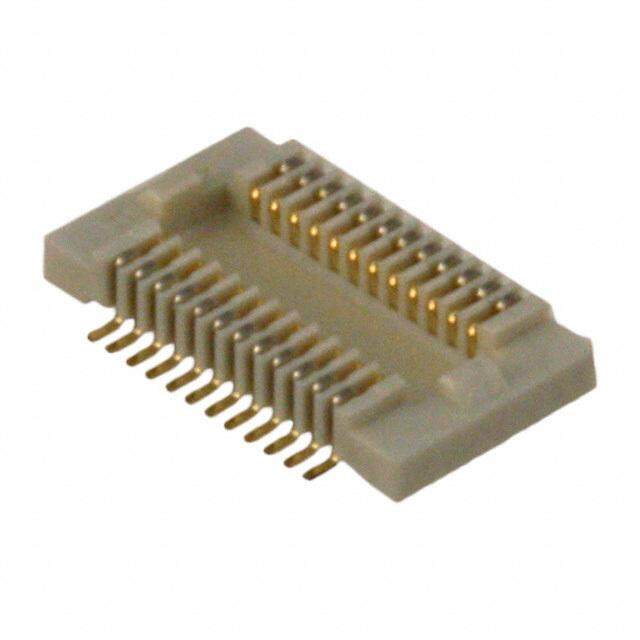
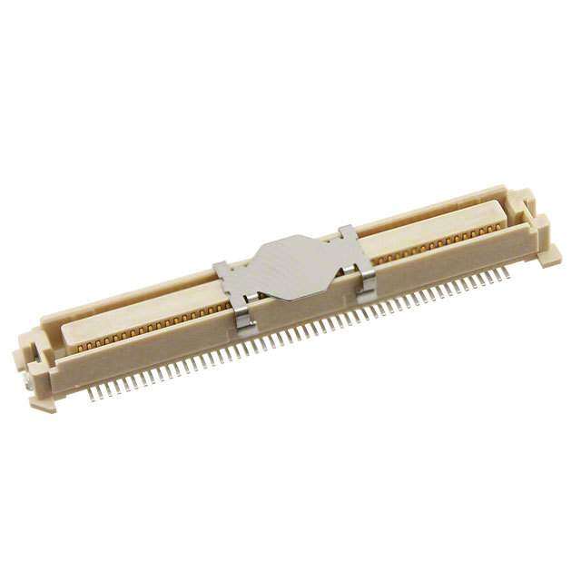
Hirose Electric Co Ltd的DF40C-90DS-0.4V(51)是一款超薄、高密度的矩形连接器,属于边缘型、夹层式(板对板)连接器,广泛应用于对空间和厚度要求严苛的高性能电子设备中。其主要应用场景包括:

1. 移动通信设备:如智能手机、平板电脑等,用于主板与副板之间的高速信号传输,因其0.4mm超小间距和低剖面设计,可有效节省内部空间,满足轻薄化需求。
2. 便携式消费电子产品:如数码相机、可穿戴设备(智能手表、AR/VR设备),适用于多层PCB堆叠结构,实现稳定可靠的电气连接。
3. 工业与医疗电子:在小型化工业传感器、便携式医疗监测设备中,该连接器提供良好的抗振动性能和耐久性,确保复杂环境下的稳定运行。
4. 汽车电子系统:用于车载信息娱乐系统、驾驶辅助模块等紧凑型控制单元,支持高频信号传输,具备优良的机械强度和可靠性。

DF40C-90DS-0.4V(51)支持差分信号传输,具有优异的电气性能和屏蔽特性,适合高速数据传输应用。其表面贴装(SMT)安装方式便于自动化生产,提升制造效率。综上,该型号连接器适用于追求小型化、高密度、高可靠性的现代电子系统。
| 参数 | 数值 |
| 产品目录 | |
| 描述 | CONN RCPT 90POS 0.4MM GOLD SMD板对板与夹层连接器 0.4MM 90P SMT RECPT VT 1.5MM HT NO FITT |
| 产品分类 | 矩形 - 板对板连接器 - 阵列,边缘型,夹层式板对板与夹层连接器 |
| 品牌 | Hirose Connector |
| 产品手册 | |
| 产品图片 |
|
| rohs | 符合RoHS无铅 / 符合限制有害物质指令(RoHS)规范要求 |
| 产品系列 | Hirose Connector DF40C-90DS-0.4V(51)DF40 |
| 数据手册 | |
| 产品型号 | DF40C-90DS-0.4V(51) |
| 产品培训模块 | http://www.digikey.cn/PTM/IndividualPTM.page?site=cn&lang=zhs&ptm=25203 |
| 产品目录绘图 |
|
| 产品目录页面 | |
| 产品种类 | 板对板与夹层连接器 |
| 产品类型 | Receptacles |
| 位置数量 | 90 |
| 其它名称 | *DF40C-90DS-0.4V(51) |
| 包装 | 剪切带 (CT) |
| 叠放高度 | 1.5 mm |
| 商标 | Hirose Connector |
| 外壳材料 | Liquid Crystal Polymer (LCP) |
| 安装类型 | 表面贴装 |
| 安装角 | Vertical |
| 封装 | Reel |
| 工厂包装数量 | 5000 |
| 排数 | 2 |
| 接合堆叠高度 | 1.5mm |
| 板上高度 | 0.057"(1.45mm) |
| 标准包装 | 1 |
| 特性 | - |
| 特色产品 | http://www.digikey.com/cn/zh/ph/Hirose/DF40.html |
| 电压额定值 | 30 V |
| 电流额定值 | 300 mA |
| 端接类型 | SMD |
| 系列 | DF40 |
| 节距 | 0.4 mm |
| 触头镀层 | 金 |
| 触头镀层厚度 | - |
| 触点材料 | Phosphor Bronze |
| 触点电镀 | Gold |
| 连接器类型 | 插座,中央带触点 |
| 配套产品 | /product-detail/zh/DF40C-90DP-0.4V(51)/H11878DKR-ND/2349562/product-detail/zh/DF40C-90DP-0.4V(51)/H11878CT-ND/2349560/product-detail/zh/DF40C-90DP-0.4V(51)/H11878TR-ND/2349558 |
| 针脚数 | 90 |
| 间距 | 0.016"(0.40mm) |


-80DP-0.5V(86).jpg)
.jpg)
-30DP-0.5V(57).jpg)
-44DP-0.4V(75).jpg)
-50DP-0.5V(86).jpg)
PDF Datasheet 数据手册内容提取
0.4mm Pitch, 1.5 to 4.0mm Height, Board-to-Board and Board-to-FPC Connectors DF40 Series Space saving Space saving (cid:45)(cid:37)(cid:21)(cid:101)(cid:100)(cid:104)(cid:35)(cid:33)(cid:21)(cid:37)(cid:35)(cid:41)(cid:21)(cid:98)(cid:98)(cid:21)(cid:101)(cid:94)(cid:105)(cid:88)(cid:93)(cid:33)(cid:21)(cid:38)(cid:35)(cid:42)(cid:21)(cid:98)(cid:98)(cid:21)(cid:93)(cid:90)(cid:94)(cid:92)(cid:93)(cid:105) (cid:58)(cid:109)(cid:94)(cid:104)(cid:105)(cid:94)(cid:99)(cid:92) (cid:101)(cid:103)(cid:100)(cid:89)(cid:106)(cid:88)(cid:105)(cid:104) (cid:98) d. (cid:98) (cid:98) serve (cid:57)(cid:59)(cid:41)(cid:37) (cid:40)(cid:35)(cid:40)(cid:45)(cid:98) (cid:42)(cid:35)(cid:37) e R s (cid:38)(cid:45)(cid:35)(cid:43)(cid:98)(cid:98) ht g Ri All D. ■Features T High contact reliability - effective mating length 0.45mm L O., 1. High density mounting C Space saving design that has a minimum connector (cid:72)(cid:93)(cid:100)(cid:88)(cid:96)(cid:21)(cid:86)(cid:87)(cid:104)(cid:100)(cid:103)(cid:101)(cid:105)(cid:94)(cid:100)(cid:99)(cid:21)(cid:103)(cid:94)(cid:87)(cid:104) C width, yet still retains a sufficient vacuum area for RI easy pick-and-place mounting T Minimum width : 3.38mm C SE ELE 2. MIhne uaigdlhdttisitp ioalnree t oas vtitaasi lcaspbkla ehc aeen sidag vahidntdg ovdepersstiiagotniln,i tsyse tvoe aranly s tack (cid:37)(cid:35)(cid:41)(cid:42)(cid:98)(cid:98) (cid:38)(cid:35)(cid:42)〜(cid:41)(cid:35)(cid:37)(cid:98)(cid:98) O application. Stack heights : 1.5mm, 2.0mm, 2.5mm, R HI 3.0mm, 3.5mm, and 4.0mm. 8 3. High contact reliability 1 0 Despite its small stature and low profile, the contacts (cid:65)(cid:100)(cid:88)(cid:96)(cid:21)(cid:104)(cid:110)(cid:104)(cid:105)(cid:90)(cid:98) 2 ht deliver strong contact forces and an effective mating (cid:29)(cid:38)(cid:37)(cid:21)(cid:101)(cid:100)(cid:104)(cid:35)(cid:21)(cid:105)(cid:100)(cid:21)(cid:42)(cid:37)(cid:21)(cid:101)(cid:100)(cid:104)(cid:35)(cid:30) g length of 0.45mm on the 1.5mm stacking height. ri y This connector utilizes a locking system that prevents p o accidental unmating issues and emits a clear tactile C Stacking height variations 8 click to ensure that mating has been completed. 1 4. Excellent self-aligning range Standard type 0 2 Stacking 1.5 2.0 2.5 3.0 3.5 4.0 1. The use of guide ribs allows 0.33mm of self- height mm mm mm mm mm mm c. alignment on this connector. 10 ○ − ○ − − − e D 5. Reinforced structure with shock absorbing ribs 12 ○ ○ − − − − 20 ○ ○ ○ − ○ − Both sides of the connector have been reinforced 24 ○ ○ − − − − with the addition of shock absorbing ribs. s 30 ○ ○ ○ ○ ○ − 6. Solder wicking prevention act 34 ○ − − − − − Nickel-plated barriers were added to protect the ont 40 ○ ○ ○ ○ ○ − C contact areas from potential solder wicking. of 44 − ○ − ○ − − 7. Contamination resistant design o. 50 ○ ○ ○ ○ ○ ○ N 60 ○ ○ ○ ○ ○ ○ When mated, the connector’s design covers the 70 ○ ○ − ○ − − contacts which help to keep dust and other debris away 80 ○ ○ − ○ ○ ○ from the contacts. The SMT leads are kept very close 90 ○ − − ○ − ○ to the connector housing which also helps to prevent 100 ○ − − ○ − − shorts caused by debris on the exposed contacts. 8. RoHS compliant Shielded type Environment friendly and does not use RoHS Stacking 1.5 3.0 specified prohibited materials. height mm mm Apallr mtsa ctoemriaplsly awnidth s tuhbes RtaonHceSs s utasnedda trod sp.roduce these No. of ontacts 3408 ○○ ○− C 70 − ○ 9. High speed signal with noise prevention The shielded type can support high speed signal transmissions with noise prevention. Ipnl ecaassee sc ownhtaecret ath ceo ampppalincya trieopnr ewsielln dteamtivaen fdo ar fhuirgthh eler vineflo orfm raetliiaobni.lity, such as automotive, 2016.4⑤ 1
DF40 Series●0.4mm Pitch, 1.5 to 4.0mm Height, Board-to-Board and Board-to-FPC Connectors ■Product Specifi cations Operating Temperature Range Storage Temperature Range Rated Current 0.3A -35 to +85℃ (Note 1) -10 to +60℃ (Note 2) Ratings Rated Voltage AC, DC 30V Operating Humidity Range Storage Humidity Range 20 to 80% 40 to 70% (Note 2) Items Specifi cations Conditions 1. Insulation Resistance 50Mø min Measured with DC 100V 2. Withstanding Voltage No fl ashover or breakdown Apply AC 100V for 1 minute 3. Contact Resistance 90mø max Measured with AC 20mV, 1 kHz and 1mA Frequency 10-55 Hz, half amplitude 0.75mm, 4. Vibration Resistance No electrical discontinuity of 1µs or greater 3 directions for 2 hours d. Contact resistance : 90mø max Left at temperature 40 ± 2ç, humidity 90 to 95%, e 5. Humidity Resistance rv Insulation resistance : 25mø min 96 hours e s e Contact resistance : 90mø max (-55ç : 30 minutes → 5~35ç : 10 minutes → 85ç : 30 R 6. Temperature Cycles s Insulation resistance : 50mø min minutes →5~35ç : 10 minutes) 5 cycles ht g Ri 7. Durability Contact resistance : 90mø max 30 mating cycles All D. Refl ow : according to the Recommended 8. Soldering Heat Should be no melting of resin parts that affects Temperature Profi le T L Resistance its performance Hand solder : S oldering iron temperature 350ç, O., no more than 3 seconds. C C Note 1 : Includes temperature rise caused by current fl ow. RI Note 2 : The term "storage" here refers to products stored for a long period prior to board mounting and use. The operating T temperature and humidity range covers the non-energized condition of connectors after board mounting and the C E temporary storage conditions during transportation, etc. L E E ■Materials (Standard, non shielded type) / Finish S O R Product Component Materials Finish UL Regulation HI 8 Receptacle Insulator LCP Black UL94V-0 1 Contact Phosphor bronze Gold plating --------------- 0 2 Insulator LCP Black UL94V-0 ht Header Contact Phosphor bronze Gold plating --------------- g ri y p o ■Materials (Shielded type) / Finish C 8 Product Component Materials Finish UL Regulation 1 0 2 Insulator LCP Black UL94V-0 1. Receptacle Contact --------------- c. Phosphor bronze Gold plating e Shield plate --------------- D Insulator LCP Black UL94V-0 Header Contact --------------- Phosphor bronze Gold plating Reinforcing metal fi tting --------------- 2
DF40 Series●0.4mm Pitch, 1.5 to 4.0mm Height, Board-to-Board and Board-to-FPC Connectors ■Product Number Structure (Standard, non-shielded type) Refer to the chart below when determining the product specifications from the product number. Please select from the product numbers listed in this catalog when placing orders. ●Receptacle DF40 # − (**) − * DS − 0.4 V (**) ❶ ❷ ❸ ❹ ❺ ❻ ❼ ❽ ❶ Series Name: DF40 ❸ Stacking height ❹ No. of Contacts ❷ Style Display Stacking height ❺ Connector Type B : With reinforcing metal fi tting None 1.5mm DS : Double row receptacle HB : With reinforcing metal fi tting 2.0 2.0mm d. ❻ Contact Pitch : 0.4mm e (The H denotes a stacking height 2.5mm or above) 2.5 2.5mm rv C : Without reinforcing metal fi tting 3.0 3.0mm ❼ Mating direction Shape V : Vertical SMT e es HC : Without reinforcing metal fi tting 3.5 3.5mm ❽ Packaging Type R (The H denotes a stacking height 2.5mm or above) 4.0 4.0mm (51) Embossed tape packaging s ht g ●Header Ri All DF40 # − * DP − 0.4 V (**) D. ❶ ❷ ❸ ❹ ❺ ❻ ❼ T L O., ❶ Series Name : DF40 ❸ No. of Contacts ❺ Contact Pitch : 0.4mm C C ❷ Style ❹ Connector Type ❻ Mating direction V : Vertical SMT RI C : Without reinforcing metal fi tting DP : Double row pin header ❼ Packaging Type T C (51) Embossed tape packaging E L E E S O ■Shielded type R HI 8 ●Receptacle 1 20 DF40 GB − (**) − * DS − 0.4 V (**) ht g ❶ ❷ ❸ ❹ ❺ ❻ ❼ ❽ ri y p o C ❶ Series Name : DF40 ❸ Stacking height ❺ Connector Type 8 ❷ Style Display Stacking height DS : Double row receptacle 1 20 GB : With shield 1.5 1.5mm ❻ Contact Pitch : 0.4mm 1. 3.0 3.0mm c. ❼ Mating direction V : Vertical SMT e D ❹ No. of Contacts ❽ Packaging Type (51) Embossed tape packaging ●Header DF40 GB − * DP − 0.4 V (**) ❶ ❷ ❸ ❹ ❺ ❻ ❼ ❶ Series Name : DF40 ❸ No. of Contacts ❺ Contact Pitch : 0.4mm ❷ Style ❹ Connector Type ❻ Mating direction V : Vertical SMT GB : With reinforcing metal fi tting DP : Double row pin header ❼ Packaging Type (For use with shielded product ) (51) Embossed tape packaging 3
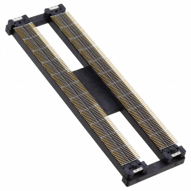
DF40 Series●0.4mm Pitch, 1.5 to 4.0mm Height, Board-to-Board and Board-to-FPC Connectors ■Receptacle (Stacking height 1.5mm) A±0.2 B±0.08 P=0.4±0.05 2 2 0. 0. ± ± 8 8 3 8 3. 2. 0.12±0.02 Vacuum pick up area : C±0.2 ed. ±0.15 v D r e s e R s ht BRecommended PCB layout g Ri All D. B±0.02 B±0.02 1.2±0.02 T L P=0.4±0.02 P=0.4±0.02 O., C C LECTRI +0.053.78 0 02.38-0.051.5MAX +0.053.78 0 02.38-0.051.5MAX E E S O R 0.2±0.02 0.2±0.02 HI 8 DF40C(Without reinforcing metal fitting) DF40B(With reinforcing metal fitting) 1 0 2 ht g ri ■Stacking height 1.5mm y 【Specification No.】 p o (51) : Embossed package 5,000 pcs/reel C 8 1 Unit : mm 0 2 Part No. HRS No. No. of Contacts A B C D 1. c. DF40B-10DS-0.4V(51) 684-4038-8 51 10 4.6 1.6 e 1.0 D DF40B-12DS-0.4V(51) 684-4152-3 51 12 5.0 2.0 DF40B-30DS-0.4V(51) 684-4090-8 51 30 8.6 5.6 1.5 DF40B-50DS-0.4V(51) 684-4018-0 51 50 12.6 9.6 DF40B-60DS-0.4V(51) 684-4049-4 51 60 14.6 11.6 3.2 DF40B-80DS-0.4V(51) 684-4052-9 51 80 18.6 15.6 DF40C-20DS-0.4V(51) 684-4005-9 51 20 6.6 3.6 1.0 DF40C-24DS-0.4V(51) 684-4006-1 51 24 7.4 4.4 1.2 DF40C-30DS-0.4V(51) 684-4007-4 51 30 8.6 5.6 1.5 1.45 DF40C-34DS-0.4V(51) 684-4023-0 51 34 9.4 6.4 2.3 DF40C-40DS-0.4V(51) 684-4008-7 51 40 10.6 7.6 DF40C-50DS-0.4V(51) 684-4009-0 51 50 12.6 9.6 DF40C-60DS-0.4V(51) 684-4004-6 51 60 14.6 11.6 DF40C-70DS-0.4V(51) 684-4016-5 51 70 16.6 13.6 3.2 DF40C-80DS-0.4V(51) 684-4002-0 51 80 18.6 15.6 DF40C-90DS-0.4V(51) 684-4124-8 51 90 20.6 17.6 DF40C-100DS-0.4V(51) 684-4033-4 51 100 22.6 19.6 Note 1 : Please place orders by full reel. Note 2 : The surface of the 60 to 100 pos. parts have a small, concave section that will not affect the vacuum pick up operation. Note 3 : Resist coating area. Note 4 : This connector is NOT polarized. 4
DF40 Series●0.4mm Pitch, 1.5 to 4.0mm Height, Board-to-Board and Board-to-FPC Connectors ■Receptacle (Stacking height 2.0mm) A±0.2 B±0.08 P=0.4±0.05 2 2 0. 0. ± ± 8 4 3 9 3. 2. 0.12±0.02 Vacuum pick up area : C±0.2 d. 5 erve D±0.1 s e R s ht BRecommended PCB layout g Ri All D. B±0.02 B±0.02 1.2±0.02 T L P=0.4±0.02 P=0.4±0.02 O., C C LECTRI +0.053.78 0 02.38-0.051.5MAX +0.053.78 0 02.38-0.051.5MAX E E S O R 0.2±0.02 0.2±0.02 HI 8 DF40C(Without reinforcing metal fitting) DF40B(With reinforcing metal fitting) 1 0 2 ht g ri y p o ■Stacking height 2.0mm C 【Specification No.】 8 (51) : Embossed package 4,000 pcs/reel 1 0 2 Unit : mm 1. c. Part No. HRS No. No. of Contacts A B C D e D DF40B(2.0)-12DS-0.4V(51) 684-4150-8 51 12 5.0 2.0 1.0 DF40B(2.0)-80DS-0.4V(51) 684-4128-9 51 80 18.6 15.6 3.2 DF40C(2.0)-20DS-0.4V(51) 684-4040-0 51 20 6.6 3.6 1.0 DF40C(2.0)-24DS-0.4V(51) 684-4021-2 51 24 7.4 4.4 1.2 DF40C(2.0)-30DS-0.4V(51) 684-4058-5 51 30 8.6 5.6 1.5 1.95 DF40C(2.0)-40DS-0.4V(51) 684-4042-5 51 40 10.6 7.6 DF40C(2.0)-50DS-0.4V(51) 684-4091-0 51 50 12.6 9.6 DF40C(2.0)-60DS-0.4V(51) 684-4034-7 51 60 14.6 11.6 3.2 DF40C(2.0)-70DS-0.4V(51) 684-4147-3 51 70 16.6 13.6 DF40C(2.0)-80DS-0.4V(51) 684-4132-6 51 80 18.6 15.6 Note 1 : Please place orders by full reel. Note 2 : The surface of the 60 to 100 pos. parts have a small, concave section that will not affect the vacuum pick up operation. Note 3 : Resist coating area. Note 4 : This connector is NOT polarized. 5
DF40 Series●0.4mm Pitch, 1.5 to 4.0mm Height, Board-to-Board and Board-to-FPC Connectors ■Receptacle (Stacking height 2.5mm to 4.0mm) A±0.2 B±0.08 P=0.4±0.05 2 2 0. 0. ± ± 8 4 3 9 3. 2. 0.12±0.02 Vacuum pick up area : C±0.2 d. 5 erve D±0.1 s e R hts BRecommended PCB layout g Ri B±0.02 B±0.02 1.2±0.02 All P=0.4±0.02 P=0.4±0.02 D. T L RIC CO., +0.053.78 0 02.38-0.050.92MAX +0.053.78 0 02.38-0.051.5MAX T C E L 0.2±0.02 0.2±0.02 E E S DF40HC(Without reinforcing metal fitting) DF40HB(With reinforcing metal fitting) O R ■Stacking height 2.5mm 【Specification No.】 HI (51) : Embossed package 3,000 pcs/reel 8 1 0 2 Unit : mm ht Part No. HRS No. No. of Contacts A B C D g yri DF40HB(2.5)-10DS-0.4V(51) 684-4189-3 51 10 4.6 1.6 p 1.0 o DF40HC(2.5)-20DS-0.4V(51) 684-4126-3 51 20 6.6 3.6 C 8 DF40HC(2.5)-40DS-0.4V(51) 684-4112-9 51 40 10.6 7.6 2.4 1 0 DF40HC(2.5)-50DS-0.4V(51) 684-4101-2 51 50 12.6 9.6 3.2 2 1. DF40HC(2.5)-60DS-0.4V(51) 684-4085-8 51 60 14.6 11.6 c. e D ■Stacking height 3.0mm 【Specification No.】 (51) : Embossed package 3,000 pcs/reel Unit : mm Part No. HRS No. No. of Contacts A B C D DF40HC(3.0)-30DS-0.4V(51) 684-4098-0 51 30 8.6 5.6 1.5 DF40HC(3.0)-40DS-0.4V(51) 684-4169-6 51 40 10.6 7.6 DF40HC(3.0)-44DS-0.4V(51) 684-4076-7 51 44 11.4 8.4 DF40HC(3.0)-50DS-0.4V(51) 684-4099-2 51 50 12.6 9.6 DF40HC(3.0)-60DS-0.4V(51) 684-4100-0 51 60 14.6 11.6 2.9 3.2 DF40HC(3.0)-70DS-0.4V(51) 684-4138-2 51 70 16.6 13.6 DF40HC(3.0)-80DS-0.4V(51) 684-4180-9 51 80 18.6 15.6 DF40HC(3.0)-90DS-0.4V(51) 684-4161-4 51 90 20.6 17.6 DF40HC(3.0)-100DS-0.4V(51) 684-4151-0 51 100 22.6 19.6 Note 1 : Please place orders by full reel. Note 2 : The surface of the 60 to 100 pos. parts have a small, concave section that will not affect the vacuum pick up operation. Note 3 : Resist coating area. Note 4 : This connector is NOT polarized. 6
DF40 Series●0.4mm Pitch, 1.5 to 4.0mm Height, Board-to-Board and Board-to-FPC Connectors ■Stacking height 3.5mm 【Specification No.】 (51) : Embossed package 2,000 pcs/reel Unit : mm Part No. HRS No. No. of Contacts A B C D DF40HC(3.5)-20DS-0.4V(51) 684-4188-0 51 20 6.6 3.6 1.0 DF40HC(3.5)-30DS-0.4V(51) 684-4136-7 51 30 8.6 5.6 1.5 DF40HC(3.5)-40DS-0.4V(51) 684-4209-9 51 40 10.6 7.6 3.4 DF40HC(3.5)-50DS-0.4V(51) 684-4109-4 51 50 12.6 9.6 3.2 DF40HC(3.5)-60DS-0.4V(51) 684-4102-5 51 60 14.6 11.6 DF40HC(3.5)-80DS-0.4V(51) 684-4162-7 51 80 18.6 15.6 d. e rv ■Stacking height 4.0mm e 【Specification No.】 s e (51) : Embossed package 2,000 pcs/reel R s ht Unit : mm g Ri Part No. HRS No. No. of Contacts A B C D All DF40HB(4.0)-50DS-0.4V(51) 684-4104-0 51 50 12.6 D. DF40HC(4.0)-50DS-0.4V(51) 684-4215-1 51 50 12.6 9.6 T L DF40HC(4.0)-60DS-0.4V(51) 684-4133-9 51 60 14.6 11.6 3.2 3.9 O., DF40HC(4.0)-80DS-0.4V(51) 684-4140-4 51 80 18.6 15.6 C C DF40HC(4.0)-90DS-0.4V(51) 684-4165-5 51 90 20.6 17.6 RI Note 1 : Please place orders by full reel. T C Note 2 : The surface of the 60 to 100 pos. parts have a small, concave section that will not affect the vacuum pick up operation. E Note 3 : Resist coating area. L E Note 4 : This connector is NOT polarized. E S O R HI 8 1 0 2 ht g ri y p o C 8 1 0 2 1. c. e D 7
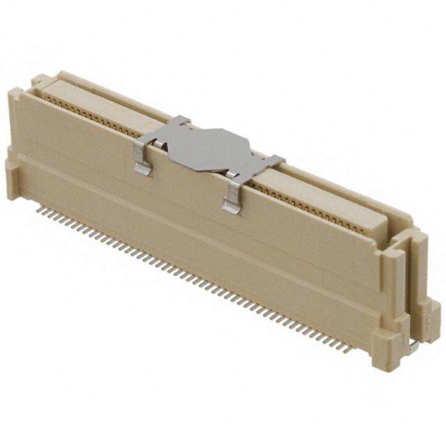
DF40 Series●0.4mm Pitch, 1.5 to 4.0mm Height, Board-to-Board and Board-to-FPC Connectors ■Receptacle (Stacking height 1.5mm, with shield) < 30 contact > 8.64±0.3 6.48±0.1 5.6±0.08 P=0.4±0.05 3 0. ± 8 3 3. 0.2±0.02 0.12±0.02 Vacuum pick up area: 1.5±0.2 ed. 3.12±0.2 v 5 r 1 se 0.± e 5 R 4 s 1. ht g Ri < 48 contact > All D. 1120..2048±±00..13 T 9.2±0.08 L O., P=0.4±0.05 3.2±0.08 C C 3 RI 0.± T 38 C 3. E L E 0.2±0.02 0.12±0.02 E 0.12±0.02 Vacuum pick up area: 3.2±0.2 S O 3.12±0.2 R 8 HI 0.15± 1 45 0 1. 2 ht g yri BRecommended PCB layout p o C 8 < 30 contact > < 48 contact > 10.08±0.02 1 6.48±0.02 9.2±0.02 20 5.6±0.02 3.2±0.02 1. P=0.4±0.02 P=0.4±0.02 0.6±0.02 0.6±0.02 c. e D 0.05+3.78 0 02.380.05−1.5MAX 02.640.05−0.05+4.08 0 0.05+4.08 00.05+3.78 0 02.380.05−1.5MAX 02.640.05−0.05+4.08 0 0.2±0.02 0.28±0.02 0.2±0.02 0.6±0.02 0.28±0.02 ■Stacking height 1.5mm 【Specification No.】 (51) : Embossed package 5,000 pcs/reel Unit : mm Part No. HRS No. No. of Contacts Signal contact Ground contact DF40GB(1.5)-30DS-0.4V(51) 684-4198-4 51 30 30 4 DF40GB(1.5)-48DS-0.4V(51) 684-4194-3 51 48 40 12 Note 1 : Please place orders by full reel. Note 2 : Resist coating area. Note 3 : This connector is NOT polarized. 8
DF40 Series●0.4mm Pitch, 1.5 to 4.0mm Height, Board-to-Board and Board-to-FPC Connectors ■Receptacle (Stacking height 3.0mm, with shield) < 48 contact > 12.24±0.3 10.08±0.1 9.2±0.08 P=0.4±0.05 3.2±0.08 3 0. ± 8 3 3. 0.2±0.02 0.12±0.02 0.12±0.02 Vacuum pick up area: 3.2±0.2 3.12±0.2 d. e v 5 ser 0.1± e 9 R 2. s ht g < 70 contact > Ri All 1163..66±4±0.00.83 D. P=0.4±0.05 39..62±±00..0088 T L O., C 0.3 0.20.2 C 8± 8±8± RI 3.3 3.33.6 T C E L 0.2±0.02 0.12±0.05 Vacuum pick up area: 3.2±0.2 E 0.12±0.02 E 3.12±0.2 S O R 5 1 HI 0. ± 8 9 1 2. 0 2 ht g yri BRecommended PCB layout p o C 018 < 48 contact > 10.08±0.02 < 70 contact > 1143.4.68±±00.0.022 2 9.2±0.02 9.2±0.02 1. 3.2±0.02 P=0.4±0.02 3.6±0.02 c. P=0.4±0.02 0.6±0.02 0.6±0.02 e D 0.05+4.08 00.05+3.78 0 02.380.05−1.5MAX 02.640.05−0.05+4.08 0 0.05+4.08 00.05+3.78 0 02.380.05−1.5MAX 02.640.05−0.05+4.08 0 0.2±0.02 0.6±0.02 0.28±0.02 0.2±0.02 0.6±0.02 0.6±0.02 0.6±0.02 0.28±0.02 ■Stacking height 3.0mm 【Specification No.】 (51) : Embossed package 3,000 pcs/reel Unit : mm Part No. HRS No. No. of Contacts Signal contact Ground contact DF40GB(3.0)-48DS-0.4V(51) 684-4197-1 51 48 40 12 DF40GB(3.0)-70DS-0.4V(51) 684-4196-9 51 70 54 20 Note 1 : Please place orders by full reel. Note 2 : The surface of the 70 pos. part have a small, concave section that will not affect the vacuum pick up operation. Note 3 : Resist coating area. Note 4 : This connector is NOT polarized. 9
DF40 Series●0.4mm Pitch, 1.5 to 4.0mm Height, Board-to-Board and Board-to-FPC Connectors ■Header A±0.2 B±0.08 P=0.4±0.05 2 2 0. 0. ± ± 7 5 9 8 2. 1. 0.15±0.02 Vacuum pick up area : C±0.2 15 0. d. 4± ve 1.1 r e s e R s ht BRecommended PCB layout g Ri All D. (cid:55)(cid:164)(cid:37)(cid:35)(cid:37)(cid:39) (cid:37)(cid:35)(cid:43)(cid:42)(cid:164)(cid:37)(cid:35)(cid:37)(cid:39) T (cid:69)(cid:50)(cid:37)(cid:35)(cid:41)(cid:164)(cid:37)(cid:35)(cid:37)(cid:39) (cid:37)(cid:35)(cid:40)(cid:164)(cid:37)(cid:35)(cid:37)(cid:39) L O., C C CTRI (cid:32)(cid:37)(cid:35)(cid:37)(cid:42)(cid:40)(cid:44)(cid:21)(cid:37)(cid:21)(cid:37)(cid:37)(cid:42)(cid:34)(cid:37)(cid:35)(cid:37)(cid:42) E (cid:40)(cid:35) (cid:39)(cid:35) L E E S O R (cid:37)(cid:35)(cid:39)(cid:40)(cid:164)(cid:37)(cid:35)(cid:37)(cid:39) (cid:37)(cid:35)(cid:40)(cid:42)(cid:164)(cid:37)(cid:35)(cid:37)(cid:39) HI 8 1 0 2 ht g Unit : mm ri y Part No. HRS No. No. of Contacts A B C p o C DF40C-10DP-0.4V(51) 684-4035-0 51 10 3.52 1.6 8 DF40C-12DP-0.4V(51) 684-4149-9 51 12 3.92 2.0 1.0 1 20 DF40C-20DP-0.4V(51) 684-4010-9 51 20 5.52 3.6 1. c. DF40C-24DP-0.4V(51) 684-4011-1 51 24 6.32 4.4 1.2 e D DF40C-30DP-0.4V(51) 684-4012-4 51 30 7.52 5.6 1.5 DF40C-34DP-0.4V(51) 684-4024-3 51 34 8.32 6.4 2.3 DF40C-40DP-0.4V(51) 684-4013-7 51 40 9.52 7.6 DF40C-44DP-0.4V(51) 684-4077-0 51 44 10.32 8.4 DF40C-50DP-0.4V(51) 684-4014-0 51 50 11.52 9.6 DF40C-60DP-0.4V(51) 684-4003-3 51 60 13.52 11.6 3.2 DF40C-70DP-0.4V(51) 684-4015-2 51 70 15.52 13.6 DF40C-80DP-0.4V(51) 684-4001-8 51 80 17.52 15.6 DF40C-90DP-0.4V(51) 684-4125-0 51 90 19.52 17.6 DF40C-100DP-0.4V(51) 684-4032-1 51 100 21.52 19.6 Note 1 : Please place orders by full reel. Note 2 : There are no concave parts on the header side contact part to increase the mating strength for 60 pos. or above. Note 3 : Use the contacts at the four corners as metal fi ttings. Do not use them as signal or power contacts. Note 4 : The surface of the 90 pos and higher parts have a small, concave section that will not affect the vacuum pick up operation. Note 5 : This connector is NOT polarized. 10
DF40 Series●0.4mm Pitch, 1.5 to 4.0mm Height, Board-to-Board and Board-to-FPC Connectors ■Header (For use with shielded product) A±0.3 B±0.1 C±0.08 P=0.4±0.05 0.2±0.2±0.2± 725 2.92.01.8 0.15±0.02 Vacuum pick up area: G±0.2 d. e v ser 0.08±0.02 1.52±0.2 0.15± Re 1.14 s ht BRecommended PCB layout g Ri All D+ 00.05 D. E 0 T −0.05 L B±0.02 O., F 0 C −0.05 C C±0.02 RI P=0.4±0.02 0.35±0.02 T C E L SE E 0.057+ 0 050.05− 0.052+ 0 0.052+ 0 O 3.3 2.0 2.4 3.3 R HI 2018 0.23±0.02 020.05− 080.05− ht 1.0 1.8 g ri y p o C Unit : mm 8 Part No. HRS No. No. of Contacts A B C D E F G 1 20 DF40GB-30DP-0.4V(51) 684-4200-4 51 30 7.16 6.67 5.6 8.74 7.32 6.12 1.5 1. c. DF40GB-48DP-0.4V(51) 684-4195-6 51 48 10.76 10.27 9.2 12.34 10.92 9.72 3.2 e D DF40GB-70DP-0.4V(51) 684-4199-7 51 70 15.16 14.67 13.6 16.74 15.32 14.12 3.2 Note 1 : Please place orders by full reel. Note 2 : There are no concave parts of header side contact part to increase the mating strength for 60 pos. or above. Note 3 : Resist coating area. Note 4 : This connector is NOT polarized. 11
DF40 Series●0.4mm Pitch, 1.5 to 4.0mm Height, Board-to-Board and Board-to-FPC Connectors BEmbossed Carrier Tape Dimensions (JIS C 0806 compliant) ●Receptacle (Stacking height 1.5mm) ●Reel Condition Dimensions 1 0. Product label Ø1.5 0+0.1 2±0.1 4±0.1 F 1.75± F-F Ø21±0. 2±0.5 Ø13±0.2 8 Ø1.5 holes for feed mechanism 1 A C±0. 120° 12 0° ±2 ±1 d. 0.10.3 Ø380 Ø80 e ±± v BA r e s e R s A ht G G E±0.5 g Ri D±1 All 8±0.1 H F 0.3±0.1 D. Unreeling Direction 5 T 1 CO., L 0.2±0.05 H R 0.75+ 0.01 G-G 1.65±0. C RI R T 0.7 EC 5 0+0.1 L E E ■Stacking height 1.5mm S Unit : mm O R Part No. A B C D E HI 8 DF40#-10DS-0.4V(51) − 1 0 DF40#-12DS-0.4V(51) − 2 16 7.5 21.5 17.5 ht DF40#-20DS-0.4V(51) − g ri DF40#-24DS-0.4V(51) − y op DF40#-30DS-0.4V(51) − C 8 DF40#-34DS-0.4V(51) − 1 DF40#-40DS-0.4V(51) 24 − 11.5 29.5 25.5 0 2 1. DF40#-50DS-0.4V(51) − ec. DF40#-60DS-0.4V(51) − D DF40#-70DS-0.4V(51) 32 28.4 14.2 37.5 33.5 DF40#-80DS-0.4V(51) DF40#-90DS-0.4V(51) 44 40.4 20.2 49.5 45.5 DF40#-100DS-0.4V(51) DF40GB(1.5)-30DS-0.4V(51) − 24 11.5 29.5 25.5 DF40GB(1.5)-48DS-0.4V(51) − Note 1 : For 10 to 60 contact position parts, the carrier tape only has one row of holes. The carrier for parts with 70 contacts and above has two rows of holes. 12
DF40 Series●0.4mm Pitch, 1.5 to 4.0mm Height, Board-to-Board and Board-to-FPC Connectors BEmbossed Carrier Tape Dimensions (JIS C 0806 compliant) ●Receptacle (Stacking height 2.0mm to 2.5mm) ●Reel Dimensions 1 4±0.1 0. Product label Ø ± 1.5 0+0.1 2±0.1 H 1.75 H-H Ø21±0. 2±0.5 Ø13±0.2 8 Ø1.5 holes for feed mechanism 1 ° C±0. 120 120° ±2 ±1 d. 13 Ø380 Ø80 e 0.0. v ±± er BA s G G e R s ht E±0.5 g Ri D±1 All D. LT 8±0.1 J H 0.3±0.1 C CO., 2±0.05 J R 0.75+ 0.01 15Unreeling Direction RI 0. G-G ±0. T F C R E 0. EL 75 0+0.1 E S O ■Stacking height 2.0mm R Unit : mm HI Part No. A B C D E F 8 DF40#(2.0)-12DS-0.4V(51) − 1 0 DF40#(2.0)-20DS-0.4V(51) 16 − 7.5 21.5 17.5 2 ht DF40#(2.0)-24DS-0.4V(51) − g DF40#(2.0)-30DS-0.4V(51) − ri py DF40#(2.0)-40DS-0.4V(51) 24 − 11.5 29.5 25.5 2.2 Co DF40#(2.0)-50DS-0.4V(51) − 8 DF40#(2.0)-60DS-0.4V(51) − 1 DF40#(2.0)-70DS-0.4V(51) 0 32 28.4 14.2 37.5 33.5 2 DF40#(2.0)-80DS-0.4V(51) 1. c. e D ■Stacking height 2.5mm Unit : mm Part No. A B C D E F DF40H#(2.5)-10DS-0.4V(51) − 16 7.5 21.5 17.5 DF40H#(2.5)-20DS-0.4V(51) − DF40H#(2.5)-40DS-0.4V(51) − 2.72 DF40H#(2.5)-50DS-0.4V(51) 24 − 11.5 29.5 25.5 DF40H#(2.5)-60DS-0.4V(51) − Note 1 : For 10 to 60 contact position parts, the carrier tape only has one row of holes. The carrier for parts with 70 contacts and above has two rows of holes. 13
DF40 Series●0.4mm Pitch, 1.5 to 4.0mm Height, Board-to-Board and Board-to-FPC Connectors BEmbossed Carrier Tape Dimensions (JIS C 0806 compliant) ●Receptacle (Stacking height 3.0mm to 4.0mm) ●Reel Condition Dimensions 1 Ø 4±0.1 ±0. Product label 1.5 0+0.1 2±0.1 H 1.75 H-H Ø21±0. 2±0.5 Ø13±0.2 8 Ø1.5 holes for feed mechanism ° 1 0 d. C±0. 12 120° Ø380±2 Ø80±1 e 13 v 0.0. r ±± e BA es G G R s ht E±0.5 g Ri D±1 All D. T L O., 8±0.1 J H 0.4±0.1 CTRIC C 0.2±0.05 J R 0.75+ 0.01 G-G F±0.15 Unreeling Direction E L R E 0. SE 75 0+0.1 O ■Stacking height 3.0mm R HI Unit : mm 8 Part No. A B C D E F 01 DF40H#(3.0)-30DS-0.4V(51) − ght 2 DDFF4400HH##((33..00))--4404DDSS--00..44VV((5511)) 24 −− 11.5 29.5 25.5 yri DF40H#(3.0)-50DS-0.4V(51) − p o DF40H#(3.0)-60DS-0.4V(51) − C DF40H#(3.0)-70DS-0.4V(51) 3.15 18 DF40H#(3.0)-80DS-0.4V(51) 32 28.4 14.2 37.5 33.5 1.20 DDFF4400HH##((33..00))--9100D0DSS-0-.04.V4V(5(15)1) 44 40.4 20.2 49.5 45.5 c. e DF40GB(3.0)-48DS-0.4V(51) 24 − 11.5 29.5 25.5 D DF40GB(3.0)-70DS-0.4V(51) 32 28.4 14.2 37.5 33.5 ■Stacking height 3.5mm Unit : mm Part No. A B C D E F DF40H#(3.5)-20DS-0.4V(51) 16 − 7.5 21.5 17.5 DF40H#(3.5)-30DS-0.4V(51) − DF40H#(3.0)-40DS-0.4V(51) − 3.72 24 11.5 29.5 25.5 DF40H#(3.5)-50DS-0.4V(51) − DF40H#(3.5)-60DS-0.4V(51) − ■Stacking height 4.0mm Unit : mm Part No. A B C D E F DF40H#(4.0)-50DS-0.4V(51) − 24 11.5 29.5 25.5 DF40H#(4.0)-60DS-0.4V(51) − 4.15 DF40H#(4.0)-80DS-0.4V(51) 32 28.4 14.2 37.5 33.5 DF40H#(4.0)-90DS-0.4V(51) 44 40.4 20.2 49.5 45.5 Note 1 : For 10 to 60 contact position parts, the carrier tape only has one row of holes. The carrier for parts with 70 contacts and above has two rows of holes. 14
DF40 Series●0.4mm Pitch, 1.5 to 4.0mm Height, Board-to-Board and Board-to-FPC Connectors ●Header ●Reel Dimensions 1 0. Ø 4±0.1 ± 1.5 0+0.1 2±0.1 F 1.75 F-F Product label 2±0.5 2 Ø21±0. Ø13±0. 8 Ø1.5 holes for feed mechanism A C±0.1 120° 12 0° ±2 ±1 13 Ø380 Ø80 0.0. ±± BA d. e v r e s e A E±0.5 R G G s D±1 ht g Ri All H F 0.3±0.1 O., LTD. 0.2±0.05 HØ0.75+ 0.01 G-G 1.34±0.15 Unreeling Direction C C Ø0. TRI 75 0+0.1 C E L Unit : mm E E Part No. A B C D E S O DF40C-10DP-0.4V(51) − R 12 5.5 17.5 13.5 HI DF40C-12DP-0.4V(51) − 8 DF40C-20DP-0.4V(51) − 1 20 DF40C-24DP-0.4V(51) 16 − 7.5 21.5 17.5 ht DF40C-30DP-0.4V(51) − g yri DF40C-34DP-0.4V(51) − p o DF40C-40DP-0.4V(51) − C 8 DF40C-44DP-0.4V(51) 24 − 11.5 29.5 25.5 1 0 DF40C-50DP-0.4V(51) − 2 1. DF40C-60DP-0.4V(51) − c. e DF40C-70DP-0.4V(51) D 32 28.4 14.2 37.5 33.5 DF40C-80DP-0.4V(51) DF40C-90DP-0.4V(51) 44 40.4 20.2 49.5 45.5 DF40C-100DP-0.4V(51) DF40GB-30DP-0.4V(51) 16 − 7.5 21.5 17.5 DF40GB-48DP-0.4V(51) − 24 11.5 29.5 25.5 DF40GB-70DP-0.4V(51) − Note 1 : For 10 to 60 contact position parts, the carrier tape only has one row of holes. The carrier for parts with 70 contacts and above has two rows of holes. 15
DF40 Series●0.4mm Pitch, 1.5 to 4.0mm Height, Board-to-Board and Board-to-FPC Connectors BOperating Precautions 1. Recommended Solder Profi le Temperature (ç) 250 250ç 220ç 200 60 seconds or below 180ç 150 150ç 100 90 to 120 seconds d. 50 e v r Normal e s temperature e R 0 50 100 150 200 250 300 s ht Heating time (sec.) g All Ri 【1C. oPnedaitkio tnesm】perature Maximum of 250ç D. 2. Heating part Minimum of 220ç within 60 seconds T 3. Preheating part 150 to 180ç 90 to 120 seconds L 4. Number of times Maximum of 2 cycles O., C Note 1 : The temperature shows PCB surface temperature near the connector lead part. C RI 2. Recommended hand solder T Soldering iron temperature 340 ±10ç, solder time no more than 3 seconds C conditions E L 3. Recommended screen thickness: Thickness : 0.12mm E E Opening ratio (pattern area ratio) Opening ratio : DS side 80% DP side 80% S O 4. Leaning of PCB R Max 0.02mm at the center of connector (using both edges of connector as criteria) HI 18 5. Washing Cleaning/washing is not recommended for this connector. Cleaning agents can 0 2 deteriorate the mechanical operation and the environmental resistance of this ht connector. g pyri 6. Precautions ■ Do not mate or unmate these connectors until they are mounted, failure to follow o C this precaution can lead to deformation or damage to these connectors. 8 ■ Provide another form of support to the PCB, this connector was not designed to 01 be the main form of support. 1.2 ■ Mating and unmating with excessive force can cause damage. c. ■ Do not apply excessive amounts of fl ux as it may cause excess solder and fl ux e D wicking. ■ There may be a slight variance in the color of the molding between production lots, this variance will not affect the performance of the connector. ■ Refer to the next page for the handling precautions when mating and unmating the connectors. ■ If the connector becomes disconnected due to impact, a fall or a counterforce to the FPC, it may be necessary to hold the connector in place with an addition to the device’s case or other cushioning material to hold the connector in place. 16
DF40 Series●0.4mm Pitch, 1.5 to 4.0mm Height, Board-to-Board and Board-to-FPC Connectors BPrecautions when connector mating DF40*-*DS-0.4V DF40*-*DS-0.4V d. e v r e s e R s ht g Ri All D. T L O., C C RI T C E L E E Prior to mating, locate the guidance ribs and S O align the header. R Do not apply excess force to the connector HI during mating. Doing so can lead to contact 8 1 damage. 0 2 ht g ri y p o C 8 1 0 2 1. c. e D Make sure that the connector is parallel to the other side, it then will drop down slightly. Continue to press it down until it is fully mated while maintaining the angle. Do not apply excessive force as it may damage the contacts. 17
DF40 Series●0.4mm Pitch, 1.5 to 4.0mm Height, Board-to-Board and Board-to-FPC Connectors BPrecautions when unmating a connector (cid:57)(cid:59)(cid:41)(cid:37)(cid:31)(cid:34)(cid:31)(cid:57)(cid:72)(cid:34)(cid:37)(cid:35)(cid:41)(cid:75) (cid:57)(cid:59)(cid:41)(cid:37)(cid:31)(cid:34)(cid:31)(cid:57)(cid:69)(cid:34)(cid:37)(cid:35)(cid:41)(cid:75) d. e v r e s e R s ht g Ri All D. T L O., To unmate this connector, lift evenly across C the header, making sure that each side stays C parallel to each other. RI T C E L E E S O R HI 8 If circumstances prevent the connectors from 1 0 staying parallel to each other, then one side 2 ht may be lifted as shown in the diagram. This g method is only approved if the connector is yri mounted onto an extremely rigid circuit board. p o If the board were to warp during this process C 8 it may result in damage to the connector or its 1 solder joints. 0 2 1. Do not try to disconnect these connectors by c. e pulling on one side or a corner, or unmate it D Pitch direction Corner direction while it is securely mounted onto a rigid FPC. These actions may lead to deformities and ultimately a damaged connector. As shown in the fi gure to the left, do not unmate it from the width direction (front to back), it may damage contacts. Width direction 18
DF40 Series●0.4mm Pitch, 1.5 to 4.0mm Height, Board-to-Board and Board-to-FPC Connectors BPrecautions when unmating a connector The contact may peel away if there is not enough rigidity in FPC. Receptacle FPC When mounting the receptacle side to FPC which does not have enough rigidity, the contact may peel away soldered connection. d. e v er Header We recommended to mount the header side to s e the FPC. R s ht g Ri Header We have conducted evaluations on the All requirements needed for FPC rigidity. If you D. need to mount the receptacle to the FPC, T FPC contact your local Hirose Rep for this data. L O., C C RI T C E L Receptacle E E S O R HI 8 1 0 2 ht g Even when mounting the header side to FPC, yri if the rigidity of FPC is low, the connector may p o break as shown in the left fi gure. Please check C 8 the strength and durability of FPC before using. 1 0 2 For the evaluation results of each item and FPC 1. rigidity, please contact us. c. e D 19
DF40 Series●0.4mm Pitch, 1.5 to 4.0mm Height, Board-to-Board and Board-to-FPC Connectors USA: USA: USA: HIROSE ELECTRIC (U.S.A.), INC. HEADQUARTERS CHICAGO OFFICE HIROSE ELECTRIC (U.S.A.), INC. SAN JOSE OFFICE HIROSE ELECTRIC (U.S.A.), INC. DETROIT OFFICE (AUTOMOTIVE) 2300 Warrenville Road, Suite 150, 2841 Junction Ave, Suite 200 17197 N. Laurel Park Drive, Suite 253, Downers Grove, IL 60515 San Jose, CA. 95134 Livonia, MI 48152 Phone : +1-630-282-6700 Phone : +1-408-253-9640 Phone : +1-734-542-9963 http://www.hirose.com/us/ Fax : +1-408-253-9641 Fax : +1-734-542-9964 http://www.hirose.com/us/ http://www.hirose.com/us/ THE NETHERLANDS: GERMANY: GERMANY: HIROSE ELECTRIC EUROPE B.V. HIROSE ELECTRIC EUROPE B.V. GERMAN BRANCH HIROSE ELECTRIC EUROPE B.V. NUREMBERG OFFICE Hogehillweg #8 1101 CC Amsterdam Z-O Schoenbergstr. 20, 73760 ostfildern Neumeyerstrasse 22-26, 90411 Nurnberg Phone : +31-20-6557460 Phone : +49-711-456002-1 Phone : +49-911 32 68 89 63 Fax : +31-20-6557469 Fax : +49-711-456002-299 Fax : +49-911 32 68 89 69 http://www.hirose.com/eu/ http://www.hirose.com/eu/ http://www.hirose.com/eu/ d. e v r e s e GERMANY: FRANCE: UNITED KINGDOM: R s HIROSE ELECTRIC EUROPE B.V. HANOVER OFFICE HIROSE ELECTRIC EUROPE B.V. PARIS OFFICE HIROSE ELECTRIC EUROPE BV (UK BRANCH) ht Bayernstr. 3, Haus C 30855 Langenhagen, Germany Regus La Garenne Colombes,Place de La Belgique, 4 Newton Court, Kelvin Drive, Knowlhill, g Ri Phone : +49-511 97 82 61 30 71 Boulevard National La Garenne Colombes, 92250, France Milton Keynes, MK5 8NH All Fax : +49-511 97 82 61 35 Phone : +33 (0) 1 7082 3170 Phone : +44-1908 202050 http://www.hirose.com/eu/ Fax : +33 (1) 7082 3101 Fax : +44-1908 202058 D. http://www.hirose.com/eu/ http://www.hirose.com/eu/ T L O., CHINA: CHINA: CHINA: C HIROSE ELECTRIC (SHANGHAI) CO., LTD. HIROSE ELECTRIC (SHANGHAI) CO.,LTD. BEIJING BRANCH HIROSE ELECTRIC TECHNOLOGIES (SHENZHEN) CO., LTD. C 1601, Henderson Metropolitan, NO.300, East Nanjing A1001, Ocean International Center, Building 56# East 4th Room 09-13, 19/F, Office Tower Shun Hing Square, Di Wang Commercial Centre, RI T Road, Huangpu District, Shanghai, China 200001 Ring Middle Road, ChaoYang District, Beijing, 100025 5002 Shen Nan Dong Road, Shenzhen City, Guangdong Province, 518008 C Phone : +86-21-6391-3355 Phone : +86-10-5165-9332 Phone : +86-755-8207-0851 E L Fax : +86-21-6391-3335 Fax : +86-10-5908-1381 Fax : +86-755-8207-0873 E E http://www.hirose.com/cn/ http://www.hirose.com/cn/ http://www.hirose.com/cn/ S O R HONG KONG: TAIWAN: KOREA: HI HIROSE ELECTRIC HONGKONG TRADING CO., LTD. HIROSE ELECTRIC TAIWAN CO., LTD. HIROSE KOREA CO.,LTD. 8 Room 1001, West Wing, Tsim Sha Tsui Centre, 66 103 8F, No.87, Zhengzhou Rd., Taipei 250, Huimanggongwon-ro, Siheung-si, 1 0 Mody Road, Tsim Sha Tsui East, Kowloon, Hong Kong Phone : +886-2-2555-7377 Gyeonggi-do, Korea, 15083 2 ht Phone : +852-2803-5338 Fax : +886-2-2555-7350 Phone : +82-31-496-7000 or 7124 g Fax : +852-2591-6560 http://www.hirose.com/tw/ Fax : +82-31-496-7100 ri y http://www.hirose.com/hk/ http://www.hirose.co.kr/ p o C 8 SINGAPORE: INDIA: INDIA: 1 HIROSE ELECTRIC SINGAPORE PTE. LTD. HIROSE ELECTRIC SINGAPORE PTE. LTD. DELHI LIAISON OFFICE HIROSE ELECTRIC SINGAPORE PTE. LTD. BANGALORE LIAISON OFFICE 0 2 10 Anson Road #26-16, International Plaza Office NO.552, Regus-Green Boulevard, Level5, Tower C, Unit No-403, 4th Floor, No-84, Barton Centre, Mahatma 1. c. 079903, Singapore Sec62, Plot B-9A, Block B, Noida, 201301, Uttar Pradesh, India Gandhi (MG) Road, Bangalore 560 001, Karnataka, India e Phone : +65-6324-6113 Phone : +91-12-660-8018 Phone : +91-80-4120 1907 D Fax : +65-6324-6123 Fax : +91-120-4804949 Fax : +91-80-4120 9908 http://www.hirose.com/sg/ http://www.hirose.com/sg/ http://www.hirose.com/sg/ MALAYSIA: THAILAND: PENANG REPRESENTATIVE OFFICE BANGKOK OFFICE (REPRESENTATIVE OFFICE) 1-21-01, Suntech @ Penang Cybercity (1164), Lintang Unit 4703, 47th FL., 1 Empire Tower, South Sathorn Mayang Pasir 3,11950, Bayan Baru, Penang, Malaysia. Road, Yannawa, Sathorn, Bangkok 10120 Thailand Phone : +604-619-2564 Phone : +66-2-686-1255 Fax : +604-619-2574 Fax : +66-2-686-3433 http://www.hirose.com/sg/ http://www.hirose.com/sg/ ® 2-6-3,Nakagawa Chuoh,Tsuzuki-Ku,Yokohama-Shi 224-8540,JAPAN TEL: +81-45-620-3526 Fax: +81-45-591-3726 http://www.hirose.com http://www.hirose-connectors.com The characteristics and the specifications contained herein are for reference purpose. Please refer to the latest customer drawings prior to use. 20 The contents of this catalog are current as of date of 04/2016. Contents are subject to change without notice for the purpose of improvements. Powered by TCPDF (www.tcpdf.org)
Mouser Electronics Authorized Distributor Click to View Pricing, Inventory, Delivery & Lifecycle Information: H irose Electric: DF40C-80DP-0.4V(51) DF40C-80DS-0.4V(51) DF40C-60DP-0.4V(51) DF40C-60DS-0.4V(51) DF40C-20DS- 0.4V(51) DF40C-24DS-0.4V(51) DF40C-30DS-0.4V(51) DF40C-40DS-0.4V(51) DF40C-50DS-0.4V(51) DF40C- 20DP-0.4V(51) DF40C-24DP-0.4V(51) DF40C-30DP-0.4V(51) DF40C-40DP-0.4V(51) DF40C-50DP-0.4V(51) DF40C-100DP-0.4V(51) DF40C-100DS-0.4V(51) DF40C-10DP-0.4V(51) DF40C-10DS-0.4V(51) DF40B-10DS- 0.4V(51) DF40B-50DS-0.4V(51) DF40C(2.0)-20DS-0.4V(51) DF40C(2.0)-50DS-0.4V(51) DF40C(2.0)-60DS-0.4V(51) DF40C-44DP-0.4V(51) DF40HC(2.5)-20DS-0.4V(51) DF40HC(2.5)-50DS-0.4V(51) DF40HC(3.0)-30DS-0.4V(51) DF40HC(3.0)-44DS-0.4V(51) DF40HC(3.0)-50DS-0.4V(51) DF40HC(3.0)-60DS-0.4V(51) DF40HC(3.5)-60DS-0.4V(51) DF40C-70DP-0.4V(51) DF40C-70DS-0.4V(51) DF40C(2.0)-80DS-0.4V(51) DF40HC(2.5)-60DS-0.4V(51) DF40HC(3.5)-30DS-0.4V(51) DF40HC(3.5)-50DS-0.4V(51) DF40C-90DP-0.4V(51) DF40C-90DS-0.4V(51) DF40B(2.0)-12DS-0.4V(51) DF40B(2.0)-80DS-0.4V(51) DF40C(2.0)-30DS-0.4V(51) DF40C(2.0)-40DS-0.4V(51) DF40C(2.0)-40DS-0.4V(70) DF40C(2.0)-44DS-0.4V(70) DF40C(2.0)-50DS-0.4V(70) DF40C(2.0)-60DS-0.4V(52) DF40C(2.0)-60DS-0.4V(70) DF40C(2.0)-70DS-0.4V(51) DF40C-12DP-0.4V(51) DF40C-20DS-0.4V(52) DF40C-20DS- 0.4V(70) DF40C-30DS-0.4V(70) DF40C-40DS-0.4V(52) DF40C-40DS-0.4V(70) DF40C-50DS-0.4V(52) DF40C- 50DS-0.4V(70) DF40C-60DS-0.4V(52) DF40C-70DS-0.4V(70) DF40C-80DS-0.4V(52) DF40HC(2.5)-30DS-0.4V(70) DF40HC(2.5)-40DS-0.4V(70) DF40HC(3.0)-30DS-0.4V(70) DF40HC(3.0)-44DS-0.4V(70) DF40HC(3.0)-50DS-0.4V(70) DF40HC(3.0)-60DS-0.4V(70) DF40HC(4.0)-40DS-0.4V(70) DF40HC(4.0)-60DS-0.4V(51) DF40HC(4.0)-80DS- 0.4V(51) DF40JC-10DP-0.4V(53) DF40JC-10DS-0.4V(53) DF40JC-20DS-0.4V(53) DF40JC-24DP-0.4V(53) DF40JC- 24DS-0.4V(53) DF40JC-30DS-0.4V(53) DF40JC-40DP-0.4V(53) DF40JC-40DS-0.4V(53) DF40JC-44DS-0.4V(53) DF40JC-50DS-0.4V(53) DF40JC-60DP-0.4V(53) DF40JC-60DS-0.4V(53) DF40JC-70DS-0.4V(53) DF40JC-90DS- 0.4V(53) DF40RC-30DP-0.4V(51) DF40RC-40DP-0.4V(51) DF40SB-20DS-0.4V(51) DF40SB-24DS-0.4V(51) DF40SB-40DS-0.4V(51) DF40HC(3.0)-90DS-0.4V(51) DF40HC(3.5)-80DS-0.4V(51) DF40HC(4.0)-90DS-0.4V(51) DF40C-80DP-0.4V(58) DF40C-20DS-0.4V(58) DF40C-24DS-0.4V(58) DF40C-40DS-0.4V(58) DF40C-50DS-0.4V(58) DF40C-24DP-0.4V(58) DF40C-40DP-0.4V(58) DF40C-50DP-0.4V(58) DF40C-70DP-0.4V(58)