ICGOO在线商城 > 继电器 > 功率继电器,高于 2 A > DE1A-L2-5V
 Datasheet下载
- 型号: DE1A-L2-5V
- 制造商: Panasonic Corporation
- 库位|库存: xxxx|xxxx
- 要求:
| 数量阶梯 | 香港交货 | 国内含税 |
| +xxxx | $xxxx | ¥xxxx |
查看当月历史价格
查看今年历史价格
DE1A-L2-5V产品简介:
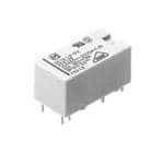
ICGOO电子元器件商城为您提供DE1A-L2-5V由Panasonic Corporation设计生产,在icgoo商城现货销售,并且可以通过原厂、代理商等渠道进行代购。 DE1A-L2-5V价格参考。Panasonic CorporationDE1A-L2-5V封装/规格:功率继电器,高于 2 A, 通用 继电器 SPST-NO(1 Form A) 5VDC 线圈 通孔。您可以下载DE1A-L2-5V参考资料、Datasheet数据手册功能说明书,资料中有DE1A-L2-5V 详细功能的应用电路图电压和使用方法及教程。
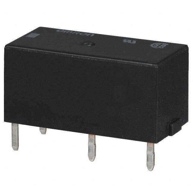
Panasonic Electric Works的DE1A-L2-5V是一款功率继电器,额定电流高于2A,广泛应用于需要中高功率控制的场合。该继电器线圈电压为5V DC,具备良好的稳定性和耐用性,适用于工业自动化、家电控制、电源管理和安防系统等领域。

在工业设备中,DE1A-L2-5V可用于控制电机、电磁阀或加热元件的通断,实现自动化流程中的电气隔离和负载切换。在智能家电中,如电热水器、空调或洗衣机中,它可用来控制大功率部件的运行,确保系统的安全与可靠。

此外,该继电器也适用于直流电源系统,例如太阳能逆变器或储能系统中,用于切换电池回路或负载线路。其高耐压和强抗干扰能力使其在复杂的电磁环境中依然表现稳定。

总之,DE1A-L2-5V凭借其高性能和可靠性,适合用于各类要求较高的电力控制场景。
| 参数 | 数值 |
| 产品目录 | |
| 描述 | RELAY GEN PURPOSE SPST 10A 5V |
| 产品分类 | |
| 品牌 | Panasonic Electric Works |
| 数据手册 | |
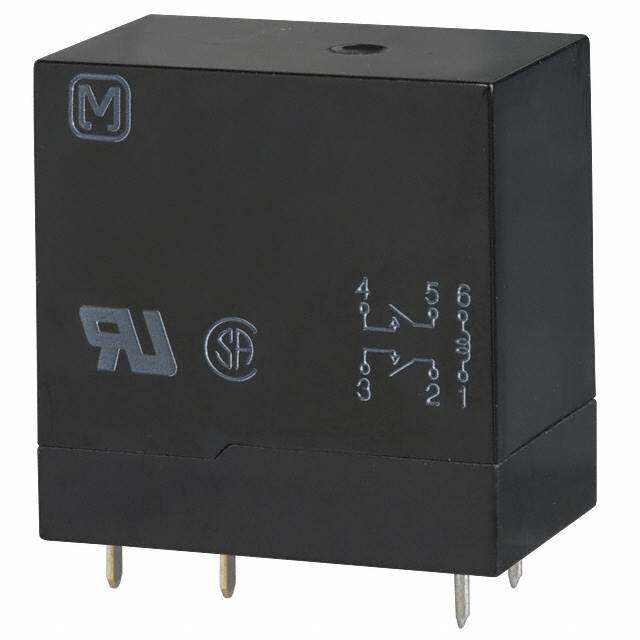
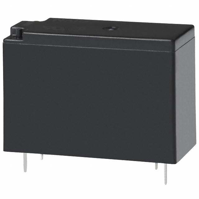
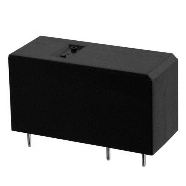
| 产品图片 |
|
| 产品型号 | DE1A-L2-5V |
| rohs | 无铅 / 符合限制有害物质指令(RoHS)规范要求 |
| 产品系列 | DE |
| 关闭电压(最小值) | - |
| 其它名称 | 255-4034-5 |
| 其它有关文件 | |
| 包装 | 管件 |
| 安装类型 | 通孔 |
| 导通电压(最大值) | 3.5 VDC |
| 工作时间 | 10ms |
| 工作温度 | -40°C ~ 70°C |
| 开关电压 | 250VAC,30VDC - 最小值 |
| 标准包装 | 50 |
| 特性 | - |
| 端子类型 | PC 引脚 |
| 线圈功率 | 200 mW |
| 线圈电压 | 5VDC |
| 线圈电流 | 40mA |
| 线圈电阻 | 125 欧姆 |
| 线圈类型 | 锁存,双线圈 |
| 继电器类型 | 通用 |
| 触头外形 | SPST-NO(1 A 型) |
| 触头材料 | 银锡氧化物(AgSnO) |
| 释放时间 | 5ms |
| 额定接触(电流) | 10A |


PDF Datasheet 数据手册内容提取
Compliant with European standards DE RELAYS 1a/2a/1a1b 10A/8A polarized power relays FEATURES TYPICAL APPLICATIONS 1. Conforms to European safety 1. Temperature controller standard (VDE0700 and VDE0631) 2. Automatic meter reading Insulating distance between coil and 3. OA equipment contacts: 4. FA equipment Clearance Min. 8mm .315 inch Creepage Min. 8mm .315 inch 2. Low operating power Nominal operating power at 200 mW RoHS compliant (Single side stable, 2 coil latching) 3. Compact body saves space Size: 12.5(W) × 25(L) × 12.5(H) mm Protective construction: Sealed type .492(W) × .984(L) × .492(H) inch 4. Conforms to the various safety standards UL, C-UL and VDE approved ORDERING INFORMATION DE Contact arrangement 1a: 1 Form A 2a: 2 Form A 1a1b:1 Form A 1 Form B Operating function Nil:Single side stable L2:2 coil latching Nominal coil voltage (DC) 5, 12, 24V Note: This product is manufactured by lot after an order is received. TYPES Part No. Contact arrangement Nominal coil voltage Single side stable type 2 coil latching type 5V DC DE1a-5V DE1a-L2-5V 1 Form A 12V DC DE1a-12V DE1a-L2-12V 24V DC DE1a-24V DE1a-L2-24V 5V DC DE1a1b-5V DE1a1b-L2-5V 1 Form A 1 Form B 12V DC DE1a1b-12V DE1a1b-L2-12V 24V DC DE1a1b-24V DE1a1b-L2-24V 5V DC DE2a-5V DE2a-L2-5V 2 Form A 12V DC DE2a-12V DE2a-L2-12V 24V DC DE2a-24V DE2a-L2-24V Standard packing: Tube package: 20 pcs.; Case: 500 pcs. Note:This product is manufactured by lot after an order is received. –1– ASCTB175E 201612-T
DE RATING 1. Coil data 1) Single side stable type Nominal operating Nominal coil Pick-up voltage Drop-out voltage Coil resistance Nominal operating Max. applied voltage voltage (at 20°C 68°F) (at 20°C 68°F) [±10%] c(autr r2e0n°tC 68°F) [±10%] (at 20°C 68°F) power (at 20°C 68°F) 5V DC 70%V or less of 10%V or more of 40 mA 125Ω 12V DC nominal voltage nominal voltage 16.6mA 720Ω 200mW 130%V of nominal voltage 24V DC (Initial) (Initial) 8.3mA 2,880Ω 2) 2 coil latching type Nominal operating Coil resistance Nominal operating Novmoilntaagl ecoil (aSt e2t0 v°Col t6a8g°eF ) (Raet s2e0t° Cvo 6lt8a°gFe) [±10%] c(autr r2e0n°tC 68°F) [±10%] (at 20°C 68°F) power Ma(xa. ta 2p0p°liCe d6 8vo°Flt)age Set coil Reset coil Set coil Reset coil Set coil Reset coil 5V DC 70%V or less of 70%V or less of 40 mA 40 mA 125Ω 125Ω 12V DC nominal voltage nominal voltage 16.6mA 16.6mA 720Ω 720Ω 200mW 200mW 130%V of nominal voltage 24V DC (Initial) (Initial) 8.3mA 8.3mA 2,880Ω 2,880Ω 2. Specifications Characteristics Item Specifications Arrangement 1 Form A 1 Form A 1 Form B 2 Form A Contact Contact resistance (Initial) Max. 30 mΩ (By voltage drop 6 V DC 1A) Contact material AgSnO2 type Nominal switching capacity (resistive load) 10A 250V AC, 10A 30V DC 8A 250V AC, 8A 30V DC Max. switching power (resistive load) 2,500VA, 300W 2,000VA, 240W Rating Max. switching voltage 250V AC, 30V DC 250V AC, 30V DC Max. switching current 10A 8A Min. switching capacity*1 100mA 5V DC Insulation resistance (Initial) Min. 1,000MΩ (at 500V DC) Measurement at same location as “Breakdown voltage” section. Between open contacts 1,000 Vrms for 1 min. (Detection current: 10 mA) Breakdown voltage Between contact sets — 4,000 Vrms for 1 min. (Detection current: 10 mA) (Initial) Between contact and coil 5,000 Vrms for 1 min. (Detection current: 10 mA) Electrical Surge breakdown voltage*2 characteristics (Between contact and coil) 12,000 V (Initial) Operate time [Set time] (at 20°C 68°F) Max. 10 ms [Max. 10 ms] (Nominal coil voltage applied to the coil, excluding contact bounce time.) Release time [Reset time] (at 20°C 68°F) Max. 5 ms [Max. 10 ms] (Nominal coil voltage applied to the coil, excluding contact bounce time.) (without diode) Functional Min. 196 m/s2 (Half-wave pulse of sine wave: 11 ms; detection time: 10μs.) Shock resistance Mechanical Destructive Min. 980 m/s2 (Half-wave pulse of sine wave: 6 ms.) characteristics Functional 10 to 55 Hz at double amplitude of 2 mm (Detection time: 10μs.) Vibration resistance Destructive 10 to 55 Hz at double amplitude of 3 mm Expected life Mechanical Min. 107 (at 300 times/min.) Conditions for operation, transport and Ambient temperature: –40°C to +70°C –40°F to +158°F; Conditions storage*3 *4 Humidity: 5 to 85% R.H. (Not freezing and condensing at low temperature) Unit weight Approx. 7 g .25 oz Notes:*1.This value can change due to the switching frequency, environmental conditions, and desired reliability level, therefore it is recommended to check this with the actual load. *2.Wave is standard shock voltage of ±1.2×50μs according to JEC-212-1981 *3.The upper limit of the ambient temperature is the maximum temperature that can satisfy the coil temperature rise value. Refer to Usage, transport and storage conditions in NOTES. *4.Allowable temperature range with our package form: –40°C to +60°C –40°F to +140°F. 3. Electrical life Condition: Resistive load, at 20 times/min. Type Switching capacity No. of operations 1 Form A 10A 250V AC min. 1×10⁵ 10A 30V DC 1 Form A 1 Form B 8A 250V AC min. 1×10⁵ 8A 30V DC 8A 250V AC min. 1×10⁵ 2 Form A 8A 30V DC min. 5×10⁴ –2– ASCTB175E 201612-T
DE REFERENCE DATA 1.-(1) Maximum switching power (1 Form A) 1.-(2) Maximum switching power 2.-(1) Life curve (1 Form A) (1 Form A 1 Form B, 2 Form A) 100 100 100 50 Contact current, A10 DC resistive loaAdC resistive load Contact current, A10 DC resistive loadAC resistive load ×4Life, 10 10 3205 0V V D ACC r eressisistitvieve l oloaadd 1 1 0.1 0.1 1 10 100 1000 1 10 100 1000 0 1 2 3 4 5 6 7 8 9 10 Contact voltage, V Contact voltage, V Contact current, A 2.-(2) Life curve (1 Form A 1 Form B) 2.-(3) Life curve (2 Form A) 3.-(1) Coil temperature rise (1 Form A) Tested sample: DE1a-5V Quantity: n=6 Ambient temperature: 25°C to 70°C 77°F to 158°F 100 100 50 25°C77°F 70°C158°F 50 3205 0V V D ACC r eressisistitvieve l oloaadd 50 250 V AC resistive load °e, C 40 10A ×4Life, 10 10 ×4Life, 10 10 perature ris30 001AA0A m Te 20 30 V DC resistive load 10 0 0 1 2 3 4 5 6 7 8 9 10 0 1 2 3 4 5 6 7 8 9 10 70 80 90 100 110 120 130 Contact current, A Contact current, A Coil applied voltage, %V 3.-(2) Coil temperature rise (1 Form A 1 Form B) 3.-(3) Coil temperature rise (2 Form A) 4.-(1) Operate/release time (1 Form A) Tested sample: DE1a1b-5V Tested sample: DE2a-5V Tested sample: DE1a-5V Quantity: n=6 Quantity: n=6 Quantity: n=5 Ambient temperature: 25°C to 70°C 77°F to 158°F Ambient temperature: 25°C to 70°C 77°F to 158°F 50 50 9 25°C77°F 25°C77°F °Temperature rise, C324000 70°C158°F 0088AAAA °Temperature rise, C324000 70°C158°F 0088AAAA Operate/release time, ms 876543 Operate time MMMMxxaaiinnxx.... 10 10 2 Release time (With diode) Max. 1 x Min. Release time 0 0 0 70 80 90 100 110 120 130 70 80 90 100 110 120 130 70 80 90 100 110 120 130 Coil applied voltage, %V Coil applied voltage, %V Coil applied voltage, %V 4.-(2) Operate/release time (1 Form A 1 Form B) 4.-(3) Operate/release time (2 Form A) 5.-(1) Ambient temperature characteristics Tested sample: DE1a1b-5V, Quantity: n=5 Tested sample: DE2a-5V, Quantity: n=5 (1 Form A) Tested sample: DE1a-5V, Ambient temperature: –40°C to 80°C –40°F to 176°F, Quantity: n=6 7 8 Release time % perate/release time, ms 6543 Opera(Wtei tthim deiode) MMMMMxxxiaaainnxxx..... perate/release time, ms 76543 Operate timeMMxianxM.xM.ina.x. ––4400 ––240 302–Rate of change, V10 12326008000Dv14o0r04lotapg-o1e64u00tPvoic1l8t7ka06-guep O 2 Min. O 2 R(Weilteha dseio dtime)e –20 Atemmbpieernatture,°C°F Max. 1 Release time 1 Mxin. –30 Release time 0 0 70 80 90 100 110 120 130 70 80 90 100 110 120 130 Coil applied voltage, %V Coil applied voltage, %V –3– ASCTB175E 201612-T
DE 5.-(2) Ambient temperature characteristics 5.-(3) Ambient temperature characteristics (1 Form A 1 Form B) (2 Form A) Tested sample: DE1a1b-5V, Ambient temperature: Tested sample: DE2a-5V, Ambient temperature: –40°C to 80°C –40°F to 176°F, Quantity: n=6 –40°C to 80°C –40°F to 176°F, Quantity: n=6 % % Rate of change, V 1230000 Dvorlotapg-oeut Pvoicltka-guep Rate of change, V 1230000Dvorlotapg-oeut Pvoicltka-guep –40 –20 0 20 40 60 80 –40 –20 0 20 40 60 80 –40 –4 32 68104 140 176 –40 –4 32 68104 140 176 –10 –10 Ambient Ambient temperature,°C°F temperature,°C°F –20 –20 –30 –30 DIMENSIONS (mm inch) The CAD data of the products with a CAD Data mark can be downloaded from: http://industrial.panasonic.com/ac/e/ CAD Data External dimensions PC board pattern (Bottom view) Single side stable type Single side stable type 2 coil latching type 25.00 12.50 6-1.2 dia. 8-1.2 dia. .984 .492 15.24 7.62 6-.047 dia. 2.54 12.70 7.62 8-.047 dia. .600 .300 .100 .500 .300 12.4.5902 0.0.5200 .73.0620 7.3.6020 3.50 .138 22--0.0.5200 ddiiaa.. 44--0.0.8302 44--0.0.4106 Tolerance : ±0.1 ±.004 7.62 1.15 15.24 7.62 .300 Schematic (Bottom view) .045 .600 .300 Single side stable type (1 Form A) (1 Form A 1 Form B) (2 Form A) 2 coil latching type 1 3 4 1 3 4 1 3 4 25.00 12.50 .984 .492 8 6 5 8 6 5 8 6 5 12.50 0.50 (5,6: dummy terminal) (Deenergized condition) .492 .020 2coil latching type 3.50 (1 Form A) (1 Form A 1 Form B) (2 Form A) .138 4-0.80 1 2 3 4 1 2 3 4 1 2 3 4 44--0.0.5200 ddiiaa.. 4-.032 44--0.0.4106 1.15 12.70 7.62 7.62 8 7 6 5 8 7 6 5 8 7 6 5 .045 .500 .300 .300 2.54 (5,6: dummy terminal) (Reset condition) .100 Tolerance: ±0.3 ±.012 –4– ASCTB175E 201612-T
DE SAFETY STANDARDS UL/C-UL (Recognized) VDE (Certified) Types File No. Contact rating Cycles File No. Contact rating Temperature Cycles 8A 120V AC Lamp Load 3 × 10⁴ 8A 250V AC (cosφ=1.0) 70°C 158°F 15 × 104 12A 120V AC General use 3 × 10⁴ 16A 250V AC (cosφ=1.0) 70°C 158°F 6 × 10³ 8A 277V AC General use – – – – 10A 277V AC Ballast – – – – 1 Form A E120782 115944 2A 480V AC Resistive 105 – – – 1HP 277V AC – – – – 6A 347V AC General use 3 × 10⁴ – – – PILOT DUTY B300,R300 – – – – 6A 120V AC Lamp Load 3 × 10⁴ 8A 250V AC (cosφ=1.0) 70°C 158°F 15 × 104 8.5A 120V AC General use 3 × 10⁴ 16A 250V AC (cosφ=1.0) 70°C 158°F 5 × 10³ 6A 277V AC General use 3 × 10⁴ – – – 1 Form A 1 Form B E120782 2A 480V AC Resistive 105 115944 – – – 0.7HP 277V AC – – – – 4.5A 347V AC General use 3 × 10⁴ – – – PILOT DUTY B300,R300 – – – – 8A 120V AC Lamp Load 3 × 10⁴ 8A 250V AC (cosφ=1.0) 70°C 158°F – 12A 120V AC General use 3 × 10⁴ – – – 8A 277V AC General use – – – – 10A 277V AC Ballast – – – – 2 Form A E120782 115944 2A 480V AC Resistive 105 – – – 1HP 277V AC – – – – 6A 347V AC General use 3 × 10⁴ – – – PILOT DUTY B300,R300 – – – – *CSA standard: Certified by C-UL EN/IEC VDE Certified INSULATION CHARACTERISTICS (IEC61810-1) Item Characteristics Clearance/Creepage distance (IEC61810-1) Min. 8.0/8.0mm Category of protection (IEC61810-1) RT III Tracking resistance (IEC60112) PTI 175 Insulation material group III a Over voltage category III Rated voltage 250V Pollution degree 3 Type of insulation (Between contact and coil) Reinforced insulation Type of insulation (Between open contacts) Micro disconnection NOTES 1. For cautions for use, please read “GENERAL APPLICATION GUIDELINES”. –5– ASCTB175E 201612-T
None
Mouser Electronics Authorized Distributor Click to View Pricing, Inventory, Delivery & Lifecycle Information: P anasonic: DE2A-3V DE1A1B-L-5V DE1a-12V DE1a1b-12V DE1a1b-24V DE1a1b-5V DE1a1b-L2-12V DE1a1b-L2-24V DE1a1b-L2-5V DE1a-24V DE1a-5V DE1a-L2-12V DE1a-L2-24V DE1a-L2-5V DE2a-12V DE2a-24V DE2a-5V DE2a-L2-12V DE2a-L2-24V DE2a-L2-5V DE1A1B-3V DE1A1B-4.5V DE1A1B-48V DE1A1B-6V DE1A1B-9V DE1A1B-L-12V DE1A1B-L2-3V DE1A1B-L2-4.5V DE1A1B-L-24V DE1A1B-L2-6V DE1A1B-L2-9V DE1A1B-L-3V DE1A1B-L-4.5V DE1A1B-L-6V DE1A1B-L-9V DE1A-3V DE1A-4.5V DE1A-48V DE1A-6V DE1A-9V DE1A-L-12V DE1A-L2-4.5V DE1A-L-24V DE1A-L2-6V DE1A-L2-9V DE1A-L-4.5V DE1A-L-5V DE1A-L-6V DE1A-L-9V DE2A- 48V DE2A-6V DE2A-L-12V DE2A-L2-3V DE2A-L2-4.5V DE2A-L-24V DE2A-L2-6V DE2A-L2-9V DE2A-L-3V DE2A-L-4.5V DE2A-L-5V DE2A-L-6V DE2A-L-9V