ICGOO在线商城 > 连接器,互连器件 > D-Sub,D 形连接器 - 外壳 > DBUH-25P-FO
 Datasheet下载
- 型号: DBUH-25P-FO
- 制造商: Cinch
- 库位|库存: xxxx|xxxx
- 要求:
| 数量阶梯 | 香港交货 | 国内含税 |
| +xxxx | $xxxx | ¥xxxx |
查看当月历史价格
查看今年历史价格
DBUH-25P-FO产品简介:
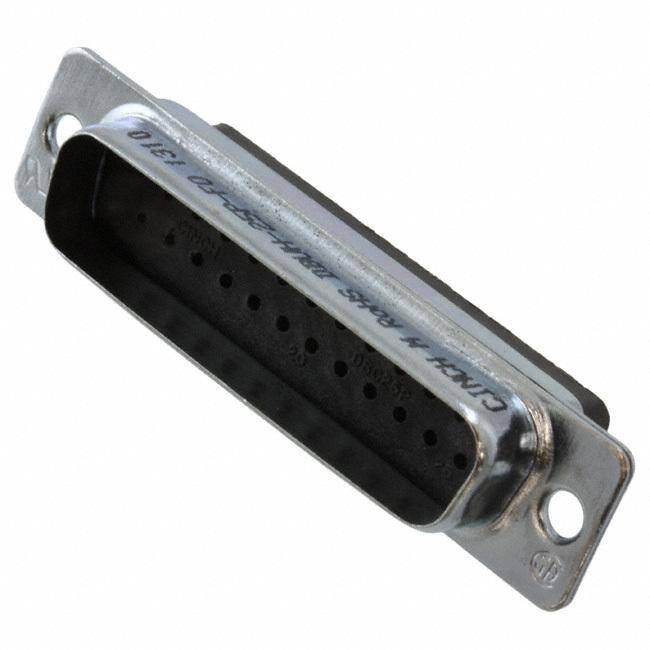
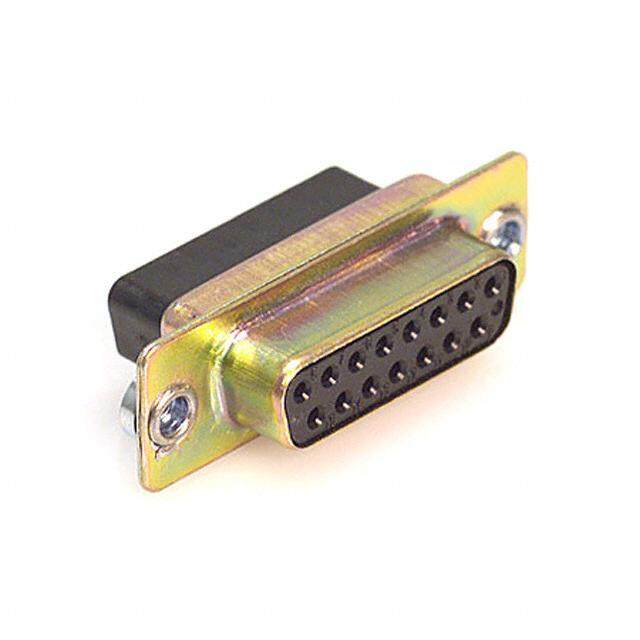
ICGOO电子元器件商城为您提供DBUH-25P-FO由Cinch设计生产,在icgoo商城现货销售,并且可以通过原厂、代理商等渠道进行代购。 DBUH-25P-FO价格参考。CinchDBUH-25P-FO封装/规格:D-Sub,D 形连接器 - 外壳, Plug for Male Contacts Housing D-Sub Connector 25 Position。您可以下载DBUH-25P-FO参考资料、Datasheet数据手册功能说明书,资料中有DBUH-25P-FO 详细功能的应用电路图电压和使用方法及教程。
Cinch Connectivity Solutions品牌的DBUH-25P-FO型号属于D-Sub系列的D形连接器外壳,广泛应用于需要可靠信号传输和坚固机械性能的场景。以下是其主要应用场景:

 1. 工业自动化
   - 用于工业控制设备中的数据传输,如PLC(可编程逻辑控制器)、传感器接口和人机界面(HMI)。
   - 提供高可靠性连接,适应恶劣环境条件,如振动、灰尘和湿度。

 2. 通信设备
   - 在路由器、交换机和其他网络设备中作为信号接口,支持串行通信协议(如RS-232、RS-485等)。
   - 适用于需要稳定连接的远程通信场景。

 3. 医疗设备
   - 用于诊断设备、监护仪和医疗成像系统中的信号传输。
   - 确保关键医疗数据的准确性和稳定性。

 4. 军事与航空航天
   - 在军工设备和航空电子系统中提供可靠的电气连接。
   - 能够承受极端温度和高强度振动,满足严苛的军用标准。

 5. 测试与测量
   - 应用于示波器、信号发生器和数据采集系统中,确保精确的数据传输。
   - 支持多种测试环境下的高效连接需求。

 6. 计算机与外围设备
   - 用于早期计算机的串口、并口连接,以及打印机、扫描仪等外设接口。
   - 尽管现代USB接口逐渐取代了D-Sub,但在某些老旧系统中仍被广泛使用。

 7. 交通运输
   - 在列车控制系统、车载导航和监控系统中提供稳定的信号连接。
   - 抗震性能强,适合动态运行环境。

 总结
DBUH-25P-FO连接器以其坚固耐用的设计、广泛的引脚配置和出色的电气性能,成为许多关键领域中不可或缺的组件。它特别适合需要高可靠性、长寿命和抗干扰能力的应用场景。
| 参数 | 数值 |
| 产品目录 | |
| 描述 | CONN DB25 PLUG CRIMP W/O CONTD-Sub标准连接器 25C PLG NO CONTACTS D*U SERIES |
| 产品分类 | |
| 品牌 | Cinch |
| 产品手册 | http://www.cinch.com/products/d-subminiature/crimp-poke-du-series-metal-shell |
| 产品图片 |
|
| rohs | 符合RoHS无铅 / 符合限制有害物质指令(RoHS)规范要求 |
| 产品系列 | D-Sub标准连接器,Cinch DBUH-25P-FOD*U |
| 数据手册 | |
| 产品型号 | DBUH-25P-FO |
| 产品种类 | D-Sub标准连接器 |
| 介电材料 | 聚酰胺(PA),尼龙,玻璃纤维增强型 |
| 位置数量 | 25 |
| 侵入防护 | - |
| 其它名称 | 116-1018 |
| 包装 | 散装 |
| 商标 | Cinch |
| 型式 | Male |
| 备注 | 不提供触点 |
| 外壳大小 | B |
| 外壳尺寸,连接器布局 | 3(DB,B) |
| 外壳材料,镀层 | 钢,纯色铬酸锌电镀 |
| 外壳材质 | Steel |
| 外壳电镀 | Zinc |
| 外壳镀层厚度 | - |
| 安装类型 | 自由悬挂 |
| 安装角 | Straight |
| 安装风格 | Wire |
| 工作温度 | -65°C ~ 125°C |
| 工作温度范围 | - 65 C to + 125 C |
| 工厂包装数量 | 750 |
| 排数 | 2 |
| 标准包装 | 750 |
| 法兰特性 | 体座/外壳(无螺纹) |
| 特性 | - |
| 电流额定值 | 5 A |
| 相关产品 | /product-detail/zh/030-1952-030/030-1952-030-ND/3602462/product-detail/zh/030-1952-000/116-1000-ND/3602461/product-detail/zh/DCH-B-003/116-1020-ND/1278692/product-detail/zh/DB-24659-32/116-1014-ND/1278677/product-detail/zh/DB-19977-32/DB-19977-32-ND/1278676 |
| 端接类型 | Crimp |
| 触头类型 | 信号 |
| 触点材料 | Copper Alloy |
| 触点电镀 | Gold |
| 连接器样式 | D-Sub |
| 连接器类型 | 公触点插头 |
| 配套产品 | /product-detail/zh/DBUH-25S/DBUH-25S-ND/1278687/product-detail/zh/DBUH-25S-FO/116-1019-ND/1278684 |
| 配接次数 | 500 |
| 针脚数 | 25 |
| 颜色 | 黑 |


PDF Datasheet 数据手册内容提取
D-SUBMINIATURE D*KL Series HTD/HPD Series D*A Series Overmold Kits D*U Series T* Series Basic D Series Series 1 - High Reliability Series 3 - High Reliability M24308 Series Backshells/Junctionshells/Hoods Accessories Application Tooling
The D-subminiature is one of the most popular styles of connectors in the I/O category. It is used in computer, telecom, datacom, medical, and test instrumentation applications as well as in the military and aerospace fields. Types of D-subminiature connectors manufactured by Cinch • Printed Circuit Board connectors: - Vertical connectors for panel mounting with Dip Solder PCtails. - Right-Angle connectors for board mounting with Dip Solder PC tails. • Wire Termination connectors for cable assemblies or wire harnesses: - Crimp and Poke connectors. - Solder Cup connectors. - Insulation Displacement connectors IDC to terminate discrete wire or flat cable. S - Wire Wrap connectors. How to read this section • The information pages provide standard data common to all D-subminiature connectors. These include: - D-subminiature contact arrangements - see page 4-5. - Panel mounting specifications/hardware - see page 4-6. - D-subminiature shell dimensions - see page 4-7. - D-subminiature and combo D layouts - see pages 4-5, 4-8 thru 4-10, and 4-56. - General Performance Specifications - see page 4-2. - PCBthickness chart - see page 4-8. • D-subminiature pages are grouped by series. A series is a family of connectors with a similar performance level. Each series shares a set of features and specifications, from economical and commercial grade product to high-reliability and military connectors. Each series begins with a page outlining general features and specifications of connectors, followed by the pages on individual connectors with drawings or features specific to that connector. Drawings reflect clarifications of dimensions not called out in the information pages of this catalog. The features of each series can be found in the chart on page 4-4. • Accessories including backshells, junction shells, and hoods as well as hardware can be found on pages 4-80 thru 4-99. • Termination tooling for Cinch connectors can be found at the end of the D-subminiature section of this catalog on pages 4-100 thru 4-104. 4-1 Call Toll Free: 1 (800) 323-9612
General Information • All connectors are intermateable with any Cinch D-subminiature of comparable pin count and density, or the D-sub connector of any other manufacturer complying dimensionally with MIL-C-24308. • Solder terminations and boardlocks meet the requirements for solderability in accordance with MIL-STD-202, Method 208. • DURABILITY - Mated connectors are subjected to cycles of insertions and withdrawals specified on the catalog page. After the prescribed cycles the connectors will meet the Cinch requirements concerning insertion- withdrawal force, individual contact insertion-withdrawal force, and contact resistance. • APPROVALS - Most Cinch connectors have UL recognition and CSA approval;however, the specific approvals are listed on the individual catalog pages. • CONTACTS - Cinch connector contacts are generally offered in Gold Flash or 30µin.gold plating for commercial product, and 50µin.gold plating for M24308 Series Military D-subminiature connectors. - Cinch connectors utilize economical stamped and formed contacts and/or screw machine contacts for enhanced performance. - Standard density connectors utilize size 20 contacts. - Cinch 1.5 Density Series connectors utilize size 22 contacts for greater density in a standard size D-subminiature outer shell. • METAL SHELLS - Commercial-grade steel shells are usually available in zinc plating with yellow chromate finish or tin plating. - Tin-plated plugs have grounding indents. - Military grade M24308 Series connector shells are generally steel or in certain cases non-magnetic brass with cadmium plating and yellow chromate finish. - Insulator materials are glass-filled polyester, glass-filled nylon, and diallyl phthalate. • The connectors are usually available in plugs and sockets in 9, 15, 25, 37, and 50 position sizes. Call Toll Free: 1 (800) 323-9612 4-2
Printed Circuit Board Connectors • Cinch provides connectors in various footprints, contact diameters, and lengths in both vertical and right-angle PCmount styles with dip solder tails. • Cinch PCBconnectors have metal shells. Connectors for Terminating Cable Wire • Wire Wrap connectors are available in two tail lengths for two-wrap and three-wrap terminations. The contact is terminated by wrapping wire around it using a wire wrap gun. This connector is especially useful for prototyping since the wire can be unwrapped and rewrapped if necessary. • Solder Cup connectors allow reliable long-term termination by soldering the wire directly into the connector contact. Cinch Solder Cups accommodate up to 20 AWG wire. • Crimp and Poke connectors allow the wire to be terminated more economically than wire wrap or solder cup styles. Contacts are crimped and inserted into the connector. In our D*U Series, the contact is crimped around the conductor wire. In our D*A Series, the contact is crimped around the wire and the insulation. Crimp and Poke connectors can be selectively loaded to save labor and material cost. • IDC connectors are an alternative to other types of wire termination connectors. IDC is much faster and very reliable when all contacts are terminated and the volume is high. IDCutilizes mass termination of the cable wire. This can save considerable time and expense in the cable assembly process. The estimated time of terminating two ends of a 25-conductor discrete wire cable with 25-position D-subminiature connectors is about 5-1/2 to 6 minutes less per cable assembly using IDC connectors and Cinch Auto-Clinch termination tooling versus using Crimp and Poke connectors. This may vary considerably based on the operator, cable wire, and process. Cinch offers IDC connectors in two versions-for discrete wire or flat ribbon termination. 4-3 Call Toll Free: 1 (800) 323-9612
Feature Guide The chart below contains CinchD-subminiature product features and styles grouped by series. Performance Level Economical Commercial High-Reliability Military Series D*KL HPD/HTD D*A D*U T Basic D Series 1 Series 3 M24308 Termination Type • Vertical PCB 4-12 4-26 4-42 4-50 4-76 • Right-Angle PCB 4-12 4-16 4-26 4-50 4-76 • Crimp and Poke 4-16 4-20 4-26 4-72 4-76 • Solder Cup 4-34 4-42 4-50 4-76 • IDC 4-34 • Wire Wrap 4-42 Insulator Material • • G-F Nylon • • • • G-F Polyester • • • Diallyl Phthalate Shell Material • All Plastic • • • • • • • • • Steel Shell Shell Plating • • • • • • • • Tin-Lead Plating • • • • • • Zinc Plating-Y/C finish •* • • Cadmium Plating-Y/C finish Contact Plating • • • • • • Gold-Flash Plating • • • • • • • • 30µin.Gold Plating •* • • 50µin.Gold Plating Contact Type • • • • • • Stamped Contacts • • • • • Machined Contacts Accessories information starts on page 4-80. Tooling information starts on page 4-100. * Applies to Combination Layout Only. Call Toll Free: 1 (800) 323-9612 4-4
Standard Density Plug Inserts NOTE: Mating face of plug is shown;socket is mirror image. 4-5 Call Toll Free: 1 (800) 323-9612
Panel Mounting Specifications Dimensions Mounting Method Shell Front/ A B C D E F H Size Positions Rear Panel in mm in mm in mm in mm in mm in mm in mm Front 0.98 24.89 0.49 12.45 0.87 22.10 0.44 11.18 0.51 12.95 0.26 6.60 0.08 2.03 E 9 Rear 0.98 24.89 0.49 12.45 0.81 20.57 0.40 10.16 0.45 11.43 0.23 5.84 0.13 3.30 Front 1.31 33.27 0.66 16.76 1.10 27.94 0.60 15.24 0.51 12.95 0.26 6.60 0.08 2.03 A 15 Rear 1.31 33.27 0.66 16.76 1.13 28.70 0.57 14.48 0.45 11.43 0.23 5.84 0.13 3.30 Front 1.85 46.99 0.93 23.62 1.74 44.20 0.87 22.10 0.51 12.95 0.26 6.60 0.08 2.03 B 25 Rear 1.85 46.99 0.93 23.62 1.67 42.42 0.84 21.34 0.45 11.43 0.23 5.84 0.13 3.30 Front 2.50 63.50 1.25 31.75 2.39 60.71 1.20 30.48 0.51 12.95 0.26 6.60 0.08 2.03 C 37 Rear 2.50 63.50 1.25 31.75 2.33 59.18 1.16 29.46 0.45 11.43 0.23 5.84 0.13 3.30 Front 2.41 61.21 1.20 30.48 2.30 58.42 1.15 29.21 0.62 15.75 0.31 6.60 0.08 2.03 D 50 Rear 2.41 61.21 1.20 30.48 2.22 56.39 1.11 28.19 0.56 14.22 0.28 5.84 0.13 3.30 PANEL MOUNTING HARDWARE: Aids in alignment of plug and receptacle. Float Bushing Reverse Float Bushing Rear panel mounting Front panel mounting Floating Dual Bushing 4-40 Clinch Nut Rear panel mounting Front and rear panel mounting Call Toll Free: 1 (800) 323-9612 4-6
Two Holes .120 +.005 (3.05 +0.13) Dia. Mating Side Termination Side A +.015" B +.010" B1 +.005" C +.005" D +.010" D1 +.010" E +.010" Shell Connector (0.38mm) (0.25mm) (0.13 mm) (0.13mm) (0.25mm) (0.25mm) (0.25mm) Size Positions Type in mm in mm in mm in mm in mm in mm in mm E 9 Plug 1.213 30.81 -- -- .666 16.90 0.984 24.99 -- -- .329 8.40 .494 12.55 Socket 1.213 30.81 .640 16.26 -- -- 0.984 24.99 .308 7.82 -- -- .494 12.55 A 15 Plug 1.541 39.14 -- --- .994 25.30 1.312 33.32 -- --- .329 8.40 .494 12.55 Socket 1.541 39.14 .968 24.59 -- -- 1.312 33.32 .308 7.82 -- -- .494 12.55 B 25 Plug 2.088 53.04 -- -- 1.534 39.00 1.852 47.04 -- -- .329 8.40 .494 12.55 Socket 2.088 53.04 1.508 38.30 -- -- 1.852 47.04 .308 7.82 -- -- .494 12.55 C 37 Plug 2.729 69.32 -- --- 2.182 55.40 2.500 63.50 -- --- .329 8.40 .494 12.55 Socket 2.729 69.32 2.156 54.76 -- -- 2.500 63.50 .308 7.82 -- --- .494 12.55 D 50 Plug 2.635 66.93 -- -- 2.079 52.80 2.406 61.11 -- -- .436 11.07 .605 15.37 Socket 2.635 66.93 2.062 52.34 -- -- 2.406 61.11 .420 10.67 -- -- .605 15.37 G +.010" H +.010" J +.010" K +.005" L +.010" M +.010" Shell Connector (0.25mm) (0.25mm) (0.25 mm) (0.25mm) (0.25mm) (0.25mm) Size Positions Type in mm in mm in mm in mm in mm in mm E 9 Plug .759 19.28 .422 10.72 .030 0.76 .236 5.99 .045 1.14 .422 10.72 Socket .759 19.28 .422 10.72 .030 0.76 .243 6.17 .045 1.14 .429 10.92 A 15 Plug 1.083 27.51 .422 10.72 .030 0.76 .236 5.99 .045 1.14 .422 10.72 Socket 1.083 27.51 .422 10.72 .030 0.76 .253 6.17 .045 1.14 .429 10.92 B 25 Plug 1.625 41.27 .422 10.72 .039 0.99 .231 5.87 .060 1.52 .426 10.82 Socket 1.625 41.27 .422 10.72 .030 0.76 .243 6.17 .045 1.14 .429 10.92 C 37 Plug 2.272 57.71 .422 10.72 .039 0.99 .231 5.87 .060 1.52 .426 10.82 Socket 2.272 57.71 .422 10.72 .030 0.76 .243 6.17 .045 1.14 .429 10.92 D 50 Plug 2.178 55.32 .534 13.56 .039 0.99 .231 5.87 .060 1.52 .426 10.82 Socket 2.178 55.32 .534 13.56 .030 0.76 .243 6.17 .045 1.14 .429 10.92 B and D are outside dimensions for socket. D and B are inside dimensions for plug. 4-7 Call Toll Free: 1 (800) 323-9612
Standard Density D-subminiature Mounting Dimensions Board Layouts Footprints (Component side shown) 9 Position Shell Size E 25 Position Shell Size B 15 Position Shell Size A PCBoard Lead Hole Size The footprints on this page are standard for all metal shell D-subminiature connectors. Terminal Dia. Hole Dia. in mm in mm On all right-angle D-subminiature connectors, the .040 1.02 .055 1.40 short row of contacts is positioned closest to the .030 0.76 .045 1.14 .024-.025 0.61-0.64 .039 0.99 edge of the board. Call Toll Free: 1 (800) 323-9612 4-8
Standard Density D-subminiature Mounting Dimensions Board Layouts Footprints (Component side shown) 37 Position 50 Position Shell Size C Shell Size D PCBoard Lead Hole Size The footprints on this page are standard for all metal shell D-subminiature connectors. Terminal Dia. Hole Dia. in mm in mm On all right-angle D-subminiature connectors, the .040 1.02 .055 1.40 short row of contacts is positioned closest to the .030 0.76 .045 1.14 .024-.025 0.61-0.64 .039 0.99 edge of the board. 4-9 Call Toll Free: 1 (800) 323-9612
1.5 Density D-subminiature Recommended PCBLayout for Footprint (Component side shown) ) 15 Position 44 Position Shell Size E Shell Size B 26 Position 62 Position Shell Size A Shell Size C PCBoard Lead Hole Size The footprints on this page are standard for all metal shell D-subminiature connectors. Terminal Dia. Hole Dia. in mm in mm On all right-angle D-subminiature connectors, the .040 1.02 .055 1.40 short row of contacts is positioned closest to the .030 0.76 .045 1.14 .024-.025 0.61-0.64 .039 0.99 edge of the board. Call Toll Free: 1 (800) 323-9612 4-10
■ Offered in right-angle or vertical PCB mount versions. ■ Available with gold flash or 30µin.gold plating. ■ Metal Shell provides grounding and shielding capability. ■ Approvals: • ULRecognized: File E130965. • CSAApproved: File LR97981. ■ See pages 4-5 thru 4-10 for standard dimensions,contact arrangements,and panel mounting specifications. Insulator Material: Glass-filled polyester (black), UL 94V-O rated Contact Material: Socket - Phosphor bronze (stamped) Plug - Brass (stamped) Contact Plating: Gold flash or 30µin.gold in mating area and tin/lead on tails. All over nickel. Metal Shell: Steel with tin plating (grounding indents on plug) Operating Temperature: -55°C to +125°C Shock: 50Gpeak per MIL-STD-202, Method 213, Condition G Vibration: 12 cycles in three perpendicular directions @ 10-2000Hz, per MIL-STD-202, Method 204, Condition D Moisture Resistance: 90-95% relative humidity @ 40°C for 96 hours per MIL-STD-202, Method 103 Withstanding Voltage: Right Angle - minimum AC 1250V RMS @ sea level, Vertical - minimum AC 1000V RMS @ sea level Current Rating: 5 Amps Contact Resistance: 15 milliohms maximum Insulation Resistance: 5000 megohms maximum (initial); 1000 megohms (minimum)after environmental testing Individual Contact Insertion and Separation Force (minimum/maximum): 0.7 oz./12 oz. Durability: 500 mating cycles Call Toll Free: 1 (800) 323-9612 4-12
Right-Angle Connectors • 0.318" footprint. • Available in 9, 15, and 25 position plugs and sockets. • Offered with 4-40 threaded inserts for secure mounting to panels or with female screwlocks. • Boardlocks to provide mechanical hold-down during wave soldering process. • Materials: - Boardlock: Brass with tin plating. - Female Screwlock: Brass with nickel plating. Ordering Information Right-Angle Plugs 4-40 Threaded Inserts Female Screwlocks Size Gold Flash 30µin.Gold Gold Flash 30µin.Gold 9 DEKL-9PATI-E DEKL-9PATI-E2 DEKL-9PATI-F DEKL-9PATI-F2 15 DAKL-15PATI-E DAKL-15PATI-E2 DAKL-15PATI-F DAKL-15PATI-F2 25 DBKL-25PATI-E DBKL-25PATI-E2 DBKL-25PATI-F DBKL-25PATI-F2 Right-Angle Sockets 4-40 Threaded Inserts Female Screwlocks Size Gold Flash 30µin.Gold Gold Flash 30µin.Gold 9 DEKL-9SAT-E DEKL-9SAT-E2 DEKL-9SAT-F DEKL-9SAT-F2 15 DAKL-15SAT-E DAKL-15SAT-E2 DAKL-15SAT-F DAKL-15SAT-F2 25 DBKL-25SAT-E DBKL-25SAT-E2 DBKL-25SAT-F DBKL-25SAT-F2 4-13 Call Toll Free: 1 (800) 323-9612
• Vertical Connectors: - Available in 9, 15, 25, 37, and 50 position plugs and sockets with straight dip solder tails. - 0.024" contact diameter. - Offered with standard mounting holes. Plug Ordering Information Vertical PCB Connectors Plugs Sockets Size Gold Flash 30µin.Gold Gold Flash 30µin.Gold 9 DEKL-9PUTI DEKL-9PUTI-2 DEKL-9SUT DEKL-9SUT-2 15 DAKL-15PUTI DAKL-15PUTI-2 DAKL-15SUT DAKL-15SUT-2 25 DBKL-25PUTI DBKL-25PUTI-2 DBKL-25SUT DBKL-25SUT-2 37 DCKL-37PUTI DCKL-37PUTI-2 DCKL-37SUT DCKL-37SUT-2 50 DDKL-50PUTI DDKL-50PUTI-2 DDKL-50SUT DDKL-50SUT-2 Call Toll Free: 1 (800) 323-9612 4-14
■ 1.5 Density means the connector uses small size #22 contacts for a higher pin count in a standard size shell. Also accepts standard D-subminiature accessories (hoods,backshells,etc.) per the following chart: 1.5 D-sub Standard D-sub Shell Size No.of Pins No.of Pins E 15 9 A 26 15 B 44 25 C 62 37 ■ Offered in cable plugs and right-angle PCB mount sockets. ■ Metal Shell provides grounding and shielding capability. ■ Approvals: Plugs: • UL Recognized - Files E170218 (UL1977) & E130965 (UL1863). • CSAApproved - File LR31996-7. Sockets: UL Recognized - File E170218. ■ See pages 4-5 thru 4-10 for standard dimensions,contact arrangements,and panel mounting specifications. Connector Shell: Steel with tin plating (grounding indents on plug) Contact Material: Phosphor bronze (stamped) Contact Plating: • Sockets: Gold flash or 30µin.gold in mating area and tin/lead on tails. All over nickel. • Plugs: Gold flash or 30µin.gold in mating area and gold flash on remainder. All over nickel. Operating Temperature: -55°C to +125°C Shock: 50G peak per MIL-STD-202, Method 213, Condition G Vibration: 12 cycles in three perpendicular directions @10-2000Hz, per MIL-STD-202, Method 204, Condition D Moisture Resistance: 90-95% relative humidity @ 40°C for 96 hours per MlL-STD-202, Method 103 Withstanding Voltage: Minimum 1000V RMS @ sea level Current Rating: 3 Amps Contact Resistance: 15 milliohms maximum Insulation Resistance: 5000 megohms maximum (initial); 1000 megohms (minimum) after environmental testing Individual Contact Insertion and Separation Force (minimum/maximum): 0.7 oz./12 oz. Durability: • Plugs- 200 mating cycles • Sockets- 200 mating cycles Call Toll Free: 1 (800) 323-9612 4-16
Connectors: • Offered with .120 mounting holes. • Shells offered with tin plating and grounding indents. • These connectors are designed to accommodate one repair cycle. Contacts: (Not included with connectors, order separately) • Available with gold-flash plating or 30µin.gold. • Crimp and Poke versions are offered in reels of 15,000 or 300 contacts. • Solder and Poke contacts are packed loose. • Will accommodate 22-30 AWGwire. • Order contacts separately. See page 4-18. Termination Tooling: • Semi-automatic Stripper Crimper Tool for 15,000 reels: #HTD-518. See page 4-102. • Crimp Contact Hand Tool for 300-piece reels: #HTD-266. See page 4-101. • Semi-automatic Hand Crimping Tool for individual contact termination: #HTD-544. See page 4-101. • Contact Insertion/Extraction Tool: Cinch#CIET-22-DF. See page 4-101. Materials: • Insulator Material: Black UL 94 V-0 glass-filled nylon. Ordering Information HTD Series 1.5 Density Crimp and Poke Plug Connectors Size Shell Size Catalog Number 15 E HTDE-15PTI-FO 26 A HTDA-26PTI-FO 44 B HTDB-44PTI-FO 62 C HTDC-62PTI-FO 4-17 Call Toll Free: 1 (800) 323-9612
• Use with HTD Series 1.5 D-Sub Crimp and Poke connectors and overmold kits. • All Crimp and Poke contacts are on right-hand feed reels. Crimp and Poke Plug Contact Solder and Poke Plug Ordering Information HTD Series 1.5 D-sub Male Crimp and Poke and Solder and Poke Contacts Type of Crimp and Poke Crimp and Poke Solder and Poke Packing 15,000 Reel 300 Reel Loose Plating Gold Flash 30µin.Gold Gold Flash 30µin.Gold Gold Flash 30µin.Gold Pin HTD-CP-9-15000 HTD-CP-1-15000 HTD-CP-9-300 HTD-CP-1-300 HTD-SP-9-10 Not Available Call Toll Free: 1 (800) 323-9612 4-18
• .350" footprint. • Offered with fixed 4-40 threaded inserts for secure mounting to panels or with assembled female screwlocks. • Boardlocks to maintain electrical continuity between shell and PCboard ground and provide mechanical hold-down during wave soldering process. • Available in standard configuration sockets, sizes 15, 26, 44, and 62 with black insulator. • 15 position socket also available with royal blue insulator in Windows ‘95®configuration with Pin #9 recessed 0.050". Materials: • Insulator Material: Glass-filled polyester (standard configuration - black, -9R configuration - blue), UL 94V-0 rated. • Boardlock: Brass with tin plating. • Female Screwlock: Brass with Nickel plating. WITH#4-40 FEMALESCREWLOCKS (ASSEMBLED) Dimensions A B C D Positions +.015 (+0.038) +.010 (+0.25) +.010 (+0.25) in mm in mm in mm in mm 15 1.214 30.84 0.984 24.99 0.640 16.26 0.090 2.29 26 1.545 39.24 1.312 33.32 0.967 24.56 0.090 2.29 44 2.088 53.04 1.852 47.04 1.508 38.30 0.090 2.29 62 2.730 69.34 2.500 63.50 2.156 54.76 0.095 2.41 Ordering Information HPD Series 1.5 Density Right-Angle Socket Connectors Shell 4-40 Threaded Inserts Female Screwlocks Size Size Type Color Gold Flash 30µin.Gold Gold Flash 30µin.Gold 15 E Standard Black HPDEB-15SAT-E HPDEB-15SAT-E2 HPDEB-15SAT-F HPDEB-15SAT-F2 26 A Standard Black HPDAB-26SAT-E HPDAB-26SAT-E2 HPDAB-26SAT-F HPDAB-26SAT-F2 44 B Standard Black HPDBB-44SAT-E HPDBB-44SAT-E2 HPDBB-44SAT-F HPDBB-44SAT-F2 62 C Standard Black HPDCB-62SAT-E HPDCB-62SAT-E2 HPDCB-62SAT-F HPDCB-62SAT-F2 15 E Windows ‘95® Blue HPDEB-15SAT-E-9R HPDEB-15SAT-E2-9R HPDEB-15SAT-F-9R HPDEB-15SATF2-9R Windows '95 is a registered trademark of Microsoft. 4-19 Call Toll Free: 1 (800) 323-9612
■ Offered in 9,15 ,25,37,and 50 position plugs and sockets. ■ Contacts: - Available with gold flash or 30µin.gold plating. - Offered in 15,000 contact reel or 300 contact reel,or in loose-piece bags of 100 or 1000 each. - Accommodate 20-24 AWGwire or 26-30 AWGwire. - Not included with connector - order stamped contacts separately. ■ Approvals: - UL Recognized - Files E170218 (UL1977) and E130965 (UL1863). - CSAApproved - File LR31996. ■ See pages 4-5 thru 4-10 for standard dimensions,contact arrangements,and panel mounting specifications. Insulator Material: Glass-filled nylon (black), UL 94 V-O rated Connector Shell: Steel with zinc plating and yellow chromate finish or tin plating (plug has grounding indents) Contact Material: • Plug - Brass (stamped) • Socket - Phosphor bronze (stamped) Contact Plating: Gold flash or 30µin.gold in mating area and gold flash on the remainder. All over nickel. 4-40 Clinch Nut: Steel with cadmium plating and yellow chromate finish Dual Float Bushing: Stainless steel, passivated Operating Temperature: -65°C to + 125°C Shock: 50G peak per MIL-STD-202, Method 213, Condition G Vibration: 12 cycles in three perpendicular directions @ 10-2000Hz, per MIL-STD-202, Method 204, Condition D Moisture Resistance: 90-95% relative humidity @ 40°C for 96 hours per MIL-STD-202, Method 103 Withstanding Voltage: Minimum 1000V RMS @ sea level Current Rating: 5 Amps Contact Resistance: 2.7 milliohms maximum Insulation Resistance: 5000 megohms maximum (initial); 1000 megohms (minimum) after environmental testing Individual Contact Insertion and Separation Force (minimum/maximum): 0.7 oz./12 oz. Durability: 500 mating cycles Call Toll Free: 1 (800) 323-9612 4-20
• Offered with .120 mounting holes or 4-40 clinch nuts. .453 (11.51) MAX. Termination Tools • Semi-Automatic Stripper Crimper Tool for 15K reels: #GSC-20-30. See page 4-102. • Contact Insertion/Extraction Tool: #CIET-20-HDB. See page 4-101. • Crimp Contact Hand Tool for 300-piece reels: #GHC-B (20-26 AWG wire) or Catalog #GHC-B1 (28-30 AWGwire). See page 4-101. • Crimp Contact Hand Tool for loose piece contacts: #HTD-544. See page 4-101. Ordering Information D*A Series Crimp and Poke Connectors - Plugs Zinc-plated shell with yellow chromate finish Tin-plated shell with grounding indents Positions Mounting Holes 4-40 Clinch Nuts Mounting Holes 4-40 Clinch Nuts 9 DEA-9P-FO DEAE-9P-FO DEA-9PTI-FO DEAE-9PTI-FO 15 DAA-15P-FO DAAE-15P-FO DAA-15PTI-FO DAAE-15PTI-FO 25 DBA-25P-FO DBAE-25P-FO DBA-25PTI-FO DBAE-25PTI-FO 37 DCA-37P-FO DCAE-37P-FO DCA-37PTI-FO DCAE-37PTI-FO 50 DDA-50P-FO DDAE-50P-FO DDA-50PTI-FO DDAE-50PTI-FO D*A Series Crimp and Poke Connectors - Sockets Zinc-plated shell with yellow chromate finish Tin-plated shell Positions Mounting Holes 4-40 Clinch Nuts Mounting Holes 4-40 Clinch Nuts 9 DEA-9S-FO DEAE-9S-FO DEA-9ST-FO DEAE-9ST-FO 15 DAA-15S-FO DAAE-15S-FO DAA-15ST-FO DAAE-15ST-FO 25 DBA-25S-FO DBAE-25S-FO DBA-25ST-FO DBAE-25ST-FO 37 DCA-37S-FO DCAE-37S-FO DCA-37ST-FO DCAE-37ST-FO 50 DDA-50S-FO DDAE-50S-FO DDA-50ST-FO DDAE-50ST-FO 4-21 Call Toll Free: 1 (800) 323-9612
Contacts Pin Socket Ordering Information D*A Series Crimp and Poke Contacts on Reels Contacts per Reel 15,000 15,000 300 300 Wire Gauge 20-24 AWG 26-30 AWG 20-24 AWG 26-30 AWG Plating Gold Flash 30µin.Gold Gold Flash 30µin.Gold Gold Flash 30µin.Gold Gold Flash 30µin.Gold Pin DGP-15-1 DGP-15-2 DGP-15-3 DGP-15-4 DGP-3-1 DGP-3-2 DGP-3-3 DGP-3-4 Socket DGS-15-1 DGS-15-2 DGS-15-3 DGS-15-4 DGS-3-1 DGS-3-2 DGS-3-3 DGS-3-4 D*A Series Crimp and Poke Loose-Piece Contacts Contacts per Bag 100 100 1000 1000 Wire Gauge 20-24 AWG 26-30 AWG 20-24 AWG 26-30 AWG Plating Gold Flash 30µinGold Gold Flash 30µinGold Gold Flash 30µin.Gold Gold Flash 30µin.Gold Pin DGP-100L-1 DGP-100L-2 DGP-100L-3 DGP-100L-4 DGP-1000L-1 DGP-1000L-2 DGP-1000L-3 DGP-100L-4 Socket DGS-100L-1 DGS-100L-2 DGS-100L-3 DGS-100L-4 DGS-1000L-1 DGS-1000L-2 DGS-1000L-3 DGS-100L-4 Call Toll Free: 1 (800) 323-9612 4-22
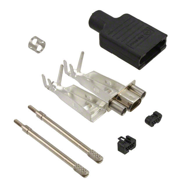
■ Cinch overmold kits enable you to overmold the connector of the cable assembly for less material and process cost (versus a metal backshell),improved appearance,and improved shielding of the connector to help meet RFI/EMIrequirements. ■ An Overmold Kit catalog number consists of: - D*A or HTD Crimp and Poke connector. - Inside shielding cover. - Outside shielding cover. ■ You will also need to order the following: - Crimp and Poke stamped contacts must be ordered separately on page 4-22 for D*A and page 4-18 for HTD connectors. - Ferrules are required,but must be ordered separately according to the size necessary to accommodate the wire. See page 4-25. - Termination tooling is required to crimp the wires on the connector. - A hand tool and appropriate crimping die are required for crimping the ferrule. ■ All specifications on the connector portion of the overmold kit can be found on pages 4-16 thru 4-17 for HPD 1.5 density and pages 4-20 thru 4-21 for D*A series. Shield Covers: Steel (stamped) with tin/lead finish Ferrule: Brass Dimensions Overmold Shielding Kits C D E F G H Positions in mm in mm in mm in mm Deg. in mm 9 Plug 0.270 6.86 0.705 17.91 1.320 33.53 0.520 13.21 75° 0.440 11.18 9 Socket 0.285 7.24 0.705 17.91 1.320 33.53 0.520 13.21 75° 0.440 11.18 15 Plug 0.270 6.86 1.050 26.67 1.320 33.53 0.520 13.21 58° 0.440 11.18 15 Socket 0.285 7.24 1.050 26.67 1.320 33.53 0.520 13.21 58° 0.440 11.18 25 Plug 0.275 6.99 1.590 40.39 1.320 33.53 0.520 13.21 40° 0.440 11.18 25 Socket 0.285 7.24 1.590 40.39 1.320 33.53 0.520 13.21 40° 0.440 11.18 37 Plug 0.275 6.99 2.240 56.90 1.620 41.15 0.750 19.05 32° 0.520 13.21 37 Socket 0.285 7.24 2.240 56.90 1.620 41.15 0.750 19.05 32° 0.520 13.21 Call Toll Free: 1 (800) 323-9612 4-24
Overmold Kits (Cont’d) Ordering Information D*A Series Crimp and Poke Overmold Kits Tin-plated shell Positions Plugs Sockets 9 DEAO-9PTI-FO1 DEAO-9ST-FO1 15 DAAO-15PTI-FO1 DAAO-15ST-FO1 25 DBAO-25PTI-FO1 DBAO-25ST-FO1 37 DCAO-37PTI-FO1 DCAO-37ST-FO1 HTD Series 1.5 Density Plugs Overmold Kits Size Shell Size Catalog Number 15 E HTDEO-15PTI-FO1 26 A HTDAO-26PTI-FO1 44 B HTDBO-44PTI-FO1 Crimp Ferrule Ordering Information Catalog J K L Crimp Die Number Type in mm in mm in mm Catalog No. CF-51 1 .437 11.10 .200 5.08 .450 11.43 CD-07 CF-42 1 .437 11.10 .235 5.97 .450 11.43 CD-00 CF-43 1 .437 11.10 .250 6.35 .450 11.43 CD-01 CF-44 1 .437 11.10 .325 8.26 .450 11.43 CD-02 CF-45 1 .437 11.10 .350 8.89 .450 11.43 CD-03 CF-46 1 .437 11.10 375 9.53 .450 11.43 CD-04 CF-47 2 .437 11.10 .437 11.10 .450 11.43 CD-05 CF-50 2 .460 11.68 .460 11.68 .450 11.43 CD-06 • Pneumatic Bench Top Press for Crimping Ferrules #FCT-551. See page 4-103. • Hand Tool for Crimping Ferrules #FCT-552. See page 4-103. 4-25 Call Toll Free: 1 (800) 323-9612
■ Offered in 9,15,25,37,and 50 position plugs and sockets (except right-angle PCBconnectors- 9 ,15,and 25 positions). ■ Available with gold flash or 30µin.gold plating. ■ Offered with .120 mounting holes,optional 4-40 clinch nuts,or dual float bushings (except right- angle PCBconnectors-mounting holes only). ■ Approvals: • UL Recognized - Files E170218 (UL1977) and E130965 (UL1863). • CSAApproved - File LR31996. ■ See pages 4-5 thru 4-10 for standard dimensions,contact arrangements,and panel mounting specifications. Insulator Material: Glass-filled nylon (black), UL94 V-O rated Connector Shell: Steel with zinc plating and yellow chromate finish or tin plating (grounding indents on plug) 4-40 Clinch Nut: Steel with cadmium plating and yellow chromate finish Dual Float Bushing: Stainless steel, passivated Operating Temperature: -65°C to + 125°C Shock: 50G peak per MIL-STD-202, Method 213, Condition G Vibration: 12 cycles in three perpendicular directions @ 10-2000Hz, per MIL-STD-202, Method 204, Condition D Moisture Resistance: 90-95% relative humidity @ 40°C for 96 hours per MIL-STD-202, Method 103 Withstanding Voltage: Minimum 1000V RMS @ sea level Current Rating: 5 Amps Contact Resistance: 2.7 milliohms maximum Insulation Resistance: 5000 megohms maximum (initial);1000 megohms (minimum) after environmental testing Individual Contact Insertion and Separation Force (minimum/maximum): 0.7 oz./12 oz. Durability: 500 mating cycles Call Toll Free: 1 (800) 323-9612 4-26
• Machined contacts supplied loose with connector or can be ordered separately. Use with 20-24 AWG wire. • Stamped Contacts (order separately) for use when ordering connector with contacts not included (-FO option). Use with 20-28 AWG wire. - Available in 10K reel. - Order reels of stamped contacts separately. Materials • Contact Material: Plug - Brass (stamped) or copper alloy (machined). Socket - Phosphor bronze (stamped) or copper alloy (machined). • Contact Plating: - Stamped Plugs and Sockets: Gold flash or 30µin.gold and gold flash on the remainder. All over nickel. - Machined Plugs and Sockets: Gold flash or 30µin.gold. All over nickel. Termination Tooling • Semi-Automatic Stripper Crimper for Stamped Contacts on 10K PC reels: #ESC-20-3. See page 4-102. • Contact Insertion/Extraction: #CIET-20-HDB.See page 4-101. • Loose Contact Crimp Tool: Machined Contact - #M22520/2-01. See page 4-103. For Positioner as required see page 4-103. Stamped Contacts #BT-20-HC see page 4-101. No positioner required. 4-27 Call Toll Free: 1 (800) 323-9612
Ordering Information D*U Crimp and Poke Plugs Zinc-Plated Shell with Yellow Chromate Finish Mounting Holes 4-40 Clinch Nuts Dual Float Bushings Contacts Without Contacts Without Contacts Without Position Included Contacts Included Contacts Included Contacts 9 DEU-9P DEU-9P-FO DEUE-9-P DEUE-9P-FO DEUY-9P DEUY-9P-FO 15 DAU-15P DAU-15P-FO DAUE-15-P DAUE-15-P-FO DAUY-15P DAUY-15P-FO 25 DBU-25P DBU-25P-FO DBUE-25-P DBUE-25P-FO DBUY-25P DBUY-25P-FO 37 DCU-37P DCU-37P-FO DCUE-37-P DCUE-37P-FO DCUY-37P DCUY-37P-FO 50 DDU-50P DDU-50P-FO DDUE-50-P DDUE-50P-FO DDUY-50P DDUY-50P-FO Tin-Plated Shell with Grounding Indents Mounting Holes 4-40 Clinch Nuts Dual Float Bushings Contacts Without Contacts Without Contacts Without Position Included Contacts Included Contacts Included Contacts 9 DEU-9PTI DEU-9PTI-FO DEUE-9PTI DEUE-9PTI-FO DEUY-9PTI DEUY-9PTI-FO 15 DAU-15PTI DAU-15PTI-FO DAUE-15PTI DAUE-15PTI-FO DAUY-15PTI DAUY-15PTI-FO 25 DBU-25PTI DBU-25PTI-FO DBUE-25PTI DBUE-25PTI-FO DBUY-25PTI DBUY-25PTI-FO 37 DCU-37PTI DCU-37PTI-FO DCUE-37PTI DCUE-37PTI-FO DCUY-37PTI DCUY-37PTI-FO 50 DDU-50PTI DDU-50PTI-FO DDUE-50PTI DDUE-50PTI-FO DDUY-50PTI DDUY-50PTI-FO D*U Crimp and Poke Sockets Zinc-Plated Shell with Yellow Chromate Finish Mounting Holes 4-40 Clinch Nuts Dual Float Bushings Contacts Without Contacts Without Contacts Without Position Included Contacts Included Contacts Included Contacts 9 DEU-9S DEU-9S-FO DEUE-9S DEUE-9S-FO DEUY-9S DEUY-9S-FO 15 DAU-15S DAU-15S-FO DAUE-15S DAUE-15S-FO DAUY-15S DAUY-15S-FO 25 DBU-25S DBU-25S-FO DBUE-25S DBUE-25S-FO DBUY-25S DBUY-25S-FO 37 DCU-37S DCU-37S-FO DCUE-37S DCUE-37S-FO DCUY-37S DCUY-37S-FO 50 DDU-50S DDU-50S-FO DDUE-50S DDUE-50S-FO DDUY-50S DDUY-50S-FO Tin-Plated Shell Mounting Holes 4-40 Clinch Nuts Dual Float Bushings Contacts Without Contacts Without Contacts Without Position Included Contacts Included Contacts Included Contacts 9 DEU-9ST DEU-9ST-FO DEUE-9ST DEUE-9ST-FO DEUY-9ST DEUY-9ST-FO 15 DAU-15ST DAU-15ST-FO DAUE-15ST DAUE-15ST-FO DAUY-15ST DAUY-15ST-FO 25 DBU-25ST DBU-25ST-FO DBUE-25ST DBUE-25ST-FO DBUY-25ST DBUY-25ST-FO 37 DCU-37ST DCU-37ST-FO DCUE-37ST DCUE-37ST-FO DCUY-37ST DCUY-37ST-FO 50 DDU-50ST DDU-50ST-FO DDUE-50ST DDUE-50ST-FO DDUY-50ST DDUY-50ST-FO Call Toll Free: 1 (800) 323-9612 4-28
Machined Contacts • 20-24 AWG Wire Plug Socket Dimensions A B C Max. Wire Description AWG in mm in mm in mm Pin #20, 22, 24 .066 1.67 .045 1.14 .537 13.64 Socket #20, 22, 24 .066 1.67 .045 1.14 .523 13.28 Ordering Information D*USeries Loose-Piece Machined Contacts Gold Flash 30µin.Gold Pin 030-1952-000 030-1952-030 Socket 030-1953-000 030-1953-030 Stamped Contacts • 20-28 AWG Wire Plug Socket Ordering Information D*USeries Stamped Contacts on 10K Reels Gold Flash 30µin.Gold Pin BCL-1964-20P D110238-034 Socket BCL-1963-20S D110238-035 4-29 Call Toll Free: 1 (800) 323-9612
• .445" footprint. • .024" contact diameter. Materials • Contact Material: Socket - Copper alloy (machined), Plug - Brass (machined). • Contact Plating: Gold flash or 30µin.gold. All over nickel. • Mounting bracket: Black nylon. Can be removed if necessary. yp. Ordering Information D*U Right-Angle Plugs Zinc-Plated Shell with Yellow Chromate Finish Tin-Plated Shell with Grounding Indents Positions Gold Flash 30µin.Gold Gold Flash 30µin.Gold 9 DEU-9PAD DEU-9PAD-30 DEU-9PADTI DEU-9PADTI-30 15 DAU-15PAD DAU-15PAD-30 DAU-15PADTI DAU-15PADTI-30 25 DBU-25PAD DBU-25PAD-30 DBU-25PADTI DBU-25PADTI-30 D*U Right-Angle Sockets Zinc-Plated Shell with Yellow Chromate Finish Tin-Plated Shell Positions Gold Flash 30µin.Gold Gold Flash 30µin.Gold 9 DEU-9SAD DEU-9SAD-30 DEU-9SADT DEU-9SADT-30 15 DAU-15SAD DAU-15SAD-30 DAU-15SADT DAU-15SADT-30 25 DBU-25SAD DBU-25SAD-30 DBU-25SADT DBU-25SADT-30 Call Toll Free: 1 (800) 323-9612 4-30
• .024" contact diameter. • Longer rear insulator provides integral standoff from PCB. Materials • Contact Material: Plug - Brass (machined), Socket - Copper alloy (machined). • Contact Plating: Gold flash or 30µin.gold. All over nickel. Ordering Information Vertical Plugs Zinc-Plated Shell with Yellow Chromate Finish Mounting Holes 4-40 Clinch Nuts Dual Float Bushings Positions Gold Flash 30µin.Gold Gold Flash 30µin.Gold Gold Flash 30µin.Gold 9 DEU-9PBF DEU-9PBF-30 DEUE-9PBF DEUE-9PBF-30 DEUY-9PBF DEUY-9PBF-30 15 DAU-15PBF DAU-15PBF-30 DAUE-15PBF DAUE-15PBF-30 DAUY-15PBF DAUY-15PBF-30 25 DBU-25PBF DBU-25PBF-30 DBUE-25PBF DBUE-25PBF-30 DBUY-25PBF DBUY-25PBF-30 37 DCU-37PBF DCU-37PBF-30 DCUE-37PBF DCUE-37PBF-30 DCUY-37PBF DCUY-37PBF-30 50 DDU-50PBF DDU-50PBF-30 DDUE-50PBF DDUE-50PBF-30 DDUY-50PBF DDUY-50PBF-30 Tin-Plated Shell with Grounding Indents Mounting Holes 4-40 Clinch Nuts Dual Float Bushings Positions Gold Flash 30µin.Gold Gold Flash 30µin.Gold Gold Flash 30µin.Gold 9 DEU-9PBFTI DEU-9PBFTI-30 DEUE-9PBFTI DEUE-9PBFTI-30 DEUY-9PBFTI DEUY-9PBFTI-30 15 DAU-15PBFTI DAU-15PBFTI-30 DAUE-15PBFTI DAUE-15PBFTI-30 DAUY-15PBFTI DAUY-15PBFTI-30 25 DBU-25PBFTI DBU-25PBFTI-30 DBUE-25PBFTI DBUE-25PBFTI-30 DBUY-25PBFTI DBUY-25PBFTI-30 37 DCU-37PBFTI DCU-37PBFTI-30 DCUE-37PBFTI DCUE-37PBFTI-30 DCUY-37PBFTI DCUY-37PBFTI-30 50 DDU-50PBFTI DDU-50PBFTI-30 DDUE-50PBFTI DDUE-50PBFTI-30 DDUY-50PBFTI DDUY-50PBFTI-30 4-31 Call Toll Free: 1 (800) 323-9612
Ordering Information (Cont’d) Vertical Sockets Zinc-Plated Shell with Yellow Chromate Finish Mounting Holes 4-40 Clinch Nuts Dual Float Bushings Positions Gold Flash 30µin.Gold Gold Flash 30µin.Gold Gold Flash 30µin.Gold 9 DEU-9SBF DEU-9SBF-30 DEUE-9SBF DEUE-9SBF-30 DEUY-9SBF DEUY-9SBF-30 15 DAU-15SBF DAU-15SBF-30 DAUE-15SBF DAUE-15SBF-30 DAUY-15SBF DAUY-15SBF-30 25 DBU-25SBF DBU-25SBF-30 DBUE-25SBF DBUE-25SBF-30 DBUY-25SBF DBUY-25SBF-30 37 DCU-37SBF DCU-37SBF-30 DCUE-37SBF DCUE-37SBF-30 DCUY-37SBF DCUY-37SBF-30 50 DDU-50SBF DDU-50SBF-30 DDUE-50SBF DDUE-50SBF-30 DDUY-50SBF DDUY-50SBF-30 Tin-Plated Shell Mounting Holes 4-40 Clinch Nuts Dual Float Bushings Positions Gold Flash 30µin.Gold Gold Flash 30µin.Gold Gold Flash 30µin.Gold 9 DEU-9SBFT DEU-9SBFT-30 DEUE-9SBFT DEUE-9SBFT-30 DEUY-9SBFT DEUY-9SBFT-30 15 DAU-15SBFT DAU-15SBFT-30 DAUE-15SBFT DAUE-15SBFT-30 DAUY-15SBFT DAUY-15SBFT-30 25 DBU-25SBFT DBU-25SBFT-30 DBUE-25SBFT DBUE-25SBFT-30 DBUY-25SBFT DBUY-25SBFT-30 37 DCU-37SBFT DCU-37SBFT-30 DCUE-37SBFT DCUE-37SBFT-30 DCUY-37SBFT DCUY-37SBFT-30 50 DDU-50SBFT DDU-50SBFT-30 DDUE-50SBFT DDUE-50SBFT-30 DDUY-50SBFT DDUY-50SBFT-30 Call Toll Free: 1 (800) 323-9612 4-32
■ Offered in 9,15,25,and 37 position plugs and sockets. ■ Available in Solder Cup and IDC (insulation displacement) terminations for discrete wire. ■ Offered with .120 mounting holes. ■ Approvals: • UL Recognized - Files E170218 (UL1977) and E130965 (UL1863). • CSAApproved - File LR31996. ■ See pages 4-5 thru 4-10 for standard dimensions,contact arrangements,and panel mounting specifications. Insulator Material: Glass-filled polyester (black), UL 94 V-O rated Connector Shell: Steel with zinc plating and yellow chromate finish or tin plating (grounding indents on plug) Contact Material: Phosphor bronze (stamped) Contact Plating: Gold flash or 30µin.gold in mating area and gold flash on the remainder. All over nickel. Operating Temperature: -65°C to + 125°C Shock: 50G peak per MIL-STD-202, Method 213, Condition G Vibration: 12 cycles in three perpendicular directions @ 10-2000Hz, per MIL-STD-202, Method 204, Condition D Moisture Resistance: 90-95% relative humidity @ 40°C for 96 hours per MIL-STD-202, Method 103 Withstanding Voltage: Minimum 1000V RMS @ sea level Current Rating: 3 Amps Contact Resistance: 2.7 milliohms maximum Insulation Resistance: 5000 megohms maximum (initial); 1000 megohms (minimum) after environmental testing Individual Contact Insertion and Separation Force (minimum/maximum): 0.7 oz./12 oz. Durability: 500 mating cycles Call Toll Free: 1 (800) 323-9612 4-34
• Solder channels between barriers permit single-pass soldering of each row without solder bridging. • Will accommodate up to 22 AWG wire. Ordering Information Solder Cup Plugs Zinc-Plated Shell Tin-Plated Shell with Yellow Chromate Finish with Grounding Indents Positions Gold Flash 30µin.Gold Gold Flash 30µin.Gold 9 TE-9PS TE-9PS-30 TE-9PTIS TE-9PTIS-30 15 TA-15PS TA-15PS-30 TA-15PTIS TA-15PTIS-30 25 TB-25PS TB-25PS-30 TB-25PTIS TB-25PTIS-30 37 TC-37PS TC-37PS-30 TC-37PTIS TC-37PTIS-30 Solder Cup Sockets Zinc-Plated Shell Tin-Plated Shell with Yellow Chromate Finish Positions Gold Flash 30µin.Gold Gold Flash 30µin.Gold 9 TE-9SS TE-9SS-30 TE-9STS TE-9STS-30 15 TA-15SS TA-15SS-30 TA-15STS TA-15STS-30 25 TB-25SS TB-25SS-30 TB-25STS TB-25STS-30 37 TC-37SS TC-37SS-30 TC-37STS TC-37STS-30 4-35 Call Toll Free: 1 (800) 323-9612
• Will accommodate 24-26 AWGsolid or stranded PVC wire. Ordering Information IDC Plugs Zinc-Plated Shell Tin-Plated Shell with Yellow Chromate Finish with Grounding Indents Positions Gold Flash 30µin.Gold Gold Flash 30µin.Gold 9 TE-9PSH TE-9PSH-30 TES-9PTI TES-9PTI-30 15 TA-15PSH TA-15PSH-30 TAS-15PTI TAS-15PTI-30 25 TB-25PSH TB-25PSH-30 TBS-25PTI TBS-25PTI-30 37 TC-37PSH TC-37PSH-30 TCS-37PTI TCS-37PTI-30 IDC Sockets Zinc-Plated Shell Tin-Plated Shell with Yellow Chromate Finish Positions Gold Flash 30µin.Gold Gold Flash 30µin.Gold 9 TE-9SSH TE-9SSH-30 TES-9ST TES-9ST-30 15 TA-15SSH TA-15SSH-30 TAS-15ST TAS-15ST-30 25 TB-25SSH TB-25SSH-30 TBS-25ST TBS-25ST-30 37 TC-37SSH TC-37SSH-30 TCS-37ST TCS-37ST-30 Call Toll Free: 1 (800) 323-9612 4-36
• Auto-Clinch D Semi-Automatic Termination Tool #ACD-432: See page 4-100. • Certi-Clinch D Manual Termination Tool #SD-CCWN: For 24-26 AWG wire: See page 4-100. • Uni-Clinch D Single-Wire Hand Insertion Tool #SD-UC: See page 4-100. • Super D Manual Stay Band Tool #SD-MSBT: See page 4-100. • Optional strain relief covers for connectors when backshell is not required. Ordering Information Positions Catalog No. 9 SSD-WC9 15 SSD-WC15 25 SSD-WC25 37 SSD-WC37 • One-piece cover for 9 contact size. Order one per connector. Two-piece cover for other sizes. Order two per connector. • Cover fits both plug and socket. 4-37 Call Toll Free: 1 (800) 323-9612
• For use only with SDH Series Gray Backshell on pages 4-89 thru 4-90. • Offered in 9, 15, 25, and 37 position plugs and sockets. • Connector will accommodate 24-28 AWG wire. • Offered with plain flanges and .120 mounting holes, threaded bushings, latch blocks, or latch blocks and threaded bushings. • Auto-Clinch D Semi-Automatic Termination Tool #ACD-432: See page 4-100. • Certi-Clinch D Manual Termination Tool #SD-CC for 24-28 AWG wire: See page 4-100. • Uni-Clinch D Single-Wire Hand Insertion Tool #SD-UC: See page 4-100. • Super D Manual Stay Band Tool #SD-MSBT: See page 4-100. Dimensions A A B CP CS D Positions in mm in mm in mm in mm in mm in mm 9 1.209 30.71 1.309 33.25 .984 24.99 .668 16.96 .642 16.31 .592 15.04 15 1.536 39.01 1.636 41.55 1.312 33.32 .995 25.28 .970 24.64 .918 23.31 25 2.079 52.81 2.179 55.35 1.852 47.04 1.535 38.99 1.512 38.40 1.462 37.13 37 2.724 69.19 2.824 71.73 2.500 63.50 2.183 55.45 2.158 54.81 2.114 53.70 Call Toll Free: 1 (800) 323-9612 4-38
Ordering Information IDC All-Plastic Plugs Plain Flange Mounting Holes 4-40 Threaded Bushings Positions Gold Flash 30µin.Gold Gold Flash 30µin.Gold 9 TE-9P TE-9P-30 TE-9PTB TE-9PTB-30 15 TA-15P TA-15P-30 TA-15PTB TA-15PTB-30 25 TB-25P TB-25P-30 TB-25PTB TB-25PTB-30 37 TC-37P TC-37P-30 TC-37PTB TC-37PTB-30 Flange with Latch Block Mounting Holes 4-40 Threaded Bushings Positions Gold Flash 30µin.Gold Gold Flash 30µin.Gold 9 TE-9PLB TE-9PLB-30 TE-9PLB-1 TE-9PLB-1-30 15 TA-15PLB TA-15PLB-30 TA-15PLB-1 TA-15PLB-1-30 25 TB-25PLB TB-25PLB-30 TB-25PLB-1 TB-25PLB-1-30 37 TC-37PLB TC-37PLB-30 TC-37PLB-1 TC-37PLB-1-30 IDC All-Plastic Sockets Plain Flange Mounting Holes 4-40 Threaded Bushings Positions Gold Flash 30µin.Gold Gold Flash 30µin.Gold 9 TE-9S TE-9S-30 TE-9STB TE-9STB-30 15 TA-15S TA-15S-30 TA-15STB TA-15STB-30 25 TB-25S TB-25S-30 TB-25STB TB-25STB-30 37 TC-37S TC-37S-30 TC-37STB TC-37STB-30 Flange with Latch Block Mounting Holes 4-40 Threaded Bushings Positions Gold Flash 30µin.Gold Gold Flash 30µin.Gold 9 TE-9SLB TE-9SLB-30 TE-9SLB-1 TE-9SLB-1-30 15 TA-15SLB TA-15SLB-30 TA-15SLB-1 TA-15SLB-1-30 25 TB-25SLB TB-25SLB-30 TB-25SLB-1 TB-25SLB-1-30 37 TC-37SLB TC-37SLB-30 TC-37SLB-1 TC-37SLB-1-30 4-39 Call Toll Free: 1 (800) 323-9612
■ Offered in Wire Wrap and Solder Cup styles for wire termination and vertical style for PCB mount. ■ Offered with .120 mounting holes,4-40 clinch nuts,and dual float bushings. ■ Offered in 9,15,25,37,and 50 position plugs and sockets. ■ Available with gold flash or 30µin.gold plating. ■ Approvals: • ULRecognized - Files E170218 (UL1977) and E130965 (UL1863). • CSAApproved - File LR31996. ■ See pages 4-5 thru 4-10 for standard dimensions,contact arrangements,and panel mounting specifications. Insulator Material: Glass-filled polyester (white), UL 94V-O rated Connector Shell: Steel with zinc plating and yellow chromate finish or tin plating (grounding indents on plug) 4-40 Clinch Nut: Steel with cadmium plating and yellow chromate finish Dual Float Bushing: Stainless steel, passivated Operating Temperature: -65°C to + 125°C Shock: 50G peak per MIL-STD-202, Method 213, Condition G Vibration: 12 cycles in three perpendicular directions @ 10-2000Hz, per MIL-STD-202, Method 204, Condition D Moisture Resistance: 90-95% relative humidity @ 40°C for 96 hours per MIL-STD-202, Method 103 Withstanding Voltage: Minimum 1250V RMS @ sea level Current Rating: 5 Amps Contact Resistance: 2.7 milliohms maximum Insulation Resistance: 5000 megohms maximum (initial); 1000 megohms (minimum) after environmental testing Individual Contact Insertion and Separation Force (minimum/maximum): 0.7 oz./12 oz. Durability: 500 mating cycles Call Toll Free: 1 (800) 323-9612 4-40
• Available with stamped or machined contacts. • Will accommodate up to 20 AWG wire. Materials • Contact Material: Copper Alloy • Contact Plating: - Stamped contacts with gold flash or 30µin.gold in mating area, gold flash or tin/lead on remainder. All over nickel. - Screw machine contacts with gold flash or 30µin.gold. All over nickel. Ordering Information Solder Cup Plugs Zinc-Plated Shell with Yellow Chromate Finish Stamped Contact with Gold Flash in Solder Cup Mounting Holes 4-40 Clinch Nuts Dual Float Bushings Positions Gold Flash 30µin.Gold Gold Flash 30µin.Gold Gold Flash 30µin.Gold 9 DE-9P DE-9P-30 DEE-9P DEE-9P-30 DEY-9P DEY-9P-30 15 DA-15P DA-15P-30 DAE-15P DAE-15P-30 DAY15P DAY-15P-30 25 DB-25P DB-25P-30 DBE-25P DBE-25P-30 DBY-25P DBY-25P-30 37 DC-37P DC-37P-30 DCE-37P DCE-37P-30 DCY-37P DCY-37P-30 50 DD-50P DD-50P-30 DDE-50P DDE-50P-30 DDY-50P DDY-50P-30 Stamped Contact with Tin/Lead in Solder Cup Mounting Holes 4-40 Clinch Nuts Dual Float Bushings Positions Gold Flash 30µin.Gold Gold Flash 30µin.Gold Gold Flash 30µin.Gold 9 DE-9P-II DE-9P-II-30 DEE-9P-II DEE-9P-II-30 DEY-9P-II DEY-9P-II-30 15 DA-15P-II DA-15P-II-30 DAE-15P-II DAE-15P-II-30 DAY-15P-II DAY-15-PII-30 25 DB-25P-II DB-25P-II-30 DBE-25P-II DBE-25P-II-30 DBY-25P-II DBY-25-PII-30 37 DC-37P-II DC-37P-II-30 DCE-37P-II DCE-37P-II-30 DCY-37-P-II DCY-37-PII-30 50 DD-50P-II DD-50P-II-30 DDE-50P-II DDE-50P-II-30 DDY-50-P-II DDY-50-PII-30 Screw Machine Contact Mounting Holes 4-40 Clinch Nuts Dual Float Bushings Positions Gold Flash 30µin.Gold Gold Flash 30µin.Gold Gold Flash 30µin.Gold 9 DE-9P-SM DE-9P-SM-30 DEE-9P-SM DEE-9P-SM-30 DEY-9P-SM DEY-9P-SM-30 15 DA-15P-SM DA-15P-SM-30 DAE-15P-SM DAE-15P-SM-30 DAY-15P-SM DAY-15P-SM-30 25 DB-25P-SM DB-25P-SM-30 DBE-25P-SM DBE-25P-SM-30 DBY-25P-SM DBY-25P-SM-30 37 DC-37P-SM DC-37P-SM-30 DCE-37P-SM DCE-37P-SM-30 DCY-37P-SM DCY-37P-SM-30 50 DD-50P-SM DD-50P-SM-30 DDE-50P-SM DDE-50P-SM-30 DDY-50P-SM DDY-50P-SM-30 4-41 Call Toll Free: 1 (800) 323-9612
Ordering Information Solder Cup Plugs (Cont’d) Tin-Plated Shell with Grounding Indents Stamped Contact with Gold Flash in Solder Cup Mounting Holes 4-40 Clinch Nuts Dual Float Bushings Positions Gold Flash 30µin.Gold Gold Flash 30µin.Gold Gold Flash 30µin.Gold 9 DE-9PTI DE-9PTI-30 DEE-9PTI DEE-9PTI-30 DEY-9PTI DEY-9PTI-30 15 DA-15PTI DA-15PTI-30 DAE-15PTI DAE-15PTI-30 DAY-15PTI DAY-15PTI-30 25 DB-25PTI DB-25PTI-30 DBE-25PTI DBE-25PTI-30 DBY-25PTI DBY-25PTI-30 37 DC-37PTI DC-37PTI-30 DCE-37PTI DCE-37PTI-30 DCY-37PTI DCY-37PTI-30 50 DD-50PTI DD-50PTI-30 DDE-50PTI DDE-50PTI-30 DDY-50PTI DDY-50PTI-30 Stamped Contact with Tin/Lead in Solder Cup Mounting Holes 4-40 Clinch Nuts Dual Float Bushings Positions Gold Flash 30µin.Gold Gold Flash 30µin.Gold Gold Flash 30µin.Gold 9 DE-9PTI-II DE-9PTI-II-30 DEE-9PTI-II DEE-9PTI-II-30 DEY-9PTI-II DEY-9PTI-II-30 15 DA-15PTI-II DA-15PTI-II-30 DAE-15PTI-II DAE-15PTI-II-30 DAY-15PTI-II DAY-15PTI-II-30 25 DB-25PTI-II DB-25PTI-II-30 DBE-25PTI-II DBE-25PTI-II-30 DBY-25PTI-II DBY-25PTI-II-30 37 DC-37PTI-II DC-37PTI-II-30 DCE-37PTI-II DCE-37PTI-II-30 DCY-37PTI-II DCY-37PTI-II-30 50 DD-50PTI-II DD-50PTI-II-30 DDE-50PTI-II DDE-50PTI-II-30 DDY-50PTI-II DDY-50PTI-II-30 Screw Machine Contact Mounting Holes 4-40 Clinch Nuts Dual Float Bushings Positions Gold Flash 30µin.Gold Gold Flash 30µin.Gold Gold Flash 30µin.Gold 9 DE-9PTI-SM DE-9PTI-SM-30 DEE-9PTI-SM DEE-9PTI-SM-30 DEY-9PTI-SM DEY-9PTI-SM-30 15 DA-15PTI-SM DA-15PTI-SM-30 DAE-15PTI-SM DAE-15PTI-SM-30 DAY-15PTI-SM DAY-15PTI-SM-30 25 DB-25PTI-SM DB-25PTI-SM-30 DBE-25PTI-SM DBE-25PTI-SM-30 DBY-25PTI-SM DBY-25PTI-SM-30 37 DC-37PTI-SM DC-37PTI-SM-30 DCE-37PTI-SM DCE-37PTI-SM-30 DCY-37PTI-SM DCY-37PTI-SM-30 50 DD-50PTI-SM DD-50PTI-SM-30 DDE-50PTI-SM DDE-50PTI-SM-30 DDY-50PTI-SM DDY-50PTI-SM-30 Call Toll Free: 1 (800) 323-9612 4-42
Ordering Information Solder Cup Sockets Zinc-Plated Shell with Yellow Chromate Finish Stamped Contact with Gold Flash in Solder Cup Mounting Holes 4-40 Clinch Nuts Dual Float Bushings Positions Gold Flash 30µin.Gold Gold Flash 30µin.Gold Gold Flash 30µin.Gold 9 DE-9S DE-9S-30 DEE-9S DEE-9S-30 DEY-9S DEY-9S-30 15 DA-15S DA-15S-30 DAE-15S DAE-15S-30 DAY-15S DAY-15S-30 25 DB-25S DB-25S-30 DBE-25S DBE-25S-30 DBY-25S DBY-25S-30 37 DC-37S DC-37S-30 DCE-37S DCE-37S-30 DCY-37S DCY-37S-30 50 DD-50S DD-50S-30 DDE-50S DDE-50S-30 DDY-50S DDY-50S-30 Stamped Contact Tin/Lead in Solder Cup Mounting Holes 4-40 Clinch Nuts Dual Float Bushings Positions Gold Flash 30µin.Gold Gold Flash 30µin.Gold Gold Flash 30µin.Gold 9 DE-9S-II DE-9S-II-30 DEE-9S-II DEE-9S-II-30 DEY-9S-II DEY-9S-II-30 15 DA-15S-II DA-15S-II-30 DAE-15S-II DAE-15S-II-30 DAY-15S-II DAY-15S-II-30 25 DB-25S-II DB-25S-II-30 DBE-25S-II DBE-25S-II-30 DBY-25S-II DBY-25S-II-30 37 DC-37S-II DC-37S-II-30 DCE-37S-II DCE-37S-II-30 DCY-37S-II DCY-37S-II-30 50 DD-50S-II DD-50S-II-30 DDE-50S-II DDE-50S-II-30 DDY-50S-II DDY-50S-II-30 Screw Machine Contact Mounting Holes 4-40 Clinch Nuts Dual Float Bushings Positions Gold Flash 30µin.Gold Gold Flash 30µin.Gold Gold Flash 30µin.Gold 9 DE-9S-SM DE-9S-SM-30 DEE-9S-SM DEE-9S-SM-30 DEY-9S-SM DEY-9S-SM-30 15 DA-15S-SM DA-15S-SM-30 DAE-15S-SM DAE-15S-SM-30 DAY-15S-SM DAY-15S-SM-30 25 DB-25S-SM DB-25S-SM-30 DBE-25S-SM DBE-25S-SM-30 DBY-25S-SM DBY-25S-SM-30 37 DC-37S-SM DC-37S-SM-30 DCE-37S-SM DCE-37S-SM-30 DCY-37S-SM DCY-37S-SM-30 50 DD-50S-SM DD-50S-SM-30 DDE-50S-SM DDE-50S-SM-30 DDY-50S-SM DDY-50S-SM-30 Tin-Plated Shell Stamped Contact with Gold Flash in Solder Cup Mounting Holes 4-40 Clinch Nuts Dual Float Bushings Positions Gold Flash 30µin.Gold Gold Flash 30µin.Gold Gold Flash 30µin.Gold 9 DE-9ST DE-9ST-30 DEE-9ST DEE-9ST-30 DEY-9ST DEY-9ST-30 15 DA-15ST DA-15ST-30 DAE-15ST DAE-15ST-30 DAY-15ST DAY-15ST-30 25 DB-25ST DB-25ST-30 DBE-25ST DBE-25ST-30 DBY-25ST DBY-25ST-30 37 DC-37ST DC-37ST-30 DCE-37ST DCE-37ST-30 DCY-37ST DCY-37ST-30 50 DD-50ST DD-50ST-30 DDE-50ST DDE-50ST-30 DDY-50ST DDY-50ST-30 Stamped Contact with Tin/Lead in Solder Cup Mounting Holes 4-40 Clinch Nuts Dual Float Bushings Positions Gold Flash 30µin.Gold Gold Flash 30µin.Gold Gold Flash 30µin.Gold 9 DE-9ST-II DE-9ST-II-30 DEE-9ST-II DEE-9ST-II-30 DEY-9ST-II DEY-9ST-II-30 15 DA-15ST-II DA-15ST-II-30 DAE-15ST-II DAE-15ST-II-30 DAY-15ST-II DAY-15ST-II-30 25 DB-25ST-II DB-25ST-II-30 DBE-25ST-II DBE-25ST-II-30 DBY-25ST-II DBY-25ST-II-30 37 DC-37ST-II DC-37ST-II-30 DCE-37ST-II DCE-37ST-II-30 DCY-37ST-II DCY-37ST-II-30 50 DD-50ST-II DD-50ST-II-30 DDE-50ST-II DDE-50ST-II-30 DDY-50ST-II DDY-50ST-II-30 Screw Machine Contact Mounting Holes 4-40 Clinch Nuts Dual Float Bushings Positions Gold Flash 30µin.Gold Gold Flash 30µin.Gold Gold Flash 30µin.Gold 9 DE-9ST-SM DE-9ST-SM-30 DEE-9ST-SM DEE-9ST-SM-30 DEY-9ST-SM DEY-9ST-SM-30 15 DA-15ST-SM DA-15ST-SM-30 DAE-15ST-SM DAE-15ST-SM-30 DAY-15ST-SM DAY-15ST-SM-30 25 DB-25ST-SM DB-25ST-SM-30 DBE-25ST-SM DBE-25ST-SM-30 DBY-25ST-SM DBY-25ST-SM-30 37 DC-37ST-SM DC-37ST-SM-30 DCE-37ST-SM DCE-37ST-SM-30 DCY-37ST-SM DCY-37ST-SM-30 50 DD-50ST-SM DD-50ST-SM-30 DDE-50ST-SM DDE-50ST-SM-30 DDY-50ST-SM DDY-50ST-SM-30 4-43 Call Toll Free: 1 (800) 323-9612
• .040" contact diameter. • Short rear insulator provides low profile on PCB. • Offered with .120 mounting holes, dual float bushings, or optional 4-40 clinch nuts. Materials • Contact Material: Socket - Phosphor bronze (machined), Plug - Brass (machined). • Contact Plating: Gold flash or 30µin.gold over nickel. 07) 97) Ordering Information Vertical PCB Plugs Zinc-Plated Shell with Yellow Chromate Finish Mounting Holes 4-40 Clinch Nuts Dual Float Bushings Positions Gold Flash 30µin.Gold Gold Flash 30µin.Gold Gold Flash 30µin.Gold 9 DE-9PV DE-9PV-30 DEE-9PV DEE-9PV-30 DEY-9PV DEY-9PV-30 15 DA-15PV DA-15PV-30 DAE-15PV DAE-15PV-30 DAY-15PV DAY-15PV-30 25 DB-25PV DB-25PV-30 DBE-25PV DBE-25PV-30 DBY-25PV DBY-25PV-30 37 DC-37PV DC-37PV-30 DCE-37PV DCE-37PV-30 DCY-37PV DCY-37PV-30 50 DD-50PV DD-50PV-30 DDE-50PV DDE-50PV-30 DCY-50PV DDY-50PV-30 Tin-Plated Shell with Grounding Indents Mounting Holes 4-40 Clinch Nuts Dual Float Bushings Positions Gold Flash 30µin.Gold Gold Flash 30µin.Gold Gold Flash 30µin.Gold 9 DE-9PVTI DE-9PVTI-30 DEE-9PVTI DEE-9PVTI-30 DEY-9PVTI DEY-9PVTI-30 15 DA-15PVTI DA-15PVTI-30 DAE-15PVTI DAE-15PVTI-30 DAY-15PVTI DAY-15PVTI-30 25 DB-25PVTI DB-25PVTI-30 DBE-25PVTI DBE-25PVTI-30 DBY-25PVTI DBY-25PVTI-30 37 DC-37PVTI DC-37PVTI-30 DCE-37PVTI DCE-37PVTI-30 DCY-37PVTI DCY-37PVTI-30 50 DD-50PVTI DD-50PVTI-30 DDE-50PVTI DDE-50PVTI-30 DCY-50PVTI DDY-50PVTI-30 Vertical PCB Sockets Zinc-Plated Shell with Yellow Chromate Finish Mounting Holes 4-40 Clinch Nuts Dual Float Bushings Positions Gold Flash 30µin.Gold Gold Flash 30µin.Gold Gold Flash 30µin.Gold 9 DE-9SV DE-9SV-30 DEE-9SV DEE-9SV-30 DEY-9SV DEY-9SV-30 15 DA-15SV DA-15SV-30 DAE-15SV DAE-15SV-30 DAY-15SV DAY-15SV-30 25 DB-25SV DB-25SV-30 DBE-25SV DBE-25SV-30 DBY-25SV DBY-25SV-30 37 DC-37SV DC-37SV-30 DCE-37SV DCE-37SV-30 DCY-37SV DCY-37SV-30 50 DD-50SV DD-50SV-30 DDE-50SV DDE-50SV-30 DCY-50SV DDY-50SV-30 Tin-Plated Shell Mounting Holes 4-40 Clinch Nuts Dual Float Bushings Positions Gold Flash 30µin.Gold Gold Flash 30µin.Gold Gold Flash 30µin.Gold 9 DE-9SVT DE-9SVT-30 DEE-9SVT DEE-9SVT-30 DEY-9SVT DEY-9SVT-30 15 DA-15SVT DA-15SVT-30 DAE-15SVT DAE-15SVT-30 DAY-15SVT DAY-15SVT-30 25 DB-25SVT DB-25SVT-30 DBE-25SVT DBE-25SVT-30 DBY-25SVT DBY-25SVT-30 37 DC-37SVT DC-37SVT-30 DCE-37SVT DCE-37SVT-30 DCY-37SVT DCY-37SVT-30 50 DD-50SVT DD-50SVT-30 DDE-50SVT DDE-50SVT-30 DDY-50SVT DDY-50SVT-30 Call Toll Free: 1 (800) 323-9612 4-44
• Reliable wire wrap termination. • Two contact lengths: .375" or .585". • .025" square contact tails. Materials • Contact Material: Copper alloy (machined). • Contact Plating: Gold flash or 30µin.gold. All over nickel. (9.53) o r (14.86) EF. Ordering Information Wire Wrap Plugs .375"Tail Length Zinc-Plated Shell with Yellow Chromate Finish Mounting Holes 4-40 Clinch Nuts Dual Float Bushings Positions Gold Flash 30µin.Gold Gold Flash 30µin.Gold Gold Flash 30µin.Gold 9 DE-9P-F179 DE-9P-F179-30 DEE-9P-F179 DEE-9P-F179-30 DEY-9P-F179 DEY-9P-F179-30 15 DA-15P-F179 DA-15P-F179-30 DAE-15P-F179 DAE-15P-F179-30 DAY-15P-F179 DAY-15P-F179-30 25 DB-25P-F179 DB-25P-F179-30 DBE-25P-F179 DBE-25P-F179-30 DBY-25P-F179 DBY-25P-F179-30 37 DC-37P-F179 DC-37P-F179-30 DCE-37P-F179 DCE-37P-F179-30 DCY-37P-F179 DCY-37P-F179-30 50 DD-50P-F179 DD-50P-F179-30 DDE-50P-F179 DDE-50P-F179-30 DDY-50P-F179 DDY-50P-F179-30 Tin-Plated Shell with Grounding Indents Mounting Holes 4-40 Clinch Nuts Dual Float Bushings Positions Gold Flash 30µin.Gold Gold Flash 30µin.Gold Gold Flash 30µin.Gold 9 DE-9PTI-F179 DE-9PTI-F179-30 DEE-9PTI-F179 DEE-9PTI-F179-30 DEY-9PTI-F179 DEY-9PTI-F179-30 15 DA-15PTI-F179 DA-15PTI-F179-30 DAE-15PTI-F179 DAE-15PTI-F179-30 DAY-15PTI-F179 DAY-15PTI-F179-30 25 DB-25PTI-F179 DB-25PTI-F179-30 DBE-25PTI-F179 DBE-25PTI-F179-30 DBY-25PTI-F179 DBY-25PTI-F179-30 37 DC-37PTI-F179 DC-37PTI-F179-30 DCE-37PTI-F179 DCE-37PTI-F179-30 DCY-37PTI-F179 DCY-37PTI-F179-30 50 DD-50PTI-F179 DD-50PTI-F179-30 DDE-50PTI-F179 DDE-50PTI-F179-30 DDY-50PTI-F179 DDY-50PTI-F179-30 4-45 Call Toll Free: 1 (800) 323-9612
Ordering Information Wire Wrap Plugs (Cont’d) .585"Tail Length Zinc-Plated Shell with Yellow Chromate Finish Mounting Holes 4-40 Clinch Nuts Dual Float Bushings Positions Gold Flash 30µin.Gold Gold Flash 30µin.Gold Gold Flash 30µin.Gold 9 DE-9P-F179C DE-9P-F179C-30 DEE-9P-F179C DEE-9PF-179C-30 DEY-9P-F179C DEY-9P-F179C-30 15 DA-15P-F179C DA-15P-F179C-30 DAE-15P-F179C DAE-15PF-179C-30 DAY-15P-F179C DAY-15P-F179C-30 25 DB-25P-F179C DB-25P-F179C-30 DBE-25P-F179C DBE-25PF-179C-30 DBY-25P-F179C DBY-25P-F179C-30 37 DC-37P-F179C DC-37P-F179C-30 DCE-37P-F179C DCE-37PF-179C-30 DCY-37P-F179C DCY-37P-F179C-30 50 DD-50P-F179C DD-50P-F179C-30 DDE-50P-F179C DDE-50PF-179C-30 DDY-50P-F179C DDY-50P-F179C-30 Tin-Plated Shell with Grounding Indents Mounting Holes 4-40 Clinch Nuts Dual Float Bushings Positions Gold Flash 30µin.Gold Gold Flash 30µin.Gold Gold Flash 30µin.Gold 9 DE-9PTI-F179C DE-9PTI-F179C-30 DEE-9PTI-F179C DEE-9PTI-F179C-30 DEY-9PTI-F179C DEY-9PTI-F179C-30 15 DA-15PTI-F179C DA-15PTI-F179C-30 DAE-15PTI-F179C DAE-15PTI-F179C-30 DAY-15PTI-F179C DAY-15PTI-F179C-30 25 DB-25PTI-F179C DB-25PTI-F179C-30 DBE-25PTI-F179C DBE-25PTI-F179C-30 DBY-25PTI-F179C DBY-25PTI-F179C-30 37 DC-37PTI-F179C DC-37PTI-F179C-30 DCE-37PTI-F179C DCE-37PTI-F179C-30 DCY-37PTI-F179C DCY-37PTI-F179C-30 50 DD-50PTI-F179C DD-50PTI-F179C-30 DDE-50PTI-F179C DDE-50PTI-F179C-30 DDY-50PTI-F179C DDY-50PTI-F179C-30 Call Toll Free: 1 (800) 323-9612 4-46
Ordering Information Wire Wrap Sockets .375"Tail Length Zinc-Plated Shell with Yellow Chromate Finish Mounting Holes 4-40 Clinch Nuts Dual Float Bushings Positions Gold Flash 30µin.Gold Gold Flash 30µin.Gold Gold Flash 30µin.Gold 9 DE-9S-F179 DE-9S-F179-30 DEE-9S-F179 DEE-9S-F179-30 DEY-9S-F179 DEY-9S-F179-30 15 DA-15S-F179 DA-15S-F179-30 DAE-15S-F179 DAE-15S-F179-30 DAY-15S-F179 DAY-15S-F179-30 25 DB-25S-F179 DB-25S-F179-30 DBE-25S-F179 DBE-25S-F179-30 DBY-25S-F179 DBY-25S-F179-30 37 DC-37S-F179 DC-37S-F179-30 DCE-37S-F179 DCE-37S-F179-30 DCY-37S-F179 DCY-37S-F179-30 50 DD-50S-F179 DD-50S-F179-30 DDE-50S-F179 DDE-50S-F179-30 DDY-50S-F179 DDY-50S-F179-30 Tin-Plated Shell Mounting Holes 4-40 Clinch Nuts Dual Float Bushings Positions Gold Flash 30µin.Gold Gold Flash 30µin.Gold Gold Flash 30µin.Gold 9 DE-9ST-F179 DE-9ST-F179-30 DEE-9ST-F179 DEE-9ST-F179-30 DEY-9ST-F179 DEY-9ST-F179-30 15 DA-15ST-F179 DA-15ST-F179-30 DAE-15ST-F179 DAE-15ST-F179-30 DAY-15ST-F179 DAY-15ST-F179-30 25 DB-25ST-F179 DB-25ST-F179-30 DBE-25ST-F179 DBE-25ST-F179-30 DBY-25ST-F179 DBY-25ST-F179-30 37 DC-37ST-F179 DC-37ST-F179-30 DCE-37ST-F179 DCE-37ST-F179-30 DCY-37ST-F179 DCY-37ST-F179-30 50 DD-50ST-F179 DD-50ST-F179-30 DDE-50ST-F179 DDE-50ST-F179-30 DDY-50ST-F179 DDY-50ST-F179-30 .585"Tail Length Zinc-Plated Shell with Yellow Chromate Finish Mounting Holes 4-40 Clinch Nuts Dual Float Bushings Positions Gold Flash 30µin.Gold Gold Flash 30µin.Gold Gold Flash 30µin.Gold 9 DE-9S-F179C DE-9S-F179C-30 DEE-9S-F179C DEE-9S-F179C-30 DEY-9S-F179C DEY-9S-F179C-30 15 DA-15S-F179C DA-15S-F179C-30 DAE-15S-F179C DAE-15S-F179C-30 DAY-15S-F179C DAY-15S-F179C-30 25 DB-25S-F179C DB-25S-F179C-30 DBE-25S-F179C DBE-25S-F179C-30 DBY-25S-F179C DBY-25S-F179C-30 37 DC-37S-F179C DC-37S-F179C-30 DCE-37S-F179C DCE-37S-F179C-30 DCY-37S-F179C DCY-37S-F179C-30 50 DD-50S-F179C DD-50S-F179C-30 DDE-50S-F179C DDE-50S-F179C-30 DDY-50S-F179C DDY-50S-F179C-30 Tin-Plated Shell Mounting Holes 4-40 Clinch Nuts Dual Float Bushings Positions Gold Flash 30µin.Gold Gold Flash 30µin.Gold Gold Flash 30µin.Gold 9 DE-9ST-F179C DE-9ST-F179C-30 DEE-9ST-F179C DEE-9ST-F179C-30 DEY-9ST-F179C DEY-9ST-F179C-30 15 DA-15ST-F179C DA-15ST-F179C-30 DAE-15ST-F179C DAE-15ST-F179C-30 DAY-15ST-F179C DAY-15ST-F179C-30 25 DB-25ST-F179C DB-25ST-F179C-30 DBE-25ST-F179C DBE-25ST-F179C-30 DBY-25ST-F179C DBY-25ST-F179C-30 37 DC-37ST-F179C DC-37ST-F179C-30 DCE-37ST-F179C DCE-37ST-F179C-30 DCY-37ST-F179C DCY-37ST-F179C-30 50 DD-50ST-F179C DD-50ST-F179C-30 DDE-50ST-F179C DDE-50ST-F179C-30 DDY-50ST-F179C DDY-50ST-F179C-30 4-47 Call Toll Free: 1 (800) 323-9612
■ Available in vertical and right-angle dip solder PCB connectors and solder cup version for wire termination. ■ Commercial version of M24308 military connectors with tin-plated or zinc-plated shell and 30µin.gold plating. ■ Monoblock green diallyl phthalate insulator for improved electrical performance. ■ Machined contacts for precision performance. ■ Offered in 9,15,25,37,and 50 (except right-angle version) position plugs and sockets. ■ Offered with .120 mounting holes,4-40 clinch nuts (except right-angle version),or dual float bushings (except right-angle version). ■ Approvals: • UL Recognized - Files E170218 (UL1977)and E130965 (UL1863). • CSAApproved - File LR31996. ■ See pages 4-5 thru 4-10 for standard dimensions,contact arrangements,and panel mounting specifications. Insulator Material: Glass-filled diallyl phthalate (green) UL 94V-0 rated Connector Shell: Steel with zinc plating and yellow chromate finish or tin plating (grounding indents on plug) Contact Material: Plug - Brass (machined), Socket - Phosphor bronze (machined) Contact Plating: 30µin.gold over nickel 4-40 Clinch Nut: Steel with cadmium plating and yellow chromate finish Dual Float Bushing: Stainless steel, passivated Operating Temperature: -65°C to + 125°C Shock: 50G peak per MIL-STD-202, Method 213, Condition G Vibration: 12 cycles in three perpendicular directions @ 10-2000Hz, per MIL-STD-202, Method 204, Condition D Moisture Resistance: 90-95% relative humidity @ 40°C for 96 hours per MIL-STD-202, Method 103 Withstanding Voltage: Minimum 1250V RMS @ sea level Current Rating: 5 Amps Contact Resistance: 2.7 milliohms maximum Insulation Resistance: 5000 megohms maximum (initial); 1000 megohms (minimum) after environmental testing Individual Contact Insertion and Separation Force (minimum/maximum): 0.7 oz./12 oz. Durability: 500 mating cycles Call Toll Free: 1 (800) 323-9612 4-48
• Will accommodate up to 20 AWGwire. Ordering Information Solder Cup Plugs Zinc-Plated Shell with Yellow Chromate Finish Tin-Plated Shell with Grounding Indents Positions Mounting Hole 4-40 Clinch Nut Dual Float Bushings Mounting Hole 4-40 Clinch Nut Dual Float Bushings 9 DEM-9P DEME-9P DEMY-9P DEM-9PTI DEME-9PTI DEMY-9PTI 15 DAM-15P DAME-15P DAMY-15P DAM-15PTI DAME-15PTI DAMY-15PTI 25 DBM-25P DBME-25P DBMY-25P DBM-25PTI DBME-25PTI DBMY-25PTI 37 DCM-37P DCME-37P DCMY-37P DCM-37PTI DCME-37PTI DCMY-37PTI 50 DDM-50P DDME-50P DDMY-50P DDM-50PTI DDME-50PTI DDMY-50PTI Solder Cup Sockets Zinc-Plated Shell with Yellow Chromate Finish Tin-Plated Shell Positions Mounting Hole 4-40 Clinch Nut Dual Float Bushings Mounting Hole 4-40 Clinch Nut Dual Float Bushings 9 DEM-9S DEME-9S DEMY-9S DEM-9ST DEME-9ST DEMY-9ST 15 DAM-15S DAME-15S DAMY-15S DAM-15ST DAME-15ST DAMY-15ST 25 DBM-25S DBME-25S DBMY-25S DBM-25ST DBME-25ST DBMY-25ST 37 DCM-37S DCME-37S DCMY-37S DCM-37ST DCME-37ST DCMY-37ST 50 DDM-50S DDME-50S DDMY-50S DDM-50ST DDME-50ST DDMY-50ST 4-49 Call Toll Free: 1 (800) 323-9612
• .283" footprint uses minimal board space. • Available with three contact tail lengths (.125", .158", and .185") and two contact diameters (.030" and .040"). Materials • Mounting bracket: Black nylon. Can be removed if necessary. Ordering Information Right-Angle PCBPlugs Zinc-Plated Shell with Yellow Chromate Finish .125 Tail Length .158 Tail Length .185 Tail Length .125 Tail Length .158 Tail Length .185 Tail Length Positions .030 Contact .030 Contact .030 Contact .040 Contact .040 Contact .040 Contact Diameter Diameter Diameter Diameter Diameter Diameter 9 DEM-9PD DEM-9PL DEM-9PS DEM-9PA DEM-9PG DEM-9PW 15 DAM-15PD DAM-15PL DAM-15PS DAM-15PA DAM-15PG DAM-15PW 25 DBM-25PD DBM-25PL DBM-25PS DBM-25PA DBM-25PG DBM-25PW 37 DCM-37PD DCM-37PL DCM-37PS DCM-37PA DCM-37PG DCM-37PW Tin-Plated Shell with Grounding Indents .125 Tail Length .158 Tail Length .185 Tail Length .125 Tail Length .158 Tail Length .185 Tail Length Positions .030 Contact .030 Contact .030 Contact .040 Contact .040 Contact .040 Contact Diameter Diameter Diameter Diameter Diameter Diameter 9 DEM-9PDTI DEM-9PLTI DEM-9PSTI DEM-9PATI DEM-9PGTI DEM-9PWTI 15 DAM-15PDTI DAM-15PLTI DAM-15PSTI DAM-15PATI DAM-15PGTI DAM-15PWTI 25 DBM-25PDTI DBM-25PLTI DBM-25PSTI DBM-25PATI DBM-25PGTI DBM-25PWTI 37 DCM-37PDTI DCM-37PLTI DCM-37PSTI DCM-37PATI DCM-37PGTI DCM-37PWTI Call Toll Free: 1 (800) 323-9612 4-50
Ordering Information Right-Angle PCB Sockets Zinc-Plated Shell with Yellow Chromate Finish .125 Tail Length .158 Tail Length .185 Tail Length .125 Tail Length .158 Tail Length .185 Tail Length Positions .030 Contact .030 Contact .030 Contact .040 Contact .040 Contact .040 Contact Diameter Diameter Diameter Diameter Diameter Diameter 9 DEM-9SD DEM-9SL DEM-9SS DEM-9SA DEM-9SG DEM-9SW 15 DAM-15SD DAM-15SL DAM-15SS DAM-15SA DAM-15SG DAM-15SW 25 DBM-25SD DBM-25SL DBM-25SS DBM-25SA DBM-25SG DBM-25SW 37 DCM-37SD DCM-37SL DCM-37SS DCM-37SA DCM-37SG DCM-37SW Tin-Plated Shell .125 Tail Length .158 Tail Length .185 Tail Length .125 Tail Length .158 Tail Length .185 Tail Length Positions .030 Contact .030 Contact .030 Contact .040 Contact .040 Contact .040 Contact Diameter Diameter Diameter Diameter Diameter Diameter 9 DEM-9SDT DEM-9SLT DEM-9SST DEM-9SAT DEM-9SGT DEM-9SWT 15 DAM-15SDT DAM-15SLT DAM-15SST DAM-15SAT DAM-15SGT DAM-15SWT 25 DBM-25SDT DBM-25SLT DBM-25SST DBM-25SAT DBM-25SGT DBM-25SWT 37 DCM-37SDT DCM-37SLT DCM-37SST DCM-37SAT DCM-37SGT DCM-37SWT 4-51 Call Toll Free: 1 (800) 323-9612
• Available with three contact tail lengths (.125", .158", and .185") and two contact diameters (.030" and .040"). Ordering Information Vertical PCB Plugs Zinc-Plated Shell with Yellow Chromate Finish .125 Tail Length .158 Tail Length .185 Tail Length .125 Tail Length .158 Tail Length .185 Tail Length Positions .030 Contact .030 Contact .030 Contact .040 Contact .040 Contact .040 Contact Diameter Diameter Diameter Diameter Diameter Diameter 9 DEM-9PE DEM-9PM DEM-9PZ DEM-9PB DEM-9PH DEM-9PX 15 DAM-15PE DAM-15PM DAM-15PZ DAM-15PB DAM-15PH DAM-15PX 25 DBM-25PE DBM-25PM DBM-25PZ DBM-25PB DBM-25PH DBM-25PX 37 DCM-37PE DCM-37PM DCM-37PZ DCM-37PB DCM-37PH DCM-37PX 50 DDM-50PE DDM-50PM DDM-50PZ DDM-50PB DDM-50PH DDM-50PX Zinc-Plated Shell with Yellow Chromate Finish and 4-40 Clinch Nuts .125 Tail Length .158 Tail Length .185 Tail Length .125 Tail Length .158 Tail Length .185 Tail Length Positions .030 Contact .030 Contact .030 Contact .040 Contact .040 Contact .040 Contact Diameter Diameter Diameter Diameter Diameter Diameter 9 DEME-9PE DEME-9PM DEME-9PZ DEME-9PB DEME-9PH DEME-9PX 15 DAME-15PE DAME-15PM DAME-15PZ DAME-15PB DAME-15PH DAME-15PX 25 DBME-25PE DBME-25PM DBME-25PZ DBME-25PB DBME-25PH DBME-25PX 37 DCME-37PE DCME-37PM DCME-37PZ DCME-37PB DCME-37PH DCME-37PX 50 DDME-50PE DDME-50PM DDME-50PZ DDME-50PB DDME-50PH DDME-50PX Zinc-Plated Shell with Yellow Chromate Finish and Dual Float Bushings .125 Tail Length .158 Tail Length .185 Tail Length .125 Tail Length .158 Tail Length .185 Tail Length Positions .030 Contact .030 Contact .030 Contact .040 Contact .040 Contact .040 Contact Diameter Diameter Diameter Diameter Diameter Diameter 9 DEMY-9PE DEMY-9PM DEMY-9PZ DEMY-9PB DEMY-9PH DEMY-9PX 15 DAMY-15PE DAMY-15PM DAMY-15PZ DAMY-15PB DAMY-15PH DAMY-15PX 25 DBMY-25PE DBMY-25PM DBMY-25PZ DBMY-25PB DBMY-25PH DBMY-25PX 37 DCMY-37PE DCMY-37PM DCMY-37PZ DCMY-37PB DCMY-37PH DCMY-37PX 50 DDMY-50PE DDMY-50PM DDMY-50PZ DDMY-50PB DDMY-50PH DDMY-50PX Call Toll Free: 1 (800) 323-9612 4-52
Ordering Information Vertical PCB Plugs (Cont’d) Tin-Plated Shell with Grounding Indents .125 Tail Length .158 Tail Length .185 Tail Length .125 Tail Length .158 Tail Length .185 Tail Length Positions .030 Contact .030 Contact .030 Contact .040 Contact .040 Contact .040 Contact Diameter Diameter Diameter Diameter Diameter Diameter 9 DEM-9PETI DEM-9PMTI DEM-9PZTI DEM-9PBTI DEM-9PHTI DEM-9PXTI 15 DAM-15PETI DAM-15PMTI DAM-15PZTI DAM-15PBTI DAM-15PHTI DAM-15PXTI 25 DBM-25PETI DBM-25PMTI DBM-25PZTI DBM-25PBTI DBM-25PHTI DBM-25PXTI 37 DCM-37PETI DCM-37PMTI DCM-37PZTI DCM-37PBTI DCM-37PHTI DCM-37PXTI 50 DDM-50PETI DDM-50PMTI DDM-50PZTI DDM-50PBTI DDM-50PHTI DDM-50PXTI Tin-Plated Shell with Grounding Indents and 4-40 Clinch Nuts .125 Tail Length .158 Tail Length .185 Tail Length .125 Tail Length .158 Tail Length .185 Tail Length Positions .030 Contact .030 Contact .030 Contact .040 Contact .040 Contact .040 Contact Diameter Diameter Diameter Diameter Diameter Diameter 9 DEME-9PETI DEME-9PMTI DEME-9PZTI DEME-9PBTI DEME-9PHTI DEME-9PXTI 15 DAME-15PETI DAME-15PMTI DAME-15PZTI DAME-15PBTI DAME-15PHTI DAME-15PXTI 25 DBME-25PETI DBME-25PMTI DBME-25PZTI DBME-25PBTI DBME-25PHTI DBME-25PXTI 37 DCME-37PETI DCME-37PMTI DCME-37PZTI DCME-37PBTI DCME-37PHTI DCME-37PXTI 50 DDME-50PETI DDME-50PMTI DDME-50PZTI DDME-50PBTI DDME-50PHTI DDME-50PXTI Tin-Plated Shell with Grounding Indents and Dual Float Bushings .125 Tail Length .158 Tail Length .185 Tail Length .125 Tail Length .158 Tail Length .185 Tail Length Positions .030 Contact .030 Contact .030 Contact .040 Contact .040 Contact .040 Contact Diameter Diameter Diameter Diameter Diameter Diameter 9 DEMY-9PETI DEMY-9PMTI DEMY-9PZTI DEMY-9PBTI DEMY-9PHTI DEMY-9PXTI 15 DAMY-15PETI DAMY-15PMTI DAMY-15PZTI DAMY-15PBTI DAMY-15PHTI DAMY-15PXTI 25 DBMY-25PETI DBMY-25PMTI DBMY-25PZTI DBMY-25PBTI DBMY-25PHTI DBMY-25PXTI 37 DCMY-37PETI DCMY-37PMTI DCMY-37PZTI DCMY-37PBTI DCMY-37PHTI DCMY-37PXTI 50 DDMY-50PETI DDMY-50PMTI DDMY-50PZTI DDMY-50PBTI DDMY-50PHTI DDMY-50PXTI Vertical PCB Sockets Zinc-Plated Shell with Yellow Chromate Finish .125 Tail Length .158 Tail Length .185 Tail Length .125 Tail Length .158 Tail Length .185 Tail Length Positions .030 Contact .030 Contact .030 Contact .040 Contact .040 Contact .040 Contact Diameter Diameter Diameter Diameter Diameter Diameter 9 DEM-9SE DEM-9SM DEM-9SZ DEM-9SB DEM-9SH DEM-9SX 15 DAM-15SE DAM-15SM DAM-15SZ DAM-15SB DAM-15SH DAM-15SX 25 DBM-25SE DBM-25SM DBM-25SZ DBM-25SB DBM-25SH DBM-25SX 37 DCM-37SE DCM-37SM DCM-37SZ DCM-37SB DCM-37SH DCM-37SX 50 DDM-50SE DDM-50SM DDM-50SZ DDM-50SB DDM-50SH DDM-50SX 4-53 Call Toll Free: 1 (800) 323-9612
Ordering Information Vertical PCB Sockets (Cont’d) Zinc-Plated Shell with Yellow Chromate Finish and 4-40 Clinch Nuts .125 Tail Length .158 Tail Length .185 Tail Length .125 Tail Length .158 Tail Length .185 Tail Length Positions .030 Contact .030 Contact .030 Contact .040 Contact .040 Contact .040 Contact Diameter Diameter Diameter Diameter Diameter Diameter 9 DEME-9SE DEME-9SM DEME-9SZ DEME-9SB DEME-9SH DEME-9SX 15 DAME-15SE DAME-15SM DAME-15SZ DAME-15SB DAME-15SH DAME-15SX 25 DBME-25SE DBME-25SM DBME-25SZ DBME-25SB DBME-25SH DBME-25SX 37 DCME-37SE DCME-37SM DCME-37SZ DCME-37SB DCME-37SH DCME-37SX 50 DDME-50SE DDME-50SM DDME-50SZ DDME-50SB DDME-50SH DDME-50SX Zinc-Plated Shell with Yellow Chromate Finish and Dual Float Bushings .125 Tail Length .158 Tail Length .185 Tail Length .125 Tail Length .158 Tail Length .185 Tail Length Positions .030 Contact .030 Contact .030 Contact .040 Contact .040 Contact .040 Contact Diameter Diameter Diameter Diameter Diameter Diameter 9 DEMY-9SE DEMY-9SM DEMY-9SZ DEMY-9SB DEMY-9SH DEMY-9SX 15 DAMY-15SE DAMY-15SM DAMY-15SZ DAMY-15SB DAMY-15SH DAMY-15SX 25 DBMY-25SE DBMY-25SM DBMY-25SZ DBMY-25SB DBMY-25SH DBMY-25SX 37 DCMY-37SE DCMY-37SM DCMY-37SZ DCMY-37SB DCMY-37SH DCMY-37SX 50 DDMY-50SE DDMY-50SM DDMY-50SZ DDMY-50SB DDMY-50SH DDMY-50SX Tin-Plated Shell .125 Tail Length .158 Tail Length .185 Tail Length .125 Tail Length .158 Tail Length .185 Tail Length Positions .030 Contact .030 Contact .030 Contact .040 Contact .040 Contact .040 Contact Diameter Diameter Diameter Diameter Diameter Diameter 9 DEM-9SET DEM-9SMT DEM-9SZT DEM-9SBT DEM-9SHT DEM-9SXT 15 DAM-15SET DAM-15SMT DAM-15SZT DAM-15SBT DAM-15SHT DAM-15SXT 25 DBM-25SET DBM-25SMT DBM-25SZT DBM-25SBT DBM-25SHT DBM-25SXT 37 DCM-37SET DCM-37SMT DCM-37SZT DCM-37SBT DCM-37SHT DCM-37SXT 50 DDM-50SET DDM-50SMT DDM-50SZT DDM-50SBT DDM-50SHT DDM-50SXT Tin-Plated Shell with 4-40 Clinch Nuts .125 Tail Length .158 Tail Length .185 Tail Length .125 Tail Length .158 Tail Length .185 Tail Length Positions .030 Contact .030 Contact .030 Contact .040 Contact .040 Contact .040 Contact Diameter Diameter Diameter Diameter Diameter Diameter 9 DEME-9SET DEME-9SMT DEME-9SZT DEME-9SBT DEME-9SHT DEME-9SXT 15 DAME-15SET DAME-15SMT DAME-15SZT DAME-15SBT DAME-15SHT DAME-15SXT 25 DBME-25SET DBME-25SMT DBME-25SZT DBME-25SBT DBME-25SHT DBME-25SXT 37 DCME-37SET DCME-37SMT DCME-37SZT DCME-37SBT DCME-37SHT DCME-37SXT 50 DDME-50SET DDME-50SMT DDME-50SZT DDME-50SBT DDME-50SHT DDME-50SXT Tin-Plated Shell with Dual Float Bushings .125 Tail Length .158 Tail Length .185 Tail Length .125 Tail Length .158 Tail Length .185 Tail Length Positions .030 Contact .030 Contact .030 Contact .040 Contact .040 Contact .040 Contact Diameter Diameter Diameter Diameter Diameter Diameter 9 DEMY-9SET DEMY-9SMT DEMY-9SZT DEMY-9SBT DEMY-9SHT DEMY-9SXT 15 DAMY-15SET DAMY-15SMT DAMY-15SZT DAMY-15SBT DAMY-15SHT DAMY-15SXT 25 DBMY-25SET DBMY-25SMT DBMY-25SZT DBMY-25SBT DBMY-25SHT DBMY-25SXT 37 DCMY-37SET DCMY-37SMT DCMY-37SZT DCMY-37SBT DCMY-37SHT DCMY-37SXT 50 DDMY-50SET DDMY-50SMT DDMY-50SZT DDMY-50SBT DDMY-50SHT DDMY-50SXT Call Toll Free: 1 (800) 323-9612 4-54
• Shell Sizes (equivalent to standard size): E (Size 9), A (Size 15 ), B (Size 25 ), C (Size 25 ), and D (Size 25 ). • Offered in a variety of combination layouts in vertical style for PCBmount or solder cup style for wire termination. • Signal Contacts (Size 20) are fixed and non-removable. - Vertical Dip Solder Contacts are available with three contact tail lengths (.125", .158", and .185") and two contact diameters (.030" and .040"). • Removable Coaxial, High Power, High Voltage contacts must be ordered separately. • See Series 1 page 4-48 for specifications. • Available with 30µin.or 50µin.gold contact plating. Materials Connector Shell: • Steel with zinc or cadmium plating and yellow chromate finish or tin plating (grounding indents on plug). 4-55 Call Toll Free: 1 (800) 323-9612
Combination Layouts Shell Size E A A A Contact Arrangement 5W1 3W3 7W2 11W1 Signal Contacts 4 0 5 10 Coax Cavities 1 1 1 1 Shell Size B B B B Contact Arrangement 9W4 13W3 17W2 21W1 Signal Contacts 5 10 15 20 Coax Cavities 4 3 2 1 Shell Size C C C Contact Arrangement 13W6 8W8 17W5 Signal Contacts 7 0 12 Coax Cavities 5 8 5 Shell Size C C C Contact Arrangement 21WA-4 25W3 27W2 Signal Contacts 17 22 25 Coax Cavities 4 3 2 Shell Size D D D Contact Arrangement 24W7 36W4 43W2 Signal Contacts 25 32 41 Coax Cavities 2 4 2 NOTE: Mating face of plug is shown, socket is mirror image. Position numbers are for male only. Call Toll Free: 1 (800) 323-9612 4-56
• Will accommodate up to 20 AWGwire. Ordering Information Combo D-sub Solder Cup Plugs 30µin.Gold Plating Shell Zinc-Plated Shell with Yellow Chromate Finish Tin-Plated Shell with Grounding Indents Size Mounting Holes 4-40 Clinch Nuts Dual Float Bushings Mounting Holes 4-40 Clinch Nuts Dual Float Bushings E DEM-XXWX*P DEME XXWX*P DEMY-XXWX*P DEM-XXWX*PTI DEME-XXWX*PTI DEMY-XXWX*PTI A DAM-XXWX*P DAME-XXWX*P DAMY-XXWX*P DAM-XXWX*PTI DAME-XXWX*PTI DAMY-XXWX*PTI B DBM-XXWX*P DBME-XXWX*P DBMY-XXWX*P DBM-XXWX*PTI DBME-XXWX*PTI DBMY-XXWX*PTI C DCM-XXWX*P DCME-XXWX*P DCMY-XXWX*P DCM-XXWX*PTI DCME-XXWX*PTI DCMY-XXWX*PTI D DDM-XXWX*P DDME-XXWX*P DDMY-XXWX*P DDM-XXWX*PTI DDME-XXWX*PTI DDMY-XXWX*PTI Combo D-sub Solder Cup Sockets 30µin.Gold Plating Shell Zinc-Plated Shell with Yellow Chromate Finish Tin-Plated Shell Size Mounting Holes 4-40 Clinch Nuts Dual Float Bushings Mounting Holes 4-40 Clinch Nuts Dual Float Bushings E DEM-XXWX*S DEME-XXWX*S DEMY-XXWX*S DEM-XXWX*ST DEME-XXWX*ST DEMY-XXWX*ST A DAM-XXWX*S DAME-XXWX*S DAMY-XXWX*S DAM-XXWX*ST DAME-XXWX*ST DAMY-XXWX*ST B DBM-XXWX*S DBME-XXWX*S DBMY-XXWX*S DBM-XXWX*ST DBME-XXWX*ST DBMY-XXWX*ST C DCM-XXWX*S DCME-XXWX*S DCMY-XXWX*S DCM-XXWX*ST DCME-XXWX*ST DCMY-XXWX*ST D DDM-XXWX*S DDME-XXWX*S DDMY-XXWX*S DDM-XXWX*ST DDME-XXWX*ST DDMY-XXWX*ST Combo D-sub Solder Cup Plugs and Sockets 50µin.Gold Plating Cadmium-Plated Shell with Yellow Chromate Finish Shell Plugs Sockets Size Mounting Holes 4-40 Clinch Nuts Dual Float Bushings Mounting Holes 4-40 Clinch Nuts Dual Float Bushings E DEMM-XXWX*P DEMME-XXWX*P DEMMY-XXWX*P DEMM-XXWX*S DEMME-XXWX*S DEMMY-XXWX*S A DAMM-XXWX*P DAMME-XXWX*P DAMMY-XXWX*P DAMM-XXWX*S DAMME-XXWX*S DAMMY-XXWX*S B DBMM-XXWX*P DBMME-XXWX*P DBMMY-XXWX*P DBMM-XXWX*S DBMME-XXWX*S DBMMY-XXWX*S C DCMM-XXWX*P DCMME-XXWX*P DCMMY-XXWX*P DCMM-XXWX*S DCMME-XXWX*S DCMMY-XXWX*S D DDMM-XXWX*P DDMME-XXWX*P DDMMY-XXWX*P DDMM-XXWX*S DDMME-XXWX*S DDMMY-XXWX*S *Note: XXWXmeans insert combo layout contact arrangement from page 4-56 in catalog number i.e., 13W3. 4-57 Call Toll Free: 1 (800) 323-9612
Ordering Information Combo D-sub Vertical PCBPlugs 30µin.Gold Plating Zinc-Plated Shell with Yellow Chromate Finish and Mounting Holes .125 Tail Length .158 Tail Length .185 Tail Length .125 Tail Length .158 Tail Length .185 Tail Length .030 Contact .030 Contact .030 Contact .040 Contact .040 Contact .040 Contact Shell Size Diameter Diameter Diameter Diameter Diameter Diameter E DEM-XXWX*PE DEM-XXWX*PM DEM-XXWX*PZ DEM-XXWX*PB DEM-XXWX*PH DEM-XXWX*PX A DAM-XXWX*PE DAM-XXWX*PM DAM-XXWX*PZ DAM-XXWX*PB DAM-XXWX*PH DAM-XXWX*PX B DBM-XXWX*PE DBM-XXWX*PM DBM-XXWX*PZ DBM-XXWX*PB DBM-XXWX*PH DBM-XXWX*PX C DCM-XXWX*PE DCM-XXWX*PM DCM-XXWX*PZ DCM-XXWX*PB DCM-XXWX*PH DCM-XXWX*PX D DDM-XXWX*PE DDM-XXWX*PM DDM-XXWX*PZ DDM-XXWX*PB DDM-XXWX*PH DDM-XXWX*PX Zinc-Plated Shell with Yellow Chromate Finish and 4-40 Clinch Nuts .125 Tail Length .158 Tail Length .185 Tail Length .125 Tail Length .158 Tail Length .185 Tail Length .030 Contact .030 Contact .030 Contact .040 Contact .040 Contact .040 Contact Shell Size Diameter Diameter Diameter Diameter Diameter Diameter E DEME-XXWX*PE DEME-XXWX*PM DEME-XXWX*PZ DEME-XXWX*PB DEME-XXWX*PH DEME-XXWX*PX A DAME-XXWX*PE DAME-XXWX*PM DAME-XXWX*PZ DAME-XXWX*PB DAME-XXWX*PH DAME-XXWX*PX B DBME-XXWX*PE DBME-XXWX*PM DBME-XXWX*PZ DBME-XXWX*PB DBME-XXWX*PH DBME-XXWX*PX C DCME-XXWX*PE DCME-XXWX*PM DCME-XXWX*PZ DCME-XXWX*PB DCME-XXWX*PH DCME-XXWX*PX D DDME-XXWX*PE DDME-XXWX*PM DDME-XXWX*PZ DDME-XXWX*PB DDME-XXWX*PH DDME-XXWX*PX Zinc-Plated Shell with Yellow Chromate Finish and Dual Float Bushings .125 Tail Length .158 Tail Length .185 Tail Length .125 Tail Length .158 Tail Length .185 Tail Length .030 Contact .030 Contact .030 Contact .040 Contact .040 Contact .040 Contact Shell Size Diameter Diameter Diameter Diameter Diameter Diameter E DEMY-XXWX*PE DEMY-XXWX*PM DEMY-XXWX*PZ DEMY-XXWX*PB DEMY-XXWX*PH DEMY-XXWX*PX A DAMY-XXWX*PE DAMY-XXWX*PM DAMY-XXWX*PZ DAMY-XXWX*PB DAMY-XXWX*PH DAMY-XXWX*PX B DBMY-XXWX*PE DBMY-XXWX*PM DBMY-XXWX*PZ DBMY-XXWX*PB DBMY-XXWX*PH DBMY-XXWX*PX C DCMY-XXWX*PE DCMY-XXWX*PM DCMY-XXWX*PZ DCMY-XXWX*PB DCMY-XXWX*PH DCMY-XXWX*PX D DDMY-XXWX*PE DDMY-XXWX*PM DDMY-XXWX*PZ DDMY-XXWX*PB DDMY-XXWX*PH DDMY-XXWX*PX Tin-Plated Shell with Grounding Indents and Mounting Holes .125 Tail Length .158 Tail Length .185 Tail Length .125 Tail Length .158 Tail Length .185 Tail Length .030 Contact .030 Contact .030 Contact .040 Contact .040 Contact .040 Contact Shell Size Diameter Diameter Diameter Diameter Diameter Diameter E DEM-XXWX*PETI DEM-XXWX*PMTI DEM-XXWX*PZTI DEM-XXWX*PBTI DEM-XXWX*PHTI DEM-XXWX*PXTI A DAM-XXWX*PETI DAM-XXWX*PMTI DAM-XXWX*PZTI DAM-XXWX*PBTI DAM-XXWX*PHTI DAM-XXWX*PXTI B DBM-XXWX*PETI DBM-XXWX*PMTI DBM-XXWX*PZTI DBM-XXWX*PBTI DBM-XXWX*PHTI DBM-XXWX*PXTI C DCM-XXWX*PETI DCM-XXWX*PMTI DCM-XXWX*PZTI DCM-XXWX*PBTI DCM-XXWX*PHTI DCM-XXWX*PXTI D DDM-XXWX*PETI DDM-XXWX*PMTI DDM-XXWX*PZTI DDM-XXWX*PBTI DDM-XXWX*PHTI DDM-XXWX*PXTI * Note: XXWX means insert combo layout contact arrangement from page 4-56 in catalog number i.e., 13W3. Call Toll Free: 1 (800) 323-9612 4-58
Ordering Information Combo D-sub Vertical PCBPlugs 30µin.Gold Plating (Cont’d) Tin-Plated Shell with Grounding Indents and 4-40 Clinch Nuts .125 Tail Length .158 Tail Length .185 Tail Length .125 Tail Length .158 Tail Length .185 Tail Length Shell .030 Contact .030 Contact .030 Contact .040 Contact .040 Contact .040 Contact Size Diameter Diameter Diameter Diameter Diameter Diameter E DEME-XXWX*PETI DEME-XXWX*PMTI DEME-XXWX*PZTI DEME-XXWX*PBTI DEME-XXWX*PHTI DEME-XXWX*PXTI A DAME-XXWX*PETI DAME-XXWX*PMTI DAME-XXWX*PZTI DAME-XXWX*PBTI DAME-XXWX*PHTI DAME-XXWX*PXTI B DBME-XXWX*PETI DBME-XXWX*PMTI DBME-XXWX*PZTI DBME-XXWX*PBTI DBME-XXWX*PHTI DBME-XXWX*PXTI C DCME-XXWX*PETI DCME-XXWX*PMTI DCME-XXWX*PZTI DCME-XXWX*PBTI DCME-XXWX*PHTI DCME-XXWX*PXTI D DDME-XXWX*PETI DDME-XXWX*PMTI DDME-XXWX*PZTI DDME-XXWX*PBTI DDME-XXWX*PHTI DDME-XXWX*PXTI Tin-Plated Shell with Grounding Indents and Dual Float Bushings .125 Tail Length .158 Tail Length .185 Tail Length .125 Tail Length .158 Tail Length .185 Tail Length Shell .030 Contact .030 Contact .030 Contact .040 Contact .040 Contact .040 Contact Size Diameter Diameter Diameter Diameter Diameter Diameter E DEMY-XXWX*PETI DEMY-XXWX*PMTI DEMY-XXWX*PZTI DEMY-XXWX*PBTI DEMY-XXWX*PHTI DEMY-XXWX*PXTI A DAMY-XXWX*PETI DAMY-XXWX*PMTI DAMY-XXWX*PZTI DAMY-XXWX*PBTI DAMY-XXWX*PHTI DAMY-XXWX*PXTI B DBMY-XXWX*PETI DBMY-XXWX*PMTI DBMY-XXWX*PZTI DBMY-XXWX*PBTI DBMY-XXWX*PHTI DBMY-XXWX*PXTI C DCMY-XXWX*PETI DCMY-XXWX*PMTI DCMY-XXWX*PZTI DCMY-XXWX*PBTI DCMY-XXWX*PHTI DCMY-XXWX*PXTI D DDMY-XXWX*PETI DDMY-XXWX*PMTI DDMY-XXWX*PZTI DDMY-XXWX*PBTI DDMY-XXWX*PHTI DDMY-XXWX*PXTI 50µin.Gold Plating Cadmium-Plated Shell with Yellow Chromate Finish and Mounting Holes .125 Tail Length .158 Tail Length .185 Tail Length .125 Tail Length .158 Tail Length .185 Tail Length Shell .030 Contact .030 Contact .030 Contact .040 Contact .040 Contact .040 Contact Size Diameter Diameter Diameter Diameter Diameter Diameter E DEMM-XXWX*PE DEMM-XXWX*PM DEMM-XXWX*PZ DEMM-XXWX*PB DEMM-XXWX*PH DEMM-XXWX*PX A DAMM-XXWX*PE DAMM-XXWX*PM DAMM-XXWX*PZ DAMM-XXWX*PB DAMM-XXWX*PH DAMM-XXWX*PX B DBMM-XXWX*PE DBMM-XXWX*PM DBMM-XXWX*PZ DBMM-XXWX*PB DBMM-XXWX*PH DBMM-XXWX*PX C DCMM-XXWX*PE DCMM-XXWX*PM DCMM-XXWX*PZ DCMM-XXWX*PB DCMM-XXWX*PH DCMM-XXWX*PX D DDMM-XXWX*PE DDMM-XXWX*PM DDMM-XXWX*PZ DDMM-XXWX*PB DDMM-XXWX*PH DDMM-XXWX*PX Cadmium-Plated Shell with Yellow Chromate Finish and 4-40 Clinch Nuts .125 Tail Length .158 Tail Length .185 Tail Length .125 Tail Length .158 Tail Length .185 Tail Length Shell .030 Contact .030 Contact .030 Contact .040 Contact .040 Contact .040 Contact Size Diameter Diameter Diameter Diameter Diameter Diameter E DEMME-XXWX*PE DEMME-XXWX*PM DEMME-XXWX*PZ DEMME-XXWX*PB DEMME-XXWX*PH DEMME-XXWX*PX A DAMME-XXWX*PE DAMME-XXWX*PM DAMME-XXWX*PZ DAMME-XXWX*PB DAMME-XXWX*PH DAMME-XXWX*PX B DBMME-XXWX*PE DBMME-XXWX*PM DBMME-XXWX*PZ DBMME-XXWX*PB DBMME-XXWX*PH DBMME-XXWX*PX C DCMME-XXWX*PE DCMME-XXWX*PM DCMME-XXWX*PZ DCMME-XXWX*PB DCMME-XXWX*PH DCMME-XXWX*PX D DDMME-XXWX*PE DDMME-XXWX*PM DDMME-XXWX*PZ DDMME-XXWX*PB DDMME-XXWX*PH DDMME-XXWX*PX Cadmium-Plated Shell with Yellow Chromate Finish and Dual Float Bushings .125 Tail Length .158 Tail Length .185 Tail Length .125 Tail Length .158 Tail Length .185 Tail Length Shell .030 Contact .030 Contact .030 Contact .040 Contact .040 Contact .040 Contact Size Diameter Diameter Diameter Diameter Diameter Diameter E DEMMY-XXWX*PE DEMMY-XXWX*PM DEMMY-XXWX*PZ DEMMY-XXWX*PB DEMMY-XXWX*PH DEMMY-XXWX*PX A DAMMY-XXWX*PE DAMMY-XXWX*PM DAMMY-XXWX*PZ DAMMY-XXWX*PB DAMMY-XXWX*PH DAMMY-XXWX*PX B DBMMY-XXWX*PE DBMMY-XXWX*PM DBMMY-XXWX*PZ DBMMY-XXWX*PB DBMMY-XXWX*PH DBMMY-XXWX*PX C DCMMY-XXWX*PE DCMMY-XXWX*PM DCMMY-XXWX*PZ DCMMY-XXWX*PB DCMMY-XXWX*PH DCMMY-XXWX*PX D DDMMY-XXWX*PE DDMMY-XXWX*PM DDMMY-XXWX*PZ DDMMY-XXWX*PB DDMMY-XXWX*PH DDMMY-XXWX*PX *Note: XXWX means insert combo layout contact arrangement from page 4-56 in catalog number i.e., 13W3. 4-59 Call Toll Free: 1 (800) 323-9612
Ordering Information Combo D-sub Vertical PCBSockets 30µin.Gold Plating Zinc-Plated Shell with Yellow Chromate Finish and Mounting Holes .125 Tail Length .158 Tail Length .185 Tail Length .125 Tail Length .158 Tail Length .185 Tail Length Shell .030 Contact .030 Contact .030 Contact .040 Contact .040 Contact .040 Contact Size Diameter Diameter Diameter Diameter Diameter Diameter E DEM-XXWX*SE DEM-XXWX*SM DEM-XXWX*SZ DEM-XXWX*SB DEM-XXWX*SH DEM-XXWX*SX A DAM-XXWX*SE DAM-XXWX*SM DAM-XXWX*SZ DAM-XXWX*SB DAM-XXWX*SH DAM-XXWX*SX B DBM-XXWX*SE DBM-XXWX*SM DBM-XXWX*SZ DBM-XXWX*SB DBM-XXWX*SH DBM-XXWX*SX C DCM-XXWX*SE DCM-XXWX*SM DCM-XXWX*SZ DCM-XXWX*SB DCM-XXWX*SH DCM-XXWX*SX D DDM-XXWX*SE DDM-XXWX*SM DDM-XXWX*SZ DDM-XXWX*SB DDM-XXWX*SH DDM-XXWX*SX Zinc-Plated Shell with Yellow Chromate Finish and 4-40 Clinch Nuts .125 Tail Length .158 Tail Length .185 Tail Length .125 Tail Length .158 Tail Length .185 Tail Length Shell .030 Contact .030 Contact .030 Contact .040 Contact .040 Contact .040 Contact Size Diameter Diameter Diameter Diameter Diameter Diameter E DEME-XXWX*SE DEME-XXWX*SM DEME-XXWX*SZ DEME-XXWX*SB DEME-XXWX*SH DEME-XXWX*SX A DAME-XXWX*SE DAME-XXWX*SM DAME-XXWX*SZ DAME-XXWX*SB DAME-XXWX*SH DAME-XXWX*SX B DBME-XXWX*SE DBME-XXWX*SM DBME-XXWX*SZ DBME-XXWX*SB DBME-XXWX*SH DBME-XXWX*SX C DCME-XXWX*SE DCME-XXWX*SM DCME-XXWX*SZ DCME-XXWX*SB DCME-XXWX*SH DCME-XXWX*SX D DDME-XXWX*SE DDME-XXWX*SM DDME-XXWX*SZ DDME-XXWX*SB DDME-XXWX*SH DDME-XXWX*SX Zinc-Plated Shell with Yellow Chromate Finish and Dual Float Bushings .125 Tail Length .158 Tail Length .185 Tail Length .125 Tail Length .158 Tail Length .185 Tail Length Shell .030 Contact .030 Contact .030 Contact .040 Contact .040 Contact .040 Contact Size Diameter Diameter Diameter Diameter Diameter Diameter E DEMY-XXWX*SE DEMY-XXWX*SM DEMY-XXWX*SZ DEMY-XXWX*SB DEMY-XXWX*SH DEMY-XXWX*SX A DAMY-XXWX*SE DAMY-XXWX*SM DAMY-XXWX*SZ DAMY-XXWX*SB DAMY-XXWX*SH DAMY-XXWX*SX B DBMY-XXWX*SE DBMY-XXWX*SM DBMY-XXWX*SZ DBMY-XXWX*SB DBMY-XXWX*SH DBMY-XXWX*SX C DCMY-XXWX*SE DCMY-XXWX*SM DCMY-XXWX*SZ DCMY-XXWX*SB DCMY-XXWX*SH DCMY-XXWX*SX D DDMY-XXWX*SE DDMY-XXWX*SM DDMY-XXWX*SZ DDMY-XXWX*SB DDMY-XXWX*SH DDMY-XXWX*SX Tin-Plated Shell with Mounting Holes .125 Tail Length .158 Tail Length .185 Tail Length .125 Tail Length .158 Tail Length .185 Tail Length Shell .030 Contact .030 Contact .030 Contact .040 Contact .040 Contact .040 Contact Size Diameter Diameter Diameter Diameter Diameter Diameter E DEM-XXWX*SET DEM-XXWX*SMT DEM-XXWX*SZT DEM-XXWX*SBT DEM-XXWX*SHT DEM-XXWX*SXT A DAM-XXWX*SET DAM-XXWX*SMT DAM-XXWX*SZT DAM-XXWX*SBT DAM-XXWX*SHT DAM-XXWX*SXT B DBM-XXWX*SET DBM-XXWX*SMT DBM-XXWX*SZT DBM-XXWX*SBT DBM-XXWX*SHT DBM-XXWX*SXT C DCM-XXWX*SET DCM-XXWX*SMT DCM-XXWX*SZT DCM-XXWX*SBT DCM-XXWX*SHT DCM-XXWX*SXT D DDM-XXWX*SET DDM-XXWX*SMT DDM-XXWX*SZT DDM-XXWX*SBT DDM-XXWX*SHT DDM-XXWX*SXT * Note: XXWX means insert combo layout contact arrangement from page 4-56 in catalog number i.e., 13W3. Call Toll Free: 1 (800) 323-9612 4-60
Ordering Information Combo D-sub Vertical PCBSockets (Cont’d) 30µin.Gold Plating (Cont’d) Tin-Plated Shell with 4-40 Clinch Nuts .125 Tail Length .158 Tail Length .185 Tail Length .125 Tail Length .158 Tail Length .185 Tail Length Shell .030 Contact .030 Contact .030 Contact .040 Contact .040 Contact .040 Contact Size Diameter Diameter Diameter Diameter Diameter Diameter E DEME-XXWX*SET DEME-XXWX*SMT DEME-XXWX*SZT DEME-XXWX*SBT DEME-XXWX*SHT DEME-XXWX*SXT A DAME-XXWX*SET DAME-XXWX*SMT DAME-XXWX*SZT DAME-XXWX*SBT DAME-XXWX*SHT DAME-XXWX*SXT B DBME-XXWX*SET DBME-XXWX*SMT DBME-XXWX*SZT DBME-XXWX*SBT DBME-XXWX*SHT DBME-XXWX*SXT C DCME-XXWX*SET DCME-XXWX*SMT DCME-XXWX*SZT DCME-XXWX*SBT DCME-XXWX*SHT DCME-XXWX*SXT D DDME-XXWX*SET DDME-XXWX*SMT DDME-XXWX*SZT DDME-XXWX*SBT DDME-XXWX*SHT DDME-XXWX*SXT Tin-Plated Shell and Dual Float Bushings .125 Tail Length .158 Tail Length .185 Tail Length .125 Tail Length .158 Tail Length .185 Tail Length Shell .030 Contact .030 Contact .030 Contact .040 Contact .040 Contact .040 Contact Size Diameter Diameter Diameter Diameter Diameter Diameter E DEMY-XXWX*SET DEMY-XXWX*SMT DEMY-XXWX*SZT DEMY-XXWX*SBT DEMY-XXWX*SHT DEMY-XXWX*SXT A DAMY-XXWX*SET DAMY-XXWX*SMT DAMY-XXWX*SZT DAMY-XXWX*SBT DAMY-XXWX*SHT DAMY-XXWX*SXT B DBMY-XXWX*SET DBMY-XXWX*SMT DBMY-XXWX*SZT DBMY-XXWX*SBT DBMY-XXWX*SHT DBMY-XXWX*SXT C DCMY-XXWX*SET DCMY-XXWX*SMT DCMY-XXWX*SZT DCMY-XXWX*SBT DCMY-XXWX*SHT DCMY-XXWX*SXT D DDMY-XXWX*SET DDMY-XXWX*SMT DDMY-XXWX*SZT DDMY-XXWX*SBT DDMY-XXWX*SHT DDMY-XXWX*SXT 50µin.Gold Plating Cadmium-Plated Shell with Yellow Chromate Finish and Mounting Holes .125 Tail Length .158 Tail Length .185 Tail Length .125 Tail Length .158 Tail Length .185 Tail Length Shell .030 Contact .030 Contact .030 Contact .040 Contact .040 Contact .040 Contact Size Diameter Diameter Diameter Diameter Diameter Diameter E DEMM-XXWX*SE DEMM-XXWX*SM DEMM-XXWX*SZ DEMM-XXWX*SB DEMM-XXWX*SH DEMM-XXWX*SX A DAMM-XXWX*SE DAMM-XXWX*SM DAMM-XXWX*SZ DAMM-XXWX*SB DAMM-XXWX*SH DAMM-XXWX*SX B DBMM-XXWX*SE DBMM-XXWX*SM DBMM-XXWX*SZ DBMM-XXWX*PB DBMM-XXWX*SH DBMM-XXWX*SX C DCMM-XXWX*SE DCMM-XXWX*SM DCMM-XXWX*SZ DCMM-XXWX*SB DCMM-XXWX*SH DCMM-XXWX*SX D DDMM-XXWX*SE DDMM-XXWX*SM DDMM-XXWX*SZ DDMM-XXWX*SB DDMM-XXWX*SH DDMM-XXWX*SX Cadmium-Plated Shell with Yellow Chromate Finish and 4-40 Clinch Nuts .125 Tail Length .158 Tail Length .185 Tail Length .125 Tail Length .158 Tail Length .185 Tail Length Shell .030 Contact .030 Contact .030 Contact .040 Contact .040 Contact .040 Contact Size Diameter Diameter Diameter Diameter Diameter Diameter E DEMME-XXWX*SE DEMME-XXWX*SM DEMME-XXWX*SZ DEMME-XXWX*SB DEMME-XXWX*SH DEMME-XXWX*SX A DAMME-XXWX*SE DAMME-XXWX*SM DAMME-XXWX*SZ DAMME-XXWX*SB DAMME-XXWX*SH DAMME-XXWX*SX B DBMME-XXWX*SE DBMME-XXWX*SM DBMME-XXWX*SZ DBMME-XXWX*SB DBMME-XXWX*SH DBMME-XXWX*SX C DCMME-XXWX*SE DCMME-XXWX*SM DCMME-XXWX*SZ DCMME-XXWX*SB DCMME-XXWX*SH DCMME-XXWX*SX D DDMME-XXWX*SE DDMME-XXWX*SM DDMME-XXWX*SZ DDMME-XXWX*SB DDMME-XXWX*SH DDMME-XXWX*SX Cadmium-Plated Shell with Yellow Chromate Finish and Dual Float Bushings .125 Tail Length .158 Tail Length .185 Tail Length .125 Tail Length .158 Tail Length .185 Tail Length Shell .030 Contact .030 Contact .030 Contact .040 Contact .040 Contact .040 Contact Size Diameter Diameter Diameter Diameter Diameter Diameter E DEMMY-XXWX*SE DEMMY-XXWX*SM DEMMY-XXWX*SZ DEMMY-XXWX*SB DEMMY-XXWX*SH DEMMY-XXWX*SX A DAMMY-XXWX*SE DAMMY-XXWX*SM DAMMY-XXWX*SZ DAMMY-XXWX*SB DAMMY-XXWX*SH DAMMY-XXWX*SX B DBMMY-XXWX*SE DBMMY-XXWX*SM DBMMY-XXWX*SZ DBMMY-XXWX*SB DBMMY-XXWX*SH DBMMY-XXWX*SX C DCMMY-XXWX*SE DCMMY-XXWX*SM DCMMY-XXWX*SZ DCMMY-XXWX*SB DCMMY-XXWX*SH DCMMY-XXWX*SX D DDMMY-XXWX*SE DDMMY-XXWX*SM DDMMY-XXWX*SZ DDMMY-XXWX*SB DDMMY-XXWX*SH DDMMY-XXWX*SX *Note: XXWX means insert combo layout contact arrangement from page 4-56 in catalog number i.e., 13W3. 4-61 Call Toll Free: 1 (800) 323-9612
■ Available in Coaxial (50Ωand 75Ω),High-Voltage,and High-Power styles. ■ Cable termination and PCB mount contacts are available in right-angle and straight plugs and receptacles. ■ Precision screw machine construction results in uniform contact impedance and excellent contact retention. ■ Available with 30µin.or 50µin.gold contact plating. ■ Cable braid can be soldered or crimped. ■ See pages 4-55 thru 4-61 for Cinch combination layout D-subminiature connectors. Termination Tooling • No tools are required for coaxial contact insertion. Contacts snap into connector. Coaxial and high-voltage contact extraction tool #CET-C6B for removing contacts after termination. See page 4-103. • Tool to crimp sleeve over cable braid: Use 3-cavity die #CCD-26 with crimp frame #FCT-552. See page 4-103. NOTE: In order to determine which contact to use with a cable wire not specifically listed: • Check the style of contact required: straight or right-angle, solder braid or crimp braid, etc. • Refer to the cable wire manufacturer’s specifications to determine: - The O.D.of the insulator. - The O.D.of the jacket. • Compare the above with the corresponding dimensions C and E in the straight contacts and dimensions B and C in the right-angle contacts. Call Toll Free: 1 (800) 323-9612 4-62
Ω Materials • Receptacle: Body - Beryllium copper, Insulator - Teflon, Contacts - Brass. • Plug: Body - Brass, Insulator - Teflon, Contacts - Beryllium copper. • Plating: 30µin.gold over nickel, 50µin.gold over copper. Electrical Characteristics Dielectric Withstanding Voltage: • Cable Contacts: minimum AC 1000V RMS @ sea level. • PCB Contacts: minimum AC800V RMS @ sea level. Frequency Range: 0-900 MHz. Right-Angle Plug Receptacle Straight Plug Receptacle Ordering Information Right-Angle PCB Coaxial Contacts - 50Ω Straight PCB Coaxial Contacts - 50Ω 30µin.Gold 50µin.Gold 30µin.Gold 50µin.Gold Plug DM53761-30 DM53761-50 Plug DM53760-30 DM53760-50 Recept. DM53763-30 DM53763-50 Recept. DM53762-30 DM53762-50 4-63 Call Toll Free: 1 (800) 323-9612
Ω • Material and electrical specifications: See page 4-63. Plug Receptacle Ordering Information Straight Solder Braid Coaxial Contacts A Max. B Ref. C D E +.005" RG Cable 30µin.Gold 50µin.Gold in mm in mm in mm in mm in mm Old New Plug DM53740-5008 DM53740-5105 .739 18.77 0.929 23.60 .093 2.36 .124 3.15 .040 1.02 196/U 178B/U Plug DM53740-5001 DM53740-5099 .739 18.77 0.929 23.60 .125 3.18 .152 3.86 .067 1.70 187/U 179B/U Plug DM53740-5002 DM53740-5104 .847 21.51 1.037 26.34 .202 5.13 .235 5.97 .110 2.79 195/U 180B/U Plug DM53740-5005 DM53740-5101 .847 21.51 1.037 26.34 .202 5.13 .235 5.97 .125 3.18 58/U 58B/U Recept. DM53742-5006 DM53742-5092 .739 18.77 0.929 23.60 .093 2.36 .124 3.15 .040 1.02 196/U 178B/U Recept. DM53742-5001 DM53742-5089 .739 18.77 0.929 23.60 .125 3.18 .152 3.86 .067 1.70 187/U 179B/U Recept. DM53742-5002 DM53742-5091 .847 21.51 1.037 26.34 .202 5.13 .235 5.97 .110 2.79 195/U 180B/U Recept. DM53742-5004 DM53742-5086 .847 21.51 1.037 26.34 .202 5.13 .235 5.97 .125 3.18 58/U 58B/U Plug DM53740-5000 DM53740-5100 .670 17.02 0.860 21.84 .093 2.36 .124 3.15 .040 1.02 196/U 178B/U Recept. DM53742-5000 DM53742-5085 .670 17.02 0.860 21.84 .093 2.36 .124 3.15 .040 1.02 196/U 178B/U Straight Crimp Braid Coaxial Contacts A Max. B Ref. C D E +.005" RG Cable 30µin.Gold 50µin.Gold in mm in mm in mm in mm in mm Old New Plug DM53740 DM53740-17 .739 18.77 .929 23.60 .093 2.36 .124 3.15 .040 1.02 196/U 178B/U Plug DM53740-1 DM53740-15 .739 18.77 .929 23.60 .125 3.18 .152 3.86 .067 1.70 187/U 179B/U Plug DM53740-3 DM53740-16 .847 21.51 1.037 26.34 .202 5.13 .235 5.97 .110 2.79 195/U 180B/U Plug DM53740-5 DM53740-18 .847 21.51 1.037 26.34 .202 5.13 .235 5.97 .125 3.18 58/U 58B/U Recept. DM53742 DM53742-18 .739 18.77 .929 23.60 .093 2.36 .124 3.15 .040 1.02 196/U 178B/U Recept. DM53742-1 DM53742-16 .739 18.77 .929 23.60 .125 3.18 .152 3.86 .067 1.70 187/U, 179B/U, 188/U 316/BU Recept. DM53742-3 DM53742-17 .847 21.51 1.037 26.34 .202 5.13 .235 5.97 .110 2.79 195/U 180B/U Recept. DM53742-5 DM53742-19 .847 21.51 1.037 26.34 .202 5.13 .235 5.97 .125 3.18 58/U 58B/U Call Toll Free: 1 (800) 323-9612 4-64
Ω • Material and electrical specifications: See page 4-63. P Right-Angle Solder Braid Coaxial Contacts - 50Ω A B C D E F RG Cable 30µin.Gold 50µin.Gold in mm in mm in mm in mm in mm in mm Old New Plugs DM53741-5000 DM53741-5059 .530 13.46 .734 18.64 .492 12.50 .040 1.02 .093 2.36 .125 3.18 RG 196/U RG 178B/U DM53741-5001 DM53741-5062 .530 13.46 .734 18.64 .492 12.50 .067 1.70 .125 3.18 .152 3.86 RG 187/U RG 179B/U, RG 316B/U DM53741-5003 DM53741-5063 .530 13.46 .734 18.64 .601 15.27 .110 2.79 .202 5.13 .235 5.97 RG 195/U RG 180B/U DM53741-5004 DM53741-5060 .530 13.46 .734 18.64 .601 15.27 .125 3.18 .202 5.13 .235 5.97 RG 196/U RG 58B/U Receptacles DM53743-5000 DM53743-5073 .530 13.46 .734 18.64 .492 12.50 .040 1.02 .093 2.36 .125 3.18 RG 196/U RG 178B/U DM53743-5001 DM53743-5076 .530 13.46 .734 18.64 .492 12.50 .067 1.70 .125 3.18 .152 3.86 RG 187/U RG 179B/U, RG 316B/U DM53743-5003 DM53743-5077 .530 13.46 .734 18.64 .601 15.27 .110 2.79 .202 5.13 .235 5.97 RG 195/U RG 180B/U DM53743-5004 DM53743-5074 .530 13.46 .734 18.64 .601 15.27 .125 3.18 .202 5.13 .235 5.97 RG 58/U RG 58B/U Right-Angle Crimp Braid Coaxial Contacts - 50Ω A B C D E F RG Cable 30µin.Gold 50µin.Gold in mm in mm in mm in mm in mm in mm Old New Plugs DM53741-0 DM53741-12 .530 13.46 .734 18.64 .492 12.50 .040 1.02 .093 2.36 .125 3.18 RG 196/U RG 178B/U DM53741-1 DM53741-11 .530 13.46 .734 18.64 .492 12.50 .067 1.70 .125 3.18 .152 3.86 RG 187/U RG 179B/U, RG 188/U RG 316B/U DM53741-3 DM53741-10 .530 13.46 .734 18.64 .601 15.27 .110 2.79 .202 5.13 .235 5.97 RG 195/U RG 180B/U DM53741-4 DM53741-13 .530 13.46 .734 18.64 .601 15.27 .125 3.18 .202 5.13 .235 5.97 RG 58/U RG 58B/U Receptacles DM53743-2 DM53743-18 .530 13.46 .734 18.64 .492 12.50 .040 1.02 .093 2.36 .125 3.18 RG 196/U RG 178B/U DM53743-3 DM53743-16 .530 13.46 .734 18.64 .492 12.50 .067 1.70 .125 3.18 .152 3.86 RG 187/U RG 179B/U, RG 188/U RG 316B/U DM53743-5 DM53743-17 .530 13.46 .734 18.64 .601 15.27 .110 2.79 .202 5.13 .235 5.97 RG 195/U RG 180B/U DM53743-6 DM53743-19 .530 13.46 .734 18.64 .601 15.27 .125 3.18 .202 5.13 .235 5.97 RG 58/U RG 58B/U 4-65 Call Toll Free: 1 (800) 323-9612
Ω Materials • Receptacle: Body - Brass or beryllium copper, Insulator - Teflon, Contacts - Brass. • Plug: Body - Brass, Insulator - Teflon, Contacts - Beryllium copper. • Plating: 30µin.gold over nickel, 50µin.gold over copper Electrical Characteristics Nominal Impedance: 75Ω. Dielectric Withstanding Voltage: Minimum 1000V RMS @ sea level. VWSR: 1.05 max.for 0-1 GHz and 1.25 max for 1-2 GHz Ordering Information 75Ω Crimp/Solder Termination Straight Coaxial Contacts A B 30µin.Gold 50µin.Gold in mm in mm Material Cable Plug DM53750-12 DM53750-52 1.037 26.34 .108 2.74 Brass Belden 8218 Plug DM53750-11 DM53750-51 0.929 23.60 .067 1.70 Brass RG 179 B/U Recept. DM53752-8 DM53752-58 1.037 26.34 .108 2.74 Brass Belden 8218 Recept. DM53752-7 DM53752-57 0.929 23.60 .067 1.70 Brass RG 179 B/U Recept. DM53752-6 DM53752-56 1.037 26.34 .108 2.74 Beryllium Copper Belden 8218 Recept. DM53752-5 DM53752-55 0.929 23.60 .067 1.70 Beryllium Copper RG 179 B/U 75Ω Crimp/Crimp Termination Straight Coaxial Contacts A B 30µin.Gold 50µin.Gold in mm in mm Material Cable Plug DM53750-010 DM53750-510 1.050 26.67 .108 2.74 Brass Belden 8218 Plug DM53750-009 DM53750-509 1.050 26.67 .067 1.70 Brass RG 179 B/U Recept. DM53752-004 DM53752-504 1.090 27.69 .108 2.74 Brass Belden 8218 Recept. DM53752-003 DM53752-503 1.090 27.69 .067 1.70 Brass RG 179 B/U Recept. DM53752-002 DM53752-502 1.090 27.69 .108 2.74 Beryllium Copper Belden 8218 Recept. DM53752-001 DM53752-501 1.090 27.69 .067 1.70 Beryllium Copper RG 179 B/U Call Toll Free: 1 (800) 323-9612 4-66
Materials • Contact: Body - Nylon per MIL-P-20693 • Plating: 30µin.gold over nickel, 50µin.gold over copper Electrical Characteristics Dielectric Withstanding Voltage: Minimum AC 2800VACRMS to shell @ sea level High-Voltage Contacts - For #20 AWG wire Straight Right-Angle Plug Plug Receptacle Ordering Information Straight High-Voltage Contacts - #20 AWG Wire A B Wire 30µin.Gold 50µin.Gold in mm in mm Size Plug DM51157-0 DM51157-8 .539 13.69 .734 18.64 #20 Recept. DM51155-0 DM51155-7 .539 13.69 .734 18.64 #20 Right-Angle High-Voltage Contacts - #20 AWG Wire A B Wire 30µin.Gold 50µin.Gold in mm in mm Size Plug DM51157-5000 DM51157-5005 .491 12.47 .697 17.70 #20 Recept. DM51155-5000 DM51155-5004 .491 12.47 .697 17.70 #20 4-67 Call Toll Free: 1 (800) 323-9612
• High-Power Contacts will accommodate up to 40 Amps current rating. Materials • Contact Plating: - 30µin.gold over nickel - 50µin.gold over copper • Receptacle: Beryllium copper • Plug: Brass Plug Receptacle Ordering Information Straight High-Power Contacts Current Wire A B C Rating Size 30µin.Gold 50µin.Gold in mm in mm in mm (Amps) (AWG) Plug DM53745-1 DM53745-28 .666 16.92 .866 22.00 .188 4.78 40 #8 Plug DM53745-7 DM53745-27 .666 16.92 .866 22.00 .112 2.84 20 #12 Plug DM53745-8 DM53745-25 .666 16.92 .866 22.00 .069 1.75 10 #16 Recept. DM53744-1 DM53744-21 .666 16.92 .866 22.00 .188 4.78 40 #8 Recept. DM53744-6 DM53744-25 .666 16.92 .866 22.00 .112 2.84 20 #12 Recept. DM53744-7 DM53744-24 .666 16.92 .866 22.00 .069 1.75 10 #16 Call Toll Free: 1 (800) 323-9612 4-68
■ High-reliability in a commercial grade connector. ■ Monoblock diallyl phthalate insulator for improved electrical performance. ■ Offered in 9,15,25,37,and 50 position plugs and sockets. ■ Offered with .120 mounting holes,4-40 clinch nuts,or dual float bushings. ■ Commercial version of M24308 Military connectors with tin-plated or zinc-plated shell and 30µin.gold contact plating. ■ Screw Machine Crimp and Poke contacts available as follows: • Note that all contacts are packed loose. • Plating options: 30µin.gold. • Can be included with the connector or purchased separately (FOpart numbers). ■ See pages 4-5 thru 4-10 for standard dimensions,contact arrangements,and panel mounting specifications. Insulator Material: Glass fiber-filled diallyl phthalate (green), UL 94V-0 Connector Shell: Steel with zinc plating and yellow chromate finish Contact Material:Plug - Brass (machined), Socket - Phosphor bronze (machined) Contact Plating: 30µin.gold over nickel 4-40 Clinch Nut: Steel with cadmium plating and yellow chromate finish Dual Float Bushing: Stainless steel, passivated Operating Temperature: -65°C to + 125°C Shock: 50G peak per MIL-STD-202, Method 213, Condition G Vibration: 12 cycles in three perpendicular directions @ 10-2000Hz, per MIL-STD-202, Method 204, Condition D Moisture Resistance: 90-95% relative humidity @ 40°C for 96 hours per MIL-STD-202, Method 103 Withstanding Voltage: Minimum 1250V RMS @ sea level Current Rating: 5 Amps Contact Resistance: 2.7 milliohms maximum Insulation Resistance: 5000 megohms maximum (initial); 1000 megohms (minimum) after environmental testing Individual Contact Insertion and Separation Force (minimum/maximum): 0.7 oz./12 oz. Durability: 500 mating cycles Call Toll Free: 1 (800) 323-9612 4-70
Termination Tooling • Contact Insertion/Extraction Tool: #CIET-20-HD(Military #M81969/39-01). See page 4-103. • Crimp Contact Hand Tool: Military #M22520/2-01. See page 4-103. Contact Positioner (below) required. • Positioner for machine contacts for Hand Tool #M22520/2-01 (locates contact in the correct position):#M22520/2-08. See page 4-103. Ordering Information Crimp and Poke - Plugs Zinc-Plated Shell with Yellow Chromate Finish Mounting Holes 4-40 Clinch Nuts Dual Float Bushings 30µin.Gold Without 30µin.Gold Without 30µin.Gold Without Positions Contacts Contacts Contacts Contacts Contacts Contacts 9 DEMA-9P DEMA-9P-FO DEMAE-9P DEMAE-9P-FO DEMAY-9P DEMAY-9P-FO 15 DAMA-15P DAMA-15P-FO DAMAE-15P DAMAE-15P-FO DAMAY-15P DAMAY-15P-FO 25 DBMA-25P DBMA-25P-FO DBMAE-25P DBMAE-25P-FO DBMAY-25P DBMAY-25P-FO 37 DCMA-37P DCMA-37P-FO DCMAE-37P DCMAE-37P-FO DCMAY-37P DCMAY-37P-FO 50 DDMA-50P DDMA-50P-FO DDMAE-50P DDMAE-50P-FO DDMAY-50P DDMAY-50P-FO Tin-Plated Shells with Grounding Indents Mounting Holes 4-40 Clinch Nuts Dual Float Bushings 30µin.Gold Without 30µin.Gold Without 30µin.Gold Without Positions Contacts Contacts Contacts Contacts Contacts Contacts 9 DEMA-9PTI DEMA-9PTI-FO DEMAE-9PTI DEMAE-9PTI-FO DEMAY-9PTI DEMAY-9PTI-FO 15 DAMA-15PTI DAMA-15PTI-FO DAMAE-15PTI DAMAE-15PTI-FO DAMAY-15PTI DAMAY-15PTI-FO 25 DBMA-25PTI DBMA-25PTI-FO DBMAE-25PTI DBMAE-25PTI-FO DBMAY-25PTI DBMAY-25PTI-FO 37 DCMA-37PTI DCMA-37PTI-FO DCMAE-37PTI DCMAE-37PTI-FO DCMAY-37PTI DCMAY-37PTI-FO 50 DDMA-50PTI DDMA-50PTI-FO DDMAE-50PTI DDMAE-50PTI-FO DDMAY-50PTI DDMAY-50PTI-FO 4-71 Call Toll Free: 1 (800) 323-9612
Ordering Information Crimp and Poke - Sockets Zinc-Plated Shell with Yellow Chromate Finish Mounting Holes 4-40 Clinch Nuts Dual Float Bushings 30µin.Gold Without 30µin.Gold Without 30µin.Gold Without Positions Contacts Contacts Contacts Contacts Contacts Contacts 9 DEMA-9S DEMA-9S-FO DEMAE-9S DEMAE-9S-FO DEMAY-9S DEMAY-9S-FO 15 DAMA-15S DAMA-15S-FO DAMAE-15S DAMAE-15S-FO DAMAY-15S DAMAY-15S-FO 25 DBMA-25S DBMA-25S-FO DBMAE-25S DBMAE-25S-FO DBMAY-25S DBMAY-25S-FO 37 DCMA-37S DCMA-37S-FO DCMAE-37S DCMAE-37S-FO DCMAY-37S DCMAY-37S-FO 50 DDMA-50S DDMA-50S-FO DDMAE-50S DDMAE-50S-FO DDMAY-50S DDMAY-50S-FO Tin-Plated Shell Mounting Holes 4-40 Clinch Nuts Dual Float Bushings 30µin.Gold Without 30µin.Gold Without 30µin.Gold Without Positions Contacts Contacts Contacts Contacts Contacts Contacts 9 DEMA-9ST DEMA-9ST-FO DEMAE-9ST DEMAE-9ST-FO DEMAY-9ST DEMAY-9ST-FO 15 DAMA-15ST DAMA-15ST-FO DAMAE-15ST DAMAE-15ST-FO DAMAY-15ST DAMAY-15ST-FO 25 DBMA-25ST DBMA-25ST-FO DBMAE-25ST DBMAE-25ST-FO DBMAY-25ST DBMAY-25ST-FO 37 DCMA-37ST DCMA-37ST-FO DCMAE-37ST DCMAE-37ST-FO DCMAY-37ST DCMAY-37ST-FO 50 DDMA-50ST DDMA-50ST-FO DDMAE-50ST DDMAE-50ST-FO DDMAY-50ST DDMAY-50ST-FO Crimp and Poke Machined Contacts • Will accommodate 20, 22, and 24 AWGwire. Ordering Information Contacts Description Pin M39029/64-369 Socket M39029/63-368 Call Toll Free: 1 (800) 323-9612 4-72
■ Meets all MIL-C-24308 Class G specifications. ■ Offered in Crimp and Poke and Solder Cup and PCB vertical and right-angle. ■ Offered in 9,15,25,37,and 50 position plugs and sockets except right-angle (9 to 37 positions). ■ Monoblock green diallyl phthalate insulator for improved electrical performance. ■ See pages 4-5 thru 4-10 for standard dimensions,contact arrangements,and panel mounting specifications. Insulator Material: Glass-filled diallyl phthalate (green) per MIL-M-14, Type SDG-F Connector Shell: Steel with cadmium plating and yellow chromate finish Contact Material: Plug - Brass (machined), Socket - Phosphor bronze (machined) Contact Plating: 50µin.gold over copper or nickel Dual Float Bushing: Stainless steel, passivated or non-magnetic brass Operating Temperature: -65°C to + 125°C Shock: 50G peak per MIL-STD-202, Method 213, Condition G Vibration: 12 cycles in three perpendicular directions @ 10-2000Hz, per MIL-STD-202 Method 204, Condition D Moisture Resistance: 90-95% relative humidity @ 40°C for 96 hours per MIL-STD-202, Method 103 Withstanding Voltage: Minimum 1250V RMS @ sea level Current Rating: 5 Amps Contact Resistance: 2.7 milliohms maximum Insulation Resistance: 5000 megohms maximum (initial); 1000 megohms (minimum) after environmental testing Individual Contact Insertion and Separation Force (minimum/maximum): 0.7 oz./12 oz. Durability: 500 mating cycles Call Toll Free: 1 (800) 323-9612 4-74
• Available with .120 mounting holes, float bushings, or dual float bushings. • Order with contacts included or separately. • Order with contact Insertion/Extraction Tool included or order tool #CIET-20-HDseparately. See page 4-103. Ordering Information Crimp and Poke Plugs Steel Shell Contacts Included. Insertion/Extraction Tool Not Included. Positions Mounting Holes Float Bushings Dual Float Bushings 9 M24308/4-1F M24308/4-302F M24308/4-435F 15 M24308/4-2F M24308/4-303F M24308/4-436F 25 M24308/4-3F M24308/4-304F M24308/4-437F 37 M24308/4-4F M24308/4-305F M24308/4-438F 50 M24308/4-5F M24308/4-306F M24308/4-439F Contacts Included. Insertion/Extraction Tool Included. Positions Mounting Holes Float Bushings Dual Float Bushings 9 M24308/4-6F M24308/4-313F M24308/4-446F 15 M24308/4-7F M24308/4-314F M24308/4-447F 25 M24308/4-8F M24308/4-315F M24308/4-448F 37 M24308/4-9F M24308/4-316F M24308/4-449F 50 M24308/4-10F M24308/4-317F M24308/4-450F Contacts Not Included. Insertion/Extraction Tool Not Included. Positions Mounting Holes Float Bushings Dual Float Bushings 9 M24308/4-259F M24308/4-324F M24308/4-457F 15 M24308/4-260F M24308/4-325F M24308/4-458F 25 M24308/4-261F M24308/4-326F M24308/4-459F 37 M24308/4-262F M24308/4-327F M24308/4-460F 50 M24308/4-263F M24308/4-328F M24308/4-461F 4-75 Call Toll Free: 1 (800) 323-9612
Ordering Information Crimp and Poke Sockets Steel Shell Contacts Included. Insertion/Extraction Tool Not Included. Positions Mounting Holes Float Bushings Dual Float Bushings 9 M24308/2-1F M24308/2-23F M24308/2-342F 15 M24308/2-2F M24308/2-24F M24308/2-343F 25 M24308/2-3F M24308/2-25F M24308/2-344F 37 M24308/2-4F M24308/2-26F M24308/2-345F 50 M24308/2-5F M24308/2-27F M24308/2-346F Contacts Included. Insertion/Extraction Tool Included. Positions Mounting Holes Float Bushings Dual Float Bushings 9 M24308/2-6F M24308/2-34F M24308/2-353F 15 M24308/2-7F M24308/2-35F M24308/2-354F 25 M24308/2-8F M24308/2-36F M24308/2-355F 37 M24308/2-9F M24308/2-37F M24308/2-356F 50 M24308/2-10F M24308/2-38F M24308/2-357F Contacts Not Included. Insertion/Extraction Tool Not Included. Positions Mounting Holes Float Bushings Dual Float Bushings 9 M24308/2-281F M24308/2-292F M24308/2-482F 15 M24308/2-282F M24308/2-293F M24308/2-483F 25 M24308/2-283F M24308/2-294F M24308/2-484F 37 M24308/2-284F M24308/2-295F M24308/2-485F 50 M24308/2-285F M24308/2-296F M24308/2-486F Call Toll Free: 1 (800) 323-9612 4-76
Ordering Information Tooling • Contact Insertion/Extraction Tool: #CIET-20-HD (Military #M81969/39-01). See page 4-103. • Wire termination hand tool: #M22520/2-01. See page 4-103. • Positioner for machine contacts for hand tool #M22520/2-08 (locates contact in the correct position). See page 4-103. Crimp and Poke Contacts Ordering Information • Will accommodate 20, 22, and 24 AWG wire. Description Pin M39029/64-369 Socket M39029/63-368 4-77 Call Toll Free: 1 (800) 323-9612
• Available with .120" mounting holes, float bushings, or dual float bushings. • Will accommodate up to 20 AWG wire. Ordering Information Solder Cup Plugs Steel Shell Positions Mounting Holes Float Bushings Dual Float Bushings 9 M24308/3-1F M24308/3-12F M24308/3-17F 15 M24308/3-2F M24308/3-13F M24308/3-18F 25 M24308/3-3F M24308/3-14F M24308/3-19F 37 M24308/3-4F M24308/3-15F M24308/3-20F 50 M24308/3-5F M24308/3-16F M24308/3-21F Brass Non-Magnetic Shell Positions Mounting Holes Float Bushings Dual Float Bushings 9 M24308/7-1F M24308/7-12F M24308/7-17F 15 M24308/7-2F M24308/7-13F M24308/7-18F 25 M24308/7-3F M24308/7-14F M24308/7-19F 37 M24308/7-4F M24308/7-15F M24308/7-20F 50 M24308/7-5F M24308/7-16F M24308/7-21F Solder Cup Sockets Steel Shell Positions Mounting Holes Float Bushings Dual Float Bushings 9 M24308/1-1F M24308/1-12F M24308/1-23F 15 M24308/1-2F M24308/1-13F M24308/1-24F 25 M24308/1-3F M24308/1-14F M24308/1-25F 37 M24308/1-4F M24308/1-15F M24308/1-26F 50 M24308/1-5F M24308/1-16F M24308/1-27F Brass Non-Magnetic Shell Positions Mounting Holes Float Bushings Dual Float Bushings 9 M24308/5-1F M24308/5-12F M24308/5-23F 15 M24308/5-2F M24308/5-13F M24308/5-24F 25 M24308/5-3F M24308/5-14F M24308/5-25F 37 M24308/5-4F M24308/5-15F M24308/5-26F 50 M24308/5-5F M24308/5-16F M24308/5-27F Call Toll Free: 1 (800) 323-9612 4-78
Right-Angle Right-Angle Connector • .283" footprint requires minimal PCB space. • Available with three contact tail lengths (.127", .158", and .183") with .030" contact diameter. • Available with two contact tail lengths (.127" and .183") with .040" contact diameter. • Offered with .120" mounting holes. • Mounting bracket: Black nylon. Can be removed if necessary. Ordering Information Right-Angle PCBPlugs (Sockets not available) Steel Shell .127 Tail Length .158 Tail Length .183 Tail Length .127 Tail Length .183 Tail Length Positions .030 Contact Diameter .030 Contact Diameter .030 Contact Diameter .040 Contact Diameter .040 Contact Diameter 9 M24308/24-25F M24308/24-31F M24308/24-49F M24308/24-37F M24308/24-55F 15 M24308/24-26F M24308/24-32F M24308/24-50F M24308/24-38F M24308/24-56F 25 M24308/24-27F M24308/24-33F M24308/24-51F M24308/24-39F M24308/24-57F 37 M24308/24-28F M24308/24-34F M24308/24-52F M24308/24-40F M24308/24-58F Vertical Connector • Available with two contact tail lengths (.158" and .183") and two contact diameters (.030" and .040"). • Offered with .120" mounting holes. Ordering Information Vertical PCB Plugs Steel Shell .158 Tail Length .183 Tail Length .158 Tail Length .183 Tail Length Positions .030 Contact Diameter .030 Contact Diameter .040 Contact Diameter .040 Contact Diameter 9 M24308/24-1F M24308/24-7F M24308/24-13F M24308/24-19F 15 M24308/24-2F M24308/24-8F M24308/24-14F M24308/24-20F 25 M24308/24-3F M24308/24-9F M24308/24-15F M24308/24-21F 37 M24308/24-4F M24308/24-10F M24308/24-16F M24308/24-22F 50 M24308/24-5F M24308/24-11F M24308/24-17F M24308/24-23F Vertical PCB Sockets Steel Shell .158 Tail Length .183 Tail Length .158 Tail Length .183 Tail Length Positions .030 Contact Diameter .030 Contact Diameter .040 Contact Diameter .040 Contact Diameter 9 M24308/23-1F M24308/23-7F M24308/23-13F M24308/23-19F 15 M24308/23-2F M24308/23-8F M24308/23-14F M24308/23-20F 25 M24308/23-3F M24308/23-9F M24308/23-15F M24308/23-21F 37 M24308/23-4F M24308/23-10F M24308/23-16F M24308/23-22F 50 M24308/23-5F M24308/23-11F M24308/23-17F M24308/23-23F 4-79 Call Toll Free: 1 (800) 323-9612
Cinch backshells are offered in a variety of styles, each having a specific strength. • Backshells have two-piece construction and are frequently used where appearance is a major factor. RFI/EMIshielding capability is also an option: - Plastic Backshells: No shielding. - Metallized Plastic: Economical method of shielding. - Diecast Backshells: Maximum shielding. • Cinch SDH Series backshells utilize Cinch’s Latch-N-Lock™ system with quick release disconnect. Just squeeze the latch levers to release the connector. Also available with standard 4-40 mounting hardware. • Junction Shells come in a variety of sizes and shapes including right-angle and low profile. They are generally of one-piece construction with an adjustable clamp, but there is no shielding. • Hoods have an improved appearance versus junction shells but no shielding. They are all-plastic and come in right-angle or straight configurations. • Hardware, in the form of adjustable grommets or strain relief clamps and 4-40 screws, is generally supplied with the product;however, a variety of optional hardware is also available in the accessories section of this catalog. Call Toll Free: 1 (800) 323-9612 4-80
The following is a summary of the various backshells, junction shells, and hoods that Cinch offers: Backshells Type 2-Piece 2-Piece 2-Piece 2-Piece Super-D Connection System Material Plastic Metallized Diecast Diecast Black Plastic Gray Plastic Series DPH DCH DMH Ethernet SDH - B SDH - G Shell Sizes* E A B C E A B C D E A B C D A E A B C E A B C Cable Exit 180° 180° 180° 90°/180° 90°/180° 90°/180° • Fits Connector Series marked with “ ”: • • • • • D*A Series • • • HTD Series • • • • • D*U Series • • • • • Series 3 • • • • • T Series Metal Shell • T Series All-Plastic • • • • • Basic D • • • • • Series 1 Junction Shells/Hoods Junction Shells Hoods Straight Round Rt.Angle Deep Straight Switching Type Clamp Clamp Clamp Clamp Shell Phenolic Straight Rt.Angle Material Metal Metal Metal Metal Metal Plastic Plastic Plastic Shell Sizes* A B C D A B C D E A B C D E A B C D A B C D A B E A B A B Cable Exit 180° 180° 90° 180° 180° 180° 180° 90° Fits Connector Series marked with “•”: • • • • • • • • D*A Series • • • • • • • • D*U Series • • • • • • • • Series 3 • • • • • • • • T Series Metal Shell T Series All-Plastic • • • • • • • • Basic D Series • • • • • • • • Series 1 *Conversion Chart between Standard Density Connectors and HPD/HTD Series 1.5 Density Connectors Standard 1.5 D-Sub Shell Size D-sub HTD E 9 15 A 15 26 B 25 44 C 37 62 D 50 N/A 4-81 Call Toll Free: 1 (800) 323-9612
• Standard two-piece construction available in plastic, metallized plastic, or diecast zinc versions with 180° straight cable entry. • Fits standard metal shell D-subminiature plugs and sockets as well as HTD Series 1.5 D-subs. • Ethernet hoods are available in diecast 15 position versions only with both 90° and 180° cable entry. • Included in all backshells: - Hardware: 4-40 screws, hex nuts, 4-40 screw mounting bracket. - Grommets: To accommodate most cable sizes. Grommets also function as strain reliefs. • Backshells are individually bagged. • Note that slide locks may not be used with these backshells. • Optional thumbscrew for backshell must be ordered separately if required. Materials • 4-40 screws, hex nuts, mounting bracket: Steel with zinc plating and clear chromate coating. • Standard Backshells: - Plastic Backshells: ABS(black), hardware - steel with zinc plating, grommets - polyphenylene, (black). - Metallized Plastic Backshells: ABSwith nickel over copper plating, hardware - steel with zinc plating, grommets - PVC (black). - Diecast Backshells: Diecast zinc, grommets - PVC (black). • Ethernet Backshells: Diecast zinc, grommets - PVC(black). Plastic Metallized Diecast Ethernet Straight Ethernet Right-Angle Call Toll Free: 1 (800) 323-9612 4-82
Straight (180°) Standard Backshells Plastic and Metallized Plastic Backshells Dimensions Shell A B C D E F Size in mm in mm in mm in mm in mm in mm E 1.225 31.12 1.547 39.29 0.640 16.26 0.645 16.38 0.400 10.16 0.984 24.99 A 1.540 39.12 1.516 38.51 0.640 16.26 0.645 16.38 0.400 10.16 1.312 33.32 B 2.090 53.09 1.655 42.04 0.710 18.03 0.645 16.38 0.522 13.26 1.857 47.17 C 2.730 69.34 1.830 46.48 0.906 23.01 0.645 16.38 0.725 18.42 2.500 63.50 D 2.645 67.18 1.855 41.12 0.940 23.88 0.750 19.05 0.725 18.42 2.406 61.11 4-83 Call Toll Free: 1 (800) 323-9612
EMI/RFI Shielded Diecast Backshells Dimensions Shell A B C D E F Size in mm in mm in mm in mm in mm in mm E 1.225 31.12 1.465 37.21 0.620 15.75 0.620 15.75 0.400 10.16 0.984 24.99 A 1.540 39.12 1.600 40.64 0.620 15.75 0.620 15.75 0.400 10.16 1.312 33.32 B 2.090 53.09 1.570 39.88 0.690 17.53 0.620 15.75 0.525 13.34 1.857 47.17 C 2.730 69.34 1.810 45.97 0.862 21.89 0.620 15.75 0.725 18.42 2.500 63.50 D 2.624 66.65 1.800 45.72 0.862 21.89 0.730 18.54 0.725 18.42 2.406 61.11 Ordering Information D*H Two-Piece Backshells Fits Fits Shell Standard HTD 1.5 Cable Entry Cable Metallized Cable Diecast Cable Size Density Density Style Plastic Dia.(in) Plastic Dia.(in) Metal Dia.(in) E 9 15 Straight (180°) DPH-E-001 .210-.320 DCH-E-001 .210-.350 DMH-E-001 .210-.320 A 15 26 Straight (180°) DPH-A-001 .210-.320 DCH-A-001 .210-.350 DMH-A-001 .210-.320 B 25 44 Straight (180°) DPH-B-001 .230-.450 DCH-B-001 .230-.450 DMH-B-001 .230-.450 C 37 62 Straight (180°) DPH-C-001 .350-.650 DCH-C-001 .350-.640 DMH-C-001 .350-.650 D 50 N/A Straight (180°) DPH-D-001 .350-.650 DCH-D-001 .350-.640 DMH-D-001 .350-.640 Call Toll Free: 1 (800) 323-9612 4-84
Straight (180°) Diecast Ethernet Backshells Right-Angle (90°) Diecast Ethernet Backshells Ordering Information D*H Ethernet Diecast Backshells Fits Fits Shell Standard Cable Cable Entry A B C D E F Size Density Diameter (in) Style in mm in mm in mm in mm in mm in mm A 15 .210-.320 Straight (180°) DMH-A-001XL 1.550 39.37 1.880 47.75 0.710 18.03 0.64 16.26 0.522 13.26 1.312 33.32 A 15 .210-.320 Rt.Angle (90°) DMH-A-901X 1.550 39.37 1.880 47.75 0.710 18.03 0.64 16.26 0.522 13.26 1.312 33.32 THUMBSCREWS (OPTIONAL) FOR D*H BACKSHELLS Order #4-40-THMB-1 (two each required per backshell). (Will not work with ethernet type backshells) 4-85 Call Toll Free: 1 (800) 323-9612
■ The Cinch Super D Interconnection System is a simple,fast,economical,and reliable way for mating connectors from cable to cable or cable to panel. ■ Snap-on Super D plastic hoods captivate connectors providing positive,self-latching,audible mating with reliable retention and Latch-N-Lock quick release disconnect. ■ Snap-on Super-D plastic hoods are also available with filler ends to utilize 4-40 mounting hardware. ■ Super D hoods are available: -Straight (180°) or Right-Angle (90°) cable entry. -Sizes: 9,15,25,and 37. -Sizes 15,25,and 37 are available in standard or large cable openings. ■ Black SDH backshells accommodate any standard metal shell IDC,solder cup,or crimp and poke D-subminiature connector. ■ Gray SDH backshells accommodate the Cinch All-Plastic IDC T-Series connector on pages 4-38 thru 4-39. ■ Each Super-D plastic hood includes a stay band to strain relief the cable wire.Stay band tool SD-MSBT is required.Extra stay bands are available on page 4-90. Hood: Modified phenylene oxide - black for metal shell connectors or gray for all-plastic IDC connectors Latch Block: Diecast zinc Screws for Latching Blocks: Steel with nickel plating Stay Band: Steel with zinc plating and clear chromate finish Call Toll Free: 1 (800) 323-9612 4-86
Straight (180°) Cable Entry Black Backshells for Metal Shell Connectors Adapter Hood with Filler Ends Adapter Hood with Latches Right-Angle (90°) Cable Entry Black Backshells for Metal Shell Connectors Dimensions A +.020" (.58mm) B +.020" (.58mm) C +.020" (.58mm) D +.020" (.58mm) E+.020" (.58mm) Positions in mm in mm in mm in mm in mm 9 1.47 37.34 .31 7.87 - - 1.94 49.21 1.25 31.75 15 1.80 45.72 .31 7.87 .41 10.41 2.25 57.15 1.34 34.13 25 2.35 59.69 .33 8.40 .47 11.94 2.94 74.61 1.50 38.10 37 2.99 75.95 .37 9.40 .50 12.70 3.59 91.28 1.53 38.89 4-87 Call Toll Free: 1 (800) 323-9612
Ordering Information Straight (180°) Cable Entry Black Backshells for Metal Shell Connectors Latches Filler Ends Filler Ends w/4-40 Screws Standard Large Standard Large Standard Large Positions Cable Opening Cable Opening Cable Opening Cable Opening Cable Opening Cable Opening 9 SDH-9BL N/A SDH-9BF N/A SDH-9BFCS N/A 15 SDH-15BL SDH-15BLL SDH-15BF SDH-15BFL SDH-15BFCS SDH-15BFLCS 25 SDH-25BL SDH-25BLL SDH-25BF SDH-25BFL SDH-25BFCS SDH-25BFLCS 37 SDH-37BL SDH-37BLL SDH-37BF SDH-37BFL SDH-37BFCS SDH-37BFLCS Right-Angle (90°) Cable Entry Black Backshells for Metal Shell Connectors Ordering Information Latches Standard Cable Large Cable Positions Opening Opening 9 SDH-9RBL N/A 15 SDH-15RBL SDH-15RBLL 25 SDH-25RBL SDH-25RBLL 37 SDH-37RBL SDH-37RBLL Latching Blocks for Super D Adapter System Ordering Information Qty Required Description For Panel Thickness Qty per pack Per SDH Hood Catalog Number Latching Block N/A 1 each 2 each SD-LB Latching Block with SEM Screws Up to .060" 2 each 2 each SD-LB-060 Removable Mounting Screws for Adapter Hood N/A 1 each 2 each 4-40UNC2AX3/4 Latching Block with SEM Screws .060" to .080" 2 each 2 each SD-LB-060-080 Latching Block with SEM Screws .080”to .125" 2 each 2 each SD-LB-125 Call Toll Free: 1 (800) 323-9612 4-88
• Fits only T Series All-Plastic IDC connector on pages 4-38 thru 4-39. Straight (180°) Cable Entry Gray Backshells for All-Plastic Connectors Dimensions A +.020" (.58mm) B +.020" (.58mm) C +.020" (.58mm) Positions in mm in mm in mm 9 1.47 37.34 .31 7.87 --- --- 15 1.80 45.72 .31 7.87 .41 10.41 25 2.35 59.69 .33 8.40 .47 11.94 37 2.99 75.95 .37 9.40 .50 12.70 Ordering Information Straight (180°) Cable Entry Gray Backshells for All-Plastic Connectors Latches Filler Ends Filler Ends w/4-40 Screws Standard Large Standard Large Standard Large Positions Cable Opening Cable Opening Cable Opening Cable Opening Cable Opening Cable Opening 9 SDH-9GL N/A SDH-9GF N/A SDH-9GFCS N/A 15 SDH-15GL SDH-15GLL SDH-15GF SDH-15GFL SDH-15GFCS SDH-15GFLCS 25 SDH-25GL SDH-25GLL SDH-25GF SDH-25GFL SDH-25GFCS SDH-25GFLCS 37 SDH-37GL SDH-37GLL SDH-37GF SDH-37GFL SDH-37GFCS SDH-37GFLCS 4-89 Call Toll Free: 1 (800) 323-9612
Right-Angle (90°) Cable Entry Gray Backshells for All-Plastic Connectors • Fits only IDCconnectors on pages 4-38 thru 4-39. Dimensions A +.020" (.58mm) B +.020" (.58mm) C +.020" (.58mm) D +.020" (.58mm) Positions in mm in mm in mm in mm 9 1.94 49.21 .31 7.87 -- --- 1.25 31.75 15 2.25 57.15 .31 7.87 .41 10.41 1.34 34.13 25 2.94 74.61 .33 8.40 .47 11.94 1.50 38.10 37 3.59 91.28 .37 9.40 .50 12.70 1.53 38.89 Ordering Information Right-Angle (90°) Cable Entry Gray Backshells for All-Plastic Connectors Latches Standard Cable Large Cable Positions Opening Opening 9 SDH-9RGL N/A 15 SDH-15RGL SDH-15RGLL 25 SDH-25RGL SDH-25RGLL 37 SDH-37RGL SDH-37RGLL Ordering Information Accessories for Gray Backshells Optional Additional Positions Strain Reliefs* Stay Bands** 9 SD-WC9 SD-9-15-SB 15 SD-WC15 SD-9-15-SB 25 SD-WC25 SD-25-37-SB 37 SD-WC37 SD-25-37-SB * Two each required per backshell. ** Stay band tool #SD-MSBT required. See page 4-100.. Screw for screwlocking connector assembly - (2 each required): 4-40UNC2AX3/4. See page 4-85 for latch block drawing. Call Toll Free: 1 (800) 323-9612 4-90
■ Shell Material: Zinc-plated low carbon steel with yellow chromate finish. ■ Clamp: Zinc-plated steel with yellow chromate finish. ■ Screw: Zinc-plated steel with yellow chromate finish. ■ Stop Nut: Zinc-plated brass with yellow chromate finish. Straight Clamp Shell A B C E F G Size Positions in mm in mm in mm in mm in mm in mm A 15 1.531 38.89 .500 12.70 1.312 33.32 .296 7.52 .312 7.92 .640 16.26 B 25 2.078 52.78 .500 12.70 1.852 47.04 .296 7.52 .796 20.22 .640 16.26 C 37 2.718 69.04 .500 12.70 2.500 63.50 .296 7.52 .687 17.45 .640 16.26 D 50 2.625 66.68 .609 15.47 2.406 61.11 .390 9.91 .687 17.45 .703 17.86 Round Clamp Shell A B C D E F G Size Positions in mm in mm in mm in mm in mm in mm in mm A 15 1.531 38.89 .500 12.70 1.312 33.32 .406 10.31 .984 23.72 .125 3.18 1.031 26.19 B 25 2.078 52.78 .500 12.70 1.852 47.04 .593 15.06 1.515 38.48 .187 4.75 1.062 26.97 Right-Angle Clamp Shell A B C E F G H Size Positions in mm in mm in mm in mm in mm in mm in mm E 9 1.203 30.56 0.718 18.24 .984 24.99 .437 11.10 .437 11.10 .468 11.89 .281 7.14 A 15 1.531 38.89 0.718 18.24 1.312 33.32 .437 11.10 .437 11.10 .468 11.89 .281 7.14 B 25 2.078 52.78 0.968 24.59 1.852 47.04 .437 11.10 .625 15.88 .468 11.89 .281 7.14 C 37 2.718 69.04 1.187 30.15 2.500 63.50 .437 11.10 .812 20.62 .468 11.89 .281 7.14 D 50 2.625 66.68 1.250 31.75 2.406 61.11 .562 14.27 .906 23.01 .531 13.49 .343 8.71 Call Toll Free: 1 (800) 323-9612 4-92
Deep Straight Clamp Shell A B C D E F G H Size Positions in mm in mm in mm in mm in mm in mm in mm in mm E 9 1.203 30.56 .484 12.29 0.984 24.99 .578 14.68 .375 9.53 .375 9.53 .750 19.05 1.219 30.96 A 15 1.531 38.89 .484 12.29 1.312 33.32 .578 14.68 .713 18.11 .312 7.92 .750 19.05 1.250 31.75 B 25 2.078 52.78 .484 12.29 1.852 47.04 .578 14.68 1.000 25.40 .312 7.92 1.000 25.40 1.531 38.89 C 37 2.718 69.04 .484 12.29 2.500 63.50 .578 14.68 1.375 34.93 .312 7.92 1.000 25.40 1.531 38.89 D 50 2.625 66.68 .593 15.06 2.406 61.11 .687 17.45 1.406 35.71 .406 10.31 1.125 28.58 1.656 42.06 Switching Shell Shell A B C Size Positions in mm in mm in mm A 15 1.531 38.89 .500 12.70 1.312 33.32 B 25 2.078 52.78 .500 12.70 1.852 47.04 C 37 2.718 69.04 .500 12.70 2.500 63.50 D 50 2.625 66.68 .609 15.47 2.406 61.11 Ordering Information Junction Shells - Metal Fits Shell Standard Straight Round Right-Angle Deep Straight Switching Size Density Clamp Clamp Clamp Clamp Shell E 9 N/A N/A DE-19977-5 DE-24657 N/A A 15 DA-19678-1 DA-20961 DA-19977-1 DA-24658 DA-19678-6 B 25 DB-19678-2 DB-20962 DB-19977-2 DB-24659 DB-19678-7 C 37 DC-19678-3 N/A DC-19977-3 DC-24660 DC-19678-8 D 50 DD-19678-4 N/A DD-19977-4 DD-24661 DD-19678-9 4-93 Call Toll Free: 1 (800) 323-9612
Phenolic Hood Shell Material: Phenolic (black). #4-40 Screws: Steel with nickel plating. Shell A B C D E Size Positions in mm in mm in mm in mm in mm A 15 1.297 32.94 1.219 30.96 .266 6.76 1.312 33.32 1.641 41.68 B 25 1.406 35.71 1.797 45.64 .328 8.33 1.852 47.04 2.203 55.96 All-Plastic Straight (180°) Hood Shell Material: Nylon (gray). #4-40 Screws: Steel with nickel plating. Connector Not Included Shell A B C D E F G Size Positions in mm in mm in mm in mm in mm in mm in mm E 9 1.218 30.94 1.000 25.40 .984 23.72 .500 12.70 .562 14.27 .281 7.14 .218 7.14 A 15 1.546 38.27 1.000 25.40 1.312 33.32 .500 12.70 .562 14.27 .360 9.14 .360 9.14 B 25 2.093 53.16 1.250 31.75 1.852 47.04 .500 12.70 .562 14.27 .493 12.52 .360 9.14 All-Plastic Right-Angle (90°) Hood Shell Material: Nylon (gray). #4-40 Screws: Steel with nickel plating. Connector Not Included Shell A B C D E F Size Positions in mm in mm in mm in mm in mm in mm A 15 1.822 46.28 1.000 25.40 1.312 33.32 .500 12.70 .562 14.28 .360 9.14 B 25 2.368 60.15 1.250 31.75 1.852 47.04 .500 12.70 .562 14.28 .360 9.14 Ordering Information Plastic Hoods Shell Standard Phenolic Straight Right Size Density Hood Hood Angle E 9 N/A DE-51218-1 N/A A 15 DA-51225-1 DA-51210-1 DA-51211-1 B 25 DB-51226-1A DB-51212-1 DB-51213-1 C 37 N/A N/A N/A D 50 N/A N/A N/A Call Toll Free: 1 (800) 323-9612 4-94
Dust Caps • For use with all Cinch D-subminiature connectors. • Used to protect connector contacts when connector is not mated. • Made of polyethylene (black). Ordering Information Fits Fits Shell Standard A B C D Size Density Catalog No. Description in mm in mm in mm in mm E 9 DE-59-20 Socket .694 17.63 .627 15.93 .362 9.19 .295 7.49 E 9 DE-60-20 Plug .749 19.02 .682 17.32 .412 10.46 .345 8.76 A 15 DA-59-20 Socket 1.022 25.95 .955 24.25 .362 9.19 .295 7.49 A 15 DA-60-20 Plug 1.077 27.36 1.010 25.65 .412 10.46 .345 8.76 B 25 DB-59-20 Socket 1.562 39.67 1.495 37.97 .362 9.19 .295 7.49 B 25 DB-60-20 Plug 1.635 41.52 1.568 39.83 .430 10.92 .363 9.22 C 37 DC-59-20 Socket 2.210 56.13 2.143 54.43 .362 9.19 .295 7.49 C 37 DC-60-20 Plug 2.283 57.99 2.216 56.29 .430 10.92 .363 9.22 D 50 DD-59-20 Socket 2.116 53.75 2.049 52.04 .474 12.04 .407 10.34 D 50 DD-60-20 Plug 2.179 55.35 2.112 53.64 .536 13.61 .469 11.91 Guide Pin Plates • Aligns connectors before actual mating. Generally used in blind mate applications. • Male or female guide plates will accommodate Cinchmale or female connectors. • Plate: Cold-rolled steel with cadmium plating and yellow chromate finish. • Guide pin (male): Stainless steel, passivated. • Screws, rivets (male plate), washers (male plate): Steel with cadmium plating and yellow chromate finish. Plug Socket Ordering Information Fits Shell Standard A B C D F G K Size Density Plug Socket in mm in mm in mm in mm in mm in mm in mm E 9 N/A N/A A 15 DA-22213 DA-22214 2.281 57.93 1.000 25.40 1.312 33.32 .750 19.05 .898 22.81 1.663 42.24 1.906 48.41 B 25 DB-22255 DB-22254 2.820 71.63 1.000 25.40 1.852 47.04 .750 19.05 1.168 29.67 2.203 55.96 2.446 62.13 C 37 DC-22070 DC-22071 3.468 88.09 1.000 25.40 2.500 63.50 .750 19.05 1.492 37.90 2.851 72.42 3.094 78.59 D 50 DD-21962 DD-21961 3.375 85.73 1.125 28.58 2.406 61.112 .874 21.88 1.437 36.50 2.749 69.82 3.000 76.20 Call Toll Free: 1 (800) 323-9612 4-96
Slide Lock Assemblies • A slide lock assembly is a metal bracket offered with hardware necessary to mount into the standard connector mounting holes. It consists of the lock retainer plate, two screws, two washers, and two nuts. Two lock posts are required to fit into the mounting holes of the mating connector. These must be ordered separately. • Compatible with all Cinch Backshells, Hoods, and Junction Shells except D*H Series, SDH Series, and phenolic hood. • Compatible with all Cinch metal shell D-subminiature connectors. Materials • Slide Lock Plate: Stainless steel, passivated. • Slide lock hex nut, washer #4-40 screw: Steel with zinc plating and yellow chromate finish. • Lockpost, washer, lockwasher, and hex nut: Steel with zinc plating and yellow chromate finish. Consists of Lock Retainer and two lock posts (order separately). NOTE: Not compatible with D*H Series or SDHSeries backshells. Ordering Information Fits Shell Standard Lock A B C Size Density Retainer in mm in mm in mm E 9 DE-51224-1 1.442 36.63 .500 12.70 0.984 24.99 A 15 DA-51220-1 1.770 44.96 .500 12.70 1.312 33.27 B 25 DB-51221-1 2.293 58.24 .500 12.70 1.852 47.04 C 37 DC-51222-1 2.958 75.13 .500 12.70 2.500 63.50 D 50 DD-51223-1 2.847 72.31 .609 15.47 2.406 62.48 Lock Post: #D53018. Two (2) required with each Slide Lock Assembly. 4-97 Call Toll Free: 1 (800) 323-9612
Screwlocks • Screwlocks are designed to retain the same size mated connectors together or to secure the connector to a rack/panel. Screwlocks may be used on plugs or sockets. • Female screwlocks consist of one #4-40 screw with a #4-40 hole in the top, two flat washers to accommodate different panel thicknesses, one lockwasher, and one #4-40 nut. Military female screwlocks include three flat washers. • Male screwlocks consist of one #4-40 slotted screw and a spring tension clip. Different sizes accommodate the various connector flange sizes and types of backshells or hoods (if applicable). • Two screwlocks are required per connector. • Military screwlocks meet all requirements of MIL-C-24308. Materials Commercial Screwlock Assemblies: • Male Screwlock Assembly: Clip and screw are steel with zinc plating and yellow chromate finish. • Female Screwlock Assembly: Washers (2), lockwashers, hex nuts, and nuts are steel with zinc plating and yellow chromate finish. M24308 Military Screwlock Assemblies: • Male Screwlock Assembly: Clip and screw are steel with cadmium plating and yellow chromate finish. • Female Screwlock Assembly: Washers (3), lockwashers, hex nuts, and nuts are steel with cadmium plating and yellow chromate finish. Female Screwlock Male Screwlock Call Toll Free: 1 (800) 323-9612 4-98
• Screwlock assemblies will not fit D*H or SDH Series backshells. Male Screwlocks Ordering Information Shell Size E A B C D Positions 9 15 25 37 50 A B in mm in mm Commercial: D20419-0 0.250 56.35 0.033 0.84 P/S P/S S S D20419-16 0.250 56.35 0.048 1.22 S* S* P/S* P/S* D20419-21 0.281 63.34 0.059 1.50 P* P* D20420-0 0.250 56.35 0.033 0.84 S D20420-12 0.281 63.34 0.048 1.22 P/S* D20420-15 0.281 63.34 0.059 1.50 P* Military MIL-C-24308: M24308/25-9F Per MIL spec P/S P/S P/S P/S M24308/25-10F Per MIL spec P/S NOTE: P = Plug, S= Socket * Indicates use with junction shell Female Screwlocks Ordering Information Shell Size E A B C D Positions 9 15 25 37 50 A in mm Commercial: D20418-2 0.312 70.32 P/S P/S P/S P/S P/S D20418-39 0.628 141.55 P/S P/S P/S P/S P/S Military MIL-C-24308: M24308/26-1F Per MIL spec P/S P/S P/S P/S P/S M24308/26-2F Per MIL spec P/S P/S P/S P/S P/S NOTE: P = Plug, S= Socket 4-99 Call Toll Free: 1 (800) 323-9612
Auto-Clinch™D Semi-Automatic Termination Tool Auto Clinch D is a semi-automatic, pneumatically powered, and electrically controlled termination machine designed to terminate IDCD-subminiature connectors. It employs a selective programmer and a common nest for all four connector sizes and can be equipped to terminate metal shell connectors. It can also be optionally equipped with remote visual color code display for training sequences. It has a provision for omission of wires. Auto-ClinchD Tool Part No.: ACD-432 Certi-Clinch™ D Field Termination Tool *For 24-26 AWGWire Certi-Clinch D is designed for mass termination of individual wires, eliminating wire stripping, soldering, and crimping. It handles all four connector sizes, is readily portable, and requires no set-up time and little operator time. Rugged, all-metal construction affords trouble-free long life. For metal shell IDC D-subminiature connectors. Part No.SD-CCWN Certi-Clinch D Field For all-plastic IDC D-subminiature connectors. Termination Tool Part No.SD-CC Conversion nest for converting all-plastic type to metal shell. Part No.SD-CCN Uni-Clinch™D Single-Wire Hand Insertion Tool Designed to insert one 22-26 AWG wire at a time, Uni-Clinch D is used as a field repair tool by field service engineers. Part No.SD-UC Uni-Clinch Hand Insertion Tool Super D™Manual Stay Band Tool Designed for applying the steel stay band/strain relief to the cable before termination of wires to the connector, the manual Stay Band Tool applies both stay band sizes to the full range of cable sizes. Part No. SD-MSBT Manual Tool NOTE: All termination tools on this page are used in conjunction with T* Series D-subminiature connectors. Call Toll Free: 1 (800) 323-9612 4-100
Hand Crimping Tool for Stamped Contact 300 PC Reels Two types of transport for connector chains are available with crimping ranges of 20 through 30 AWGfor B crimpings Part Number D*A Series 20 through 26 AWGWire GHC-B D*A Series Contact Crimp Hand Tool 28 through 30 AWGWire GHC-B1 (300 Contact Reel) HTDSeries HTD-266 Hand Crimping Tool for Loose Stamped Contacts Part Number D*A Series HTD-544 D*U Series BT-20-HC HTDSeries HTD-544 Contact Crimp Hand Tool (HTD-544) Contact Insertion/Extraction Tool for Stamped Contacts Part Number Contact Crimp Hand Tool D*A Series CIET-20-HDB (BT-20-HC) D*U Series CIET-20-HDB HTDSeries CIET-22-DF Contact Insertion/Extraction Hand Tool Contact Insertion/Extraction Hand Tool For D*A and D*U Series for Stamped For D1/2 Contacts Contacts (CIET-22-DF) (CIET-20-HDB) 4-101 Call Toll Free: 1 (800) 323-9612
Semi-Automatic Stripping and Crimping Tool Advantages and Characteristics • Stripping and crimping in one easy operation • Easy to install and adjust • Requires little maintenance • Wearing parts replaced in a matter of minutes • Long service life thanks to best-quality materials • Different quick change applicators in the same stripper crimper • Increased productivity Our GSC-20-30 crimp machine in operation with stripper crimper and quick change tool Ordering Information Stripper Crimper Description Part Number Comments Catalog Number D*A Series 599-11-11-578 Comes equipped with the applicator Stripper Crimper Only for 20-24 AWGcontacts GSC-20-30 D*A Series 598-98-97-630 Applicator only Applicator Only For 20-24 AWGcontacts ASC-20-24 For 20-24 AWG D*A Series 598-98-97-632 Applicator only Applicator Only For 26-30 AWGcontacts ASC-26-30 For 26-30 AWG HTD Series 599-11-11-518 Comes equipped with applicator Stripper Crimper Only for 22-28 AWGcontacts HTD-518 HTDSeries 598-98-97-636 Applicator only Applicator Only For 22-28 AWGcontacts ASC-DH 22-28 AWG D*U Series 599-11-11-258 Comes equipped with applicator ESC-20-3 Stripper Crimper Only for 20-28 AWGcontacts D*U Series 598-98-97-638 Applicator only Applicator Only For 20-28 AWGcontacts ASC-DU 20-28 Stripper Crimper Spare Parts Part Number Description Catalog Number 598-98-97-631 D*A Punch & Anvil Kit 20-24 AWG SCPA-631 598-98-97-633 D*A Punch & Anvil Kit 26-30 AWG SCPA-633 598-98-97-637 HTDSeries Punch & Anvil Kit SCPA-637 598-98-97-639 D*U Series Punch & Anvil Kit SCPA-639 598-98-97-640 Stripping Blades for 20-24 AWG Wire SCSB-640 598-98-97-641 Stripping Blades for 26-30 AWG Wire SCSB-641 598-98-97-642 D*A Series Contact shear blade SCCS-642 598-98-97-643 Shear blade holder SCSH-643 598-98-97-644 Sensor switch SCSS-644 598-98-97-645 Strip blade holder SCBH-645 Call Toll Free: 1 (800) 323-9612 4-102
Metal Shell High-Reliability Crimp Positioner--A device when attached and Poke Termination Tool to a crimping tool that locates the contact in the correct position. Hand crimping tool for high-reliability machined D*U, Series 3, and M24308 Crimp and Poke contacts. Positioner for machined contacts M22520/2-01 D*U Series Positioner Part No.: 599-11-11-580 M22520/2-01 NOTE: Positioner required with Catalog No.: EP-580 crimping tool Series 3 and M24308 Connector Positioner Part No.: 598-98-97-618 Metal Shell Military Crimp and Poke Catalog No.: M22520/2-08 Insertion/Extraction Tool For inserting or extracting machined D*U, Series 3, or M24308 Crimp and Poke contacts. Part No.: CIET-20-HD CIET-20-HD Military Extraction Tip Only For extracting high-reliability machined D*U,Series 3, or M24308 Crimp and Poke contacts. Part No.: CET-20-11 CET-20-11 Crimp Ferrule Coaxial and High-Voltage Contact Extraction Tool For extracting co-axial and high-voltage contacts from metal shell high-reliability connectors. Part No.: CET-C6B CET-C6B Pneumatic Bench Top Press for Crimping Ferrules This lightweight, portable press is used to crimp the ferrules on the overmold shielding hardware kits. Crimp dies ordered separately. Part No.: 599-11-11-551 Catalog No.: FCT-551 Catalog Part Crimp Die Crimp Die FCT-551 Number Number Type Part No. Catalog No. CF-51 462-44-22-451 1 598-98-97-607 CD-07 CF-42 462-44-22-442 1 598-98-97-600 CD-00 Hand Tool for Crimping Ferrules CF-43 462-44-22-443 1 598-98-97-601 CD-01 and Coax Contacts CF-44 462-44-22-444 1 598-98-97-602 CD-02 CF-45 462-44-22-445 1 598-98-97-603 CD-03 Uses same crimp dies as pneumatic tool. CF-46 462-44-22-446 1 598-98-97-604 CD-04 CF-47 462-44-22-447 2 598-98-97-605 CD-05 Part No.: 599-11-11-552 CF-50 462-44-22-450 2 598-98-97-606 CD-06 Catalog No.: FCT-552 FCT-552 4-103 Call Toll Free: 1 (800) 323-9612
Mouser Electronics Authorized Distributor Click to View Pricing, Inventory, Delivery & Lifecycle Information: C inch Connectivity Solutions: TB-25S DAKL-15SUT DEU-9S-FO DB25PF179 DEU-9P-FO DCM37S DCM37P DAKL-15PUTI DEU-9P DEU- 9S DEKL-9PUTI DEKL-9SUT DBM25P DBM25S TA-15P DB25SF179 DCU-37S DBU-25P DBU-25S DBKL- 25SUT DAU-15S-FO DE9SF179 DBKL-25PUTI DA15SF179 TE9SSH DAM15P DAM15S DA15PF179 DAU-15P- FO DAU-15P DE9PF179 DAU-15S DBU-25S-FO DCU-37P DEM9S DEM9P DBU-25P-FO DCKL-37SUT DCU- 37S-FO DDU-50P DDU-50P-FO DEKL-9PATI-F DEU-9PTI-FO DEU-9ST-FO M39029/63-368 M39029/64-369 TB- 25P TB-25PSH TE-9P TE-9S M24308/2-3F M24308/3-2F M24308/4-1F M24308/4-3F M24308/4-4F M24308/4-5F DE9PF179C TC-37PSCH DDU50SFO TA-H15S TC-H37S DAUH-15P-FO DEUH-9S-FO DDUH-50P-FO DAUH- 15S-FO DBUH-25P-FO DCUH-37S-FO DCU-37P-FO DBUH-25S-FO DEUH-9P-FO DEKL-9PATI-E DAKL-15SAT- E DCMA37S DBMA25P DAMA15P M24308/2-2F DE9SV DAMA15S DEMA9S DDMA50S M24308/2-1F M24308/2-4F DDMA50P DCMA37P M24308/4-2F DEMA9P M24308/4-327F M24308/1-14F M24308/1-16F M24308/1-1F M24308/1-2F M24308/1-3F M24308/1-4F M24308/1-5F M24308/2-23F M24308/2-24F M24308/2-25F M24308/2-281F M24308/2-282F M24308/2-283F