
 Datasheet下载
- 型号: DAM-7W2P-K127
- 制造商: ITT CANNON
- 库位|库存: xxxx|xxxx
- 要求:
| 数量阶梯 | 香港交货 | 国内含税 |
| +xxxx | $xxxx | ¥xxxx |
查看当月历史价格
查看今年历史价格
DAM-7W2P-K127产品简介:
ICGOO电子元器件商城为您提供DAM-7W2P-K127由ITT CANNON设计生产,在icgoo商城现货销售,并且可以通过原厂、代理商等渠道进行代购。 DAM-7W2P-K127价格参考。ITT CANNONDAM-7W2P-K127封装/规格:D-Sub 连接器, 7(5 + 2 同轴或电源) 位 D-Sub,组合式 插头,公引脚 连接器。您可以下载DAM-7W2P-K127参考资料、Datasheet数据手册功能说明书,资料中有DAM-7W2P-K127 详细功能的应用电路图电压和使用方法及教程。
ITT Cannon, LLC 生产的D-Sub连接器型号为DAM-7W2P-K127,主要应用于需要可靠信号传输和坚固物理连接的工业及商业设备中。D-Sub连接器以其坚固耐用、信号稳定的特点,广泛用于计算机、通信、自动化控制等领域。

具体应用场景包括:

1. 工业自动化:该型号连接器常用于工业控制系统中的数据采集与监控系统(SCADA)、可编程逻辑控制器(PLC)等设备,确保在恶劣环境下信号传输的稳定性和可靠性。

2. 通信设备:适用于路由器、交换机、调制解调器等网络设备,提供稳定的接口连接,支持多种通信协议,如RS-232、RS-485等串行通信标准。

3. 医疗设备:用于医疗器械的数据传输接口,例如监护仪、超声设备等,确保设备间数据传输的安全性和准确性。

4. 军事与航空航天:因其高可靠性和抗干扰能力,广泛应用于军用通信设备、导航系统、飞行控制装置等关键领域,确保在极端条件下的正常运行。

5. 测试与测量仪器:用于示波器、信号发生器、频谱分析仪等精密仪器,保证测试数据的精确度和稳定性。

6. 交通运输:在铁路信号系统、车载电子设备中,提供稳定可靠的电气连接,确保车辆运行的安全性。

总之,DAM-7W2P-K127型D-Sub连接器凭借其坚固的结构设计和优良的电气性能,在众多行业中发挥着重要作用,特别是在对信号传输要求较高的场合,提供了稳定可靠的解决方案。
| 参数 | 数值 |
| 产品目录 | |
| 描述 | CONN DSUB PLUG 7W2 SLDER CUP |
| 产品分类 | |
| 品牌 | ITT Cannon |
| 数据手册 | |
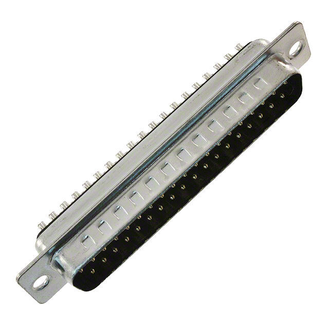
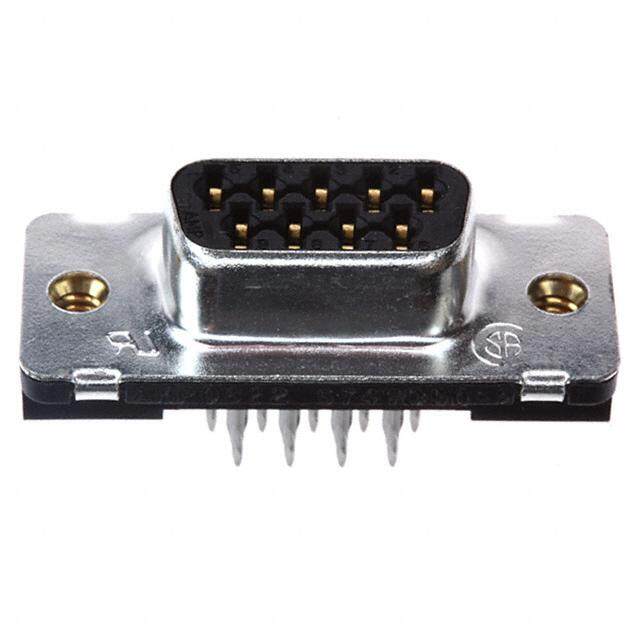
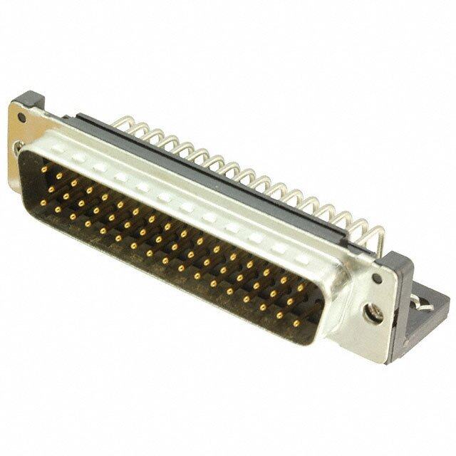
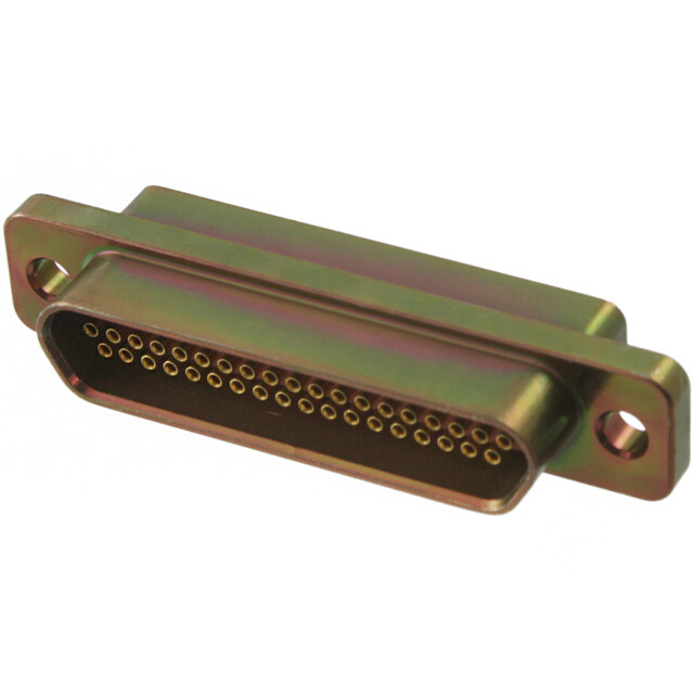
| 产品图片 | |
| 产品型号 | DAM-7W2P-K127 |
| rohs | 尚未确定供货商 / 不符合限制有害物质指令(RoHS)规范要求 |
| 产品系列 | Combo D®, D*M |
| 侵入防护 | - |
| 其它名称 | 053512-1475 |
| 包装 | 散装 |
| 外壳尺寸,连接器布局 | 2(DA,A)- 7W2 |
| 外壳材料 | 聚酯 |
| 外壳材料,镀层 | 钢,镀锡 |
| 安装类型 | 面板安装 |
| 工作温度 | -55°C ~ 125°C |
| 排数 | 2 |
| 标准包装 | 1 |
| 法兰特性 | 体座/外壳(无螺纹) |
| 特性 | 接地凹痕,屏蔽式 |
| 端接 | 焊杯 |
| 触头类型 | 信号和同轴或电源(未包括) |
| 触头镀层 | 金 |
| 触头镀层厚度 | 30µin (0.76µm) |
| 连接器样式 | D-Sub,组合式 |
| 连接器类型 | 插头,公引脚 |
| 针脚数 | 7(5 + 2 同轴或电源) |
| 颜色 | 黑 |
| 额定电压 | - |
| 额定电流 | 7.5A |


- 商务部:美国ITC正式对集成电路等产品启动337调查
- 曝三星4nm工艺存在良率问题 高通将骁龙8 Gen1或转产台积电
- 太阳诱电将投资9.5亿元在常州建新厂生产MLCC 预计2023年完工
- 英特尔发布欧洲新工厂建设计划 深化IDM 2.0 战略
- 台积电先进制程称霸业界 有大客户加持明年业绩稳了
- 达到5530亿美元!SIA预计今年全球半导体销售额将创下新高
- 英特尔拟将自动驾驶子公司Mobileye上市 估值或超500亿美元
- 三星加码芯片和SET,合并消费电子和移动部门,撤换高东真等 CEO
- 三星电子宣布重大人事变动 还合并消费电子和移动部门
- 海关总署:前11个月进口集成电路产品价值2.52万亿元 增长14.8%
.jpg)

.jpg)
PDF Datasheet 数据手册内容提取
None
Cannon, VEAM, BIW A Historical Achievement of Technology Leadership Defining and Championing Innovation Showcasing a portfolio of creativity, ITT’s “Engineered For Life” execution embraces products which have become ubiquitous in a broad collection of markets including: Military/Aerospace, Civil Aircraft, Industrial Instrumentation, Medical, Oil & Gas, Energy, Transportation, Telecom/Handset, Computer, Consumer, and Automotive. ITT’s rich interconnect history embraces contributions to both technological breakthroughs and social movements. With one of the industry’s broadest product offerings, ITT’s interconnect products have supported: • Every Free World space mission, bringing the universe to our doorstep. • Motion picture, radio, and television equipment, serving laughter and entertainment to millions. • Commercial and military communications systems, linking the voices of the world. • Computerized tools, reshaping the information highway. • Aircraft, rapid transit, and automobiles, mobilizing our expanding society. • Oil and natural gas production, powering the world’s economies. • Agricultural equipment, attacking the roots of world hunger. First Cannon pioneers Cannon creates Cannon originates Cannon develops Cannon establishes “Cannon Plug” sound and film Cannon creates “AN” military the first “D-Sub” the first “Micro” an aviation milestone +2000 4 Pole Power connectors with “K” series plugs connectors connectors through the expansion Connector the M Series connectors for of Rack and Panel DC-1’s Cannon develops Cannon pioneers Cannon partners connectors with the the first guided missle with technology BKAD/E Series The first commercial and power connectors The first aviation Tri-Service umbilical leaders to develop Breakaway circular & rack connector, the connectors the first complete 1980 Cannon connectors made possible the first panel connectors mother of modern fiber optic Technology radio microphones, the first black and white developed by day military systems Leadership television cameras as well as the first Cannon spec’s Chip-on-Flex color television equipment. Lean Cannon’s AF Cannon’s 1970 manufacturing Firewall connectors X connector is the PHD used in early first microminiature Internet deployed DC-3 transports audio connector 1960 systems Cannon founded by James Cannon 1950 Pioneering Quadrax technologies 1940 Cannon’s first entry into the Medical Engineered 1930 Electronics market solutions 1915 1920 Photo courtesy of The Academy of Stacking Motion Pictures, Arts and Sciences. The Power,Film, Aviation Military Telecom Space Medical, Growth Charting Beginning Commercial Transportation the Future
ITT Cannon ITT is a diversified leading manufacturer of highly prices. Our capabilities, especially in robotics, engineered critical components and customized computer-ized precision tooling, Kaizen Project technology solutions for the energy, Management, Six Sigma tools, and testing, give ITT the transportation and industrial markets. ITT’s most optimized global manufacturing footprint in the Cannon brand offers a product portfolio that interconnect industry. remains one of the most extensive in the industry. Continuous investment in technology, research The Custom Difference and investment have enabled us to provide new, innovative solutions to multiple end markets As the industry leader in harsh environment including Commercial Aerospace, Military & interconnect applications, ITT’s world class engineering Defense, Industrial and Medical. teams will work directly with our customers to design and develop cost effective solutions for their When you specify a Cannon cnnector, you can applications. In many cases we may modify one of our rely on a product designed, developed and standard designs to ensure a highly reliable solution manufactured to the highest quality and reliability where timing is critical. Yet, in those cases where a standards. This tradition of excellence is based on complete custom inter-connect solution is required, ITT ITT’s corporate culture of operating its businesses will work with our customer’s Engineers to design an under the principles of Six Sigma. At ITT, Six interconnect solution which will be cost effective yet Sigma is not just a quality philosophy but a highly reliable. As professional consultants, our complete corporate culture that drives the entire Engineering teams will provide a thorough systems and business. Our Value BasedManagement and mechanical analysis of any proposed solution. These Value Based Product Development systems are analyses provide our customers with sophisticated two cornerstones that allow for the development electrical signal and mechanical characterizations to of both leadership and product engineering determine the best solution for their application. principles, ensuring the correct industry leading products are developed to the accepted market RoHS Compliance Information driven lead times. These principles have allowed ITT to become the market leader in all of our ITT has implemented a strict parts control plan for all ITT business portfolios. electronics plants worldwide that allows the Cannonproduct portfolio to meet the requirements of European Union Directive 2002/95/EC better know as the Reduction of Hazardous Substances initiative. As Six Sigma Manufacturing appropriate, specific Cannon products may be ordered with an R prefix number which insures our customers will ITT operates manufacturing facilities in the receive RoHS compliant parts for their commercial United States, Germany, Italy, Mexico, China, electronics applications and equipment. Since most Japan and the UK, all of which have particular RoHS hazardous substances center around specific product area strengths allowing ITT to offer a metal plating and lead solder coatings, ITT's products for truly global footprint to our customers. Our RoHS compliance are avail-able in the following plating facilities are world class and accommodate full finishes: electroless nickel, stainless steel, Anodize over vertical integration utilizing the latest aluminum and Gold plating. It should be noted that gold manufacturing technologies including: automated plating would be recom-mended as the replacement for and robotic machining centers, Super Market tin-lead solder when ordering board mount connectors. manufacturing cells, Kanban pull systems, and automated electrical, mechanical, and optical test and inspection equipment. The combination of our manufacturing strength and our advanced manufacturing facilities allows ITT to offer products at market driven www.ittcannon.com
Cannon Combo D® Table of Contents Combo D* Introduction ................................................................................................................... 5-8 Combo D* PCB Connectors with Coaxial Contacts –90°, PCB Plug (sizes DE-DC), with metal bracket.......................................................................... 9 –90°, PCB Plug (size DD), with metal bracket. ................................................................................ 10 –90°, PCB Receptacle (sizes DE-DC) with metal bracket................................................................ 11 –90°, PCB Receptacle (sizes DD) with metal bracket...................................................................... 12 –European 90°, PCB Plug (size DE-DC), with bracket. ................................................................... 13 –European 90°, PCB Receptacle (size DE-DC), with bracket. ........................................................ 14 –Straight PCB Plug (sizes DE-DD) ................................................................................................. 15 –Straight PCB Receptacle (sizes DE-DD) ...................................................................................... 16 –Straight, European solder pins (sizes DE-DD) .............................................................................. 17 –Straight, European solder socket (sizes DE-DD) .......................................................................... 18 Combo D* PCB Connectors with High Power Contacts 40 A –90°, PCB Plug (sizes DE-DC), with metal bracket.......................................................................... 19 –90°, PCB Plug (size DD), with metal bracket. ................................................................................ 20 –90°, PCB Receptacle (sizes DE-DC) with metal bracket................................................................ 21 –90°, PCB Receptacle (sizes DD) with metal bracket..................................................................... 22 – 90°, PCB Plug, European footprint (sizes DE-DC), with bracket. ................................................. 23 – 90°, PCB Plug, European footprint (size DD), with bracket. ......................................................... 24 – 90°, PCB Receptacle, European footprint (sizes DE-DC), with bracket. ...................................... 25 – 90°, PCB Receptacle, European footprint (size DD), with bracket. .............................................. 26 –Straight PCB Plug (sizes DE-DC) ................................................................................................. 27 –Straight PCB Plug (size DD) ......................................................................................................... 28 –Straight PCB Receptacle (sizes DE-DC) ...................................................................................... 29 –Straight PCB Receptacle (size DD) .............................................................................................. 30 –Straight, European solder pins (sizes DE-DC) .............................................................................. 31 –Straight, European solder socket (sizes DE-DC) .......................................................................... 32 –Plug, Pressfit Termination .............................................................................................................. 33 –Receptacle, Pressfit Termination ................................................................................................... 34 Combo D* Connectors with empty Contact Cavities Size 8 – Plug, Solder cup (sizes DE – DC) ................................................................................................. 35 – Receptacle , Solder cup (Size DE-DC) ....................................................................................... 36 – Plug, Crimp connectors, without contacts (sizes DE – DD) .......................................................... 37 – Receptacle, Crimp connectors, without contacts (sizes DE – DD) ............................................... 38 – Crimp contacts size 20 ...............................................................................................................39-40 – Loose contacts size 8 .................................................................................................................41-53 Mounting Methods ... ....................................................................................................................... .. 59 Contact Arrangements ................................................................................................................. 61-62 PCB Holes Pattern ....................................................................................................................... 66-98 Tooling .............................................................................................................................................. 99 Product Safety Information .............................................................................................................. 101 www.ittcannon.com 4
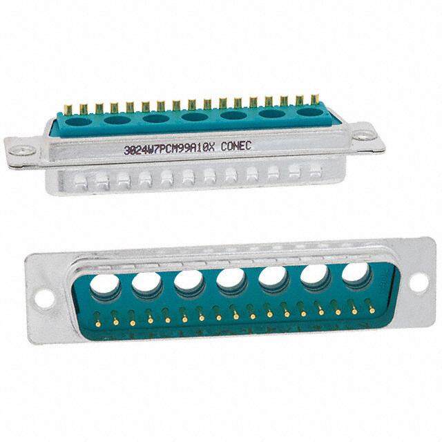
Cannon Combo D® Applications Combination D Subminiature connectors for the advan- • Video Coaxial Transmission (75 (cid:0)) tages of an industry standard shield I/O interconnect, with • RF and Telecom Transmission (50 (cid:0)) the flexibility of a customized special, designed for any • Power interconnects (Up to 40 A) application. Product Features • Standard and European Footprints This connector system is ideal for applications that require • Pre-installed 75 (cid:0)/50 (cid:0)Coaxial or High Power contacts (One optimization of space while improving overall shielding. Combo D®accomplishes this by combining multiple Part Number) • Vertical Standoffs or 90° Brackets interconnect types into one fully shielded product, • 90° or Straight PCB decreasing the number I/O interfaces and reducing the • PC Boards up to 3,2 (.125) Thick possibility of EMI/RFI leakage. • PCB Variants Available with Boardlocks and/or Screw Locks (#4-40 or M3) • Fiber Optics (PhD) • High Voltage up to 2800 VAC Specifications Standard materials & finishes Temperature Rating –55°C to 125°C Coaxial VSWR Less than 1.40 + .03F for F up to 1GHz Signal Contact Current Rating 7.5 A current capacity Coaxial Insertion Loss .2dB loss at 1 GHz Signal Contact Resistance 55 millivolt max. at 7.5 test current High Power current Rating Up to 40 A Signal Contact High Power Dielectric Withstanding Voltage 1250 VAC at Sea Level Dielectric Withstanding Voltage 1000 VAC at Sea Level Coaxial Current Rating 5 A High Voltage Current Rating 5 A Coaxial Dielectric Withstanding Voltage 1000 VAC at Sea Level High Voltage Contact Coaxial Impedance 75 (cid:0)or 50 (cid:0) Dielectric Withstanding Voltage 2800 V at Sea Level Materials and Finishes Connector Assembly Description Material Finish/Treatment Shell Carbon Steel Tin-Nickel (Industrial), Chromate/Zinc (Military)* Insulator Black Polyester, UL 94V-0 None Pin Contact Copper Alloy Gold over Nickel Socket Contact Copper Alloy Gold over Nickel Standoff Steel Trivalent Chromate over Zinc Bracket Steel Tin Rivnut Steel Tin Boardlock Copper Alloy Tin Coaxial/High Power/High Voltage Contact Assemblies Contacts and outer shells Copper Alloy Gold over Nickel Ring, Retaining Copper Alloy Nickel Insulator (Coaxial only) Teflon None Insulator (High Voltage only) Thermoplastic none * Cadmium and Stainless Also Available Dimensions shown in mm Specifications and dimensions subject to change www.ittcannon.com 5
Cannon Combo D® Non Magnetic / Low Outgassing Materials and Finishes Connector Assembly (Shells- Gold over Copper) (Modifier NMBK52) Shell Brass per QQ-B-613 Gold 50 microinches min., thickness per MIL-G-45204, Type II, Class1 over copper per MIL-C-14550 Insulator Polycyclohexle Dimethyl, Terephthalate None or Polyphenylene, Sulfide co-polymer per 24308-Style white or black in color Float Mount, Brackets, Captive Nuts Hardware Brass Gold Coaxial/High Power/High Voltage Contact Assemblies Outer Coaxial Shell Copper Alloy Gold microinches min.thickness per MIL-G-45204, Type II, Class 1 over copper per MIL-C-14550 Center Coaxial Contact Copper Alloy Gold microinches min.thickness per MIL-G-45204, Type II, Class 1 over copper per MIL-C-14550 Insulator (Coaxial only) Teflon None Insulator (Coaxial Only) Teflon None Retaining Ring Copper alloy Gold High Power Contact Copper alloy Gold microinches min.thickness per MIL-G-45204, Type II, Class 1 over copper per MIL-C-14550 Connector Assembly (Shells- Yellow Chromate over Cadmium) (Modifier “NMB”) Shell Brass per QQ-B-613 Yellow chromate over cadmium QQ-P-46,Type II, Class 2 Insulator Polycyclohexle Dimethyl, Terephthalate None or Polyphenylene, Sulfide co-polymer per 24308-Style, white or black in color Contact Copper Alloy Gold 50 microinches min. thickness per MIL-G-45204, Type II, Class 1 over copper per MIL-C-14550 Float Mount, Brackets, Captive Nuts Hardware Brass Yellow chromate over cadmium QQ-P-416, Type II, Class 2 Dimensions shown in mm Specifications and dimensions subject to change www.ittcannon.com 6
Cannon Combo D® Ordering Information Designator Selection For Crimp, Solder Cup and PCB Type Combo-D’s Typical Part Number: DBM C 13C3 S J A197 Product Family Designator Shell Modifier (Standard) = Carbon steel, yellow chromate over zinc D*M = Solder Cup Industrial & Space/Non-Magnetic Version A197 = Carbon steel, tin-nickel plating (receptacles only) D*MM= Military/Hi-Rel Solder Cupp version (50 micro-inch (RoHS) gold contact plating) K87 = Carbon steel, tin-nickel plating (plugs only) D*A = Crimp Version (RoHS) F225 = Stainless steel shells **Hardware Modifier NMBK52 = Space/Non-Magnetic version, gold plated =0.120” (3,05mm) Through Hole A101 = Carbon Steel, Cadmium plating C =90° Metal Bracket, 4-40 Fastener, & Boardlock D =90° Metal Bracket, 4-40 Fastener and 4-40 Screwlock E =4-40 Clinchnut PC Tall Modifier (Standard) G =90° Metal Bracket, 4-40 Fastener, 4-40 Screwlock, Boardlock = Solder cup (D*M/D*MM; Crimp, D*A) H =.300” (7.6mm) Standoff, 4-40 Screwlock J = 90° Std. PCB signal contact (.170” lg by .030” (cid:0)) J =90° Metal Bracket, Fastener, M-3 Fastener, Boardlock N = Straight Std. PCB signal contact (.178 lg by .030 (cid:0)) K =0.162” (4,11mm) Through Hole V = 90° Euro PCB signal contact (.157” lg by .024 (cid:0)) L =90° Metal Bracket, M-3 Fastener, Boardlock Y = Straight Euro PCB signal contact (.178” lb by .024” (cid:0)) N =.300” (7.6mm) Standoff, 4-40 Screwlock, Boardlock O =90° Metal Bracket, Fastener, M-3 Screwlock Gender P =90° Metal Bracket, 4-40 Fastener P = Male Plug, Pin Q =.300” (7.6mm) M-3 Standoff S = Female Receptacle, Socket S =90° Metal Bracket, M-3 Fastener T =.300” (7.6mm) M-3 Standoff Layouts Combo-D U =.300” (7.6mm) Standoff, M-3 Screwlock, Boardlock V =.300” (7.6mm) 4-40 Standoff E- 5W1, 2W2, 2WK2 W=.300” (7.6mm) Standoff, M-3 Screwlock A- 3W3, 3WK3, 7W2, 11W1 X =M-3 Clinchnut B- 5W5, 9W4, 13W3, 17W2, 21W1 Y =Dual Float Mount C- 8W8, 13W6, 17W5, 21WA4, 25W3, Z =.300” (7.6mm) 4-40 Standoff, Boardlock 27W2 * =Shell Sizes are E, A, B, C, D D- 24W7, 36W4, 43W2, 47W1 **= Hardware Modifier not allowed with Non-Magnetic, Low Outgassing Combo-D Combo-D Size 8 Contact Designators: W**= w/o Contacts (letters below denote with contacts) C = 75 Ohm Coax Contacts Installed X = 50 Ohm Coax Contacts Installed H = High Power Installed (US Standard) P = High Power Installed (European) V = High Voltage Installed (Cable and PCB only) R = Mini Hi Power 90° installed ** All cable side connectors use the “W” designation (without contacts) for ordering and have size and contacts ordered sepa- rately Dimensions shown in mm Specifications and dimensions subject to change www.ittcannon.com 7
Cannon Combo D® European Ordering Information Designator Selection Combo D European Versions Typical Part Number: DBM E- 9C4 P-P00-1A5N- A191-K87-146 Product Family Designator D*M = Combo D PCB Mounting Method = shell size E, A, B, C and D 146 = Pushfit for PCB hold diameter 3.0, 90° version only 162 = Pushfit for PCB hold diameter 3.2, 90° version only Hardware Modifier without code = 3,05mm” (.120 in.) Through Hole Plating Modification E = 4-40 Clinchnut, solder cup, solder pin straight and 1A0N without code = Tellow chromate over zinc on shells N = 7.66 mm (.300 in.) with 4-40 post and pushfit, only OL4 A197 = Tin on shells Q = 7.66 mm (.300 in.) M3 with pushfit, only OL4 K87 = Tin with dimples on shells (pin only) T = 7.66 mm (.300 in.) M3 standoff, only OL4 U = 7.66 mm (.300 in.) M3 post and pushfit, only OL4 V = 7.66 mm (.300 in.) 4-40 with pushfit, only OL4 Contact Finishes X = M-3 Clinchnut, solder cup, solder pin straight and 1A0N without code = performance class 3 (50 mating cycles) Y = Dual Float Mount, only solder cup A191 = performance class 2 (200 mating cycles) Euro standard Z =.7.66 mm (.300 in.) 4-40 with pushfit, only OL4 A190 = performance class 1 (500 mating cycles) Layout (Total # of contacts + # of Size 8 Cavities) Tail Modifier without code = Non Combo (9, 15, 25, 37, 50) [OL2] = No standard, please call factory W = Empty size 8 Cavities = Solder cup (size 8 contacts not loaded on these C = 75 Ohm Coax installed (straight or 90°) versions) X = 50 Ohm Coax installed (straight or 90°) OL4 = Solder pin straight H = High power installed (straight) 1A0N = without mouting bracket, hole dia. 3.05 mm P = High power installed (Euro, 90° only) 1A5N = plastic bracket with bushing dia. 3.05 mm V = High voltage installed (available in straight PC only 1A6N = plastic bracket with post 4-40 G = Guide pin or guide socket installed 1A7N = metal bracket and captive nut 4-40 1A8N = metal bracket with post 4-40 Gender 1A9N = metal bracket and captive nut M3 P = Male (plug, pin) 1ADN = plastic bracket with grounding bracket and bushing S = Female (receptacle, socket) dia. 3.05 mm 1AFN = metal bracket with bushing dia. 3.05 mm Code only applicable for Pressfit High power #8 contacts 1AGN = plastic bracket with grounding bracket and post M3 P00 = Pessfit High power PCB dia 2,9 mm 1AHN = metal bracket with post M3 P01 = Pessfit High power PCB dia 3,1 mm 1AJN = plastic bracket with grounding bracket and post P02 = Pessfit High power PCB dia 3,5 mm 4-40 1APN = plastic bracket with post M3 1ATN = plastic bracket and captive nut M3 1AUN = plastic bracket and captive nut 4-40 1AVN = plastic bracket with grounding bracket and captive nut M3 1AWN= plastic bracket with grounding bracket and captive nut 4-40 1AEN = 90° low profile metal bracket captive nut M3 1AAN = 90° low profile metal bracket captive nut 4-40 1ABN = 90° low profile metal bracket post M3 1ACN = low profile metal bracket post 4-40 1ALN = low profile metal bracket with buhing dia. 3.05 mm Dimensions shown in mm Specifications and dimensions subject to change www.ittcannon.com 8
Cannon Combo D® Coax 90° PCB Plug DE-DC Coaxial 90° PCB Plug, sizes DE – DC, with metal bracket INDUSTRIAL – US INDUSTRIAL – EU** MILITARY/HI-REL – US NON-MAGNETIC- LOW OUTGASSING – US*** 75 Ohm* coax inserted with 75 Ohm* coax inserted with 50 Ohm* coax inserted with 50 Ohm* coax inserted with US footprint metal bracket EU footprint metal bracket US footprint metal bracket US footprint metal bracket and UNC 4-40 captive nut and UNC 4-40 captive nut and UNC 4-40 screw lock and UNC 4-40 screw lock Shell Layout P/N without P/N with P/N without P/N with P/N without P/N with P/N with P/N with size Boardlock Boardlock Boardlock Boardlock Boardlock Boardlock Cadmium Plating Gold Plating DE 2W2 DEMP2C2P-JK87 DEMC2C2P-JK87 DEMP2C2P-VK87 DEMC2C2P-VK87 DEMMD2X2P-J DEMMG2X2P-J DEM2X2P-JNMB DEM2X2P-JNMBK52 DE 2WK2 DEMP2CK2P-JK87 DEMC2CK2P-JK87 DEMP2CK2P-VK87 DEMC2CK2P-VK87 DEMMD2XK2P-J DEMMG2XK2P-J DEM2XK2P-JNMB DEM2XK2P-JNMBK52 DE 5W1 DEMP5C1P-JK87 DEMC5C1P-JK87 DEMP5C1P-VK87 DEMC5C1P-VK87 DEMMD5X1P-J DEMMG5X1P-J DEM5X1P-JNMB DEM5X1P-JNMBK52 DA 7W2 DAMP7C2P-JK87 DAMC7C2P-JK87 DAMP7C2P-VK87 DAMC7C2P-VK87 DAMMD7X2P-J DAMMG7X2P-J DAM7X2P-JNMB DAM7X2P-JNMBK52 DA 11W1 DAMP11C1P-JK87 DAMC11C1P-JK87 DAMP11C1P-VK87 DAMC11C1P-VK87 DAMMD11X1P-J DAMMG11X1P-J DAM11X1P-JNMB DAM11X1P-JNMBK52 DA 3W3 DAMP3C3P-JK87 DAMC3C3P-JK87 DAMP3C3P-VK87 DAMC3C3P-VK87 DAMMD3X3P-J DAMMG3X3P-J DAM3X3P-JNMB DAM3X3P-JNMBK52 DA 3WK3 DAMP3CK3P-JK87 DAMC3CK3P-JK87 DAMP3CK3P-VK87 DAMC3CK3P-VK87 DAMMD3XK3P-J DAMMG3XK3P-J DAM3XK3P-JNMB DAM3XK3P-JNMBK52 DB 5W5 DBMP5C5P-JK87 DBMC5C5P-JK87 DBMP5C5P-VK87 DBMC5C5P-VK87 DBMMD5X5P-J DBMMG5X5P-J DBM5X5P-JNMB DBM5X5P-JNMBK52 DB 9W4 DBMP9C4P-JK87 DBMC9C4P-JK87 DBMP9C4P-VK87 DBMC9C4P-VK87 DBMMD9X4P-J DBMMG9X4P-J DBM9X4P-JNMB DBM9X4P-JNMBK52 DB 13W3 DBMP13C3P-JK87 DBMC13C3P-JK87 DBMP13C3P-VK87 DBMC13C3P-VK87 DBMMD13X3P-J DBMMG13X3P-J DBM13X3P-JNMB DBM13X3P-JNMBK52 DB 17W2 DBMP17C2P-JK87 DBMC17C2P-JK87 DBMP17C2P-VK87 DBMC17C2P-VK87 DBMMD17X2P-J DBMMG17X2P-J DBM17X2P-JNMB DBM17X2P-JNMBK52 DB 21W1 DBMP21C1P-JK87 DBMC21C1P-JK87 DBMP21C1P-VK87 DBMC21C1P-VK87 DBMMD21X1P-J DBMMG21X1P-J DBM21X1P-JNMB DBM21X1P-JNMBK52 DC 8W8 DCMP8C8P-JK87 DCMC8C8P-JK87 DCMP8C8P-VK87 DCMC8C8P-VK87 DCMMD8X8P-J DCMMG8X8P-J DCM8X8P-JNMB DCM8X8P-JNMBK52 DC 13W6 DCMP13C6P-JK87 DCMC13C6P-JK87 DCMP13C6P-VK87 DCMC13C6P-VK87 DCMMD13X6P-J DCMMG13X6P-J DCM13X6P-JNMB DCM13X6P-JNMBK52 DC 17W5 DCMP17C5P-JK87 DCMC17C5P-JK87 DCMP17C5P-VK87 DCMC17C5P-VK87 DCMMD17X5P-J DCMMG17X5P-J DCM17X5P-JNMB DCM17X5P-JNMBK52 DC 21WA4 DCMP21CA4P-JK87 DCMC21CA4P-JK87 DCMP21CA4P-VK87 DCMC21CA4P-VK87 DCMMD21XA4P-J DCMMG21XA4P-J DCM21CX4P-JNMB DCM21XA4P-JNMBK52 DC 25W3 DCMP25C3P-JK87 DCMC25C3P-JK87 DCMP25C3P-VK87 DCMC25C3P-VK87 DCMMD25X3P-J DCMMG25X3P-J DCM25X3P-JNMB DCM25X3P-JNMBK52 DC 27W2 DCMP27C2P-JK87 DCMC27C2P-JK87 DCMP27C2P-VK87 DCMC27C2P-VK87 DCMMD27X2P-J DCMMG27X2P-J DCM27X2P-JNMB DCM27X2P-JNMBK52 C X * For 50 ohm coaxial inserts replace C with X, e.g.:DCM13 6P-J becomes DCM13 6P-J. **For M-3 hardware, see part number designator, page 7. *** Hardware Modifier not allowed with Non Magnetic/ Low Outgassing Combo-D- Contact factory for more information Plug • For contact cavity arrangements, see page 61. • For pcb hole pattern, see pages 67-68. • For mounting methods, see pages 59-60. For 50 ohm coaxial version, see readers resource section page 63.. Dimensions Shell A B C D E F W W L size ± 0,38 (.015) ± 0,13 (.005) ± 0,13 (.005) ± 0,13 (.005) ± 0,38 (.015) ± 0,25 (.010) ± 0,368 (.0145) ± 0,41 (.016) ± 0,25 (.010) DE 30,81 (1.213) 16,92 (.665) 24,99 (.984) 8,36 (.329) 12,55 (.494) 10,72 (.422) 6,693 (.2635) — 0,76 (.030) DA 39,14 (1.541) 25,25 (.994) 33,32 (1.312) 8,36 (.329) 12,55 (.494) 10,72 (.422) 6,693 (.2635) — 0,76 (.030) DB 53,04 (2.088) 38,96 (1.534) 47,04 (1.852) 8,36 (.329) 12,55 (.494) 10,82 (.426) — 6,84 (.269) 0,99 (.039) DC 69,32 (2.729) 55,42 (2.182) 63,50 (2,500) 8,36 (.329) 12,55 (.494) 10,82 (.426) — 6,84 (.269) 0,99 (.039) Dimensions shown in mm Specifications and dimensions subject to change www.ittcannon.com 9
Cannon Combo D® Coax 90° PCB Plug DD Coaxial 90° PCB Plug, size DD, with metal bracket INDUSTRIAL – US INDUSTRIAL – EU** MILITARY/HI-REL – US NON-MAGNETIC/LOW OUTGASSING-EU*** 75 Ohm* coax inserted with 75 Ohm* coax inserted with 50 Ohm* coax inserted with 50 Ohm* coax inserted with Coaxial 90°PCB (Size DD) US footprint metal bracket EU footprint metal bracket US footprint metal bracket US footprint metal bracket and UNC 4-40 captive nut and UNC 4-40 captive nut and UNC 4-40 screw lock and UNC 4-40 screw lock Shell Layout P/N without P/N with P/N without P/N with P/N without P/N with P/N with P/N with size Boardlock Boardlock Boardlock Boardlock Boardlock Boardlock Cadmium Plating Gold Plating DD 24W7 DDMP24C7P-JK87 DDMC24C7P-JK87 DDMP24C7P-VK87 DDMC24C7P-VK87 DDMMD24X7P-J DDMMG24X7P-J DDM24X7P-JNMB DDM24X7P-JNMBK52 DD 36W4 DDMP36C4P-JK87 DDMC36C4P-JK87 DDMP36C4P-VK87 DDMC36C4P-VK87 DDMMD36X4P-J DDMMG36X4P-J DDM36X4P-JNMB DDM36X4P-JNMBK52 DD 43W2 DDMP43C2P-JK87 DDMC43C2P-JK87 DDMP43C2P-VK87 DDMC43C2P-VK87 DDMMD43X2P-J DDMMG43X2P-J DDM43X2P-JNMB DDM43X2P-JNMBK52 DD 47W1 DDMP47C1P-JK87 DDMC47C1P-JK87 DDMP47C1P-VK87 DDMC47C1P-VK87 DDMMD47X1P-J DDMMG47X1P-J DDM47X1P-JNMB DDM47X1P-JNMBK52 C X * For 50 ohm coaxial inserts replace C with X, e.g.:DCM13 6P-J becomes DCM13 6P-J. **For M-3 hardware, see part number designator, page 7. *** Hardware Modifier not allowed with Non Magnetic/ Low Outgassing Combo-D- Contact factory for more information PPlulugg • For contact cavity arrangements, see page 61. • For pcb hole pattern, see pages 67-68. • For mounting methods, see pages 59-60. SCREW LOCK #4-40 UNC 6,50± 0,25 (.256± .010) W F 11,53± 0,25 10,06 (.454± .010) (.396) 13,74 RIVNUT (.541) #4-40 UNC 5,68 (.224) BRACKET, METAL 4,33± 0,38 2,84 (.170± .015) (.112) Engaging Face Screw lock, boardlock, and coaxial contact removed for clarity 10° L E D 11,94± 0,33 (.470± .013) 2,54 (.100) 2,92 Ø 0,51 BOARDLOCK (0.0,8322) Ø(. 003,706) (.115) (.020) 3,89 (.153) B 0,56 MIN (.023) C A Screw lock, boardlock, and signal contacts removed for clarity US version shown – for EU version, please contact factory. NNootete:: DDimimeennssioionn v vaarireiess w witihth a altleternrnaatete b brraacckkeet t ccoonnffigiguurraattioionn,, sseeee RReeaaddeerr’’ss RReessoouurrccee ppaaggee 62246.. For 50 ohm coaxial version, see readers resource section, page 63. Dimensions Shell A B C D E F W L size ± 0,38 (.015) ± 0,13 (.005) ± 0,13 (.005) ± 0,13 (.005) ± 0,38 (.015) ± 0,25 (.010) ± 0,41 (.015) ± 0,25 (.010) DD 66,93 (2.635) 52,81 (2.079) 61,11 (2,406) 11,07 (.436) 15,37 (.605) 10,82 (.426) 6,84 (.269) 0,99 (.039) Dimensions shown in mm Specifications and dimensions subject to change www.ittcannon.com 10
Cannon Combo D® Coax 90° PCB Receptacle DE-DC Coaxial 90° PCB Receptacle, sizes DE – DC, with metal bracket INDUSTRIAL – US INDUSTRIAL – EU** MILITARY/HI-REL – US NON-MAGNETIC/LOW OUTGASSING – US*** 75 Ohm* coax inserted with 75 Ohm* coax inserted with 50 Ohm* coax inserted with 50 Ohm* coax inserted with US Footprint metal bracket EU Footprint metal bracket US Footprint metal bracket US Footprint metal bracket and UNC 4-40 captive nut and UNC 4-40 captive nut and UNC 4-40 screw lock and UNC 4-40 screw lock Shell Layout P/N without P/N with P/N without P/N with P/N without P/N with P/N with P/N with size Boardlock Boardlock Boardlock Boardlock Boardlock Boardlock Cadmium Plating Gold Plating DE 2W2 DEMP2C2S-JA197 DEMC2C2S-JA197 DEMP2C2S-VA197 DEMC2C2S-VA197 DEMMP2X2S-J DEMMC2X2S-J DEM2X2S-JNMB DEM2X2S-JNMBK52 DE 2WK2 DEMP2CK2S-JA197 DEMC2CK2S-JA197 DEMP2CK2S-VA197 DEMC2CK2S-VA197 DEMMP2XK2S-J DEMMC2XK2S-J DEM2XK2S-JNMB DEM2XK2S-JNMBK52 DE 5W1 DEMP5C1S-JA197 DEMC5C1S-JA197 DEMP5C1S-VA197 DEMC5C1S-VA197 DEMMP5X1S-J DEMMC5X1S-J DEM5X1S-JNMB DEM5X1S-JNMBK52 DA 7W2 DAMP7C2S-JA197 DAMC7C2S-JA197 DAMP7C2S-VA197 DAMC7C2S-VA197 DAMMP7X2S-J DAMMC7X2S-J DAM7X7S-JNMB DAM7X2S-JNMBK52 DA 11W1 DAMP11C1S-JA197 DAMC11C1S-JA197 DAMP11C1S-VA197 DAMC11C1S-VA197 DAMMP11X1S-J DAMMC11X1S-J DAM11X1S-JNMB DAM11X1S-JNMBK52 DA 3W3 DAMP3C3S-JA197 DAMC3C3S-JA197 DAMP3C3S-VA197 DAMC3C3S-VA197 DAMMP3X3S-J DAMMC3X3S-J DAM3X3S-JNMB DAM3X3S-JNMBK52 DA 3WK3 DAMP3CK3S-JA197 DAMC3CK3S-JA197 DAMP3CK3S-VA197 DAMC3CK3S-VA197 DAMMP3XK3S-J DAMMC3XK3S-J DAM3XK3S-JNMB DAM3XK3S-JNMBK52 DB 5W5 DBMP5C5S-JA197 DBMC5C5S-JA197 DBMP5C5S-VA197 DBMC5C5S-VA197 DBMMP5X5S-J DBMMC5X5S-J DBM5X5S-JNMB DBM5X5S-JNMBK52 DB 9W4 DBMP9C4S-JA197 DBMC9C4S-JA197 DBMP9C4S-VA197 DBMC9C4S-VA197 DBMMP9X4S-J DBMMC9X4S-J DBM9X4S-JNMB DBM9X4S-JNMBK52 DB 13W3 DBMP13C3S-JA197 DBMC13C3S-JA197 DBMP13C3S-VA197 DBMC13C3S-VA197 DBMMP13X3S-J DBMMC13X3S-J DBM13X3S-JNMB DBM13X3S-JNMBK52 DB 17W2 DBMP17C2S-JA197 DBMC17C2S-JA197 DBMP17C2S-VA197 DBMC17C2S-VA197 DBMMP17X2S-J DBMMC17X2S-J DBM17X2S-JNMB DBM17X2S-JNMBK52 DB 21W1 DBMP21C1S-JA197 DBMC21C1S-JA197 DBMP21C1S-VA197 DBMC21C1S-VA197 DBMMP21X1S-J DBMMC21X1S-J DBM21X1S-JNMB DBM21X1S-JNMBK52 DC 8W8 DCMP8C8S-JA197 DCMC8C8S-JA197 DCMP8C8S-VA197 DCMC8C8S-VA197 DCMMP8X8S-J DCMMC8X8S-J DCM8X8S-JNMB DCM8X8S-JNMBK52 DC 13W6 DCMP13C6S-JA197 DCMC13C6S-JA197 DCMP13C6S-VA197 DCMC13C6S-VA197 DCMMP13X6S-J DCMMC13X6S-J DCM13X6S-JNMB DCM13X6S-JNMBK52 DC 17W5 DCMP17C5S-JA197 DCMC17C5S-JA197 DCMP17C5S-VA197 DCMC17C5S-VA197 DCMMP17X5S-J DCMMC17X5S-J DCM17X5S-JNMB DCM17X5S-JNMBK52 DC 21WA4 DCMP21CA4S-JA197 DCMC21CA4S-JA197 DCMP21CA4S-VA197 DCMC21CA4S-VA197 DCMMP21XA4S-J DCMMC21XA4S-J DCM21XA4S-JNMB DCM21XA4S-JNMBK52 DC 25W3 DCMP25C3S-JA197 DCMC25C3S-JA197 DCMP25C3S-VA197 DCMC25C3S-VA197 DCMMP25X3S-J DCMMC25X3S-J DCM25X3S-JNMB DCM25X3S-JNMBK52 DC 27W2 DCMP27C2S-JA197 DCMC27C2S-JA197 DCMP27C2S-VA197 DCMC27C2S-VA197 DCMMP27X2S-J DCMMC27X2S-J DCM27X2S-JNMB DCM27X2S-JNMBK52 C X * For 50 ohm coaxial inserts replace C with X, e.g.:DCM13 6S-J becomes DCM13 6S-J. **For M-3 and other hardware options, see part number designator, page 7. *** Hardware Modifier not allowed with Non Magnetic/ Low Outgassing Combo-D- Contact factory for more information Receptacle • For contact cavity arrangements, see page 62. • For pcb hole pattern, see pages 69-71. • For mounting methods, see pages 59-60. US version shown – for EU version, please see page 14. For 50 ohm coaxial version, see readers resource section, page 63. Dimensions Shell A B C D E F W L size ± 0,38 (.015) ± 0,13 (.005) ± 0,13 (.005) ± 0,13 (.005) ± 0,38 (.015) ± 0,25 (.010) ± 0,38 (.015) ± 0,25 (.010) DE 30,81 (1.213) 16,33 (.643) 24,99 (.984) 7,90 (.311) 12,55 (.494) 10,90 (.429) 6,94 (.273) 0,76 (.030) DA 39,14 (1.541) 24,65 (.971) 33,32 (1.312) 7,90 (.311) 12,55 (.494) 10,90 (.429) 6,94 (.273) 0,76 (.030) DB 53,04 (2.088) 38,38 (1.511) 47,04 (1.852) 7,90 (.311) 12,55 (.494) 10,90 (.429) 6,94 (.273) 0,76 (.030) DC 69,32 (2.729) 54,84 (2.159) 63,50 (2,500) 7,90 (.311) 12,55 (.494) 10,90 (.429) 6,94 (.273) 0,76 (.030) Dimensions shown in mm Specifications and dimensions subject to change www.ittcannon.com 11
Cannon Combo D® Coax 90° PCB Receptacle DD Coaxial 90° PCB Receptacle, size DD, with metal bracket INDUSTRIAL – US INDUSTRIAL – EU** MILITARY/HI-REL – US NON-MAGNETIC/LOW OUTGASSING – US*** 75 Ohm* coax inserted with 75 Ohm* coax inserted with 75 Ohm* coax inserted with 75 Ohm* coax inserted with Coaxial 9US0 F°ooPtprCint Bme t(aSl birazceke tD D) EU Footprint metal bracket US Footprint metal bracket US Footprint metal bracket and UNC 4-40 captive nut and UNC 4-40 captive nut and UNC 4-40 screw lock and UNC 4-40 screw lock Shell Layout P/N without P/N with P/N without P/N with P/N without P/N with P/N with P/N with size Boardlock Boardlock Boardlock Boardlock Boardlock Boardlock Cadmium Plating Gold Plating DD 24W7 DDMP24C7S-JA197 DDMC24C7S-JA197 DDMP24C7S-VA197 DDMC24C7S-VA197 DDMMD24X7S-J DDMMG24X2S-J DDM24X7S-JNMB DDM24X7S-JNMBK52 DD 36W4 DDMP36C4S-JA197 DDMC36C4S-JA197 DDMP36C4S-VA197 DDMC36C4S-VA197 DDMMD36X4S-J DDMMG36X1S-J DDM36X4S-JNMB DDM36X4S-JNMBK52 DD 43W2 DDMP43C2S-JA197 DDMC43C2S-JA197 DDMP43C2S-VA197 DDMC43C2S-VA197 DDMMD43X2S-J DDMMG43X2S-J DDM43X7S-JNMB DDM43X2S-JNMBK52 DD 47W1 DDMP47C1S-JA197 DDMC47C1S-JA197 DDMP47C1S-VA197 DDMC47C1S-VA197 DDMMD47X1S-J DDMMG47X1S-J DDM47X1S-JNMB DDM47X1S-JNMBK52 C X * For 50 ohm coaxial inserts replace C with X, e.g.:DCM13 6 becomes DCM13 6S-JA197 **For M-3 and other hardware options, see part number designator, page 7. *** Hardware Modifier not allowed with Non Magnetic/ Low Outgassing Combo-D- Contact factory for more information Receptacle • For contact cavity arrangements, see page 62. Receptacle • For pcb hole pattern, see pages 69-71. • For mounting methods, see pages 59-60. SCREW LOCK 6,50± 0,25 #4-40 UNC (.256± .010) W F 11,53± 0,25 10,06 (.454± .010) (.396) 13,74 (.541) RIVNUT 5,68 #4-40 UNC (.224) BRACKET, 4,33± 0,38 METAL 2,84 (.112) (.170± .015) Screw lock, boardlock, and coaxial contacts removed for clarity Engaging Face 10° L D 2,54 11,94± 0,33 E (.100) (.470± .013) 2,92 0,82 Ø 0,76 BOARDLOCK Ø 0,51 3,89 (.153) (.115) (.032) (.030) (.020) MIN B 0,56 (.023) C A Screw lock, boardlock, and signal contacts removed for clarity US version shown – for EU version, please see contact factory. NNotoet:e: DDiimmeennssiioonn vvaarriieess wwiitthh aalltteerrnnaattee bbrraacckkeett ccoonnffiigguurraattiioonn,, sseeee RReeaaddeerr’s’s Resource page 226. For 50 ohm coaxial version, see readers resource section, page 63. Resource page 64. Dimensions Shell A B C D E F W L size ± 0,38 (.015) ± 0,13 (.005) ± 0,13 (.005) ± 0,13 (.005) ± 0,38 (.015) ± 0,25 (.010) ± 0,38 (.015) ± 0,25 (.010) DD 66,93 (2.635) 52,42 (2.064) 61,11 (2,406) 10,74 (.423) 15,37 (.605) 10,90 (.429) 6,94 (.273) 0,76 (.030) Dimensions shown in mm Specifications and dimensions subject to change www.ittcannon.com 12
Cannon Combo D® European Coax 90° PCB Plug DE-DC Coaxial 90° PCB Plug, sizes DE – DC, with bracket 75 Ohm part numbers with bracket and captive nut M3 75 Ohm part numbers with bracket with 75 Ohm part number with bracket with post M3 bushing dia. 3,05 Shell Layout Plastic Metal Plastic Metal Plastic Metal size Bracket Bracket Bracket Bracket Bracket Bracket DE 2W2 DEM-2C2P-1ATN-A191-K87 DEM02C2P-1A9N-A191-K87 DEM-2C2P-1A5N-A191-K87 DEM-2C2P-1AFN-A191-K87 DEM-2C2P-APN-A191-K87 DEM-2C2P-1AHN-A191-K87 DE 2WK2 DEM-2CK2P-1ATN-A191-K87 DEM02CK2P-1A9N-A191-K87 DEM-2CK2P-1A5N-A191-K87 DEM-2CK2P-1AFN-A191-K87 DEM-2CK2P-APN-A191-K87 DEM-2CK2P-1AHN-A191-K87 DE 5W1 DEM-5C1P-1ATN-A191- K87 DEM-5C1P-1A9N-A191-K87 DEM-5C1P-1A5N-A191-K87 DEM-5C1P-1AFN-A191-K87 DEM-5C1P-APN-A191-K87 DEM-5C1P-1AHN-A191-K87 DA 7W2 DAM-7C2P-1ATN-A191-K87 DAM-7C2P-1A9N-A191-K87 DAM-7C2P-1A5N-A191-K87 DAM-7C2P-1AFN-A191-K87 DAM-7C2P-1APN-A191-K87 DAM-7C2P-1AHN-A191-K87 DA 11W1 DAM-11C1P-1ATN-A191-K87 DAM-11C1P-1A9N-A191-K87 DAM-11C1P-1A5N-A191-K87 DAM-11C1P-1AFN-A191-K87 DAM-11C1P-1APN-A191-K87 DAM-11C1P-1AHN-A191-K87 DA 3W3 DAM-3C3P-1ATN-A191-K87 DAM-3C3P-1A9N-A191-K87 DAM-3C3P-1A5N-A191-K87 DAM-3C3P-1AFN-A191-K87 DAM-3C3P-1APN-A191-K87 DAM-3C3P-1AHN-A191-K87 DA 3WK3 DAM-3CK3P-1ATN-A191-K87 DAM-3CK3P-1A9N-A191-K87 DAM-3CK3P-1A5N-A191-K87 DAM-3CK3P-1AFN-A191-K87 DAM-3CK3P-1APN-A191-K87 DAM-3CK3P-1AHN-A191-K87 DB 5W5 DBM-5C5P-1ATN-A191-K87 DBM-5C5P-1A9N-A191-K87 DBM-5C5P-1A5N-A191-K87 DBM-5C5P-1AFN-A191-K87 DBM-5C5P-1APN-A191-K87 DBM-5C5P-1AHN-A191-K87 DB 9W4 DBM-9C4P-1ATN-A191-K87 DBM-9C4P-1A9N-A191-K87 DBM-9C4P-1A5N-A191-K87 DBM-9C4P-1AFN-A191-K87 DBM-9C4P-1APN-A191-K87 DBM-9C4P-1AHN-A191-K87 DB 13W3 DBM-13C3P-1ATN-A191-K87 DBM-13C3P-1A9N-A191-K87 DBM-13C3P-1A5N-A191-K87 DBM-13C3P-1AFN-A191-K87 DBM-13C3P-1APN-A191-K87 DBM-13C3P-1AHN-A191-K87 DB 17W2 DBM-17C2P-1ATN-A191-K87 DBM-17C2P-1A9N-A191-K87 DBM-17C2P-1A5N-A191-K87 DBM-17C2P-1AFN-A191-K87 DBM-17C2P-1APN-A191-K87 DBM-17C2P-1AHN-A191-K87 DB 21W1 DBM-21C1P-1ATN-A191-K87 DBM-21C1P-1A9N-A191-K87 DBM-21C1P-1A5N-A191-K87 DBM-21C1P-1AFN-A191-K87 DBM-21C1P-1APN-A191-K87 DBM-21C1P-1AHN-A191-K87 DC 8W8 DCM-8C8P-1ATN-A191-K87 DCM-8C8P-1A9N-A191-K87 DCM-8C8P-1A5N-A191-K87 DCM-8C8P-1AFN-A191-K87 DCM-8C8P-1APN-A191-K87 DCM-8C8P-1AHN-A191-K87 DC 13W6 DCM-13C6P-1ATN-A191-K87 DCM-13C6P-1A9N-A191-K87 DCM-13C6P-1A5N-A191-K87 DCM-13C6P-1AFN-A191-K87 DCM-13C6P-1APN-A191-K87 DCM-13C6P-1AHN-A191-K87 DC 17W5 DCM-17C5P-1ATN-A191-K87 DCM-17C5P-1A9N-A191-K87 DCM-17C5P-1A5N-A191-K87 DCM-17C5P-1AFN-A191-K87 DCM-17C5P-1APN-A191-K87 DCM-17C5P-1AHN-A191-K87 DC 21WA4 DCM-21CA4P-1ATN-A191-K87 DCM-21CA4P-1A9N-A191-K87 DCM-21CA4P-1A5N-A191-K87 DCM-21CA4P-1AFN-A191-K87 DCM-21CA4P-1APN-A191-K87 DCM-21CA4P-1AHN-A191-K87 DC 25W3 DCM-25C3P-1ATN-A191-K87 DCM-25C3P-1A9N-A191-K87 DCM-25C3P-1A5N-A191-K87 DCM-25C3P-1AFN-A191-K87 DCM-25C3P-1APN-A191-K87 DCM-25C3P-1AHN-A191-K87 DC 27W2 DCM-27C2P-1ATN-A191-K87 DCM-27C2P-1A9N-A191-K87 DCM-27C2P-1A5N-A191-K87 DCM-27C2P-1AFN-A191-K87 DCM-27C2P-1APN-A191-K87 DCM-27C2P-1AHN-A191-K87 For performance class 1 replace A191 with A190. For 50 ohm coaxial replace C with X, Example: For pushfit add -146 modifier. C For performance class 3 delete A191. DCM-13 6P-1AFN-A191-K87-146 becomes For pushfit 90° pcb hole diameter 3,2 replace 146 X DCM-13 6P-1AFN-A191-K87-146. with 162. Plug • For contact cavity arrangements, see page 61. • For pcb hole pattern, see pages 72-73. • For mounting methods, see pages 59-60. Dimensions Shell A B C D E F W L size ± 0,38 (.015) ± 0,13 (.005) ± 0,13 (.005) ± 0,13 (.005) ± 0,38 (.015) ± 0,25 (.010) ± 0,25 (.010) ± 0,38 (.015) DE 30,8 (1.213) 16,9 (.665) 25,0 (.984) 8,35 (.329) 12,55 (.494) 10,7 (.421) 6.7 (.264) 0,8 (.031) DA 39,15 (1.541) 25,5 (.994) 33,33 (1.311) 8,35 (.329) 12,55 (.494) 10,7 (.421) 6.7 (.264) 0,8 (.031) DB 53,05 (2.089) 38,95 (1.533) 47,05 (1.852) 8,35 (.329) 12,55 (.494) 10,8 (.425) 6.8 (.268) 0,9 (.035) DC 69,3 (2.728) 55,4 (2.181) 63,5 (2.5) 8,35 (.329) 12,55 (.494) 10,8 (.425) 6.8 (.268) 0,9 (.035) Dimensions shown in mm Specifications and dimensions subject to change www.ittcannon.com 13
Cannon Combo D® European Coax 90° PCB Receptacle DE-DC Coaxial 90° PCB Receptacle, sizes DE – DC, with bracket 75 Ohm part numbers with bracket and captive nut M3 75 Ohm part numbers with bracket with 75 Ohm part number with bracket with post M3 bushing dia. 3,05 Shell Layout Plastic Metal Plastic Metal Plastic Metal size Bracket Bracket Bracket Bracket Bracket Bracket DE 2W2 DEM-2C2S-1ATN-A191-A197 DEM-2C2S-1A9N-A191-A197 DEM-2C2S-1A5N-A191-A197 DEM-2C2S-1AFN-A191-A197 DEM-2C2S-1APN-A191-A197 DEM-2C2S-1AHN-A191-A197 DE 2WK2 DEM-2CK2S-1ATN-A191-A197 DEM-2CK2S-1A9N-A191-A197 DEM-2CK2S-1A5N-A191-A197 DEM-2CK2S-1AFN-A191-A197 DEM-2CK2S-1APN-A191-A197 DEM-2CK2S-1AHN-A191-A197 DE 5W1 DEM-5C1S-1ATN-A191-A197 DEM-5C1S-1A9N-A191-A197 DEM-5C1S-1A5N-A191-A197 DEM-5C1S-1AFN-A191-A197 DEM-5C1S-1APN-A191-A197 DEM-5C1S-1AHN-A191-A197 DA 7W2 DAM-7C2S-1ATN-A191-A197 DAM-7C2S-1A9N-A191-A197 DAM-7C2S-1A5N-A191-A19 DAM-7C2S-1AFN-A191-A197 DAM-7C2S-1APN-A191-A197 DAM-7C2S-1AHN-A191-A197 DA 11W1 DAM-11C1S-1ATN-A191-A197 DAM-11C1S-1A9N-A191-A197 DAM-11C1S-1A5N-A191-A197 DAM-11C1S-1AFN-A191-A197 DAM-11C1S-1APN-A191-A197 DAM-11C1S-1AHN-A191-A197 DA 3W3 DAM-3C3S-1ATN-A191-A197 DAM-3C3S-1A9N-A191-A197 DAM-3C3S-1A5N-A191-A197 DAM-3C3S-1AFN-A191-A197 DAM-3C3S-1APN-A191-A197 DAM-3C3S-1AHN-A191-A197 DA 3WK3 DAM-3CK3S-1ATN-A191-A197 DAM-3CK3S-1A9N-A191-A19 DAM-3CK3S-1A5N-A191-A197 DAM-3CK3S-1AFN-A191-A197 DAM-3CK3S-1APN-A191-A197 DAM-3CK3S-1AHN-A191-A197 DB 5W5 DBM-5C5S-1ATN-A191-A197 DBM-5C5S-1A9N-A191-A197 DBM-5C5S-1A5N-A191-A197 DBM-5C5S-1AFN-A191-A197 DBM-5C5S-1APN-A191-A197 DBM-5C5S-1AHN-A191-A197 DB 9W4 DBM-9C4S-1ATN-A191-A197 DBM-9C4S-1A9N-A191-A197 DBM-9C4S-1A5N-A191-A197 DBM-9C4S-1AFN-A191-A197 DBM-9C4S-1APN-A191-A197 DBM-9C4S-1AHN-A191-A197 DB 13W3 DBM-13C3S-1ATN-A191-A197 DBM-13C3S-1A9N-A191-A197 DBM-13C3S-1A5N-A191-A197 DBM-13C3S-1AFN-A191-A197 DBM-13C3S-1APN-A191-A197 DBM-13C3S-1AHN-A191-A197 DB 17W2 DBM-17CS2-1ATN-A191-A197 DBM-17CS2-1A9N-A191-A197 DBM-17CS2-1A5N-A191-A197 DBM-17CS2-1AFN-A191-A197 DBM-17CS2-1APN-A191-A197 DBM-17CS2-1AHN-A191-A197 DB 21W1 DBM-21C1S-1ATN-A191-A197 DBM-21C1S-1A9N-A191-A197 DBM-21C1S-1A5N-A191-A197 DBM-21C1S-1AFN-A191-A197 DBM-21C1S-1APN-A191-A197 DBM-21C1S-1AHN-A191-A197 DC 8W8 DCM-8C8S-1ATN-A191-A197 DCM-8C8S-1A9N-A191-A197 DCM-8C8S-1A5N-A191-A197 DCM-8C8S-1AFN-A191-A197 DCM-8C8S-1APN-A191-A197 DCM-8C8S-1AHN-A191-A197 DC 13W6 DCM-13C6S-1ATN-A191-A197 DCM-13C6S-1A9N-A191-A197 DCM-13C6S-1A5N-A191-A197 DCM-13C6S-1AFN-A191-A197 DCM-13C6S-1APN-A191-A197 DCM-13C6S-1AHN-A191-A197 DC 17W5 DCM-17C5S-1ATN-A191-A197 DCM-17C5S-1A9N-A191-A197 DCM-17C5S-1A5N-A191-A197 DCM-17C5S-1AFN-A191-A197 DCM-17C5S-1APN-A191-A197 DCM-17C5S-1AHN-A191-A197 DC 21WA4 DCM-21CA4S-1ATN-A191-A197 DCM-21CA4S-1A9N-A191-A197 DCM-21CA4S-1A5N-A191-A197 DCM-21CA4S-1AFN-A191-A197 DCM-21CA4S-1APN-A191-A197 DCM-21CA4S-1AHN-A191-A197 DC 25W3 DCM-25C3S-1ATN-A191-A197 DCM-25C3S-1A9N-A191-A197 DCM-25C3S-1A5N-A191-A197 DCM-25C3S-1AFN-A191-A197 DCM-25C3S-1APN-A191-A197 DCM-25C3S-1AHN-A191-A197 DC 27W2 DCM-27C2S-1ATN-A191-A197 DCM-27C2S-1A9N-A191-A197 DCM-27C2S-1A5N-A191-A197 DCM-27C2S-1AFN-A191-A197 DCM-27C2S-1APN-A191-A197 DCM-27C2S-1AHN-A191-A197 For performance class 1 replace A191 with A190. For 50 ohm coaxial replace C with X, Example: For 3,0 mm pushfit add -146 modifier, C For performance class 3 delete A191. DCM-13 6S-1AFN-A191-A197-146 becomes For 3,2 mm pushfit add -162 modifier. X DCM-13 6S-1AFN-A191-A197-146. Receptacle • For contact cavity arrangements, see page 62. • For pcb hole pattern, see pages 74-75. • For mounting methods, see pages 59-60. Dimensions Shell A B C D E F W L size ± 0,38 (.015) ± 0,13 (.005) ± 0,13 (.005) ± 0,13 (.005) ± 0,38 (.015) ± 0,25 (.010) ± 0,25 (.010) ± 0,38 (.015) DE 30,8 (1.213) 16,35 (.644) 25 (.984) 7,90 (.311) 12,55 (.494) 10,90 (.429) 6.95 (.274) 0,8 (.031) DA 39,15 (1.541) 24,65 (.970) 33,33 (1.311) 7,90 (.311) 12,55 (.494) 10,90 (.429) 6.95 (.274) 0,8 (.031) DB 53,05 (2.089) 38,4 (1.512) 47,05 (1.852) 7,90 (.311) 12,55 (.494) 10,90 (.429) 6.95 (.274) 0,8 (.031) DC 69,3 (2.728) 54,85 (2.159) 63,5 (2.5) 7,90 (.311) 12,55 (.494) 10,90 (.429) 6.95 (.274) 0,8 (.031) Dimensions shown in mm Specifications and dimensions subject to change www.ittcannon.com 14
Cannon Combo D® Coax Straight PCB Plug DE-DD Coaxial straight PCB Plug, sizes DE – DD 75 Ohm* coax inserted with straight contacts and standoff with UNC 4-40 thread 75 OHM INDUSTRIAL 50 OHM MILITARY/HI-REL NON-MAGNETIC/LOW OUTGASSING*** Shell Layout P/N without P/N with P/N without P/N with UNC P/N with P/N with size Boardlock Boardlock Boardlock Boardlock Cadmium Plating Gold Plating DE 2W2 DEMV2C2P-NK87 DEMZ2C2P-NK87 DEMMV2X2P-N DEMMZ2X2P-N DEMV2X2P-NNMB DEMZ2X2P-NNMBK52 DE 2WK2 DEMV2CK2P-NK87 DEMZ2CK2P-NK87 DEMMV2XK2P-N DEMMZ2XK2P-N DEMV2XK2P-NNMB DEMZ2XK2P-NNMBK52 DE 5W1 DEMV5C1P-NK87 DEMZ5C1P-NK87 DEMMV5X1P-N DEMMZ5X12P-N DEMV5X1P-NNMB DEMZ5X1P-NNMBK52 DA 7W2 DAMV7C2P-NK87 DAMZ7C2P-NK87 DAMMV7X2P-N DAMMZ7X2P-N DAMV7X2P-NNMB DAMZ7X2P-NNMBK52 DA 7W2 DAMV7C2P-NAK87 DAMZ7C2P-NAK87 DAMMV7X2P-N DAMMZ7X2P-N DAMV7X2P-NNMB DAMZ7X2P-NNMBK52 DA 11W1 DAMV11C1P-NK87 DAMZ11C1P-NK87 DAMMV11X1P-N DAMMZ11X1P-N DAMV11X1P-NNMB DAMZ11X1P-NNMBK52 DA 3W3 DAMV3C3P-NK87 DAMZ3C3P-NK87 DAMMV3X3P-N DAMMZ3X3P-N DAMV3X3P-NNMB DAMZ3X3P-NNMBK52 DA 3WK3 DAMV3CK3P-NK87 DAMZ3CK3P-NK87 DAMMV3XK3P-N DAMMZ3XK3P-N DAMV3XK3P-NNMB DAMZ3XK3P-NNMBK52 DB 5W5 DBMV5C5P-NK87 DBMZ5C5P-NK87 DBMMV5X5P-N DBMMZ5X5P-N DBMV5X5P-NNMB DBMZ5X5P-NNMBK52 DB 9W4 DBMV9C4P-NK87 DBMZ9C4P-NK87 DBMMV9X4P-N DBMMZ9X4P-N DBMV9X4P-NNMB DBMZ9X4P-NNMBK52 DB 13W3 DBMV13C3P-NK87 DBMZ13C3P-NK87 DBMMV13X3P-N DBMMZ13X3P-N DBMV13X3P-NNMB DBMZ13X3P-NNMBK52 DB 17W2 DBMV17C2P-NK87 DBMZ17C2P-NK87 DBMMV17X2P-N DBMMZ17X2P-N DBMV17X2P-NNMB DBMZ17X2P-NNMBK52 DB 21W1 DBMV21C1P-NK87 DBMZ21C1P-NK87 DBMMV21X1P-N DBMMZ21X1P-N DBMV21X1P-NNMB DBMZ21X1P-NNMBK52 DC 8W8 DCMV8C8P-NK87 DCMZ8C8P-NK87 DCMMV8X8P-N DCMMZ8X8P-N DCMV8X8P-NNMB DCMZ8X8P-NNMBK52 DC 13W6 DCMV13C6P-NK87 DCMZ13C6P-NK87 DCMMV13X6P-N DCMMZ13X6P-N DCMV13X6P-NNMB DCMZ13X6P-NNMBK52 DC 17W5 DCMV17C5P-NK87 DCMZ17C5P-NK87 DCMMV17X5P-N DCMMZ17X5P-N DCMV17X5P-NNMB DCMZ17X5P-NNMBK52 DC 21WA4 DCMV21CA4P-NK87 DCMZ21CA4P-NK87 DCMMV21XA4P-N DCMMZ21XA4P-N DCMV21XA4P-NNMB DCMZ21XA4P-NNMBK52 DC 25W3 DCMV25C3P-NK87 DCMZ25C3P-NK87 DCMMV25X3P-N DCMMZ25X3P-N DCMV25X3P-NNMB DCMZ25X3P-NNMBK52 DC 27W2 DCMV27C2P-NK87 DCMZ27C2P-NK87 DCMMV27X2P-N DCMMZ27X2P-N DCMV27X2P-NNMB DCMZ27X2P-NNMBK52 DD 24W7 DDMV24C7P-NK87 DDMZ24C7P-NK87 DDMMV24X7P-N DDMMZ24X7P-N DDMV24X7P-NNMB DDMZ24X7P-NNMBK52 DD 36W4 DDMV36C4P-NK87 DDMZ36C4P-NK87 DDMMV36X4P-N DDMMZ36X4P-N DDMV36X4P-NNMB DDMZ36X4P-NNMBK52 DD 43W2 DDMV43C2P-NK87 DDMZ43C2P-NK87 DDMMV43X2P-N DDMMZ43X2P-N DDMV43X2P -NNMB DDMZ43X2P-NNMBK52 DD 47W1 DDMV47C1P-NK87 DDMZ47C1P-NK87 DDMMV47X1P-N DDMMZ47X1P-N DDMV47X1P-NNMB DDMZ47X1P-NNMBK52 C X * For 50 ohm coaxial inserts replace C with X, e.g.:DDMZ43 2P-N becomes DDMZ43 2P-N. For M-3 and other hardware options, see part number designator, page 7. *** Hardware Modifier not allowed with Non Magnetic/ Low Outgassing Combo-D- Contact factory for more information Plug • For contact cavity arrangements, see page 61. • For pcb hole pattern, see pages 76-78. • For mounting methods, see pages 59-60. Dimensions Shell A B C D E F W W L size ± 0,38 (.015) ± 0,13 (.005) ± 0,13 (.005) ± 0,13 (.005) ± 0,38 (.015) ± 0,25 (.010) ± 0,368 (.0145) ± 0,41 (.016) ± 0,25 (.010) DE 30,81 (1.213) 16,92 (.665) 24,99 (.984) 8,36 (.329) 12,55 (.494) 10,72 (.422) 6,693 (.2635) — 0,76 (.030) DA 39,14 (1.541) 25,25 (.994) 33,32 (1.312) 8,36 (.329) 12,55 (.494) 10,72 (.422) 6,693 (.2635) — 0,76 (.030) DB 53,04 (2.088) 38,96 (1.534) 47,04 (1.852) 8,36 (.329) 12,55 (.494) 10,82 (.426) — 6,84 (.269) 0,99 (.039) DC 69,32 (2.729) 55,42 (2.182) 63,50 (2,500) 8,36 (.329) 12,55 (.494) 10,82 (.426) — 6,84 (.269) 0,99 (.039) DD 66,93 (2.635) 52,81 (2.079) 61,11 (2,406) 11,07 (.436) 15,37 (.605) 10,82 (.426) 6,84 (.269) 0,99 (.039) Dimensions shown in mm Specifications and dimensions subject to change www.ittcannon.com 15
Cannon Combo D® Coax Straight PCB Receptacle DE-DD Coaxial straight PCB Receptacle, sizes DE – DD 75 Ohm* coax inserted with straight contacts and standoff with UNC 4-40 thread 75 OHM INDUSTRIAL 50 OHM MILITARY/HI-REL 50 OHM NON-MAGNETIC/LOW OUTGASSING*** Shell Layout P/N without P/N with P/N without P/N with UNC P/N with P/N with size Boardlock Boardlock Boardlock Boardlock Cadmium Plating Gold Plating DE 2W2 DEMV2C2S-NA197 DEMZ2C2S-NA197 DEMMV2X2S-N DEMMZ2X2S-N DEM2X2S-NNMB DEM2X2S-NNMBK52 DE 2WK2 DEMV2CK2S-NA197 DEMZ2CK2S-NA197 DEMMV2XK2S-N DEMMZ2XK2S-N DEM2XK2S-NNMB DEM2XK2S-NNMBK52 DE 5W1 DEMV5C1S-NA197 DEMZ5C1S-NA197 DEMMV5X1S-N DEMMZ5X1S-N DEM5X1S-NNMB DEM5X1S-NNMBK52 DA 7W2 DAMV7C2S-NA197 DAMZ7C2S-NA197 DAMMV7X2S-N DAMMZ7X2S-N DAM7X2S-NNMB DAM7X2S-NNMBK52 DA 11W1 DAMV11C1S-NA197 DAMZ11C1S-NA197 DAMMV11X1S-N DAMMZ11X1S-N DAM11X1S-NNMB DAM11X1S-NNMBK52 DA 3W3 DAMV3C3S-NA197 DAMZ3C3S-NA197 DAMMV3X3S-N DAMMZ3X3S-N DAM3X3S-NNMB DAM3X3S-NNMBK52 DA 3WK3 DAMV3CK3S-NA197 DAMZ3CK3S-NA197 DAMMV3XK3S-N DAMMZ3XK3S-N DAM3XK3S-NNMB DAM3XK3S-NNMBK52 DB 5W5 DBMV5C5S-NA197 DBMZ5C5S-NA197 DBMMV5X5S-N DBMMZ5X5S-N DBM5X5S-NNMB DBM5X5S-NNMBK52 DB 9W4 DBMV9C4S-NA197 DBMZ9C4S-NA197 DBMMV9X4S-N DBMMZ9X4S-N DBM9X4S-NNMB DBM9X4S-NNMBK52 DB 13W3 DBMV13C3S-NA197 DBMZ13C3S-NA197 DBMMV13X3S-N DBMMZ13X3S-N DBM13X3S-NNMB DBM13X3S-NNMBK52 DB 17W2 DBMV17C2S-NA197 DBMZ17C2S-NA197 DBMMV17X2S-N DBMMZ17X2S-N DBM17X2S-NNMB DBM17X2S-NNMBK52 DB 21W1 DBMV21C1S-NA197 DBMZ21C1S-NA197 DBMMV21X1S-N DBMMZ21X1S-N DBM21X1S-NNMB DBM21X1S-NNMBK52 DC 8W8 DCMV8C8S-NA197 DCMZ8C8S-NA197 DCMMV8X8S-N DCMMZ8X8S-N DCM8X8S-NNMB DCM8X8S-NNMBK52 DC 13W6 DCMV13C6S-NA197 DCMZ13C6S-NA197 DCMMV13X6S-N DCMMZ13X6S-N DCM13X6S-NNMB DCM13X6S-NNMBK52 DC 17W5 DCMV17C5S-NA197 DCMZ17C5S-NA197 DCMMV17X5S-N DCMMZ17X5S-N DCM17X5S-NNMB DCM17X5S-NNMBK52 DC 21WA4 DCMV21CA4S-NA197 DCMZ21CA4S-NA197 DCMMV21XA4S-N DCMMZ21XA4S-N DCM21XA4S-NNMB DCM21XA4S-NNMBK52 DC 25W3 DCMV25C3S-NA197 DCMZ25C3S-NA197 DCMMV25X3S-N DCMMZ25X3S-N DCM25X3S-NNMB DCM25X3S-NNMBK52 DC 27W2 DCMV27C2S-NA197 DCMZ27C2S-NA197 DCMMV27X2S-N DCMMZ27X2S-N DCM27X2S-NNMB DCM27X2S-NNMBK52 DD 24W7 DDMV24C7S-NA197 DDMZ24C7S-NA197 DDMMV24X7S-N DDMMZ24X7S-N DDM24X7S-NNMB DDM24X7S-NNMBK52 DD 36W4 DDMV36C4S-NA197 DDMZ36C4S-NA197 DDMMV36X4S-N DDMMZ36X4S-N DDM36X4S-NNMB DDM36X4S-NNMBK52 DD 43W2 DDMV43C2S-NA197 DDMZ43C2S-NA197 DDMMV43X2S-N DDMMZ43X2S-N DDM43X2S-NNMB DDM43X2S-NNMBK52 DD 47W1 DDMV47C1S-NA197 DDMZ47C1S-NA197 DDMMV47X1S-N DDMMZ47X1S-N DDM47X1S-NNMB DDM47X1S-NNMBK52 C X * For 50 ohm coaxial inserts replace C with X, e.g.:DDMZ43 2S-N becomes DDMZ43 2S-J. **For M-3 and other hardware options, see part number designator, page 7. *** Hardware Modifier not allowed with Non Magnetic/ Low Outgassing Combo-D- Contact factory for more information Receptacle • For contact cavity arrangements, see page 62. • For pcb hole pattern, see pages 79-81. • For mounting methods, see pages 59-60. Dimensions Shell A B C D E F W L size ± 0,38 (.015) ± 0,13 (.005) ± 0,13 (.005) ± 0,13 (.005) ± 0,38 (.015) ± 0,25 (.010) ± 0,38 (.015) ± 0,25 (.010) DE 30,81 (1.213) 16,33 (.643) 24,99 (.984) 7,90 (.311) 12,55 (.494) 10,90 (.429) 6,94 (.273) 0,76 (.030) DA 39,14 (1.541) 24,65 (.971) 33,32 (1.312) 7,90 (.311) 12,55 (.494) 10,90 (.429) 6,94 (.273) 0,76 (.030) DB 53,04 (2.088) 38,38 (1.511) 47,04 (1.852) 7,90 (.311) 12,55 (.494) 10,90 (.429) 6,94 (.273) 0,76 (.030) DC 69,32 (2.729) 54,84 (2.159) 63,50 (2,500) 7,90 (.311) 12,55 (.494) 10,90 (.429) 6,94 (.273) 0,76 (.030) DD 66,93 (2.635) 52,42 (2.064) 61,11 (2,406) 10,74 (.423) 15,37 (.605) 10,90 (.429) 6,94 (.273) 0,76 (.030) Dimensions shown in mm Specifications and dimensions subject to change www.ittcannon.com 16
Cannon Combo D® Coax Straight PCB Plug DE-DD Coaxial straight- European solder pins, sizes DE – DD 75 Ohm* coax inserted with straight contacts Shell Layout with standoff M3 with standoff M3 with standoff, M3 post and with M3 clinch nut with through hole 3,05 mm with pushfit pushfit DE 2W2 DEMT-2C2P-OL4-A191-K87 DEMQ-2C2P-OL4-A191-K87 DEMU-2C2P-OL4-A191-K87 DEMX-2C2P-OL4-A191-K87 DEM-2C2P-OL4-A191-K87 DE 2WK2 DEMT-2CK2P-OL4-A191-K87 DEMQ-2CK2P-OL4-A191-K87 DEMU-2CK2P-OL4-A191-K87 DEMX-2CK2P-OL4-A191-K87 DEM-2CK2P-OL4-A191-K87 DE 5W1 DEMT-5C1P-OL4-A191-K87 DEMQ-5C1P-OL4-A191-K87 DEMU-5C1P-OL4-A191-K87 DEMX-5C1P-OL4-A191-K87 DEM-5C1P-OL4-A191-K87 DA 7W2 DAMT-7C2P-OL4-A191-K87 DAMQ-7C2P-OL4-A191-K87 DAMU-7C2P-OL4-A191-K87 DAMX-7C2P-OL4-A191-K87 DAM-7C2P-OL4-A191-K87 DA 11W1 DAMT-11C1P-OL4-A191-K87 DAMQ-11C1P-OL4-A191-K87 DAMU-11C1P-OL4-A191-K87 DAMX-11C1P-OL4-A191-K87 DAM-11C1P-OL4-A191-K87 DA 3W3 DAMT-3C3P-OL4-A191-K87 DAMQ-3C3P-OL4-A191-K87 DAMU-3C3P-OL4-A191-K87 DAMX-3C3P-OL4-A191-K87 DAM-3C3P-OL4-A191-K87 DA 3WK3 DAMT-3CK3P-OL4-A191-K87 DAMQ-3CK3P-OL4-A191-K87 DAMU-3CK3P-OL4-A191-K87 DAMX-3CK3P-OL4-A191-K87 DAM-3CK3P-OL4-A191-K87 DB 5W5 DBMT-5C5P-OL4-A191-K87 DBMQ-5C5P-OL4-A191-K87 DBMU-5C5P-OL4-A191-K87 DBMX-5C5P-OL4-A191-K87 DBM-5C5P-OL4-A191-K87 DB 9W4 DBMT-9C4P-OL4-A191-K87 DBMQ-9C4P-OL4-A191-K87 DBMU-9C4P-OL4-A191-K87 DBMX-9C4P-OL4-A191-K87 DBM-9C4P-OL4-A191-K87 DB 13W3 DBMT-13C3P-OL4-A191-K87 DBMQ-3C3P-OL4-A191-K87 DBMU-13C3P-OL4-A191-K87 DBMX-13C3P-OL4-A191-K87 DBM-13C3P-OL4-A191-K87 DB 17W2 DBMT-17C2P-OL4-A191-K87 DBMQ-17C2P-OL4-A191-K87 DBMU-17C2P-OL4-A191-K87 DBMX-17C2P-OL4-A191-K87 DBM-17C2P-OL4-A191-K87 DB 21W1 DBMT-21C1P-OL4-A191-K87 DBMQ-21C1P-OL4-A191-K87 DBMU-21C1P-OL4-A191-K87 DBMX-21C1P-OL4-A191-K87 DBM-21C1P-OL4-A191-K87 DC 8W8 DCMT-8C8P-OL4-A191-K87 DCMQ-8C8P-OL4-A191-K87 DCMU-8C8P-OL4-A191-K87 DCMX-8C8P-OL4-A191-K87 DCM-8C8P-OL4-A191-K87 DC 13W6 DCMT-13C6P-OL4-A191-K87 DCMQ-13C6P-OL4-A191-K87 DCMU-13C6P-OL4-A191-K87 DCMX-13C6P-OL4-A191-K87 DCM-13C6P-OL4-A191-K87 DC 17W5 DCMT-17C5P-OL4-A191-K87 DCMQ-17C5P-OL4-A191-K87 DCMU-17C5P-OL4-A191-K87 DCMX-17C5P-OL4-A191-K87 DCM-17C5P-OL4-A191-K87 DC 21WA4 DCMT-21CA4P-OL4-A191-K87 DCMQ-21CA4P-OL4-A191-K87 DCMU-21CA4P-OL4-A191-K87 DCMX-21CA4P-OL4-A191-K87 DCM-21CA4P-OL4-A191-K87 DC 25W3 DCMT-25C3P-OL4-A191-K87 DCMQ-25C3P-OL4-A191-K87 DCMU-25C3P-OL4-A191-K87 DCMX-25C3P-OL4-A191-K87 DCM-25C3P-OL4-A191-K87 DC 27W2 DCMT-27C2P-OL4-A191-K87 DCMQ-27C2P-OL4-A191-K87 DCMU-27C2P-OL4-A191-K87 DCMX-27C2P-OL4-A191-K87 DCM-27C2P-OL4-A191-K87 DD 24W7 DDMT-24C7P-OL4-A191-K87 DDMQ-24C7P-OL4-A191-K87 DDMU-24C7P-OL4-A191-K87 DDMX-24C7P-OL4-A191-K87 DDM-24C7P-OL4-A191-K87 DD 36W4 DDMT-36C4P-OL4-A191-K87 DDMQ-36C4P-OL4-A191-K87 DDMU-36C4P-OL4-A191-K87 DDMX-36C4P-OL4-A191-K87 DDM-36C4P-OL4-A191-K87 DD 43W2 DDMT-43C2P-OL4-A191-K87 DDMQ-43C2P-OL4-A191-K87 DDMU-43C2P-OL4-A191-K87 DDMX-43C2P-OL4-A191-K87 DDM-43C2P-OL4-A191-K87 DD 47W1 DDMT-47C1P-OL4-A191-K87 DDMQ-47C1P-OL4-A191-K8 DDMU-47C1P-OL4-A191-K87 DDMX-47C1P-OL4-A191-K87 DDM-47C1P-OL4-A191-K87 For performance class 1 replace A191 wtih A190. For 50 ohm coaxial replace C with X, Example: For 3,0 mm pushfit please add -146 modifier; C For Performance class 3 delete A191. DCM-13 6P-A191-K87-146 becomes For 3,2 mm pushfit please add-162 modifier. X DCM-13 6P-A191-K87-146. Plug • For contact cavity arrangements, see page 61. • For pcb hole pattern, see pages 76-78. • For mounting methods, see pags 59-60. Dimensions Shell A B C D E F L W size ± 0,38 (.015) ± 0,13 (.005) ± 0,13 (.005) ± 0,13 (.005) ± 0,38 (.015) ± 0,25 (.010) ± 0,2 (008) ± 0,41 (.016) DE 30,8 (1.213) 16,9 (.665) 25 (.984) 8,35 (.329) 12,55 (.494) 10,70 (.421) 0,8 (.031) 6,7 (.264) DA 39,15 (1.541) 25,25 (.994) 33,3 (1.311) 8,35 (.329) 12,55 (.494) 10,70 (.421) 0,8 (.031) 6,7 (.264) DB 53,05 (2.089) 38,95 (1.533) 47,05 (1.852) 8,35 (.329) 12,55 (.494) 10,80 (.425) 0,8 (.031) 6,8 (.268) DC 69,3 (2.089) 55,4 (2.181) 63,50 (2,500) 8,35 (.329) 12,55 (.494) 10,80 (.425) 0,9 (.035) 6,8 (.268) DD 66,95 (2.636) 52,8 (2.079) 61,11 (2,406) 11,1 (.437) 15,4 (.606) 10,80 (.425) 0,9 (.035) 6,85 (.270) Dimensions shown in mm Specifications and dimensions subject to change www.ittcannon.com 17
Cannon Combo D® Coax Straight PCB Receptacle DE-DD Coaxial straight- European solder socket, sizes DE – DD 75 Ohm* coax inserted with straight contacts Shell Layout with standoff M3 with standoff M3 with standoff, M3 post and with M3 clinch nut with through hole 3,05 mm pushfit pushfit DE 2W2 DEMT-2C2S-OL4-A191-A197 DEMQ-2C2S-OL4-A191-A197 DEMU-2C2S-OL4-A191-A197 DEMX-2C2S-OL4-A191-A197 DEM-2C2S-OL4-A191-A197 DE 2WK2 DEMT-2CK2S-OL4-A191-A197 DEMQ-2CK2S-OL4-A191-A197 DEMU-2CK2S-OL4-A191-A197 DEMX-2CK2S-OL4-A191-A197 DEM-2CK2S-OL4-A191-A197 DE 5W1 DEMT-5C1S-OL4-A191-A197 DEMQ-5C1S-OL4-A191-A197 DEMU-5C1S-OL4-A191-A197 DEMX-5C1S-OL4-A191-A197 DEM-5C1S-OL4-A191-A197 DA 7W2 DAMT-7C2S-OL4-A191-A197 DAMQ-7C2S-OL4-A191-A197 DAMU-7C2S-OL4-A191-A197 DAMX-7C2S-OL4-A191-A197 DAM-7C2S-OL4-A191-A197 DA 11W1 DAMT-11C1S-OL4-A191-A197 DAMQ-11C1S-OL4-A191-A197 DAMU-11C1S-OL4-A191-A197 DAMX-11C1S-OL4-A191-A197 DAM-11C1S-OL4-A191-A197 DA 3W3 DAMT-3C3S-OL4-A191-A197 DAMQ-3C3S-OL4-A191-A197 DAMU-3C3S-OL4-A191-A197 DAMX-3C3S-OL4-A191-A197 DAM-3C3S-OL4-A191-A197 DA 3WK3 DAMT-3CK3S-OL4-A191-A197 DAMQ-3CK3S-OL4-A191-A197 DAMU-3CK3S-OL4-A191-A197 DAMX-3CK3S-OL4-A191-A197 DAM-3CK3S-OL4-A191-A197 DB 5W5 DBMT-5C5S-OL4-A191-A197 DBMQ-5C5S-OL4-A191-A197 DBMU-5C5S-OL4-A191-A197 DBMX-5C5S-OL4-A191-A197 DBM-5C5S-OL4-A191-A197 DB 9W4 DBMT-9C4S-OL4-A191-A197 DBMQ-9C4S-OL4-A191-A197 DBMU-9C4S-OL4-A191A197 DBMX-9C4S-OL4-A191-A197 DBM-9C4S-OL4-A191-A197 DB 13W3 DBMT-13C3S-OL4-A191-A197 DBMQ-3C3S-OL4-A191-A197 DBMU-13C3S-OL4-A191-A197 DBMX-13C3S-OL4-A191-A197 DBM-13C3S-OL4-A191-A197 DB 17W2 DBMT-17C2S-OL4-A191-A197 DBMQ-17C2S-OL4-A191-A197 DBMU-17C2S-OL4-A191-A197 DBMX-17C2S-OL4-A191-A197 DBM-17C2S-OL4-A191-A197 DB 21W1 DBMT-21C1S-OL4-A191-A197 DBMQ-21C1S-OL4-A191-A197 DBMU-21C1S-OL4-A191-A197 DBMX-21C1S-OL4-A191-A197 DBM-21C1S-OL4-A191-A197 DC 8W8 DCMT-8C8S-OL4-A191-A197 DCMQ-8C8S-OL4-A191-A197 DCMU-8C8S-OL4-A191-A197 DCMX-8C8S-OL4-A191-A197 DCM-8C8S-OL4-A191-A197 DC 13W6 DCMT-13C6S-OL4-A191-A197 DCMQ-13C6S-OL4-A191-A197 DCMU-13C6S-OL4-A191-A197 DCMX-13C6S-OL4-A191-A197 DCM-13C6S-OL4-A191-A197 DC 17W5 DCMT-17C5S-OL4-A191-A197 DCMQ-17C5S-OL4-A191-A197 DCMU-17C5S-OL4-A191-A197 DCMX-17C5S-OL4-A191-A197 DCM-17C5S-OL4-A191-A197 DC 21WA4 DCMT-21CA4S-OL4-A191-A197 DCMQ-21CA4S-OL4-A191-A197DCMU-21CA4S-OL4-A191-A197 DCMX-21CA4S-OL4-A191-A197 DCM-21CA4S-OL4-A191-A197 DC 25W3 DCMT-25C3S-OL4-A191-A197 DCMQ-25C3S-OL4-A191-A197 DCMU-25C3S-OL4-A191-A197 DCMX-25C3S-OL4-A191-A197 DCM-25C3S-OL4-A191-A197 DC 27W2 DCMT-27C2S-OL4-A191-A197 DCMQ-27C2S-OL4-A191-A197 DCMU-27C2S-OL4-A191-A197 DCMX-27C2S-OL4-A191-A197 DCM-27C2S-OL4-A191-A197 DD 24W7 DDMT-24C7S-OL4-A191-A197 DDMQ-24C7S-OL4-A191-A197 DDMU-24C7S-OL4-A191-A197 DDMX-24C7S-OL4-A191-A197 DDM-24C7S-OL4-A191-A197 DD 36W4 DDMT-36C4S-OL4-A191A197 DDMQ-36C4S-OL4-A191-A197 DDMU-36C4S-OL4-A191-A197 DDMX-36C4S-OL4-A191-A197 DDM-36C4S-OL4-A191-A197 DD 43W2 DDMT-43C2S-OL4-A191-A197 DDMQ-43C2S-OL4-A191-A197 DDMU-43C2S-OL4-A191-A197 DDMX-43C2S-OL4-A191-A197 DDM-43C2S-OL4-A191-A197 DD 47W1 DDMT-47C1S-OL4-A191-A197 DDMQ-47C1S-OL4-A191-A197 DDMU-47C1S-OL4-A191-A197 DDMX-47C1S-OL4-A191-A197 DDM-47C1S-OL4-A191A197 For performance class 1 replace A191 wtih A190. For 50 ohm coaxial replace C with X, Example: For 3,0 mm pushfit please add -142 modifier; C For Performance class 3 delete A191. DCM-13 6S-A191-A197-146 becomes For 3,2 mm pushfit please add -162 modifier. X DCM-13 6S-A191-A197-146. Receptacle • For contact cavity arrangements, see page 62. • For pcb hole pattern, see pages 79-81. • For mounting methods, see pags 59-60. Dimensions Shell A B C D E F L W size ± 0,38 (.015) ± 0,13 (.005) ± 0,13 (.005) ± 0,13 (.005) ± 0,38 (.015) ± 0,25 (.010) ± 0,2 (008) ± 0,41 (.016) DE 30,8 (1.213) 16,35 (.644) 25 (.984) 7,9 (.311) 12,55 (.494) 10,90 (.429) 0,8 (.031) 6,95 (.274) DA 39,15 (1.541) 24,65 (.970) 33,3 (1.311) 7,9 (.311) 12,55 (.494) 10,90 (.429) 0,8 (.031) 6,95 (.274) DB 53,05 (2.089) 38,4 (1.512) 47,05 (1.852) 7,9 (.311) 12,55 (.494) 10,90 (.429) 0,8 (.031) 6,95 (.274) DC 69,3 (2.089) 55,85 (2.159) 63,50 (2,500) 7,9 (.311) 12,55 (.494) 10,90 (.429) 0,8 (.031) 6,95 (.274) DD 66,95 (2.636) 52,4 (2.063) 61,11 (2,406) 10,75 (.423) 15,4 (.606) 10,90 (.429) 0,8 (.031) 6,95 (.274) Dimensions shown in mm Specifications and dimensions subject to change www.ittcannon.com 18
Cannon Combo D® High Power 90° PCB Plug DE-DC 40 A High power 90° PCB Plug, sizes DE – DC, with metal bracket INDUSTRIAL – US INDUSTRIAL – EU MILITARY/HI-REL – US NON-MAGNETIC/LOW OUTGASSING – US* 40 A High power inserted with 40 A High power inserted with 40 A High power inserted with 40 A High power inserted with US footprint metal bracket EU footprint metal bracket US footprint metal bracket US footprint metal bracket and UNC 4-40 captive nut and UNC 4-40 captive nut and UNC 4-40 screw lock and UNC 4-40 screw lock Shell Layout P/N without P/N with P/N without P/N with P/N without P/N with P/N with P/N with size boardlock boardlock boardlock boardlock boardlock boardlock Cadmium Plating Gold Plating DE 2W2 DEMP2H2P-JK87 DEMC2H2P-JK87 DEMP2P2P-VK87 DEMC2PK2P-VK87 DEMMP2H2P-J DEMMC2H2P-J DEM2H2P-JNMB DEM2H2P-JNMBK52 DE 2WK2 DEMP2HK2P-JK87 DEMC2HK2P-JK87 DEMP2PK2P-VK87 DEMC2PK2P-VK87 DEMMP2HK2P-J DEMMC2HK2P-J DEM2HK2P-JNMB DEM2HK2P-JNMBK52 DE 5W1 DEMP5H1P-JK87 DEMC5H1P-JK87 DEMP5P1P-VK87 DEMC5P1P-VK87 DEMMP5H1P-J DEMMC5H1P-J DEM5H1P-JNMB DEM5H1P-JNMBK52 DA 7W2 DAMP7H2P-JK87 DAMC7H2P-JK87 DAMP7P2P-VK87 DAMC7P2P-VK87 DAMMP7H2P-J DAMMC7H2P-J DAM7H2P-JNMB DAM7H2P-JNMBK52 DA 11W1 DAMP11H1P-JK87 DAMC11H1P-JK87 DAMP11P1P-VK87 DAMC11P1P-VK87 DAMMP11H1P-J DAMMC11H1P-J DAM11H1P-JNMB DAM11H1P-JNMBK52 DA 3W3 DAMP3H3P-JK87 DAMC3H3P-JK87 DAMP3P3P-VK87 DAMC3P3P-VK87 DAMMP3H3P-J DAMMC3H3P-J DAM3H3P-JNMB DAM3H3P-JNMBK52 DA 3WK3 DAMP3HK3P-JK87 DAMC3HK3P-JK87 DAMP3PK3P-VK87 DAMC3PK3P-VK87 DAMMP3HK3P-J DAMMC3HK3P-J DAM3HK3P-JNMB DAM3HK3P-JNMBK52 DB 5W5 DBMP5H5P-JK87 DBMC5H5P-JK87 DBMP5P5P-VK87 DBMC5P5P-VK87 DBMMP5H5P-J DBMMC5H5P-J DBM5H5P-JNMB DBM5H5P-JNMBK52 DB 9W4 DBMP9H4P-JK87 DBMC9H4P-JK87 DBMP9P4P-VK87 DBMC9P4P-VK87 DBMMP9H4P-J DBMMC9H4P-J DBM9H4P-JNMB DBM9H4P-JNMBK52 DB 13W3 DBMP13H3P-JK87 DBMC13H3P-JK87 DBMP13P3P-VK87 DBMC13P3P-VK87 DBMMP13H3P-J DBMMC13H3P-J DBM13H3P-JNMB DBM13H3P-JNMBK52 DB 17W2 DBMP17H2P-JK87 DBMC17H2P-JK87 DBMP17P2P-VK87 DBMC17P2P-VK87 DBMMP17H2P-J DBMMC17H2P-J DBM17H2P-JNMB DBM17H2P-JNMBK52 DB 21W1 DBMP21H1P-JK87 DBMC21H1P-JK87 DBMP21P1P-VK87 DBMC21P1P-VK87 DBMMP21H1P-J DBMMC21H1P-J DBM21H1P-JNMB DBM21H1P-JNMBK52 DC 8W8 DCMP8H8P-JK87 DCMC8H8P-JK87 DCMP8P8P-VK87 DCMC8P8P-VK87 DCMMP8H8P-J DCMMC8H8P-J DCM8H8P-JNMB DCM8H8P-JNMBK52 DC 13W6 DCMP13H6P-JK87 DCMC13H6P-JK87 DCMP13P6P-VK87 DCMC13P6P-VK87 DCMMP13H6P-J DCMMC13H6P-J DCM13H6P-JNMB DCM13H6P-JNMBK52 DC 17W5 DCMP17H5P-JK87 DCMC17H5P-JK87 DCMP17P5P-VK87 DCMC17P5P-VK87 DCMMP17H5P-J DCMMC17H5P-J DCM17H5P-JNMB DCM17H5P-JNMBK52 DC 21WA4 DCMP21HA4P-JK87 DCMC21HA4P-JK87 DCMP21PA4P-VK87 DCMC21PA4P-VK87 DCMMP21HA4P-J DCMMC21HA4P-J DCM21HA4P-JNMB DCM21HA4P-JNMBK52 DC 25W3 DCMP25H3P-JK87 DCMP25H3P-VK87 DCMC25P3P-VK87 DCMC25P3P-JK87 DCMMP25H3P-J DCMMC25H3P-J DCM25H3P-JNMB DCM25H3P-JNMBK52 DC 27W2 DCMP27H2P-JK87 DCMC27H2P-JK87 DCMP27P2P-VK87 DCMC27P2P-VK87 DCMMP27H2P-J DCMMC27H2P-J DCM27H2P-JNMB DCM27H2P-JNMBK52 * Hardware Modifier not allowed with Non Magnetic/ Low Outgassing Combo-D-; contact factory for more information Plug • For contact cavity arrangements, see page 61. • For pcb hole pattern, see pages 82-84. • For mounting methods, see pages 59-60. US version shown – for EU version, please see readers resource section, page 92-93. Dimensions Shell A B C D E F W W L size ± 0,38 (.015) ± 0,13 (.005) ± 0,13 (.005) ± 0,13 (.005) ± 0,38 (.015) ± 0,25 (.010) ± 0,368 (.0145) ± 0,41 (.016) ± 0,25 (.010) DE 30,81 (1.213) 16,92 (.665) 24,99 (.984) 8,36 (.329) 12,55 (.494) 10,72 (.422) 6,693 (.2635) — 0,76 (.030) DA 39,14 (1.541) 25,25 (.994) 33,32 (1.312) 8,36 (.329) 12,55 (.494) 10,72 (.422) 6,693 (.2635) — 0,76 (.030) DB 53,04 (2.088) 38,96 (1.534) 47,04 (1.852) 8,36 (.329) 12,55 (.494) 10,82 (.426) — 6,84 (.269) 0,99 (.039) DC 69,32 (2.729) 55,42 (2.182) 63,50 (2,500) 8,36 (.329) 12,55 (.494) 10,82 (.426) — 6,84 (.269) 0,99 (.039) Dimensions shown in mm Specifications and dimensions subject to change www.ittcannon.com 19
Cannon Combo D® High Power 90° PCB Plug DD 40 A High power 90° PCB Plug, size DD, with metal bracket 40 A High power inserted with US footprint metal bracket and UNC 4-40 captive nut INDUSTRIAL MILITARY/HI-REL NON-MAGNETIC/LOW OUTGASSING* Shell Layout P/N without P/N with P/N without P/N with UNC P/N with Cadmium P/N with Gold size Boardlock Boardlock Boardlock Boardlock Plating Plating DD 24WK7 DDMP24H7P-JK87 DDMC24H7P-JK87 DDMMP24H7P-J DDMMC24H7P-J DDM24H7P-JNMB DDM24H7P-JNMBK52 DD 36W4 DDMP36H4P-JK87 DDMC36H4P-JK87 DDMMP36H4P-J DDMMC36H4P-J DDM36H7P-JNMB DDM36H7P-JNMBK52 DD 43W2 DDMP43H2P-JK87 DDMC43H2P-JK87 DDMMP43H2P-J DDMMC43H2P-J DDM43H7P-JNMB DDM43H7P-JNMBK52 DD 47W1 DDMP47H1P-JK87 DDMC47H1P-JK87 DDMMP47H1P-J DDMMC47H1P-J DDM47H7P-JNMB DDM47H7P-JNMBK52 * Hardware Modifier not allowed with Non Magnetic/ Low Outgassing Combo-D; contact factory for more information Plug • Forcontact cavity arrangements, see page 61. • Forpcb hole pattern, see pages 82-84. • Formounting methods, see pages 59-60. Dimensions Shell A B C D E F W L size ± 0,38 (.015) ± 0,13 (.005) ± 0,13 (.005) ± 0,13 (.005) ± 0,38 (.015) ± 0,25 (.010) ± 0,41 (.015) ± 0,25 (.010) DD 66,93 (2.635) 52,81 (2.079) 61,11 (2,406) 11,07 (.436) 15,37 (.605) 10,82 (.426) 6,84 (.269) 0,99 (.039) Dimensions shown in mm Specifications and dimensions subject to change www.ittcannon.com 20
Cannon Combo D® High Power 90° PCB Receptacle DE-DC 40 A High power 90° PCB Receptacle, sizes DE – DC, with metal bracket INDUSTRIAL – US INDUSTRIAL – EU MILITARY/HI-REL – US NON-MAGNETIC/LOW OUTGASSING – US* 40 A High power inserted with 40 A High power inserted with 40 A High power inserted with 40 A High power inserted with US footprint metal bracket EU footprint metal bracket US footprint metal bracket US footprint metal bracket and UNC 4-40 captive nut and UNC 4-40 captive nut and UNC 4-40 captive nut and UNC 4-40 screw lock Shell Layout P/N without P/N with P/N without P/N with P/N without P/N with P/N with P/N with size Boardlock Boardlock Boardlock Boardlock Boardlock Boardlock Cadmium Plating Gold Plating DE 2W2 DEMP2H2S-VA197 DEMC2H2S-VA197 DEMP2P2S-JA197 DEMC2P2S-JA197 DEMMP2H2S-V DEMMC2H2S-V DEM2H2S-VNMB DEM2H2S-VNMBK52 DE 2WK2 DEMP2HK2S-VA197 DEMC2HK2S-VA197 DEMP2PK2S-JA197 DEMC2PK2S-JA197 DEMMP2HK2S-V DEMMC2HK2S-V DEM2HK2S-VNMB DEM2HK2S-VNMBK52 DE 5W1 DEMP5H1S-VA197 DEMC5H1S-VA197 DEMP5P1S-JA197 DEMC5P1S-JA197 DEMMP5H1S-V DEMMC5H1S-V DEM5H1S-VNMB DEM5H1S-VNMBK52 DA 7W2 DAMP7H2S-VA197 DAMC7H2S-VA197 DAMP7P2S-JA197 DAMC7P2S-JA197 DAMMP7H2S-V DAMMC7H2S-V DAM7H2S-VNMB DAM7H2S-VNMBK52 DA 11W1 DAMP11H1S-VA197 DAMC11H1S-VA197 DAMP11P1S-JA197 DAMC11P1S-JA197 DAMMP11H1S-V DAMMC11H1S-V DAM11H1S-VNMB DAM11H1S-VNMBK52 DA 3W3 DAMP3H3S-VA197 DAMC3H3S-VA197 DAMP3P3S-JA197 DAMC3P3S-JA197 DAMMP3H3S-V DAMMC3H3S-V DAM3H3S-VNMB DAM3H3S-VNMBK52 DA 3WK3 DAMP3HK3S-VA197 DAMC3HK3S-VA197 DAMP3PK3S-JA197 DAMC3PK3S-JA197 DAMMP3HK3S-V DAMMC3HK3S-V DAM3HK3S-VNMB DAM3HK3S-VNMBK52 DB 5W5 DBMP5H5S-VA197 DBMC5H5S-VA197 DBMP5P5S-JA197 DBMC5P5S-JA197 DBMMP5H5S-V DBMMC5H5S-V DBM5H5S-VNMB DBM5H5S-VNMBK52 DB 9W4 DBMP9H4S-VA197 DBMC9H4S-VA197 DBMP9P4S-JA197 DBMC9P4S-JA197 DBMMP9H4S-V DBMMC9H4S-V DBM9H4S-VNMB DBM9H4S-VNMBK52 DB 13W3 DBMP13H3S-VA197 DBMC13H3S-VA197 DBMP13P3S-JA197 DBMC13P3S-JA197 DBMMP13H3S-V DBMMC13H3S-V DBM13H3S-VNMB DBM13H3S-VNMBK52 DB 17W2 DBMP17H2S-VA197 DBMC17H2S-VA197 DBMP17P2S-JA197 DBMC17P2S-JA197 DBMMP17H2S-V DBMMC17H2S-V DBM17H2S-VNMB DBM17H2S-VNMBK52 DB 21W1 DBMP21H1S-VA197 DBMC21H1S-VA197 DBMP21P1S-JA197 DBMC21P1S-JA197 DBMMP21H1S-V DBMMC21H1S-V DBM21H1S-VNMB DBM21H1S-VNMBK52 DC 8W8 DCMP8H8S-VA197 DCMC8H8S-VA197 DCMP8P8S-JA197 DCMC8P8S-JA197 DCMMP8H8S-V DCMMC8H8S-V DCM8H8S-VNMB DCM8H8S-VNMBK52 DC 13W6 DCMP13H6S-VA197 DCMC13H6S-VA197 DCMP13P6S-JA197 DCMC13P6S-JA197 DCMMP13H6S-V DCMMC13H6S-V DCM13H6S-VNMB DCM13H6S-VNMBK52 DC 17W5 DCMP17H5S-VA197 DCMC17H5S-VA197 DCMP17P5S-JA197 DCMC17P5S-JA197 DCMDMP17H5S-V DCMMC17H5S-V DCM17H5S-VNMB DCM17H5S-VNMBK52 DC 21WA4 DCMP21HA4S-VA197 DCMC21HA4S-VA197 DCMP21PA4S-JA197 DCMC21PA4S-JA197 DCMMP21HA4S-V DCMMC21HA4S-V DCM21HA4S-VNMB DCMG21HA4S-VNMBK52 DC 25W3 DCMP25H3S-VA197 DCMC25H3S-VA197 DCMP25P3S-JA197 DCMC25P3S-JA197 DCMMP25H3S-V DCMMC25H3S-V DCM25H3S-VNMB DCM25H3S-VNMBK52 DC 27W2 DCMP27H2S-VA197 DCMC27H2S-VA197 DCMP27P2S-JA197 DCMC27P2S-JA197 DCMMP27H2S-V DCMMC27H2S-V DCM27H2S-VNMB DCM27H2S-VNMBK52 * Hardware Modifier not allowed with Non Magnetic/ Low Outgassing Combo-D; contact factory for more information Receptacle • For contact cavity arrangements, see page 61. • For pcb hole pattern, see pages 85-87. • For mounting methods, see pages 59-60. US version shown – for EU version, please see readers resource section, page 94-95. Dimensions Shell A B C D E F W L size ± 0,38 (.015) ± 0,13 (.005) ± 0,13 (.005) ± 0,13 (.005) ± 0,38 (.015) ± 0,25 (.010) ± 0,38 (.015) ± 0,25 (.010) DE 30,81 (1.213) 16,33 (.643) 24,99 (.984) 7,90 (.311) 12,55 (.494) 10,90 (.429) 6,94 (.273) 0,76 (.030) DA 39,14 (1.541) 24,65 (.971) 33,32 (1.312) 7,90 (.311) 12,55 (.494) 10,90 (.429) 6,94 (.273) 0,76 (.030) DB 53,04 (2.088) 38,38 (1.511) 47,04 (1.852) 7,90 (.311) 12,55 (.494) 10,90 (.429) 6,94 (.273) 0,76 (.030) DC 69,32 (2.729) 54,84 (2.159) 63,50 (2,500) 7,90 (.311) 12,55 (.494) 10,90 (.429) 6,94 (.273) 0,76 (.030) Dimensions shown in mm Specifications and dimensions subject to change www.ittcannon.com 21
Cannon Combo D® High Power 90° PCB Receptacle DD 40 A High power 90° PCB Receptacle, size DD, with metal bracket 40 A High power inserted with US footprint metal bracket and UNC 4-40 captive nut INDUSTRIAL MILITARY/HI-REL NON-MAGNETIC/LOW OUTGASSING* Shell Layout P/N without P/N with P/N without P/N with UNC P/N with P/N with size Boardlock Boardlock Boardlock Boardlock Cadmium Plating Gold Plating DD 24WK7 DDMP24H7S-JA197 DDMC24H7S-JA197 DDMMP24H7S-J DDMMC24H7S-J DDM24H7S-JNMB DDM24H7S-JNMBK52 DD 36W4 DDMP36H4S-JA197 DDMC36H4S-JA197 DDMMP36H4S-J DDMMC36H4S-J DDM36H4S-JNMB DDM36H4S-JNMBK52 DD 43W2 DDMP43H2S-JA197 DDMC43H2S-JA197 DDMMP43H2S-J DDMMC43H2S-J DDM43H2S-JNMB DDM43H2S-JNMBK52 DD 47W1 DDMP47H1S-JA197 DDMC47H1S-JA197 DDMMP47H1S-J DDMMC47H1S-J DDM47H1S-JNMB DDM47H1S-JNMBK52 * Hardware Modifier not allowed with Non Magnetic/ Low Outgassing Combo-D; contact factory for more information Plug • For contact cavity arrangements, see page 62. • For pcb hole pattern, see page 85-87. • For mounting methods, see pages 59-60. Dimensions Shell A B C D E F W L size ± 0,38 (.015) ± 0,13 (.005) ± 0,13 (.005) ± 0,13 (.005) ± 0,38 (.015) ± 0,25 (.010) ± 0,38 (.015) ± 0,25 (.010) DD 66,93 (2.635) 52,42 (2.064) 61,11 (2,406) 10,74 (.423) 15,37 (.605) 10,90 (.429) 6,94 (.273) 0,76 (.030) Dimensions shown in mm Specifications and dimensions subject to change www.ittcannon.com 22
Cannon Combo D® European High Power 90° PCB Plug DE-DC 40 A High Power 90° PCB Plug- European footprint, sizes DE-DC, with bracket 40 A High power inserted with US footprint metal bracket and UNC 4-40 captive nut Part numbers with bracket and captive nut M3 Part numbers with bracket with dia. 3,05 Part numbers with bracket with post M3 Shell Layout Plastic Bracket Metal Bracket Plastic Bracket Metal Bracket Plastic Bracket Metal Bracket size DE 2W2 DEM-2P2P-1ATN-A191-K87 DEM-2P2P-1A9N-A191-K87 DEM-2P2P-1A5N-A191-K87 DEM-2P2P-1AFN-A191-K87 DEM-2P2P-APN-A191-K87 DEM-SP2P-1AHN-A191-K87 DE 2WK2 DEM-2PK2P-1ATN-A191-K87 DEM-2PK2P-1A9N-A191-K87 DEM-2PK2P-1A5N-A191-K87 DEM-2PK2P-1AFN-A191-K87 DEM-2PK2P-APN-A191-K87 DEM-2PK2P-1AHN-A191-K87 DE 5W1 DEM-5P1P-1ATN-A191- K87 DEM-5P1P-1A9N-A191-K87 DEM-5P1P-1A5N-A191-K87 DEM-5P1P-1AFN-A191-K87 DEM-5P1P-APN-A191-K87 DEM-5P1P-1AHN-A191-K87 DA 7W2 DAM-7P2P-1ATN-A191-K87 DAM-7P2P-1A9N-A191-K87 DAM-7P2P-1A5N-A191-K87 DAM-7P2P-1AFN-A191-K87 DAM-7P2P-1APN-A191-K87 DAM-7P2P-1AHN-A191-K87 DA 11W1 DAM-11P1P-1ATN-A191-K87 DAM-11P1P-1A9N-A191-K87 DAM-11P1P-1A5N-A191-K87 DAM-11P1P-1AFN-A191-K87 DAM-11P1P-1APN-A191-K87 DAM-11P1P-1AHN-A191-K87 DA 3W3 DAM-3P3P-1ATN-A191-K87 DAM-3P3P-1A9N-A191-K87 DAM-3P3P-1A5N-A191-K87 DAM-3P3P-1AFN-A191-K87 DAM-3P3P-1APN-A191-K87 DAM-3P3P-1AHN-A191-K87 DA 3WK3 DAM-3PK3P-1ATN-A191-K87 DAM-3PK3P-1A9N-A191-K87 DAM-3PK3P-1A5N-A191-K87 DAM-3PK3P-1AFN-A191-K87 DAM-3PK3P-1APN-A191-K87 DAM-3PK3P-1AHN-A191-K87 DB 5W5 DBM-5P5P-1ATN-A191-K87 DBM-5P5P-1A9N-A191-K87 DBM-5P5P-1A5N-A191-K87 DBM-5P5P-1AFN-A191-K87 DBM-5P5P-1APN-A191-K87 DBM-5P5P-1AHN-A191-K87 DB 9W4 DBM-9P4P-1ATN-A191-K87 DBM-9P4P-1A9N-A191-K87 DBM-9P4P-1A5N-A191-K87 DBM-9P4P-1AFN-A191-K87 DBM-9P4P-1APN-A191-K87 DBM-9P4P-1AHN-A191-K87 DB 13W3 DBM-13P3P-1ATN-A191-K87 DBM-13P3P-1A9N-A191-K87 DBM-13P3P-1A5N-A191-K87 DBM-1PC3P-1AFN-A191-K87 DBM-13P3P-1APN-A191-K87 DBM-13P3P-1AHN-A191-K87 DB 17W2 DBM-17PSP-1ATN-A191-K87 DBM-17PSP-1A9N-A191-K87 DBM-17PSP-1A5N-A191-K87 DBM-17PSP-1AFN-A191-K87 DBM-17PSP-1APN-A191-K87 DBM-17PSP-1AHN-A191-K87 DB 21W1 DBM-21P1P-1ATN-A191-K87 DBM-21P1P-1A9N-A191-K87 DBM-21P1P-1A5N-A191-K87 DBM-21P1P-1AFN-A191-K87 DBM-21P1P-1APN-A191-K87 DBM-21P1P-1AHN-A191-K87 DC 8W8 DCM-8P8P-1ATN-A191-K87 DCM-8P8P-1A9N-A191-K87 DCM-8P8P-1A5N-A191-K87 DCM-8P8P-1AFN-A191-K87 DCM-8P8P-1APN-A191-K87 DCM-8P8P-1AHN-A191-K87 DC 13W6 DCM-13P6P-1ATN-A191-K87 DCM-13P6P-1A9N-A191-K87 DCM-13P6P-1A5N-A191-K87 DCM-13P6P-1AFN-A191-K87 DCM-13P6P-1APN-A191-K87 DCM-13P6P-1AHN-A191-K87 DC 17W5 DCM-17P5P-1ATN-A191-K87 DCM-17P5P-1A9N-A191-K87 DCM-17P5P-1A5N-A191-K87 DCM-17P5P-1AFN-A191-K87 DCM-17P5P-1APN-A191-K87 DCM-17P5P-1AHN-A191-K87 DC 21WA4 DCM-21PA4P-1ATN-A191-K87 DCM-21PA4P-1A9N-A191-K87 DCM-21PA4P-1A5N-A191-K87 DCM-21PA4P-1AFN-A191-K87 DCM-21PA4S-1APN-A191-K87 DCM-21PA4P-1AHN-A191-K87 DC 25W3 DCM-25P3P-1ATN-A191-K87 DCM-25P3P-1A9N-A191-K87 DCM-25P3P-1A5N-A191-K87 DCM-25P3P-1AFN-A191-K87 DCM-25P3P-1APN-A191-K87 DCM-25P3P-1AHN-A191-K87 DC 27W2 DCM-27P2P-1ATN-A191-K87 DCM-27P2P-1A9N-A191-K87 DCM-27P2P-1A5N-A191-K87 DCM-27P2P-1AFN-A191-K87 DCM-27P2P-1APN-A191-K87 DCM-27P2-1AHN-A191-K87 For performance class 1 replace A191 with A190. For 3,0 mm pushfit please add -146 modifier; For performance class 3 delete A191. For 3,2 mm pushfit please add -162 modifer. Plug • For contact cavity arrangements, see page 61. • For pcb hole pattern, see pages 88-89. • For mounting methods, see pages 59-60. Dimensions Shell A B C D E F L W size ± 0,38 (.015) ± 0,13 (.005) ± 0,13 (.005) ± 0,13 (.005) ± 0,38 (.015) ± 0,25 (.010) ± 0,2 (008) ± 0,40 (.016) DE 30,8 (1.213) 16,90 (.665) 25,0 (.984) 8,35 (.329) 12,55 (.494) 10,70 (.421) 0,8 (.031) 6,70 (.264) DA 39,15 (1.541) 24,25 (.994) 33,3 (1.311) 8,35 (.329) 12,55 (.494) 10,70 (.421) 0,8 (.031) 6,70 (.264) DB 53,05 (2.089) 38,95 (1.533) 47,05 (1.852) 8,35 (.329) 12,55 (.494) 10,80 (.425) 0,8 (.031) 6,80 (.268) DC 69,3 (2.089) 55,4 (2.181) 63,50 (2,500) 8,35 (.329) 12,55 (.494) 10,80 (.425) 0,8 (.031) 6,80 (.268) Dimensions shown in mm Specifications and dimensions subject to change www.ittcannon.com 23
Cannon Combo D® European High Power 90° PCB Plug DD 40 A High power 90° Plug- European footprint, size DD with bracket Part numbers with bracket and captive Part numbers with bracket with Part numbers with bracket nut M3 bushing diam. 3,05 and post M3 Shell Layout P/N without P/N with P/N without P/N with UNC P/N with through P/N with size Boardlock Boardlock Boardlock Boardlock Boardlock Boardlock DD 24W7 DDM-24P7P-1A9N-A191-K87 DDM-24P7P-1ATN-A191-K87 DDM-24P7P-1AFN-A191-K87 DDM-24P7P-1A5N-A191-K87 DDM-24P7P-1AHN-A191-K87 DDM-24P7P-1APN-A191-K87 DD 36W4 DDM-36P4P-1A9N-A191-K87 DDM-36P4P-1ATN-A191-K87 DDM-36P4P-1AFN-A191-K87 DDM-36P4P-1A5N-A191-K87 DDM-36P4P-1AHN-A191-K87 DDM-36P4P-1APN-A191-K87 DD 43W2 DDM-43P2P-1A9N-A191-K87 DDM-43P2P-1ATN-A191-K87 DDM-43P2P-1AFN-A191-K87 DDM-43P2P-1A5N-A191-K87 DDM-43P2P-1AHN-A191-K87 DDM-43P2P-1APN-A191-K87 DD 47W1 DDM-47P1P-1A9N-A191-K87 DDM-47P1P-1ATN-A191-K87 DDM-47P1P-1AFN-A191-K87 DDM-47P1P-1A5N-A191-K87 DDM-47P1P-1AHN-A191-K87 DDM-47P1P-1APN-A191-K87 Plug • For contact cavity arrangements, see page 61. • For pcb hole pattern, see pages 88-89. • For mounting methods, see pages 59-60. A C 8,7 ±0,15 (0,343’ ±0,006) B 1’) 3,7 ±0,3 (0,146’ ±0,012) 0, 4 ( 5 2, 32 A341 8301I5TT279142681C3AN25N7O1N2426112353160W422P49123 22A231 20 19A218 17A116 D E 2,54 (0,1’) 16’)± 0,008 6 (0,024’) 1(0,5± 0,2 Ø 0, 3, 1 Ø 2,9 (0,114’) 17,5±0,2 0,689’)±0,008 ( L W F Dimensions Shell A B C D E F L W size ± 0,38 (.015) ± 0,13 (.005) ± 0,13 (.005) ± 0,13 (.005) ± 0,38 (.015) ± 0,25 (.010) ± 0,20 (.008) ± 0,40 (.015) DD 66,93 (2.636) 52,08 (2.050) 61,11 (2,406) 11,10 (.437) 15,40 (.606) 10,80 (.425) 0,90 (.035) 6,85 (.270) Dimensions shown in mm Specifications and dimensions subject to change www.ittcannon.com 24
Cannon Combo D® European High Power 90° PCB Receptacle DE-DC 40 A High power 90° Receptacle, European footprint, sizes DE-DC, with bracket 40 A High power inserted with US footprint metal bracket and UNC 4-40 captive nut Part numbers with bracket and captive nut M3 Part numbers with bracket with dia. 3,05 Part numbers with bracket with post M3 Shell Layout Metal Bracket Plastic Bracket Metal Bracket Plastic Bracket Metal Bracket Plastic Bracket size DE 2W2 DEM-2P2S-1A9N-A191-A197 DEM-2P2S-1ATN-A191-A197 DEM-2P2-1AFN-A191-A197 DEM-2P2S-1A5N-A191-A197 DEM-2P2S-1AHN-A191-A197 DEM-2P2S-1APN-A191-A197 DE 2WK2 DEM-2PK2S-1A9N-A191-A197 DEM-2PK2S-1ATN-A191-A197 DEM-2PK2-1AFN-A191-A197 DEM-2PK2S-1A5N-A191-A197 DEM-2PK2S-1AHN-A191-A197 DEM-2PK2S-1APN-A191-A197 DE 5W1 DEM-5P1S-1A9N-A191-A197 DEM-5P1S-1ATN-A191-A197 DEM-5P1S-1AFN-A191-A197 DEM-5P1S-1A5N-A191-A197 DEM-5P1S-1AHN-A191-A197 DEM-5P1S-1APN-A191-A197 DA 7W2 DAM-7P2S-1A9N-A191-A197 DAM-7P2S-1ATN-A191-A197 DAM-7P2S-1AFN-A191-A197 DAM-7P2S-1A5N-A191-A197 DAM-7P2S-1AHN-A191-A197 DAM-7P2S-1APN-A191-A197 DA 11W1 DAM-11P1S-1A9N-A191-A197 DAM-11P1S-1ATN-A191-A197 DAM-11P1S-1AFN-A191-A197 DAM-11P1S-1A5N-A191-A197 DAM-11P1S-1AHN-A191-A197 DAM-11P1S-1APN-A191-A197 DA 3W3 DAM-3P3S-1A9N-A191-A197 DAM-3P3S-1ATN-A191-A197 DAM-3P3S-1AFN-A191-A197 DAM-11P1S-1A5N-A191-A197 DAM-3P3S-1AHN-A191-A197 DAM-3P3S-1APN-A191-A197 DA 3WK3 DAM-3PK3S-1A9N-A191-A197 DAM-3PK3S-1ATN-A191-A197 DAM-3PK3S-1AFN-A191-A197 DAM-3PK3S-1A5N-A191-A197 DAM-3PK3S-1AHN-A191-A197 DAM-3PK3S-1APN-A191-A197 DB 5W5 DBM-5P5S-1A9N-A191-A197 DBM-5P5S-1ATN-A191-A197 DBM-5P5S-1AFN-A191-A197 DBM-5P5S-1A5N-A191-A197 DBM-5P5S-1AHN-A191-A197 DBM-5P5S-1APN-A191-A197 DB 9W4 DBM-9P4S-1A9N-A191-A197 DBM-9P4S-1ATN-A191-A197 DBM-9P4S-1AFN-A191-A197 DBM-9P4S-1A5N-A191-A197 DBM-9P4S-1AHN-A191-A197 DBM-9P4S-1APN-A191-A197 DB 13W3 DBM-13P3S-1A9N-A191-A197 DBM-13P3S-1ATN-A191-A197 DBM-13P3S-1AFN-A191-A197 DBM-13P3S-1A5N-A191-A197 DBM-13P3S-1AHN-A191-A197 DBM-13P3S-1APN-A191-A197 DB 17W2 DBM-17P2S-1A9N-A191-A197 DBM-17P2S-1ATN-A191-A197 DBM-17P2S-1AFN-A191-A197 DBM-17P2S-1A5N-A191-A197 DBM-17P2S-1AHN-A191-A197 DBM-17P2S-1APN-A191-A197 DB 21W1 DBM-21P1S-1A9N-A191-A197 DBM-21P1S-1ATN-A191-A197 DBM-21P1S-1AFN-A191-A197 DBM-21P1S-1A5N-A191-A197 DBM-21P1S-1AHN-A191-A197 DBM-21P1S-1APN-A191-A197 DC 8W8 DCM-8P8S-1A9N-A191-A197 DCM-8P8S-1ATN-A191-A197 DCM-8P8S-1AFN-A191-A197 DCM-8P8S-1A5N-A191-A197 DCM-8P8S-1AHN-A191-A197 DCM-8P8S-1APN-A191-A197 DC 13W6 DCM-13P6S-1A9N-A191-A197 DCM-13P6S-1ATN-A191-A197 DCM-13P6S-1AFN-A191-A197 DCM-13P6S-1A5N-A191-A197 DCM-13P6S-1AHN-A191-A197 DCM-13P6S-1APN-A191-A197 DC 17W5 DCM-17P5S-1A9N-A191-A197 DCM-17P5S-1ATN-A191-A197 DCM-17P5S-1AFN-A191-A197 DCM-17P5S-1A5N-A191-A197 DCM-17P5S-1AHN-A191-A197 DCM-17P5S-1APN-A191-A197 DC 21WA4 DCM-21PA4S-1A9N-A191-A197 DCM-21PA4S-1ATN-A191-A197 DCM-21PA4S-1AFN-A191-A197 DCM-21PA4S-1A5N-A191-A197 DCM-21PA4S-1AHN-A191-A197 DCM-21PA4S-1APN-A191-A197 DC 25W3 DCM-25P3S-1A9N-A191-A197 DCM-25P3S-1ATN-A191-A197 DCM-25P3S-1AFN-A191-A197 DCM-25P3S-1A5N-A191-A197 DCM-25P3S-1AHN-A191-A197 DCM-25P3S-1APN-A191-A197 DC 27W2 DCM-27P2S--1A9N-A191-A197 DCM-27P2S--1ATN-A191-A197 DCM-27P2S--1AFN-A191-A197 DCM-27P2S--1A5N-A191-A197 DCM-27P2S--1AHN-A191-A197 DCM-27P2S--1APN-A191-A197 For pushfit add -146 modifier. For captive nut 4-40 UNC thread replace 1A9N For pushfit 90° pcb hole diameter 3,2 mm For performance class 1 replace A191 wtih A190. with 1A7N and 1AHN with 1A8N. replace 146 with 162. For performance class 3 delete A191. Receptacle • For contact cavity arrangements, see page 62. • For pcb hole pattern, see pages 90-91. • For mounting methods, see pages 59-60. Dimensions Shell A B C D E F L W size ± 0,38 (.015) ± 0,13 (.005) ± 0,13 (.005) ± 0,13 (.005) ± 0,38 (.015) ± 0,25 (.010) ± 0,2 (008) ± 0,40 (.016) DE 30,8 (1.213) 16,35 (.644) 25,0 (.984) 7,9 (.311) 12,55 (.494) 10,90 (.429) 0,8 (.031) 6,95 (.274) DA 39,15 (1.541) 24,65 (.970) 33,3 (1.311) 7,9 (.311) 12,55 (.494) 10,90 (.429) 0,8 (.031) 6,95 (.274) DB 53,05 (2.089) 38,4 (1.512) 47,05 (1.852) 7,9 (.311) 12,55 (.494) 10,90 (.429) 0,8 (.031) 6,95 (.274) DC 69,3 (2.089) 54,85 (2.159) 63,50 (2,500) 7,9 (.311) 12,55 (.494) 10,90 (.429) 0,8 (.031) 6,95 (.274) Dimensions shown in mm Specifications and dimensions subject to change www.ittcannon.com 25
Cannon Combo D® High Power 90° PCB Receptacle DD 40 A High power 90° Receptacle - European footprint, size DD, with bracket Part numbers with bracket and captive Part numbers with bracket with Part numbers with bracket nut M3 bushing diam. 3,05 and post M3 Shell Layout P/N without P/N with P/N without P/N with UNC P/N with through P/N with size Boardlock Boardlock Boardlock Boardlock Boardlock Boardlock DD 24WK7 DDM-24P7S-1A9N-A191-A197 DDM-24P7S-1ATN-A191-A197 DDM-24P7S-1AFN-A191-A197 DDM-24P7S-1A5N-A191-A197 DDM-24P7S-1AHN-A191-A197 DDM-24P7S-1APN-A191-A197 DD 36W4 DDM-36P4S-1A9N-A191-A197 DDM-36P4S-1ATN-A191-A197 DDM-36P4S-1AFN-A191-A197 DDM-36P4S-1A5N-A191-A197 DDM-36P4S-1AHN-A191-A197 DDM-36P4S-1APN-A191-A197 DD 43W2 DDM-43P2S-1A9N-A191-A197 DDM-43P2S-1ATN-A191-A197 DDM-43P2S-1AFN-A191-A197 DDM-43P2S-1A5N-A191-A197 DDM-43P2S-1AHN-A191-A197 DDM-43P2S-1APN-A191-A197 DD 47W1 DDM-47P1S-1A9N-A191-A197 DDM-47P1S-1ATN-A191-A197 DDM-47P1S-1AFN-A191-A197 DDM-47P1S-1A5N-A191-A197 DDM-47P1S-1AHN-A191-A197 DDM-47P1S-1APN-A191-A197 For captive nut 4-40 UNC replace 1A9N with 1A7N and 1AHN with 1A8N. Receptacle • For contact cavity arrangements, see page 62. • For pcb hole pattern, see pages 90-91. • For mounting methods, see pages 59-60. Dimensions Shell A B C D E F W L size ± 0,38 (.015) ± 0,13 (.005) ± 0,13 (.005) ± 0,13 (.005) ± 0,38 (.015) ± 0,25 (.010) ± 0,38 (.015) ± 0,25 (.010) DD 66,93 (2.635) 52,42 (2.064) 61,11 (2,406) 10,74 (.423) 15,37 (.605) 10,90 (.429) 6,84 (.269) 0,76 (.030) Dimensions shown in mm Specifications and dimensions subject to change www.ittcannon.com 26
Cannon Combo D® High Power Straight PCB Plug DE-DC 40 A High power straight PCB Plug, sizes DE – DC 40 A High power inserted with straight contacts and standoff with UNC 4-40 thread INDUSTRIAL MILITARY/HI-REL NON-MAGNETIC*/LOW OUTGASSING** Shell Layout P/N without P/N with P/N without P/N with UNC P/N with P/N with size Boardlock Boardlock Boardlock Boardlock Cadmium Plating Gold Plating DE 2W2 DEMV2H2P-NK87 DEMZ2H2P-NK87 DEMMV2H2P-N DEMMZ2H2P-N DEM2H2P-NNMB DEMZ2H2P-NNMBK52 DE 2WK2 DEMV2HK2P-NK87 DEMZ2HK2P-NK87 DEMMV2HK2P-N DEMMZ2HK2P-N DEM2HK2P-NNMB DEMZ2HK2P-NNMBK52 DE 5W1 DEMV5H1P-NK87 DEMZ5H1P-NK87 DEMMV5H1P-N DEMMZ5H1P-N DEM5H1P-NNMB DEMZ5H1P-NNMBK52 DA 7W2 DAMV7H2P-NK87 DAMZ7H2P-NK87 DAMMV7H2P-N DAMMZ7H2P-N DAM7H2P-NNMB DAMZ7H2P-NNMBK52 DA 11W1 DAMV11H1P-NK87 DAMZ11H1P-NK87 DAMMV11H1P-N DAMMZ11H1P-N DAM11H1P-NNMB DAMZ11H1P-NNMBK52 DA 3W3 DAMV3H3P-NK87 DAMZ3H3P-NK87 DAMMV3H3P-N DAMMZ3H3P-N DAM3H3P-NNMB DAMZ3H3P-NNMBK52 DA 3WK3 DAMV3HK3-NK87 DAMZ3HK3P-NK87 DAMMV3HK3P-N DAMMZ3HK3P-N DAM3HK3P-NNMB DAMZ3HK3P-NNMBK52 DB 5W5 DBMV5H5P-NK87 DBMZ5H5P-NK87 DBMMV5H5P-N DBMMZ5H5P-N DBM5H5P-NNMB DBMZ5H5P-NNMBK52 DB 9W4 DBMV9H4P-NK87 DBMZ9H4P-NK87 DBMMV9H4P-N DBMMZ9H4P-N DBM9H4P-NNMB DBMZ9H4P-NNMBK52 DB 13W3 DBMV13H3P-NK87 DBMZ13H3P-NK87 DBMMV13H3P-N DBMMZ13H3P-N DBM13H3P-NNMB DBMZ13H3P-NNMBK52 DB 17W2 DBMV17H2P-NK87 DBMZ17H2P-NK87 DBMMV17H2P-N DBMMZ17H2P-N DBM17H2P-NNMB DBMZ17H2P-NNMBK52 DB 21W1 DBMV21H1P-NK87 DBMZ21H1P-NK87 DBMMV21H1P-N DBMMZ21H1P-N DBM21H1P-NNMB DBMZ21H1P-NNMBK52 DC 8W8 DCMV8H8P-NK87 DCMZ8H8P-NK87 DCMMV8H8P-N DCMMZ8H8P-N DCM8H8P-NNMB DCMZ8H8P-NNMBK52 DC 13W6 DCMV13H6P-NK87 DCMZ13H6P-NK87 DCMMV13H6P-N DCMMZ13H6P-N DCM13H6P-NNMB DCMZ13H6P-NNMBK52 DC 17W5 DCMV17H5P-NK87 DCMZ17H5P-NK87 DCMMV17H5P-N DCMMZ17H5P-N DCM17H5P-NNMB DCMZ17H5P-NNMBK52 DC 21WA4 DCMV21HA4P-NK87 DCMZ21HA4P-NK87 DCMMV21HA4P-N DCMMZ21HA4P-N DCM21HA4P-NNMB DCMZ21HA4P-NNMBK52 DC 25W3 DCMV25H3P-NK87 DCMZ25H3P-NK87 DCMMV25H3P-N DCMMZ25H3P-N DCM25H3P-NNMB DCMZ25H3P-NNMBK52 DC 27W2 DCMV27H2P-NK87 DCMZ27H2P-NK87 DCMMV27H2P-N DCMMZ27H2P-N DCM27H2P-NNMBK DCMZ27H2P-NNMBK52 * For Spacers; Order P/N 253-0343-008, 2 each **For M-3 and other hardware options, see part number designator, page 7. ** Hardware Modifier not allowed on Non-Magnetic/Low Outgassing Versions; consult factory for more information Plug A 6’ )± 0,012 5 C 0,2 B 5 (± 0,3 1 6, A1 1 2 A2 7W25 D E 3 4 5 ITT CANNON 10ϒ 3,18 (0,125’) Ø 0,6 (0,024’) • For contact cavity arrangements, see page 61. • For pcb hole pattern, see pages 92-94. • For mounting methods, see pages 59-60. 5’) 0, 7 ( 12, F ax. L W m Dimensions Shell A B C D E F W W L size ± 0,38 (.015) ± 0,13 (.005) ± 0,13 (.005) ± 0,13 (.005) ± 0,38 (.015) ± 0,25 (.010) ± 0,368 (.0145) ± 0,41 (.016) ± 0,25 (.010) DE 30,81 (1.213) 16,92 (.665) 24,99 (.984) 8,36 (.329) 12,55 (.494) 10,72 (.422) 6,693 (.2635) — 0,76 (.030) DA 39,14 (1.541) 25,25 (.994) 33,32 (1.312) 8,36 (.329) 12,55 (.494) 10,72 (.422) 6,693 (.2635) — 0,76 (.030) DB 53,04 (2.088) 38,96 (1.534) 47,04 (1.852) 8,36 (.329) 12,55 (.494) 10,82 (.426) — 6,84 (.269) 0,99 (.039) DC 69,32 (2.729) 55,42 (2.182) 63,50 (2,500) 8,36 (.329) 12,55 (.494) 10,82 (.426) — 6,84 (.269) 0,99 (.039) Dimensions shown in mm Specifications and dimensions subject to change www.ittcannon.com 27
Cannon Combo D® High Power Straight Plug PCB DD 40 A High power straight PCB Plug, size DD 40 A High power straight inserted with straight contacts and standoff with 4-40 thread US European NON-MAGNETIC/LOW OUTGASSING*** Shell Layout P/N Industrial P/N Military P/N Class 3* P/N Class 2* P/N Base** size DD 24W7 DDM24H7P-NK87 DDMM24H7P-N DDM-24H7P-OL4-K87 DDM-Z24H7P-OL4-A191-K87 DDM24H7P-NNMBK52 DD 36W4 DDM36H4P-NK87 DDMM36H4P-N DDM-36H4P-OL4-K87 DDM-Z36H4P-OL4-A191-K87 DDM36H4P-NNMBK52 DD 43W2 DDM43H2P-NK87 DDMM43H2P-N DDM-43H2P-OL4-K87 DDM-Z43H2P-OL4-A191-K87 DDM43H2P-NNMBK52 DD 47W1 DDM47H1P-NK87 DDMM47H1P-N DDM-47H1P-OL4-K87 DDM-Z47H1P-OL4-A191-K87 DDM47H1P-NNMBK52 *For M-3 hardware and other hardware options, see part number designator, page 7. **For spacers; order P/N 253-0343-008, two each per connector. *** Hardware Modifier not allowed on Non-Magnetic/Low Outgassing Versions; consult factory for more information Plug • For contact cavity arrangements, see page 61. • For pcb hole pattern, see pages 92-94. • For mounting methods, see pages 59-60. A 6’ )± 0,012 5 C 2 0, B 5 (± 0,3 1 6, A1 A2 A3 1 2 3 4 5 6 7 8 A4 9 10 11 12 13 14 15 D E ITT CANNON 36W4P 16 17 18 19 20 21 22 23 24 25 26 27 28 29 30 31 32 10ϒ 3,18 (0,125’) Ø 0,6 (0,024’) 5’) 7 (0, L 12, W F x. a m Dimensions Shell A B C D E F W L size ± 0,38 (.015) ± 0,13 (.005) ± 0,13 (.005) ± 0,13 (.005) ± 0,38 (.015) ± 0,25 (.010) ± 0,41 (.010) ± 0,25 (.010) DD 66,93 (2.635) 52,81 (2.079) 61,11 (2,406) 11,07 (.436) 15,37 (.605) 10,82 (.426) 6,84 (.264) 0,99 (.039) Dimensions shown in mm Specifications and dimensions subject to change www.ittcannon.com 28
Cannon Combo D® High Power Straight PCB Receptacle DE-DC 40 A High power straight PCB Receptacle, sizes DE – DC 40 A High power inserted with straight contacts and standoff with UNC 4-40 thread INDUSTRIAL MILITARY/HI-REL NON-MAGNETIC**/LOW OUTGASSING*** Shell Layout P/N without P/N with P/N without P/N with P/N with P/N with size pushfit pushfit pushfit pushfit Cadmium Plating Gold Plating DE 2W2 DEMV2H2S-NA197 DEMZ2H2S-NA197 DEMMV2H2S-N DEMMZ2H2S-N DEM2H2S-NNMB DEM2H2S-NNMBK52 DE 2WK2 DEMV2HK2S-NA197 DEMZ2HK2S-NA197 DEMMV2HK2S-N DEMMZ2HK2S-N DEM2HK2S-NNMB DEM2HK2S-NNMBK52 DE 5W1 DEMV5H1S-NA197 DEMZ5H1S-NA197 DEMMV5H1S-N DEMMZ2HK2S-N DEM5H1S-NNMB DEM5H1S-NNMBK52 DA 7W2 DAMV7H2S-NA197 DAMZ7H2S-NA197 DAMMV7H2S-N DAMMZ7H2S-N DAM7H2S-NNMB DAM7H2S-NNMBK52 DA 11W1 DAMV11H1S-NA197 DAMZ11H1S-NA197 DAMMV11H1S-N DAMMZ11H1S-N DAM11H1S-NNMB DAM11H1S-NNMBK52 DA 3W3 DAMV3H3S-NA197 DAMZ3H3S-NA197 DAMMV3H3S-N DAMMZ3H3S-N DAM3H3S-NNMB DAM3H3S-NNMBK52 DA 3WK3 DAMV3HK3S-NA197 DAMZ3HK3S-NA197 DAMMV3HK3S-N DAMMZ3HK3S-N DAM3HK3S-NNMB DAM3HK3S-NNMBK52 DB 5W5 DBMV5H5S-NA197 DBMZ5H5S-NA197 DBMMV5H5S-N DBMMZ5H5S-N DBM5H5S-NNMB DBM5H5S-NNMBK52 DB 9W4 DBMV9H4S-NA197 DBMZ9H4S-NA197 DBMMV9H4S-N DBMMZ9H4S-N DBM9H4S-NNMB DBM9H4S-NNMBK52 DB 13W3 DBMV13H3S-NA197 DBMZ13H3S-NA197 DBMMV13H3S-N DBMMZ13H3S-N DBM13H3S-NNMB DBM13H3S-NNMBK52 DB 17W2 DBMV17H2S-NA197 DBMZ17H2S-NA197 DBMMV17H2S-N DBMMZ17H2S-N DBM17H2S-NNMB DBM17H2S-NNMBK52 DB 21W1 DBMV21H1S-NA197 DBMZ21H1S-NA197 DBMMV21H1S-N DBMMZ21H1S-N DBM21H1S-NNMB DBM21H1S-NNMBK52 DC 8W8 DCMV8H8S-NA197 DCMZ8H8S-NA197 DCMMV8H8S-N DCMMZ8H8S-N DCM8H8S-NNMB DCM8H8S-NNMBK52 DC 13W6 DCMV13H6S-NA197 DCMZ13H6S-NA197 DCMMV13H6S-N DCMMZ13H6S-N DCM13H6S-NNMB DCM13H6S-NNMBK52 DC 17W5 DCMV17H5S-NA197 DCMZ17H5S-NA197 DCMMV17H5S-N DCMMZ17H5S-N DCM17H5S-NNMB DCM17H5S-NNMBK52 DC 21WA4 DCMV21HA4S-NA197 DCMZ21HA4S-NA197 DCMMV21HA4S-N DCMMZ21HA4S-N DCM21HA4S-NNMB DCM21HA4S-NNMBK52 DC 25W3 DCMV25H3S-NA197 DCMZ25H3S-NA197 DCMMV25H3S-N DCMMZ25H3S-N DCM25H3S-NNMB DCM25H3S-NNMBK52 DC 27W2 DCMV27H2S-NA197 DCMZ27H2S-NA197 DCMMV27H2S-N DCMMZ27H2S-N DCM27H2S-NNMB DCM27H2S-NNMBK52 *For M-3 hardware and other hardware options, see part number designator, page 7. **For spacers; order P/N 23-0343-008, two each per connector. *** Hardware Modifier not allowed on Non-Magnetic/Low Outgassing Versions; consult factory for more information. Receptacle A 56’ )± 0,012 2 0, C Ø 0,6 (0,024’) 5 (± 0,3 1 6, B A2 2 1 A1 7W25 D E ITT5 4 CA3NNON 10ϒ • For contact cavity arrangements, see page 62. Ø 3,18 (0,125’) • For pcb hole pattern, see pages 95-97. • For mounting methods, see pages 59-60. . L W F Dimensions Shell A B C D E F W L size ± 0,38 (.015) ± 0,13 (.005) ± 0,13 (.005) ± 0,13 (.005) ± 0,38 (.015) ± 0,25 (.010) ± 0,38 (.015) ± 0,25 (.010) DE 30,81 (1.213) 16,33 (.643) 24,99 (.984) 7,90 (.311) 12,55 (.494) 10,90 (.429) 6,94 (.273) 0,76 (.030) DA 39,14 (1.541) 24,65 (.971) 33,32 (1.312) 7,90 (.311) 12,55 (.494) 10,90 (.429) 6,94 (.273) 0,76 (.030) DB 53,04 (2.088) 38,38 (1.511) 47,04 (1.852) 7,90 (.311) 12,55 (.494) 10,90 (.429) 6,94 (.273) 0,76 (.030) DC 69,32 (2.729) 54,84 (2.159) 63,50 (2,500) 7,90 (.311) 12,55 (.494) 10,90 (.429) 6,94 (.273) 0,76 (.030) Dimensions shown in mm Specifications and dimensions subject to change www.ittcannon.com 29
Cannon Combo D® High Power Straight PCB Receptacle DD 40 A High power straight PCB Receptacle, size DD 40 A High power straight inserted with straight contacts and standoff with 4-40 thread US European NON-MAGNETIC/LOW OUTGASSING** Shell Layout P/N Industrial P/N Military P/N Class 3 P/N Class 2 P/N Base* size DD 24W7 DDM24H7S-NA197 DDMM24H7S-N DDM-24P7S-OL4-A197 DDM-Z24P7S-OL4-A191-A197 DDM24H7S-NNMBK52 DD 36W4 DDM36H4S-NA197 DDMM36H4S-N DDM-36P4S-OL4-A197 DDM-Z36P4S-OL4-A191-A197 DDM36H4S-NNMBK52 DD 43W2 DDM43H2S-NA197 DDMM43H2S-N DDM-43P2S-OL4-A197 DDM-Z43P2S-OL4-A191-A197 DDM43H2S-NNMBK52 DD 47W1 DDM47H1S-NA197 DDMM47H1S-N DDM-47P1S-OL4-A197 DDM-Z47P1S-OL4-A191-A197 DDM47H1S-NNMBK52 *For M-3 hardware and other hardware options, see part number designator, page 7. ** For spacers; order P/N 23-0343-008, two each per connector. ***Hardware Modifier not allowed on Non-Magnetic/Low Outgassing Versions; consult factory for more information. Receptacle • For contact cavity arrangements, see page 62. • For pcb hole pattern, see pages 95-97. • For mounting methods, see pages 59-60. A 6’ )± 0,012 5 C 2 0, B 5 (± 0,3 1 6, A4 8 7 6 5 4 3 2 1 A3 A2 A1 15 14 13 12 11 10 9 D E ITT CANNON 36W4P 32 31 30 29 28 27 26 25 24 23 22 21 20 19 18 17 16 L F W Dimensions Shell A B C D E F W L size ± 0,38 (.015) ± 0,13 (.005) ± 0,13 (.005) ± 0,13 (.005) ± 0,38 (.015) ± 0,25 (.010) ± 0,38 (.015) ± 0,25 (.010) DD 66,93 (2,635) 52,42 (2,406) 61,11 (2,406) 10,74 (.423) 15,37 (.605) 10,90 (.429) 6,94 (.273) 0,76 (.030) Dimensions shown in mm Specifications and dimensions subject to change www.ittcannon.com 30
Cannon Combo D® Combo D®High Power Straight Plug PCB DE-DC 40 A High Power straight-European solder Pins, sizes DE-DC Part numbers with straight contacts Shell Layout with standoff M3 with standoff M3 standoff, M3 post with M3 clinch nut with through hole size with pushfit and pushfit 3,05 mm DE 2W2 DEMT-2H2P-OL4-A191-K87 DEMQ-2H2P-OL4-A191-K87 DEMU-2H2P-OL4-A191-K87 DEMX-2H2P-OL4-A191-K87 DEM-2H2P-OL4-A191-K87 DE 2WK2 DEMT-2HK2P-OL4-A191-K87 DEMQ-2HK2P-OL4-A191-K87 DEMU-2HK2P-OL4-A191-K87 DEMX-2HK2P-OL4-A191-K87 DEM-2HK2P-OL4-A191-K87 DE 5W1 DEMT-5H1P-OL4-A191-K87 DEMQ-5H1P-OL4-A191-K87 DEMU-5H1P-OL4-A191-K87 DEMX-5H1P-OL4-A191-K87 DEM-5H1P-OL4-A191-K87 DA 7W2 DAMT-7H2P-OL4-A191-K87 DAMQ-7H2P-OL4-A191-K87 DAMU-7H2P-OL4-A191-K87 DAMX-7H2P-OL4-A191-K87 DAM-7H2P-OL4-A191-K87 DA 11W1 DAMT-11HP1P-OL4-A191-K87 DAMQ-11H1P-OL4-A191-K87 DAMU-11H1P-OL4-A191-K87 DAMX-11H1P-OL4-A191-K87 DAM-11H1P-OL4-A191-K87 DA 3W3 DAMT-3H3P-OL4-A191-K87 DAMQ-3H3P-OL4-A191-K87 DAMU-3H3P-OL4-A191-K87 DAMX-3H3P-OL4-A191-K87 DAM-3H3P-OL4-A191-K87 DA 3WK3 DAMT-3HK3P-OL4-A191-K87 DAMQ-3HK3P-OL4-A191-K87 DAMU-3PH3P-OL4-A191-K87 DAMX-3PH3P-OL4-A191-K87 DAM-3HK3P-OL4-A191-K87 DB 5W5 DBMT-5H5P-OL4-A191-K87 DBMQ-5H5P-OL4-A191-K87 DBMU-5H5P-1OL4-A191-K87 DBMX-5H5P-OL4-A191-K87 DBM-5H5P-OL4-A191-K87 DB 9W4 DBMT-9H4P-OL4-A191-K87 DBMQ-9H4P-OL4-A191-K87 DBMU-9H4P-OL4-A191-K87 DBMX-9H4P-OL4-A191-K87 DBM-9H4P-OL4-A191-K87 DB 13W3 DBMT-13H3P-1OL4-A191-K87 DBMQ-13H3P-OL4-A191-K87 DBMU-13H3P-OL4-A191-K87 DBMX-13H3P-OL4-A191-K87 DBM-13H3P-OL4-A191-K87 DB 17W2 DBMT-17HSP-OL4-A191-K87 DBMQ-17HSP-OL4-A191-K87 DBMU-17HSP-OL4-A191-K87 DBMX-17HSP-OL4-A191-K87 DBM-17HSP-OL4-A191-K87 DB 21W1 DBMT-21H1P-OL4-A191-K87 DBMQ-21H1P-OL4-A191-K87 DBMU-21H1P-OL4-A191-K87 DBMX-21H1P-OL4-A191-K87 DBM-21H1P-OL4-A191-K87 DC W8 DCMT-8H8P-OL4-A191-K87 DCMQ-8H8P-OL4-A191-K87 DCMU-8H8P-OL4-A191-K87 DCMX-8H8P-OL4-A191-K87 DCM-8H8P-OL4-A191-K87 DC 13W6 DCMT-13H6P-OL4-A191-K87 DCMQ-13H6P-OL4-A191-K87 DCMU-13H6P-OL4-A191-K87 DCMX-13H6P-OL4-A191-K87 DCM-13H6P-OL4-A191-K87 DC 17W5 DCMT-17H5P-OL4-A191-K87 DCMQ-17H5P-OL4-A191-K87 DCMU-17H5P-OL4-A191-K87 DCMX-17H5P-OL4-A191-K87 DCM-17H5P-OL4-A191-K87 DC 21WA4 DCMT-21HA4P-OL4-A191-K87 DCMQ-21HA4P-OL4-A191-K87 DCMU-21HA4P-OL4-A191-K87 DCMX-21HA4P-OL4-A191-K87 DCM-21HA4P-OL4-A191-K87 DC 25W3 DCMT-25H3P-1OL4-A191-K87 DCMQ-25H3P-OL4-A191-K87 DCMU-25H3P-OL4-A191-K87 DCMX-25H3P-OL4-A191-K87 DCM-25H3P-OL4-A191-K87 DC 27W2 DCMT-27H2P-OL4-A191--K87 DCMQ-27H2P-OL4-A191-K87 DCMU-27H2P-OL4-A191-K87 DCMX-27H2P-OL4-A191-K87 DCM-27H2-OL4-A191-K87 For performance class 1 replace A191 with A190. For 4-40 UNC thread standoff with pushfit replace Q with Z. For performance class 3 delete A191. For captive nut 4-40 NC replace X with E. Pin • For contact cavity arrangements, see page 61. • For pcb hole pattern, see pages 92-94. • For mounting methods, see pages 59-60. Dimensions Shell A B C D E F W L size ± 0,38 (.015) ± 0,13 (.005) ± 0,13 (.005) ± 0,13 (.005) ± 0,38 (.015) ± 0,25 (.010) ± 0,2 (.008) ± 0,40 (.016) DE 30,81 (1.213) 16,90 (.665) 25,0 (.984) 8,35 (.329) 12,55 (.494) 10,70 (.421) 6,70 (.264) 0,8 (.031) DA 39,15 (1.541) 24,25 (.994) 33,3 (1.311) 8,35 (.329) 12,55 (.494) 10,70 (.421) 6,70 (.264) 0,8 (.031) DB 53,05 (2.088) 38,95 (1.533) 47,05 (1.852) 8,35 (.329) 12,55 (.494) 10,80 (.425) 6,80 (.268) 0,9 (.031) DC 69,3 (2.089) 55,4 (2.181) 63,50 (2,500) 8,35 (.329) 12,55 (.494) 10,80 (.425) 6,80 (.268) 0,9 (.031) Dimensions shown in mm Specifications and dimensions subject to change www.ittcannon.com 31
Cannon Combo D® High Power Straight Receptacle PCB DE-DC 40 A High Power straight-European solder Socket, sizes DE-DC Part numbers with straight contacts Shell Layout with standoff M3 with standoff M3 standoff, M3 post with M3 clinch nut with through hole size with pushfit and pushfit 3,05 mm DE 2W2 DEMT-2H2S-OL4-A191- A197 DEMQ-2H2S-OL4-A191-A197 DEMU-2H2S-OL4-A191-A197 DEMX-2H2S-OL4-A191-A197 DEM-2H2S-OL4-A191-A197 DE 2WK2 DEMT-2HK3S-OL4-A191-A197 DAMQ-2HK3S-OL4-A191-A197 DAMU-2PH3S-OL4-A191-A197 DAMX-2PH3S-OL4-A191-A197 DAM-2HK3S-OL4-A191-A197 DE 5W1 DEMT-5H1S-OL4-A191- A197 DEMQ-5H1S-OL4-A191-A197 DEMU-5H1S-OL4-A191-A197 DEMX-5H1S-OL4-A191-A197 DEM-5H1S-OL4-A191-A197 DA 7W2 DAMT-7H2S-OL4-A191-A197 DAMQ-7H2S-OL4-A191-A197 DAMU-7H2S-OL4-A191-A197 DAMX-7H2S-OL4-A191-A197 DAM-7H2S-OL4-A191-A197 DA 11W1 DAMT-11H1S-OL4-A191-A197 DAMQ-11H1S-OL4-A191-A197 DAMU-11H1S-OL4-A191-A197 DAMX-11H1S-OL4-A191-KA197 DAM-11H1S-OL4-A191-A197 DA 3W3 DAMT-3H3S-OL4-A191-A197 DAMQ-3H3S-OL4-A191-A197 DAMU-3H3S-OL4-A191-A197 DAMX-3H3S-OL4-A191-A197 DAM-3H3S-OL4-A191-A197 DA 3WK3 DAMT-3HK3S-OL4-A191-A197 DAMQ-3HK3S-OL4-A191-A197 DAMU-3PH3S-OL4-A191-A197 DAMX-3PH3S-OL4-A191-A197 DAM-3HK3S-OL4-A191-A197 DB 5W5 DBMT-5H5S-OL4-A191-A197 DBMQ-5H5S-OL4-A191-A197 DBMU-5H5S-1OL4-A191-A197 DBMX-5H5S-OL4-A191-A197 DBM-5H5S-OL4-A191-A197 DB 9W4 DBMT-9H4S-OL4-A191-A197 DBMQ-9H4S-OL4-A191-A197 DBMU-9H4S-OL4-A191-A197 DBMX-9H4S-OL4-A191-A197 DBM-9H4S-OL4-A191-A197 DB 13W3 DBMT-13H3S-1OL4-A191-A197 DBMQ-13H3S-OL4-A191-A197 DBMU-13H3S-OL4-A191-A197 DBMX-13H3S-OL4-A191-A197 DBM-13H3S-OL4-A191-A197 DB 17W2 DBMT-17H2S-OL4-A191-A197 DBMQ-17H2S-OL4-A191-A197 DBMU-17H2S-OL4-A191-A197 DBMX-17H2S-OL4-A191-A197 DBM-17H2S-OL4-A191-A197 DB 21W1 DBMT-21H1S-OL4-A191-A197 DBMQ-21H1S-OL4-A191-A197 DBMU-21H1S-OL4-A191-A197 DBMX-21H1S-OL4-A191-A197 DBM-21H1S-OL4-A191-A197 DC W8 DCMT-8H8S-OL4-A191-A197 DCMQ-8H8S-OL4-A191-A197 DCMU-8H8S-OL4-A191-A197 DCMX-8H8S-OL4-A191-A197 DCM-8H8S-OL4-A191-A197 DC 13W6 DCMT-13H6S-OL4-A191-A197 DCMQ-13H6S-OL4-A191-A197 DCMU-13H6S-OL4-A191-A197 DCMX-13H6S-OL4-A191-A197 DCM-13H6S-OL4-A191-A197 DC 17W5 DCMT-17H5S-OL4-A191-A197 DCMQ-17H5S-OL4-A191-A197 DCMU-17H5S-OL4-A191-A197 DCMX-17H5S-OL4-A191-A197 DCM-17H5S-OL4-A191-A197 DC 21WA4 DCMT-21HA4S-OL4-A191-A197 DCMQ-21HA4S-OL4-A191-A197 DCMU-21HA4S-OL4-A191-A197 DCMX-21HA4S-OL4-A191-A197 DCM-21HA4S-OL4-A191-A197 DC 25W3 DCMT-25H3S-1OL4-A191-A197 DCMQ-25H3S-OL4-A191-A197 DCMU-25H3S-OL4-A191-A197 DCMX-25H3S-OL4-A191-A197 DCM-25H3S-OL4-A191-A197 DC 27W2 DCMT-27H2S-OL4-A191-A197 DCMQ-27H2S-OL4-A191-A197 DCMU-27H2S-OL4-A191-A197 DCMX-27H2S-OL4-A191-A197 DCM-27H2S-OL4-A191-A197 For performance class 1 replace A191 with A190. For 4-40 UNC thread standoff with pushfit replace Q with Z. For performance class 3 delete A191. For captive nut 4-40 NC replace X with E. Socket • For contact cavity arrangements, see page 62. • For pcb hole pattern, see pages 95-97. • For mounting methods, see pages 59-60. Dimensions Shell A B C D E F L W size ± 0,38 (.015) ± 0,13 (.005) ± 0,13 (.005) ± 0,13 (.005) ± 0,38 (.015) ± 0,25 (.010) ± 0,2 (008) ± 0,40 (.016) DE 30,8 (1.213) 16,35 (.644) 25 (.984) 7,9 (.311) 12,55 (.494) 10,90 (.429) 0,8 (.031) 6,95 (.274) DA 39,15 (1.541) 24,65 (.970) 33,3 (1.311) 7,9 (.311) 12,55 (.494) 10,90 (.429) 0,8 (.031) 6,95 (.274) DB 53,05 (2.089) 38,4 (1.512) 47,05 (1.852) 7,9 (.311) 12,55 (.494) 10,90 (.429) 0,8 (.031) 6,95 (.274) DC 69,3 (2.089) 54,85 (2.159) 63,50 (2,500) 7,9 (.311) 12,55 (.494) 10,90 (.429) 0,8 (.031) 6,95 (.274) Dimensions shown in mm Specifications and dimensions subject to change www.ittcannon.com 32
Cannon Combo D® Power Plug Pressfit Plug DE-DC 40 A High Power Plug, Pressfit Termination Plug Part Numbers Boardlock 4-40 UNC Boardlock M3 Stand-off 4-40 Stand-off M3 DAME3W3P-PO-161 DAMX-3W3P-PO-161 DAME-3W3P-PO-183 DAMX-3W3P-PO-183 DAME3WK3P-PO-161 DAMX-3WK3P-PO-161 DAME-3WK3P-PO-183 DAMX-3WK3P-PO-183 DBME5W5P-PO-161 DBMX-5W5P-PO-161 DBME-5W5P-PO-183 DBMX-5W5P-PO-183 DCME8W8P-PO-161 DCMX-8W8P-PO-161 DCME-8W8P-PO-183 DCMX-8W8P-PO-183 • For contact cavity arrangements, see page 61. • For pcb hole pattern, see pages 82-84. A • For mounting methods, see pages 59-60. C 10 B Electrical Data Insulation resistance A1 ITT A2 A3 3W3 D E ≈ 1 x 10¹⁰W / 100 V Cannon 3W3P 13,72 Contact resistance 1 mW Dielectric Withstanding Voltage 1000 VAC (sea level) A1 A2 A3 15 3WK3 6, Current Load A -183 -161 B 5 7 7,2 10, F L W E 4-40UNC-3B 4-40UNC-3B E X M3 M3 X A – Multilayer 6 x 35 µm x 4,5 mm B – Double layer 2 x 35 µm x 4,5 mm Combo, Stift Dimensions Shell A B C D E F W W L size ± 0,38 (.015) ± 0,13 (.005) ± 0,13 (.005) ± 0,13 (.005) ± 0,38 (.015) ± 0,25 (.010) ± 0,38 (.0145) ± 0,41 (.016) ± 0,25 (.010) DA 39,14 (1.541) 25,25 (.994) 33,32 (1.312) 8,36 (.329) 12,55 (.494) 10,72 (.422) 6,693 (.2635) — 0,76 (.030) DB 53,04 (2.088) 38,96 (1.534) 47,04 (1.852) 8,36 (.329) 12,55 (.494) 10,82 (.426) — 6,84 (.269) 0,99 (.039) DC 69,32 (2.729) 55,42 (2.182) 63,50 (2,500) 8,36 (.329) 12,55 (.494) 10,82 (.426) — 6,84 (.269) 0,99 (.039) Dimensions shown in mm Specifications and dimensions subject to change www.ittcannon.com 33
Cannon Combo D® High Power Pressfit Receptacle 40 A High Power Receptacle, Pressfit Termination Part Numbers Boardlock 4-40 UNC Boardlock M3 Stand-off 4-40 Stand-off M3 DEME3W3S-PO-161 DEMX-3W3S-PO-161 DEME-3W3S-PO-183 DEMX-3W3S-PO-183 DAME3WK3S-PO-161 DAMX-3WK3S-PO-161 DAME-3WK3S-PO-183 DAMX-3WK3S-PO-183 DBME5W5S-PO-161 DBMX-5W5S-PO-161 DBME-5W5S-PO-183 DBMX-5W5S-PO-183 DCME8W8S-PO-161 DCMX-8W8S-PO-161 DCME-8W8S-PO-183 DCMX-8W8S-PO-183 Receptacle • For contact cavity arrangements, see page 62. • For pcb hole pattern, see pages 85-87. • For mounting methods, see page 59-60. A C 10 B A3 A2 A1 D E 3W3 ITT Cannon 3W3S 13,72 5 1 6, A1 A2 A3 3WK3 -161 -183 5 7,2 7,2 10,7 F L W 4-40UNC-3B E E 4-40UNC-3B M3 X X M3 Dimensions Shell A B C D E F W L Combo, Buchse size ± 0,38 (.015) ± 0,13 (.005) ± 0,13 (.005) ± 0,13 (.005) ± 0,38 (.015) ± 0,25 (.010) ± 0,38 (.015) ± 0,25 (.010) DA 39,15 (1.541) 24,66 (.971) 33,32 (1.312) 7,90 (.311) 12,55 (.494) 10,90 (.429) 6,94 (.273) 6,76 (.030) DB 53,04 (2.088) 38,48 (1.511) 47,04 (1.852) 7,90 (.311) 12,55 (.494) 10,90 (.429) 6,94 (.273) 6,76 (.030) DC 69,32 (2.729) 54,84 (2.159) 63,50 (2.500) 7,90 (.311) 12,55 (.494) 10,90 (.429) 6,94 (.273) 6,76 (.030) Dimensions shown in mm Specifications and dimensions subject to change www.ittcannon.com 34
Cannon Combo D® Solder Cup Plug DE-DC Plug, Solder cup, sizes DE – DC, with empty size 8 cavities Empty size 8 contact cavities with solder pot termination INDUSTRIAL MILITARY/HI-REL NON-MAGNETIC/LOW OUTGASSING** Plug Shell Layout P/N with P/N with P/N with size through hole through hole through hole DE 2W2 DEM2W2PK87 DEMM2W2P DEM2W2PNMBK52 DE 2WK2 DEM2WK2PK87 DEMM2WK2P DEM2WK2PNMBK52 DE 5W1 DEM5W1PK87 DEMM5W1P DEM5W1PNMBK52 DA 7W2 DAM7W2PK87 DAMM7W2P DAM7W2PNMBK52 DA 11W1 DAM11W1PK87 DAMM11W1P DAM11W1PNMBK52 DA 3W3 DAM3W3PK87 DAMM3W3P DAM3W3PNMBK52 DA 3WK3 DAM3WK3PK87 DAMM3WK3P DAM3WK3PNMBK52 DB 5W5 DBM5W5PK87 DBMM5W5P DBM5W5PNMBK52 DB 9W4 DBM9W4PK87 DBMM9W4P DBM9W4PNMBK52 DB 13W3 DBM13W3PK87 DBMM13W3P DBM13W3PNMBK52 • For contact cavity arrangements, see DB 17W2 DBM17W2PK87 DBMM17W2P DBM17W2PNMBK52 DB 21W1 DBM21W1PK87 DBMM21W1P DBM21W1PNMBK52 page 61. DC 8W8 DCM8W8PK87 DCMM8W8P DCM8W8PNMBK52 • For mounting methods, see page 59-60. DC 13W6 DCM13W6PK87 DCMM13W6P DCM13W6PNMBK52 A DC 17W5 DCM17W5PK87 DCMM17W5P DCM17W5PNMBK52 DC 21WA4 C DCM21WA4PK87 DCMM21WA4P DCM21WA4PNMBK52 DC 25W3 DCM25W3PK87 DCMM25W3P DCM25W3PNMBK52 B DC 27W2 DCM27W2PK87 DCMM27W2P DCM27W2PNMBK52 *For clinch nut 4-40 UNC thread add "E", for float mount add "Y" after D*M designation (Ex. DCMME27W2P, DGMY27W2PK87) 2W2/2WK2, 3W3/3WK3 (keyed) 5W5 and 8W8 without A1 sigA2nal coA3ntact1s.2 3 4 5 6 7 8 A4 9 10 11 12 13 14 15 D E ** Hardware Modifier not allowed on Non-Magnetic/Low Outgassing Versions; consult factory for ITT CANNON 36W4P 16 17m18or19e 20inf21or2m2 a23tio24n25 26 27 28 29 30 31 32 A 10˚ C B 9’) 7 (0,5’) 9,9 (0,3 D ax. 12, A1 1 7W252 A2 E max. L W F m 3 4 5 ITT CANNON 10˚ 0’) 9 3 0, 2,7 (0,5’) max. 9,9 ( x. 1 L W F a m Dimensions Shell A B C D E F W W K K L size ± 0,38 (.015) ± 0,13 (.005) ± 0,13 (.005) ± 0,13 (.005) ± 0,38 (.015) ± 0,25 (.010) ± 0,368 (.0145) ± 0,41 (.016) ± 0,317 (.0125) ± 0,25 (.010) ± 0,25 (.010) DE 30,81 (1.213) 16,92 (.666) 24,99 (.984) 8,36 (.329) 12,55 (.494) 10,72 (.422) 6,693 (.2635) — 1,206 (.0475) — 0,76 (.030) DA 39,14 (1.541) 25,25 (.994) 33,32 (1.312) 8,36 (.329) 12,55 (.494) 10,72 (.422) 6,693 (.2635) — 1,206 (.0475) — 0,76 (.030) DB 53,04 (2.088) 38,96 (1.534) 47,04 (1.852) 8,36 (.329) 12,55 (.494) 10,82 (.426) — 6,84 (.269) — 1,52 (.060) 0,99 (.039) DC 69,32 (2.729) 55,42 (2.182) 63,50 (2,500) 8,36 (.329) 12,55 (.494) 10,82 (.426) — 6,84 (.269) — 1,52 (.060) 0,99 (.039) Dimensions shown in mm Specifications and dimensions subject to change www.ittcannon.com 35
Cannon Combo D® Solder Cup Receptacle DE-DC Receptacle, Solder cup, sizes DE – DC, with empty size 8 cavities Empty size 8 contact cavities with solder pot termination Receptacle INDUSTRIAL MILITARY/HI-REL NON-MAGNETIC/LOW OUTGASSING** Shell Layout P/N with P/N with P/N with size through hole through hole through hole DE 2W2 DEM2W2SA197 DEMM2W2S DEM2W2SNMBK52 DE 2WK2 DEM2WK2SA197 DEMM2WK2S DEM2WK2SNMBK52 DE 5W1 DEM5W1SA197 DEMM5W1S DEM5W1SNMBK52 DA 7W2 DAM7W2SA197 DAMM7W2S DAM7W2SNMBK52 DA 11W1 DAM11W1SA197 DAMM11W1S DAM11W1SNMBK52 DA 3W3 DAM3W3SA197 DAMM3W3S DAM3W3SNMBK52 DA 3WK3 DAM3WK3SA197 DAMM3WK3S DAM3WK3SNMBK52 DB 5W5 DBM5W5SA197 DBMM5W5S DBM5W5SNMBK52 DB 9W4 DBM9W4SA197 DBMM9W4S DBM9W4SNMBK52 • For contact cavity arrangements, see DB 13W3 DBM13W3SA197 DBMM13W3S DBM13W3SNMBK52 DB 17W2 DBM17W2SA197 DBMM17W2S DBM17W2SNMBK52 page 62. DB 21W1 DBM21W1SA197 DBMM21W1S DBM21W1SNMBK52 • For mounting methods, see pages 59-60. DC 8W8 DCM8W8SA197 DCMM8W8S DCM8W8SNMBK52 DC 13W6 DCM13W6SA197 DCMM13W6S DCM13W6SNMBK52 A DC 17W5 DCM17W5SA197 DCMM17W5S DCM17W5SNMBK52 DC 21WA4 DCM21WA4SA197 DCMM21WA4S DCM21WA4SNMBK52 C DC 25W3 DCM25W3SA197 DCMM25W3S DCM25W3SNMBK52 DC 27W2 DCM27WB2SA197 DCMM27W2S DCM27W2SNMBK52 *For clinch nut 4-40 UNC thread add "E", for float mount add "Y" after D*M designation (Ex. DCMME27W2P, DGMY27W2PK87) 2W2/2WK2, 3W3/3WK3 (keyed) 5W5 and 8W8 without signal contactsA.4 8 7 6 5 4 3 2 1 A3 A2 A1 ** Hardware Modif15ier14 n1o3t 1a2ll1o1w10ed9 on Non-Magnetic/Low OutgassinDg VersEions; consult factory for more informatioITnT CANNON 36W4P 32 31 30 29 28 27 26 25 24 23 22 21 20 19 18 17 16 10˚ A C B 9’) 5’) 0,3 7 (0, A2 2 1 A1 9,9 ( ax. 12, ITT5 7W42SCA3NNON D E max. L W F m 10˚ 0’) 9 3 0, 2,7 (0,5’) max. 9,9 ( x. 1 L W F a m Dimensions Shell A B C D E F W K L size ± 0,38 (.015) ± 0,13 (.005) ± 0,13 (.005) ± 0,13 (.005) ± 0,38 (.015) ± 0,25 (.010) ± 0,38 (.015) ± 0,317 (.0125) ± 0,25 (.010) DE 30,81 (1.213) 16,33 (.643) 24,99 (.984) 7,90 (.311) 12,55 (.494) 10,90 (.429) 6,94 (.273) 1,206 (.0475) 0,76 (.030) DA 39,14 (1.541) 24,65 (.971) 33,32 (1.312) 7,90 (.311) 12,55 (.494) 10,90 (.429) 6,94 (.273) 1,206 (.0475) 0,76 (.030) DB 53,04 (2.088) 38,38 (1.511) 47,04 (1.852) 7,90 (.311) 12,55 (.494) 10,90 (.429) 6,94 (.273) 1,206 (.0475) 0,76 (.030) DC 69,32 (2.729) 54,84 (2.159) 63,50 (2,500) 7,90 (.311) 12,55 (.494) 10,90 (.429) 6,94 (.273) 1,206 (.0475) 0,76 (.030) Dimensions shown in mm Specifications and dimensions subject to change www.ittcannon.com 36
Cannon Combo D® Crimp Plug DE-DD Plug, Crimp cable connectors without contacts, sizes DE– DD INDUSTRIAL MILITARY/HI-REL NON-MAGNETIC/LOW OUTGASSING** Shell size Layout Part number Part number Part number Plug DE 2W2 DEA2W2PK87FO DEA2W2PFO DEA2W2PNMBK47FO DE 2WK2 DEA2WK2PK87FO DEA2WK2PFO DEA2WK2PNMBK47FO DA 7W2 DAA7W2PK87FO DAA7W2PFO DAA7W2PNMBK47FO DA 11W1 DAA11W1PK87FO DAA11W1PFO DAA11W1PNMBK47FO DA 3W3 DAA3W3PK87FO DAA3W3PFO DAA3W3PNMBK47FO DA 3WK3 DAA3WK3PK87FO DAA3WK3PFO DAA3WK3PNMBK47FO DB 5W5 DBA5W5PK87FO DBA5W5PFO DBA5W5PNMBK47FO DB 9W4 DBA9W4PK87FO DBA9W4PFO DBA9W4PNMBK47FO DB 13W3 DBA13W3PK87FO DBA13W3PFO DBA13W3PNMBK47FO DB 17W2 DBA17W2PK87FO DBA17W2PFO DBA17W2PNMBK47FO DB 21W1 DBA21W1PK87FO DBA21W1PFO DBA21W1PNMBK47FO DC 8W8 DCA8W8PK87FO DCA8W8PFO DCA8W8PNMBK47FO DC 21WA4 DCA21WA4PK87FO DCA21WA4PFO DCA21WA4PNMBK47FO • For contact cavity arrangements, see page 61. DD 24W7 DDA24W7PK87FO DDA24W7PFO DDA24W7PNMBK47FO • For crimp contacts size 20, see pages 39-40. DD 36W4 DDA36W4PK87FO DDA36W4PFO DDA36W4NMBK47FO DD 43W2 DDA43W2PK87FO DDA43W2PFO DDA43W2PNMBK47FO • For mounting methods, see pages 59-60. L K 10,92 (0,43‘) MAX A C 10˚ B E D Dimensions Shell A B C D E F W W K K L size ± 0,38 (.015) ± 0,13 (.005) ± 0,13 (.005) ± 0,13 (.005) ± 0,38 (.015) ± 0,25 (.010) ± 0,368 (.0145) ± 0,41 (.016) ± 0,317 (.0125) ± 0,25 (.010) ± 0,25 (.010) DE 30,81 (1.213) 16,92 (.666) 24,99 (.984) 8,36 (.329) 12,55 (.494) 10,72 (.422) 6,693 (.2635) — 1,206 (.0475) — 0,76 (.030) DA 39,14 (1.541) 25,25 (.994) 33,32 (1.312) 8,36 (.329) 12,55 (.494) 10,72 (.422) 6,693 (.2635) — 1,206 (.0475) — 0,76 (.030) DB 53,04 (2.088) 38,96 (1.534) 47,04 (1.852) 8,36 (.329) 12,55 (.494) 10,82 (.426) — 6,84 (.269) — 1,52 (.060) 0,99 (.039) DC 69,32 (2.729) 55,42 (2.182) 63,50 (2,500) 8,36 (.329) 12,55 (.494) 10,82 (.426) — 6,84 (.269) — 1,52 (.060) 0,99 (.039) DD 66,93 (2.635) 52,81 (2.079) 61,11 (2,406) 11,07 (.436) 15,37 (.605) 10,82 (.426) — 6,84 (.269) — 1,52 (.060) 0,99 (.039) Dimensions shown in mm Specifications and dimensions subject to change www.ittcannon.com 37
Cannon Combo D® Crimp Receptacle DE-DD Receptacle, Crimp cable connectors without contacts, sizes DE-DD INDUSTRIAL MILITARY/HI-REL NON-MAGNETIC/LOW Receptacle OUTGASSING** Shell size Layout Part number Part number Part number DE 2W2 DEA2W2SA197FO DEA2W2SFO DEA2W2SNMBK47FO DE 2WK2 DEA2WK2SA197FO DEA2WK2SFO DEA2WK2SNMBK47FO DA 7W2 DAA7W2SA197FO DAA7W2SFO DAA7W2SNMBK47FO DA 11W1 DAA11W1SA197FO DAA11W1SFO DAA11W1SNMBK47FO DA 3W3 DAA3W3SA197FO DAA3W3SFO DAA3W3SNMBK47FO DA 3WK3 DAA3WK3SA197FO DAA3WK3SFO DAA3WK3SNMBK47FO DB 5W5 DBA5W5SA197FO DBA5W5SFO DBA5W5SNMBK47FO DB 9W4 DBA9W4SA197FO DBA9W4SFO DBA9W4SNMBK47FO DB 13W3 DBA13W3SA197FO DBA13W3SFO DBA13W3SNMBK47FO DB 17W2 DBA17W2SA197FO DBA17W2SFO DBA17W2SNMBK47FO DB 21W1 DBA21W1SA197FO DBA21W1SFO DBA21W1SNMBK47FO DC 8W8 DCA8W8SA197FO DCA8W8SFO DCA8W8SNMBK47FO DC 21WA4 DCA21WA4SA197FO DCA21WA4SFO DCA21WA4SNMBK47FO DD 24W7 DDA24W7SA197FO DDA24W7SFO DDA24W7SNMBK47FO •For contact cavity arrangements, see page 62 DD 36W4 DDA36W4SA197FO DDA36W4SFO DDA36W4SNMBK47FO • For crimp contacts size 20, see page 39-40. DD 43W2 DDA243W2SA197FO DDA43W2S7FO DDA43W2SNMBK47FO • For mounting methods, see pages 59-60. L K 10,92 (0,43‘) MAX A C B 10˚ E D Dimensions Shell A B C D E F W K L size ± 0,38 (.015) ± 0,13 (.005) ± 0,13 (.005) ± 0,13 (.005) ± 0,38 (.015) ± 0,25 (.010) ± 0,38 (.015) ± 0,317 (.0125) ± 0,25 (.010) DE 30,81 (1.213) 16,33 (.643) 24,99 (.984) 7,90 (.311) 12,55 (.494) 10,90 (.429) 6,94 (.273) 1,206 (.0475) 0,76 (.030) DA 39,14 (1.541) 24,65 (.971) 33,32 (1.312) 7,90 (.311) 12,55 (.494) 10,90 (.429) 6,94 (.273) 1,206 (.0475) 0,76 (.030) DB 53,04 (2.088) 38,38 (1.511) 47,04 (1.852) 7,90 (.311) 12,55 (.494) 10,90 (.429) 6,94 (.273) 1,206 (.0475) 0,76 (.030) DC 69,32 (2.729) 54,84 (2.159) 63,50 (2,500) 7,90 (.311) 12,55 (.494) 10,90 (.429) 6,94 (.273) 1,206 (.0475) 0,76 (.030) DD 66,93 (2.635) 52,42 (2.064) 61,11 (2,406) 10,74 (.423) 15,37 (.494) 10,90 (.429) 6,94 (.273) 1,206 (.0475) 0,76 (.030) Dimensions shown in mm Specifications and dimensions subject to change www.ittcannon.com 38
Cannon Combo D® Crimp Contacts Size 20 Crimp Contacts Size 20 Machined Contacts Pin Socket Contact size AWG 26 – 30 20 – 24 26 – 30 20 – 24 Gold Flash (Performance class 3) 330-5291-004 330-5291-000 031-1007-004 031-1007-000 µ 50 n Au (Performance class 2) 330-5291-050 980-0009-472 031-1007-048 980-0009-471 AWG size A ± 0,05 B ± 0,05 C max. 20 – 24 Pin 1,7 (0.067) 1,0 (0.039) 14,2 (0.559) Socket 1,7 (0.067) 1,0 (0.039) 13,7 (0.539) 26 – 30 Pin 1,7 (0.067) 0,6 (0.039) 14,2 (0.559) Socket 1,7 (0.067) 0,6 (0.039) 13,7 (0.539) Pin C B A Socket C B A MIL-C-39029 Cross Reference List Contact size AWG M39029 / 24308-Style* Cannon Part Number 20 / / 63-368 / Socket 980-0009-471 20 / / 64-369 / Pin 980-0009-472 *Superseded by AS39029 Dimensions shown in mm Specifications and dimensions subject to change www.ittcannon.com 39
Cannon Combo D® Crimp Contacts Size 20 for D*A Crimp Contacts Size 20 for D*A Connectors Pin Contacts Socket Contacts Contacts on Reels (5000 pcs / reel) Stamped contacts with insulation support are supplied on reels of 5000 for use with semi-automatic strip and crimp machines. Two sizes are available to accommodate Part Numbers Part Numbers wire ranges 20 – 26 AWG. AWG 24 - 26 AWG 20 - 24 AWG 24 - 26 AWG 20 - 24 Performance 980-2000-925 980-2000-924 980-2000-926 980-2000-923 Gold flash over Nickel (Performance class 3) 980-2000-946 980-2000-945 980-2000-944 980-2000-943 µ 30 in Au/Nickel (Performance class 2) * Mating Cycles Pin Contacts Socket Contacts (0.059) 1,50 (0.082) (0.082) (0.59) (0.563) (0.327) (0.303) Loose Contacts Pin Contacts Socket Contacts Stamped contacts with insulation support are supplied loose for use with hand crimp tooling. Two sizes are available to accommodate wire ranges 20 – 26 AWG. Part Number Part Number Pin Contact Socket Contact Finish 24-26 AWG 20-24 AWG 24-26 AWG 20-24 AWG 030-2487-017 030-2487-016 030-2488-017 030-2488-016 30 µ inches Gold over Nickel Crimp Tooling Hand Crimp Tool Description Part Number CCT-D*A-1 995-2000-000 CCT-2D*A (Alternate) 995-2000-075 Extraction Tool Description Part Number Wire Size CIET-D*A-20-24 980-0008-135 20-24 AWG CIET-D*A 24-26 980-0008-136 24-26 AWG Dimensions shown in mm Specifications and dimensions subject to change www.ittcannon.com 40
Cannon Combo D® Cable Loose Contacts Cable (Size 8) Loose Contacts — Coaxial 75 Ohm Stamped Crimp/Crimp Recommended Wire Trim Dimensions Kit (Body, Ferrule, Center Contact) Kit Kit Kit Stamped Crimp/Crimp Gold over Ni 30 in. Gold over Ni 50 in. Gold over Ni RG Cable Number Plug D130322-2 D130322-1 D130322-6 179/U Receptacle D130344-1 D130344 D130344-2 179/U Loose Components for High Volume (3 Pieces — Body, Ferrule, Center Contact) Center Contact Center Contact Gold over Ni 30 in. Gold over Ni Stamped Crimp/Crimp Body Ferrule 10,000 Reel 10,000 Reel Plug 249-2272-000 304-0444-000 110238-1015 110238-1012 Receptacle 249-2271-000 304-0444-000 110238-1014 110238-1013 Tooling for Stamped Crimp/Crimp Description Crimping Tool Tool Number Stamped Center Hand Crimp, ‘‘B’’ Crimp CCTP-750HM Conductor Semi-Automatic Crimper ABT-607 (Leased) Stamped Outer Hand Tool, Hex Crimp CCTP-DM Conductor Pneumatic Hex Crimp 995-2000-094 For semi-automatic tooling, see page 98. Dimensions shown in mm Specifications and dimensions subject to change www.ittcannon.com 41
Cannon Combo D® Cable Loose Contacts Cable (Size 8) Loose Contacts — Coaxial 75 Ohm — 90° 90°Crimp Braid/Solder Center Contact Part Number Part Number Part Number Gold over Ni 30in. Gold over Ni 50in. Gold over Ni Plug D130357-1 D130357 D130357-4 Receptacle D130356-1 D130356 D130356-3 17,30 (.680) REF 17,53 (.690) 0,16 (.006) REF REF Ø 4,79(.189) REF 5,10 (.200) REF Plug Receptacle Note: Ferrule not shown. Note: Ferrule not shown. Tooling for 90°Crimp Braid Description Part Number Hand Tool: 995-0001-761 Die Set: 995-2000-110 Dimensions shown in mm Specifications and dimensions subject to change www.ittcannon.com 42
Cannon Combo D® Cable Loose Contacts Loose Contacts Size 8 – Coaxial 50 Ohm, Straight Straight Crimp Braid Plug Receptacle Note: Dimensions include outer sleeve. Part Number Part Number (50 µin) 1,27 µm A B D RG Cable Number Gold over Nickel Gold over Copper max max min old new Plug DM53740 DM35740-17 18,80 (.74) 24,00 (.94) 1,00 (.039) 196/U 178B/U Plug DM53740-1 DM53740-15 18,80 (.74) 24,00 (.94) 1,70 (.067) 187/U 179B/U 188/U 316B/U Plug DM53740-35 – 18,80 (.74) 24,00 (.94) 1,70 (.067) – RD316 Plug DM53740-3 DM53740-16 21,50 (.847) 26,34 (1.037) 2,79 (.110) 195/U 180B/U Plug DM53740-5 DM53740-18 21,50 (.847) 26,34 (1.037) 3,18 (.125) 58/U 588/U Receptacle DM53742 DM53742-18 18,80 (.74) 24,00 (.94) 1,00 (.039) 196/U 178B/U Receptacle DM53742-1 DM53742-16 18,80 (.74) 24,00 (.94) 1,70 (.067) 187/U 179B/U 188/U 316B/U Receptacle DM53742-36 – 18,80 (.74) 24,00 (.94) 1,70 (.067) – RD316 Receptacle DM53742-5 DM53742-19 21,50 (.847) 26,34 (1.037) 3,18 (.125) 58/U 58B/U Receptacle DM53742-5 DM53742-19 21,50 (.847) 26,34 (1.037) 3,18 (.125) 58/U 588/U For Crimp tooling, see page 47. Straight Solder Braid Plug Receptacle Part Number Part Number A B D RG Cable Number Gold over Nickel 1,27 µm Gold over Copper max max min old new Plug DM53740-5008 DM53740-5105 18,80 (.74) 24,00 (.94) 1,00 (.039) 196/U 178B/U Plug DM53740-5001 DM53740-5099 18,80 (.74) 24,00 (.94) 1,70 (.067) 187/U 179B/U 188/U 316B/U Plug DM53740-5145 – 18,80 (.74) 24,00 (.94) 1,70 (.067) – RD316 Plug DM53740-5002 DM53740-5104 21,50 (.847) 26,34 (1.037) 2,79 (.110) 195/U 180B/U Plug DM53740-5005 DM53740-5101 21,50 (.847) 26,34 (1.037) 3.18 (.125) 58/U 58/U Plug (Short) DM53640-5000 DM53740-5100 17,00 (.670) 22,20 (.882) 1,14 (.045) 196/U 178B/U Receptacle DM53742-5126 DM53742-5092 18,80 (.74) 24,00 (.94) 1,00 (.039) 196/U 178B/U Receptacle DM53742-5002 DM53742-5086 18,80 (.74) 24,00 (.94) 1.70 (.067) 187/U 179B/U 188/U 316B/U Receptacle DM53742-5126 – 18,80 (.74) 24,00 (.94) 1,70 (.067) – RD316 Receptacle DM53742-5002 DM53742-5091 21,50 (.847) 26,34 (1.037) 2,79 (.110) 195/U 180B/U Receptacle DM53742-5004 DM53742-5086 21,50 (.847) 26,34 (1.037) 3,18 (.125) 58/U 58/U Receptacle (Short) DM53742-5000 DM53742-5085 17,00 (.670) 22,20 (.882) 1,14 (.045) 196/U 178B/U Dimensions shown in mm Specifications and dimensions subject to change www.ittcannon.com 43
Cannon Combo D® Cable Loose Contacts Loose Contacts Size 8 – Coaxial 50 Ohm, 90° 90° Crimp Braid Plug Receptacle Note: Dimensions include outer sleeve. Part Number Part Number A B C D RG Cable Number Gold over Nickel 50 µ in Gold over Copper max max ± 0,13 old new Plug DM53741 DM53741-12 13,46 (.530) 18,92 (.745) 15,10 (.594) 1,14 (.045) 196/U 178B/U Plug DM53741-1 DM53741-11 13,46 (.530) 18,92 (.745) 15,10 (.594) 1,83 (.072) 187/U 179B/U 188/U 316B/U Plug DM53741-3 DM53741-10 13,46 (.530) 18,92 (.745) 16,00 (.630) 2,79 (.110) Plug DM53741-4 DM53741-13 13,46 (.530) 18,92 (.745) 16,00 (.630) 3,18 (.125) 58/U 58B/U Receptacle DM53743-2 DM53743-18 13,46 (.530) 18,92 (.745) 15,09 (.594) 1,14 (.045) 196/U 178B/U Receptacle DM53743-3 DM53743-16 13,46 (.530) 18,92 (.745) 15,09 (.594) 1,83 (.072) 187/U 179B/U 188/U 316B/U Receptacle DM53743-5 DM53743-17 13,46 (.530) 18,92 (.745) 16,00 (.630) 2,79 (.110) Receptacle DM53743-6 DM53743-19 13,46 (.530) 18,92 (.745) 16,00 (.630) 3,18 (.125) 58/U 58B/U For Crimp tooling, see page 47. 90° Solder Braid Plug Receptacle Part Number Part Number A B C D RG Cable Number Gold over Nickel 50 µ in Gold over Copper max max ± 0,13 old new Plug DM53741-5000 DM53741-5059 13,46 (.530) 18,92 (.745) 15,10 (.594) 1,00 (.039) 196/U 178B/U Plug DM53741-5001 DM53741-5062 13,46 (.530) 18,92 (.745) 15,10 (.594) 1,70 (.067) 187/U 179B/U 188/U 316B/U Plug DM53741-5003 DM53741-5063 13,46 (.530) 18,92 (.745) 16,00 (.630) 2,79 (.110) Plug DM53741-5004 DM53741-5060 13,46 (.530) 18,92 (.745) 16,00 (.630) 3,18 (.125) 58/U 58B/U Receptacle DM53743-5000 DM53743-5073 13,46 (.530) 18,92 (.745) 15,09 (.594) 1,00 (.039) 196/U 178B/U Receptacle DM53743-5001 DM53743-5076 13,46 (.530) 18,92 (.745) 15,09 (.594) 1,70 (.067) 187/U 179B/U 188/U 316B/U Receptacle DM53743-5003 DM53743-5077 13,46 (.530) 18,92 (.745) 16,00 (.630) 2,79 (.110) Receptacle DM53743-5004 DM53743-5074 13,46 (.530) 18,92 (.745) 16,00 (.630) 3,18 (.125) 58/U 58B/U Dimensions shown in mm Specifications and dimensions subject to change www.ittcannon.com 44
Cannon Combo D® Cable Loose Contacts Cable (Size 8) Loose Contacts — Coaxial 50 Ohm — Straight Straight Crimp Braid Plug Receptacle Note: Dimensions include outer sleeve Part Number 50 in. A B D RG Cable Number Description Gold Over Copper max. max. min. Old New Plug DM53740-36 18,80 (.739) 24,00 (.945) 1,70 (.067) 187/U 179B/U 188/U 316B/U Receptacle DM53742-37 18,80 (.739) 24,00 (.945) 1,70 (.067) 187/U 179B/U 188/U 316B/U Staight Solder Braid Plug Receptacle Part Number 50 in. A B D RG Cable Number Description Gold Over Copper max. max. min. Old New Plug DM53740-5147 18,80 (.739) 24,00 (.945) 1,70 (.067) 187/U 179B/U 188/U 316B/U Receptacle DM53742-5127 18,80 (.739) 24,00 (.945) 1,70 (.067) 187/U 179B/U 188/U 316B/U Dimensions shown in mm Specifications and dimensions subject to change www.ittcannon.com 45
Cannon Combo D® Insertion and Extraction Instructions Insertion / Extraction Instructions for Coaxial, High Power and High Voltage Contacts Insertion Tool Insertion Instructions No insertion tool is required. The contact is easily snapped in from the rear of the con- nector manually. Insert Contact D*M Connector Extraction Tool Operating Instructions CET-CGB-2 Tool plunger D*M Connector Coaxial, H.V., or Power Contacts Extract Tool Tip Extraction Tool The CET-C6B-2 tool extracts all coaxial, To extract the coaxial contact, hold the high power and high voltage contacts tool by the body and insert the tip into the (plug and receptacle). front of the contact cavity until it bottoms and closes the coaxial retaining ring. Description Part Number Holding the body in this position securely enough to keep coaxial retaining ring CET-C6B-2 070064-0002 closed, push the plunger; contact will be pushed out of the rear of the assembly. Dimensions shown in mm Specifications and dimensions subject to change www.ittcannon.com 46
Cannon Combo D® Coaxial Assembly Instructions Coaxial Assembly Instructions Straight Coaxial 90° Coaxial Straight and 90° Coaxial Assembly Step 1: Slide the outer ring over the cable jacket. Trim the cable as specified in the table of Outer Ring Coaxial Cable Inner Sleeve Outer Ring Inner Sleeve Trim Dimensions (see this page). Insert the cable dielectric and center conductor into the inside diameter of the inner sleeve. Then solder the center conductor Soft Solder Soft Solder to the coaxial center contact. Straight Coaxial 90° Coaxial Straight and 90° Coaxial Assembly Step 2: Slide the outer ring forward until it is flush Solder Outer Ring Coaxial Shell with the coaxial shell containing the braid Outer Ring Coaxial Shell between the outer ring and the inner Solder sleeve. For solder type coaxes, soft sol- der the outer ring to the assembly through Crimp the cross-drilled solder hold. For crimp type coaxes, crimp with the appropriate Crimp tool in the area defined. Soft Solder Cap into Shell after Cable Assembly on 90° Type Coaxes. Coaxial Cable Trim Dimensions Straight Coaxial RG Cable Number N O P 196/U, 178B/U, 187/U, 188/U, 179B/U, 316B/U 7,92 (.312) 6,35 (.250) 1,98 (.078) 58/U, 58B/U 9,52 (.375) 7,92 (.312) 1,98 (.078) 90° Coaxial RG Cable Number N O P 196/U, 178B/U, 187/U, 188/U, 179B/U, 316B/U 9,52 5,94 1,57 58/U, 58B/U 10,69 7,92 2,39 Crimp Tooling RG Cable Number Tool Part Number Description Closure 196/U, 178B/U 070051-0000 CCT-DM A 187/U, 179B/U, 188/U, 316B/U 070051-0000 CCT-DM B 58/U, 58B/U 070051-0000 CCT-DM C Hand Tool with integral die set for all coaxial straight crimp braid. Dimensions shown in mm Specifications and dimensions subject to change www.ittcannon.com 47
Cannon Combo D® High Power Loose Cable Contacts Loose Contacts, Size 8 – High Power – Solder Plug Part Number Part Number (50 µin) 1,27 µm Current Rating Wire Size Gold over Copper Gold over Copper A AWG DM53745-1 DM53745-28 40 A 8 AWG DM53745-7 DM53745-27 20 A 12 AWG DM53745-8 DM53745-25 10 A 16 AWG Extended Length Pin DMS53745-134 Receptacle Part Number Part Number (50 µin) 1,27 µm Current Rating Wire Size Gold over Nickel Gold over Copper A AWG DM53744-1 DM53744-21 40 A 8 AWG DM53744-6 DM53744-25 20 A 12 AWG DM53744-7 DM53744-24 10 A 16 AWG Loose Contacts, Size 8 – High Power – Crimp Plug Part Number Part Number Current Part Number (30 µin) 0,76 µm (50 µin) 1,27 µm A B Rating Wire Size Gold over Nickel Gold over Copper Gold over Copper A AWG DM130338-4 DM130338 DM130338-1 4,60 (.181) 5,84 (.230) 40 A 8 AWG DM130339-4 DM130339 DM130339-1 2,54 (.100) 5,54 (.218) 20 A 12 AWG DM130340-4 DM130340 DM130340-1 1,07 (.067) 2,59 (.102) 10 A 16 AWG Extended Length Pin DM130339-6 Receptacle 20,93 - 20,42 Ø B Ø A Part Number Part Number Current Part Number (30 µin) 0,76 µm (50 µin) 1,27 µm A B Rating Wire Size Gold over NIckel Gold over Copper Gold over Copper A AWG DM130341-4 DM130341 DM130341-1 4,60 (.181) 5,84 (.230) 40 A 8 AWG DM130342-4 DM130342 DM130342-1 2,54 (.100) 5,54 (.218) 20 A 12 AWG DM130343-4 DM130343 DM130343-1 1,07 (.067) 2,59 (.102) 10 A 16 AWG High Power Crimp Tooling Wire Size Crimp Tool Tool Setting Locator AWG Number 8 AWG M300-BT 6 TP968 10 AWG M300-BT 5 TP968 12/14 AWG M300-BT 1 TP968 16 AWG FT-8 6 TH554 18 AWG FT-8 5 TH554 Dimensions shown in mm Specifications and dimensions subject to change www.ittcannon.com 48
Cannon Combo D® High Power Loose Cable Contacts Loose Contacts, Size 8 — High Power — Solder —Non-Magnetic Plug Part Number Part Number 50 in. Gold Over Copper 50 in. Gold Over Copper Non-Magnetic Non-Magnetic (European) Current Rating Wire Size DM53745-72 DM115224-1040A 40 A 8 AWG DM53745-71 DM115224-1020A 20 A 12 AWG DM53745-70 DM115224-1010A 10 A 16 AWG Receptacle Part Number Part Number 50 in. Gold Over Copper 50 in. Gold Over Copper Non-Magnetic Non-Magnetic (European) Current Rating Wire Size DM53744-62 DM115224-2040A 40 A 8 AWG DM53744-64 DM115224-2020A 20 A 12 AWG DM53744-63 DM115224-2010A 10 A 16 AWG Loose Contacts, Size 8 — High Power — Crimp—Non-Magnetic Plug Recommended Wire Trim Length Part Number Part Number 50 in. Gold Over Copper XA XB 50 in. Gold Over Copper XA XB Non-Magnetic max. max. Non-Magnetic (European) min. max. Current Rating Wire Size DM115224-3040 4,60 (.181) 5,84 (.230) DM115224-3040A 4,20 (.165) 5,80 (.228) 40 A 8 AWG DM115224-3020 2,54 (.100) 5,54 (.218) DM115224-3020A 3,25 (.128) 4,70 (.185) 20 A 12 AWG DM115224-3010 1,07 (.067) 2,59 (.102) DM115224-3010A 2,50 (.098) 3,80 (.150) 10 A 16 AWG Receptacle 20,93 - 20,42 Recommended Wire Trim Length (.824 - .804) Ø B Ø A Part Number Part Number 50 in. Gold Over Copper XA XB 50 in. Gold Over Copper XA XB Non-Magnetic max. max. Non-Magnetic (European) min. max. Current Rating Wire Size DM115224-4040 4,60 (.181) 5,84 (.230) DM115224-4040A 4,20 (.165) 5,80 (.228) 40 A 8 AWG DM115224-4020 2,54 (.100) 5,54 (.218) DM115224-4020A 3,25 (.128) 4,70 (.185) 20 A 12 AWG DM115224-4010 1,07 (.067) 2,59 (.102) DM115224-4010A 2,50 (.098) 3,80 (.150) 10 A 16 AWG Crimp High Power Tooling M300-BT Crimp Tool/Locator Tool Setting Number Tool Setting Number Wire Size Crimp Tool Standard Contacts European Contacts Locator 8 AWG M300-BT 6 6 TP968 10 AWG M300-BT 5 2 TP968 12 AWG M300-BT 1 1 TP968 Dimensions shown in mm www.ittcannon.com 49
Cannon Combo D® High PowerCable Loose Contacts Cable (Size 8) Loose Contacts — High Voltage — Straight Plug 18,64 (.734) REF INSULATOR RING, RETAINING For tooling, see page . Part Number Part Number Wire Gold over Ni 50 in. Gold Size DM51157 DM51157-8 20 AWG Receptacle 19,41(.764) REF INSULATOR RING, RETAINING For tooling, see page . Part Number Part Number Wire Gold over Ni 50 in. Gold Size DM51155 DM51155-7 20 AWG Cable (Size 8) Loose Contacts — High Voltage — 90˚ Plug 17,70 (.697) REF INSULATOR RING, RETAINING For tooling, see page Part Number Part Number Wire Gold over Ni 50 in. Gold Size DM51157-5000 DM51157-5005 20 AWG Receptacle 17,70 (.697) REF INSULATOR RING, RETAINER For tooling, see page Part Number Part Number Wire Gold over Ni 50 in. Gold Size DM51155-5000 DM51155-5004 20 AWG Dimensions shown in mm Specifications and dimensions subject to change www.ittcannon.com 50
Cannon Combo D® PCB Loose Contacts PCB (Size 8) Loose Contact — Coaxial — Straight Plug 17,78 (.700) Ø 0,51 50 Ohm (.020) Description Part Number Plug 30 µin Gold DM 130365 Plug 50 µin Gold DM 130365-2 5,08 (.200) 75 Ohm Description Part Number Plug 30 µin Au DM130358-2 4,19 0,25 Plug 50 µin Au DM130358-4 (.165) (.010) Receptacle 18,00 (.708) Ø 0,61 50 Ohm (.024) Description Part Number Receptacle 30 µin Gold DM 130363 Receptacle 50 µin Gold DM 130363-2 5,08 (.200) 75 Ohm Description Part Number Receptacle 30 µin Gold DM130346-2 4,19 0,25 Receptacle 50 µin Gold DM130346-4 (.165) (.010) PCB (Size 8) Loose Contact — Coaxial — 90° Plug 20,32 (.800) 50 Ohm Description Part Number Plug 30 µin Gold DM 130364 Plug 50 µin Gold DM 130364-2 75 Ohm 10,26 Description Part Number (.404) 3,81 Plug 30 µin Gold DM130352-2 (.150) Plug 50 µin Gold DM130352-4 Ø 0,51 5,08 (.020) (.200) Receptacle 20,32 (.800) 50 Ohm Description Part Number Receptacle 30 µin Gold DM 130361 Receptacle 50 µin Gold DM 130361-2 75 Ohm 10,23 Description Part Number (.403) Receptacle 30 µin Gold DM130321-3 3,81 Receptacle 50 µin Gold DM130321-4 (.150) Ø 0,61 5,08 (.024) (.200) Dimensions shown in mm Specifications and dimensions subject to change www.ittcannon.com 51
Cannon Combo D® PCB Loose Contacts PCB (Size 8) Loose Contact — High Power— Straight Pin 18,23± 0,25 (.718± .010) Part Number Description Gold Over Nickel 50 µin Gold Pin DM53745-110 DM53745-112 3,18± 0,13 Extended Pin DM53745-133 (.125± .005) Socket 18,19± 0,25 (.716± .010) Part Number Description Gold Over Nickel 50 µin Gold Pin DM53744-98 DM53744-100 3,18± 0,13 (.125± .005) PCB (Size 8) Loose Contact — High power — 90° Pin B A 50 µin Gold Gold Over Nickel A B ØC Shell Size Part Number Part Number ±0,25 (.010) ±0,25 (.010) ±0,13 (.005) DE, DA, DB, DC DM53745-106 DM53745-104 10,62 (.418) 26,64 (1.049) 3,18 (.125) Ø C DD DM53745-109 DM53745-107 13,41 (.528) 26,64 (1.049) 3,18 (.125) European Footprint DE, DA, DB, DC, DD DM53745-120 18,06 (.711) 11,00 (.433) 2,90 (.114) Extended Pin DM53745-135 Socket B A 50 µin Gold Gold Over Nickel A B ØC Shell Size Part Number Part Number ±0,25 (.010) ±0,25 (.010) ±0,13 (.005) Ø C DE, DA, DB, DC DM53744-94 DM53744-92 13,41 (.528) 26,52 (1.044) 3,18 (.125) Extended DD DM53744-97 DM53744-95 10,62 (.418) 26,52 (1.044) 3,18 (.125) European Footprint DE, DA, DB, DC, DD DM53744-107 11,00 (.433) 17,93 (.706) 2,90 (.114) Dimensions shown in mm Specifications and dimensions subject to change www.ittcannon.com 52
Cannon Combo D® PCB Loose Contacts PCB (Size 8) Loose Contacts — High Voltage — Straight Plug 17,83 (.702) REF CONTACT, PIN 5,94 - 5,44 Ø 4,88 (.192) (.234 - .214) MAX 1,52 - 1,27 (.060 - .050) Ø 3,68 - 3,53 Ø 5,72 - 5,33 Ø 1,65 - 1,50 INSULATOR (.145 -.139) (.225 - .210) (.065 - .059) RING, RETAINING Part Number Part Number Gold over Ni 50 in. Gold DM51157-13 DM51157-14 Receptacle 18,64 (.734) REF CONTACT, SKT 6,48 - 6,22 Ø 4,88 (.192) (.255 - .245) MAX 0,25 - 0,00 (.010 - .000) INSULATOR Ø 5,72 - 5,33 Ø 1,65 - 1,50 (.225 - .210) (.065 - .059) RING, RETAINING Part Number Part Number Gold over Ni 50 in. Gold DM51155-12 DM51155-13 Dimensions shown in mm Specifications and dimensions subject to change www.ittcannon.com 53
Cannon Combo D® PHD Fiber Optic Terminus Adapter Hybrid Connector (Electrical/Fiber Optic) Size 8 Terminus Adapter allows any PHD Optical Terminus to be coupled into any Combo D connector. Multi-functional Interconnect Series Combining: 30 Amp power contact RF contacts (straight/right angle) Size 22 LF signal contacts (straight/right angle) Size 22 Fiber Optic Termini (Single & Multi Mode) Multi Mode Single Mode 62,5/125 SMF 28 Ferrule (O.D.) 1.25 mm 1.25 mm Fiber Optic Fiber Optic Insertion Loss (dB typ.) 0.30 0.35 Pin Adapter Socket Adapter Maximum Loss (dB max.) 0.50 0.60 Return Loss (dB typ.) 25 55 Return Loss (dB min.) 20 50 Channel Servicing Single Channel Repair Single Cyclic Durability 1000 Product Notes 1.Packaging identification includes manufacturer’s name and part number. 3.Insertion / Removal tool: 274-0053-0000 2.Material / Finish: 4.Consult factor for assembly and termination tools or factory Ferrule: Zirconia Ceramic / N.A. build cable assemblies. Terminus assembly: Brass Alloy / Gold plating 5.Application include: Military/Aero space Fiber Optic Interconnect Adapter assembly: Stainless steel / Passivate-hardware environments. PHD Adapter Part Numbers PHD Adapter Part Numbers Pin Socket Genderless Terminus for use with PHD Adapters & Combo-D Connectors 140285-0000 140286-0000 Ferrule I.D. Single Mode 125 031-9727-007 SMF28 Multi Mode 127 031-9727-008 50/125 & 62.5/125 Multi Mode 142 031-9727-003 100/140 Fiber Optic Fiber Optic Pin Adapter Socket Adapter Dimensions shown in mm Specifications and dimensions subject to change www.ittcannon.com 54
Cannon Combo D® PCB Guide Pin and Socket PCB Guide Pin and Socket Installs into any Combo D, Size 8 cavity. This guide pin and socket system is ideal for blind mate applications where space is limited. PCB Guide Pin 29,21 (1.150) REF 3,68 - 3,43 (.145 - .135) 11,43 (.450) REF Part Number Material Finish Ø 5,66 - 5,41 (.223 - .213) DM53745-126 Copper Alloy Tin Ø 3,25 - 3,10 (.128 - .122) RING, RETAINING PCB Guide Socket 4,06 (.160) CONNECTOR REAR Part Number Material Finish 16,28 (.641) INSULATOR REF 248-2967-000 Copper Alloy Tin REF Dimensions shown in mm Specifications and dimensions subject to change www.ittcannon.com 55
Cannon Combo D® Space / High Reliability NASA/GSFC Cross Reference NASA/GSFC ITT Cannon NASA/GSFC ITT Cannon NASA/GSFC ITT Cannon Part Number Part Number Part Number Part Number Part Number Part Number GO8P1 030-2042-002 311-P-10-12S-B-15 DBM13W3S-NMB-76 311-P-10-24P-B-12 DDM43W2P-NMB-77 GO8S1 031-1147-002 S-311-P-4/6GCP1 DM53740-17 311-P-10-13P-B-12 DBM17W2PNMB77 S-311-P-4/6GCP2 DM53740-15 311-P-10-13P-B-15 DBM-17W2P-NMB-76 S-311-P-4/6GCP3 DM53740-16 S-311-P-4/6GCP4 DM53740-18 311-P-10-3S-B-12 DBM25PNMB77 S-311-P-4/6GCRP1 DM53741-12 311-P-10-13S-B-12 DBM17W2SNMB77 311-P-10-3P-B-15 DBM25PNMB76 S-311-P-4/6GCRP2 DM53741-11 S-311-P-4/6GCRP3 DM53741-10 S-311-P-4/6GCRP4 DM53741-13 311-P-10-14P-B-12 DBM-21W1P-NMB-77 311-P-10-3S-B-12 DBM25PNMB77 S-311-P-4/6GCRS1 DM53743-18 311-P-10-14P-B-15 DBM-21W1P-NMB-76 311-P-10-3S-B-15 DBM-25S-NMB-76 S-311-P-4/6GCRS2 DM53743-16 311-P-10-14S-B-12 DBM-21W1S-NMB-77 S-311-P-4/6GCRS3 DM53743-17 311-P-10-14S-B-15 DBM-21W1S-NMB-76 S-311-P-4/6GCRS4 DM53743-19 311-P-10-4P-B-12 DCM37PNMB77 S-311-P-4/6GCS1 DM53742-18 311-P-10-15P-B-12 DCM-8W8P-NMB-77 311-P-10-4P-B-15 DCM37PNMB76 S-311-P-4/6GCS2 DM53742-16 311-P-10-15P-B-15 DCM8W8PNMB76 S-311-P-4/6GCS3 DM53742-17 S-311-P-4/6GCS4 DM53742-19 311-P-10-4S-B-12 DCM37SNMB77 S-311-P-4/6GHP6 DM51157-8 311-P-10-15S-B-12 DCM-8W8S-NMB-77 311-P-10-4S-B-15 DCM-37S-NMB-76 S-311-P-4/6GHRP6 DM51157-5005 311-P-10-15S-B-15 DCM8W8SNMB76 S-311-P-4/6GHRS6 DM51155-5005 S-311-P-4/6GHS6 DM51155-7 311-P-10-5P-B-12 DDM50PNMB77 311P409-1P-B-12 DEMA9PNMBK47FO 311-P-10-16P-B-12 DCM-13W6P-NMB-77 311-P-10-5P-B-15 DDM50PNMB76 311P409-1P-B-15 DEMAK9PNMBK47FO 311-P-10-16P-B-15 DCM-13W6P-NMB-76 311P409-1S-B-12 DEMA9SNMBK47FO 311P409-1S-B-15 DEMAK9SNMBK47FO 311-P-10-5S-B-12 DDM50SNMB77 311P409-2P-B-12 DEMA15PNMBK47FO 311-P-10-16S-B-12 DCM-13W6S-NMB-77 311-P-10-5S-B-15 DDM50SNMB76 311P409-2P-B-15 DEMAK15PNMBK47FO 311P409-2S-B-12 DEMA15SNMBK47FO 311P409-2S-B-15 DEMAK15SNMBK47FO 311-P-10-17P-B-12 DCM17W5PNMB77 311-P-10-6P-B-12 DEM-5W1P-NMB-77 311P409-3P-B-12 DEMA25PNMBK47FO 311-P-10-17P-B-15 DCM-17W5P-NMB-76 311-P-10-6P-B-15 DEM-5W1P-NMB-76 311P409-3P-B-15 DEMAK25PNMBK47FO 311P409-3S-B-12 DEMA25SNMBK47FO 311-P-10-6S-B-12 DEM-5W1S-NMB-77 311P409-3S-B-15 DEMAK25SNMBK47FO 311-P-10-17S-B-12 DCM-17W5S-NMB-77 311P409-4P-B-12 DEMA37PNMBK47FO 311-P-10-17S-B-15 DCM17W5S-NMB-76 311-P-10-7P-B-12 DAM3W3PNMB77 311P409-4P-B-15 DEMAK37PNMBK47FO 311-P-10-7P-B-15 DAM-3W3P-NMB-76 311P409-4S-B-12 DEMA37SNMBK47FO 311P409-4S-B-15 DEMAK37SNMBK47FO 311-P-10-18P-B-12 DCM-21WA4P-NMB-77 311P409-5P-B-12 DEMA50PNMBK47FO 311-P-10-18P-B-12 DCM21WA4P-NMB-76 311-P-10-7S-B-12 DAM3W3SNMB77 311P409-5S-B-15 DEMAK50PNMBK47FO 311-P-10-7S-B-15 DAM3W3SNMB76 311P409-5S-B-12 DEMA50SNMBK47FO 311-P-10-18S-B-12 DCM-21WA4S-NMB-77 311P409-5S-B-15 DEMAK50PNMBK47FO 311-P-10-18S-B-15 DCM21WA4S-NMB-76 S-311-P-4/10G1OP1 330-5291-081-02 311-P-10-19P-B-12 DCM-21W4P-NMB-77 311-P-10-8P-B-12 DAM-7W2P-NMB-77 S-311-P-4/10G1OS1 031-1007-052-05 311-P-10-19S-B-12 DCM-21W4S-NMB-77 311-P-10-8P-B-15 DAM-7W2P-NMB-76 311-P-10-B-1S-B-15 DEMB9S-NMB-76 311-P-10-B-4S-B-15 DCMB37S-NMB-76 311-P-10-2P-B-12 DAM15PNMB77 311-P-10-8S-B-12 DAM-7W2S-NMB-77 311-P-10-1P-B-12 DEMPPNMB77 311-P-10-2P-B-15 DAM15PNMB76 311-P-10-1P-B-15 DEM-9P-NMB-76 311-P-10-9P-B-12 DAM-11W1P-NMB-77 311-P-10-2S-B-12 DAM15SNMB77 311-P-10-9P-B-15 DAM-11W1P-NMB-76 311-P-10-1S-B-12 DEM9SNMB77 311-P-10-2S-B-15 DAM-15S-NMB-76 311-P-10-1S-B-15 DEM-9S-NMB-76 311-P-10-9S-B-12 DAM-11W1S-NMB-77 311-P-10-20P-B-12 DCM-25W3P-NMB-77 311-P-10-9S-B-15 DAM-11W1S-NMB-76 311-P-10-10P-B-12 DBM5W5PNMB77 311-P-10-10P-B-15 DBM-5W5P-NMB-76 311-P-10-20S-B-12 DCM-25W36-NMB-77 311-P-10B-1S-B-12 DEMB9SNMB77 311-P-10-10S-B-12 DBM-5W5S-NMB-77 311-P-10-10S-B-15 DBM-5W5S-NMB-76 311-P-10B-13S-B-15 DBMB-17W2S-NMB-76 311-P-10-22P-B-12 DDM-24W7P-NMB-77 311-P-10B-17S-B-15 DCMB-17W5S-NMB-76 311-P-10-22P-B-15 DDM24W7PNMB76 311-P-10B-2S-B-12 DAMB15SNMB77 311-P-10-11P-B-12 DBM-9W4P-NMB-77 311-P-10-22S-B-12 DDM24W7SNMB77 311-P-10-11S-B-12 DBM-9W4S-NMB-77 311-P-10-22S-B-15 DDM-24W7S-NMB-76 311-P-10B-22S-B-15 DDMB-247S-NMB-76 311-P-10B-3S-B-12 DBMB-25S-NMB-77 311-P-10-12P-B-12 DBM13W3P-NMB-77 311-P-10-23P-B-12 DDM-36W4P-NMB-77 311-P-10B-3S-B-15 DBMB-25S-NMB-76 311-P-10-12P-B-15 DBM-13W3P-NMB-76 311-P-10-23S-B-12 DDM-36W4S-NMB-77 311-P-10-23S-B-15 DDM36W4SNMB76 311-P-10-12S-B-12 DBM-13W3S-NMB-77 311-P-10B-4S-B-12 DCMB-37S-NMB-77 Dimensions shown in mm Specifications and dimensions subject to change www.ittcannon.com 56
Cannon Combo D® Space / High Reliability NASA/GSFC Cross Reference NASA/GSFC ITT Cannon NASA/GSFC ITT Cannon NASA/GSFC ITT Cannon Part Number Part Number Part Number Part Number Part Number Part Number 311-P-10B-8S-B-15 DAMB-7W2S-NMB-76 311-P-10B-9S-B-12 DAMB-11W1S-NMB-77 311-P-10B-5S-B-12 DDMB-50S-NMB-77 311-P-10B-6S-B-15 DEMB-5W1S-NMB-76 311-P-10B-5S-B-15 DDMB50S-NMB-76 311-P-10B-8S-B-12 DAMB-7W2S-NMB-77 ESA/SCC Cross Reference ESA–SCC ITT Cannon ESA–SCC ITT Cannon ESA–SCC ITT Cannon Part Number Part Number Part Number Part Number Part Number Part Number 340100101B DEM5W1SNMB DEM5W1SNMBK52 340100101B DBM17W2POL3NMB DBM17W2POL3NMBK52 340100101B DAM7W2P1A7NNMB DAM7W2P1A7NNMBK52 340100101B DAM3W3SNMB DAM3W3SNMBK52 340100101B DBM21W1POL3NMB DBM21W1POL3NMBK52 340100101B DAM11W1P1A7NNMB DAM11W1P1A7NNMBK52 340100101B DAM7W2SNMB DAM7W2SNMBK52 340100101B DCM13W6POL3NMB DCM13W6POL3NMBK52 340100101B DBM9W4P1A7NNMB DBM9W4P1A7NNMBK52 340100101B DAM11W1SNMB DAM11W1SNMBK52 340100101B DCM17W5POL3NMB DCM17W5POL3NMBK52 340100101B DBM13W3P1A7NNMB DBM13W3P1A7NNMBK52 340100101B DBM5W5SNMB DBM5W5SNMBK52 340100101B DCM21WA4POL3NMB DCM21WA4POL3NMBK52 340100101B DBM17W2P1A7NNMB DBM17W2P1A7NNMBK52 340100101B DBM9W4SNMB DBM9W4SNMBK52 340100101B DCM25W3POL3NMB DCM25W3POL3NMBK52 340100101B DBM21W1P1A7NNMB DBM21W1P1A7NNMBK52 340100101B DBM13W3SNMB DBM13W3SNMBK52 340100101B DCM27W2POL3NMB DCM27W2POL3NMBK52 340100101B DCM13W6P1A7NNMB DCM13W6P1A7NNMBK52 340100101B DBM17W2SNMB DBM17W2SNMBK52 340100101B DDM24W7POL3NMB DDM24W7POL3NMBK52 340100101B DCM17W5P1A7NNMB DCM17W5P1A7NNMBK52 340100101B DBM21W1SNMB DBM21W1SNMBK52 340100101B DDM36W4POL3NMB DDM36W4POL3NMBK52 340100101B DCM21WA4P1A7NNMBDCM21WA4P1A7NNMBK52 340100101B DCM8W8SNMB DCM8W8SNMBK52 340100101B DDM43W2POL3NMB DDM43W2POL3NMBK52 340100101B DCM25W3P1A7NNMB DCM25W3P1A7NNMBK52 340100101B DCM13W6SNMB DCM13W6SNMBK52 340100101B DDM47W1POL3NMB DDM47W1POL3NMBK52 340100101B DCM27W2P1A7NNMB DCM27W2P1A7NNMBK52 340100101B DCM17W5SNMB DCM17W5SNMBK52 340100101B DEM5W1S1A0NNMB DEM5W1S1A0NNMBK52 340100101B DDM24W7P1A7NNMB DDM24W7P1A7NNMBK52 340100101B DCM21WA4SNMB DCM21WA4SNMBK52 340100101B DAM7W2S1A0NNMB DAM7W2S1A0NNMBK52 340100101B DDM36W4P1A7NNMB DDM36W4P1A7NNMBK52 340100101B DCM25W3SNMB DCM25W3SNMBK52 340100101B DAM11W1S1A0NNMB DAM11W1S1A0NNMBK52 340100101B DDM43W2P1A7NNMB DDM43W2P1A7NNMBK52 340100101B DCM27W2SNMB DCM27W2SNMBK52 340100101B DBM9W4S1A0NNMB DBM9W4S1A0NNMBK52 340100101B DDM47W1P1A7NNMB DDM47W1P1A7NNMBK52 340100101B DDM24W7SNMB DDM24W7SNMBK52 340100101B DBM13W3S1A0NNMB DBM13W3S1A0NNMBK52 340100101B DEM5W1S1A9NNMB DEM5W1S1A9NNMBK52 340100101B DDM36W4SNMB DDM36W4SNMBK52 340100101B DBM17W2S1A0NNMB DBM17W2S1A0NNMBK52 340100101B DAM7W2S1A9NNMB DAM7W2S1A9NNMBK52 340100101B DDM43W2SNMB DDM43W2SNMBK52 340100101B DBM21W1S1A0NNMB DBM21W1S1A0NNMBK52 340100101B DAM11W1S1A9NNMB DAM11W1S1A9NNMBK52 340100101B DDM47W1SNMB DDM47W1SNMBK52 340100101B DCM13W6S1A0NNMB DCM13W6S1A0NNMBK52 340100101B DBM9W4S1A9NNMB DBM9W4S1A9NNMBK52 340100101B DEM5W1PNMB DEM5W1PNMBK52 340100101B DCM17W5S1A0NNMB DCM17W5S1A0NNMBK52 340100101B DBM13W3S1A9NNMB DBM13W3S1A9NNMBK52 340100101B DAM3W3PNMB DAM3W3PNMBK52 340100101B DCM21WA4S1A0NNMBDCM21WA4S1A0NNMBK52 340100101B DBM17W2S1A9NNMB DBM17W2S1A9NNMBK52 340100101B DAM7W2PNMB DAM7W2PNMBK52 340100101B DCM25W3S1A0NNMB DCM25W3S1A0NNMBK52 340100101B DBM21W1S1A9NNMB DBM21W1S1A9NNMBK52 340100101B DAM11W1PNMB DAM11W1PNMBK52 340100101B DCM27W2S1A0NNMB DCM27W2S1A0NNMBK52 340100101B DCM13W6S1A9NNMB DCM13W6S1A9NNMBK52 340100101B DBM5W5PNMB DBM5W5PNMBK52 340100101B DDM24W7S1A0NNMB DDM24W7S1A0NNMBK52 340100101B DCM17W5S1A9NNMB DCM17W5S1A9NNMBK52 340100101B DBM9W4PNMB DBM9W4PNMBK52 340100101B DDM36W4S1A0NNMB DDM36W4S1A0NNMBK52 340100101B DCM21WA4S1A9NNMBDCM21WA4S1A9NNMBK52 340100101B DBM13W3PNMB DBM13W3PNMBK52 340100101B DDM43W2S1A0NNMB DDM43W2S1A0NNMBK52 340100101B DCM25W3S1A9NNMB DCM25W3S1A9NNMBK52 340100101B DBM17W2PNMB DBM17W2PNMBK52 340100101B DDM47W1S1A0NNMB DDM47W1S1A0NNMBK52 340100101B DCM27W2S1A9NNMB DCM27W2S1A9NNMBK52 340100101B DBM21W1PNMB DBM21W1PNMBK52 340100101B DEM5W1P1A0NNMB DEM5W1P1A0NNMBK52 340100101B DDM24W7S1A9NNMB DDM24W7S1A9NNMBK52 340100101B DCM8W8PNMB DCM8W8PNMBK52 340100101B DAM7W2P1A0NNMB DAM7W2P1A0NNMBK52 340100101B DDM36W4S1A9NNMB DDM36W4S1A9NNMBK52 340100101B DCM13W6PNMB DCM13W6PNMBK52 340100101B DAM11W1P1A0NNMB DAM11W1P1A0NNMBK52 340100101B DDM43W2S1A9NNMB DDM43W2S1A9NNMBK52 340100101B DCM17W5PNMB DCM17W5PNMBK52 340100101B DBM9W4P1A0NNMB DBM9W4P1A0NNMBK52 340100101B DDM47W1S1A9NNMB DDM47W1S1A9NNMBK52 340100101B DCM21WA4PNMB DCM21WA4PNMBK52 340100101B DBM13W3P1A0NNMB DBM13W3P1A0NNMBK52 340100101B DEM5W1P1A9NNMB DEM5W1P1A9NNMBK52 340100101B DCM25W3PNMB DCM25W3PNMBK52 340100101B DBM17W2P1A0NNMB DBM17W2P1A0NNMBK52 340100101B DAM7W2P1A9NNMB DAM7W2P1A9NNMBK52 340100101B DCM27W2PNMB DCM27W2PNMBK52 340100101B DBM21W1P1A0NNMB DBM21W1P1A0NNMBK52 340100101B DAM11W1P1A9NNMB DAM11W1P1A9NNMBK52 340100101B DDM24W7PNMB DDM24W7PNMBK52 340100101B DCM13W6P1A0NNMB DCM13W6P1A0NNMBK52 340100101B DBM9W4P1A9NNMB DBM9W4P1A9NNMBK52 340100101B DDM36W4PNMB DDM36W4PNMBK52 340100101B DCM17W5P1A0NNMB DCM17W5P1A0NNMBK52 340100101B DBM13W3P1A9NNMB DBM13W3P1A9NNMBK52 340100101B DDM43W2PNMB DDM43W2PNMBK52 340100101B DCM21WA4P1A0NNMBDCM21WA4P1A0NNMBK52 340100101B DBM17W2P1A9NNMB DBM17W2P1A9NNMBK52 340100101B DDM47W1PNMB DDM47W1PNMBK52 340100101B DCM25W3P1A0NNMB DCM25W3P1A0NNMBK52 340100101B DBM21W1P1A9NNMB DBM21W1P1A9NNMBK52 340100101B DEM5W1SOL3NMB DEM5W1SOL3NMBK52 340100101B DCM27W2P1A0NNMB DCM27W2P1A0NNMBK52 340100101B DCM13W6P1A9NNMB DCM13W6P1A9NNMBK52 340100101B DAM7W2SOL3NMB DAM7W2SOL3NMBK52 340100101B DDM24W7P1A0NNMB DDM24W7P1A0NNMBK52 340100101B DCM17W5P1A9NNMB DCM17W5P1A9NNMBK52 340100101B DAM11W1SOL3NMB DAM11W1SOL3NMBK52 340100101B DDM36W4P1A0NNMB DDM36W4P1A0NNMBK52 340100101B DCM21WA4P1A9NNMBDCM21WA4P1A9NNMBK52 340100101B DBM9W4SOL3NMB DBM9W4SOL3NMBK52 340100101B DDM43W2P1A0NNMB DDM43W2P1A0NNMBK52 340100101B DCM25W3P1A9NNMB DCM25W3P1A9NNMBK52 340100101B DBM13W3SOL3NMB DBM13W3SOL3NMBK52 340100101B DDM47W1P1A0NNMB DDM47W1P1A0NNMBK52 340100101B DCM27W2P1A9NNMB DCM27W2P1A9NNMBK52 340100101B DBM17W2SOL3NMB DBM17W2SOL3NMBK52 340100101B DEM5W1S1A7NNMB DEM5W1S1A7NNMBK52 340100101B DDM24W7P1A9NNMB DDM24W7P1A9NNMBK52 340100101B DBM21W1SOL3NMB DBM21W1SOL3NMBK52 340100101B DAM7W2S1A7NNMB DAM7W2S1A7NNMBK52 340100101B DDM36W4P1A9NNMB DDM36W4P1A9NNMBK52 340100101B DCM13W6SOL3NMB DCM13W6SOL3NMBK52 340100101B DAM11W1S1A7NNMB DAM11W1S1A7NNMBK52 340100101B DDM43W2P1A9NNMB DDM43W2P1A9NNMBK52 340100101B DCM17W5SOL3NMB DCM17W5SOL3NMBK52 340100101B DBM9W4S1A7NNMB DBM9W4S1A7NNMBK52 340100101B DDM47W1P1A9NNMB DDM47W1P1A9NNMBK52 340100101B DCM21WA4SOL3NMB DCM21WA4SOL3NMBK52340100101B DBM13W3S1A7NNMB DBM13W3S1A7NNMBK52 340100101B DEM5W1SF179ANMB DEM5W1SF179ANMBK52 340100101B DCM25W3SOL3NMB DCM25W3SOL3NMBK52 340100101B DBM17W2S1A7NNMB DBM17W2S1A7NNMBK52 340100101B DAM7W2SF179ANMB DAM7W2SF179ANMBK52 340100101B DCM27W2OL3NMB DCM27W2OL3NMBK52 340100101B DBM21W1S1A7NNMB DBM21W1S1A7NNMBK52 340100101B DAM11W1SF179ANMB DAM11W1SF179ANMBK52 340100101B DDM24W7SOL3NMB DDM24W7SOL3NMBK52 340100101B DCM13W6S1A7NNMB DCM13W6S1A7NNMBK52 340100101B DBM9W4SF179ANMB DBM9W4SF179ANMBK52 340100101B DDM36W4SOL3NMB DDM36W4SOL3NMBK52 340100101B DCM17W5S1A7NNMB DCM17W5S1A7NNMBK52 340100101B DBM13W3SF179ANMB DBM13W3SF179ANMBK52 340100101B DDM43W2SOL3NMB DDM43W2SOL3NMBK52 340100101B DCM21WA4S1A7NNMBDCM21WA4S1A7NNMBK52 340100101B DBM17W2SF179ANMB DBM17W2SF179ANMBK52 340100101B DDM47W1SOL3NMB DDM47W1SOL3NMBK52 340100101B DCM25W3S1A7NNMB DCM25W3S1A7NNMBK52 340100101B DBM21W1SF179ANMB DBM21W1SF179ANMBK52 340100101B DEM5W1POL3NMB DEM5W1POL3NMBK52 340100101B DCM27W2S1A7NNMB DCM27W2S1A7NNMBK52 340100101B DCM13W6SF179ANMB DCM13W6SF179ANMBK52 340100101B DAM3W3POL3NMB DAM3W3POL3NMBK52 340100101B DDM24W7S1A7NNMB DDM24W7S1A7NNMBK52 340100101B DCM17W5SF179ANMB DCM17W5SF179ANMBK52 340100101B DAM7W2POL3NMB DAM7W2POL3NMBK52 340100101B DDM36W4S1A7NNMB DDM36W4S1A7NNMBK52 340100101B DCM21WA4SF179ANMBDCM21WA4SF179ANMBK52 340100101B DAM11W1POL3NMB DAM11W1POL3NMBK52 340100101B DDM43W2S1A7NNMB DDM43W2S1A7NNMBK52 340100101B DCM25W3SF179ANMB DCM25W3SF179ANMBK52 340100101B DBM9W4POL3NMB DBM9W4POL3NMBK52 340100101B DDM47W1S1A7NNMB DDM47W1S1A7NNMBK52 340100101B DCM27W2SF179ANMB DCM27W2SF179ANMBK52 340100101B DBM13W3POL3NMB DBM13W3POL3NMBK52 340100101B DEM5W1P1A7NNMB DEM5W1P1A7NNMBK52 340100101B DDM24W7SF179ANMB DDM24W7SF179ANMBK52 Dimensions shown in mm Specifications and dimensions subject to change www.ittcannon.com 57
Cannon Combo D® Space / High Reliability ESA/SCC Cross Reference ESA–SCC ITT Cannon ESA–SCC ITT Cannon Part Number Part Number Part Number Part Number 340100101B DDM36W4SF179ANMB DDM36W4SF179ANMBK52 340100415B DM115740-13 340100101B DDM43W2SF179ANMB DDM43W2SF179ANMBK52 340100419B DM115740-12 340100101B DDM47W1SF179ANMB DDM47W1SF179ANMBK52 340100412B DM115742-15 340100101B DEM5W1PF179ANMB DEM5W1PF179ANMBK52 340100416B DM115742-14 340100101B DAM7W2PF179ANMB DAM7W2PF179ANMBK52 340100420B DM115742-13 340100101B DAM11W1PF179ANMB DAM11W1PF179ANMBK52 340100413B DM115741-7 340100101B DBM9W4PF179ANMB DBM9W4PF179ANMBK52 340100417B DM115741-8 340100101B DBM13W3PF179ANMB DBM13W3PF179ANMBK52 340100414B DM115743-20 340100101B DBM17W2PF179ANMB DBM17W2PF179ANMBK52 340100418B DM115743-22 340100101B DBM21W1PF179ANMB DBM21W1PF179ANMBK52 340102207B DE-59-20 340100101B DCM13W6PF179ANMB DCM13W6PF179ANMBK52 340102208B DE-60-20 340100101B DCM17W5PF179ANMB DCM17W5PF179ANMBK52 340102209B DA-59-20 340100101B DCM21WA4PF179ANMBDCM21WA4PF179ANMBK52 340102210B DA-60-20 340100101B DCM25W3PF179ANMB DCM25W3PF179ANMBK52 340102211B DB-59-20 340100101B DCM27W2PF179ANMB DCM27W2PF179ANMBK52 340102212B DB-60-20 340100101B DDM24W7PF179ANMB DDM24W7PF179ANMBK52 340102213B DC-59-20 340100101B DDM36W4PF179ANMB DDM36W4PF179ANMBK52 340102214B DC-60-20 340100101B DDM43W2PF179ANMB DDM43W2PF179ANMBK52 340102215B DD-59-20 340100101B DDM47W1PF179ANMB DDM47W1PF179ANMBK52 340102216B DD-60-20 340100101B DEM9SNMB DEM9SNMBK52 340102201B D20418-52 340100101B DAM15SNMB DAM15SNMBK52 340102206B D115418-70 340100101B DBM25SNMB DBM25SNMBK52 340102258B D20418-101 340100101B DCM37SNMB DCM37SNMBK52 340102202B D20419-74 340100101B DDM50SNMB DDM50SNMBK52 340102203B D20419-48 340100101B DEM9PNMB DEM9PNMBK52 340102204B D20420-67 340100101B DAM15PNMB DAM15PNMBK52 340102205B D20420-49 340100101B DBM25PNMB DBM25PNMBK52 340102244B D20419-73 340100101B DCM37PNMB DCM37PNMBK52 340102245B D20419-84 340100101B DDM50PNMB DDM50PNMBK52 340102246B D20420-63 340100101B DEM9SOL3NMB DEM9SOL3NMBK52 340102247B D20420-88 340100101B DAM15SOL3NMB DAM15SOL3NMBK52 340102225B DA19678-167 340100101B DBM25SOL3NMB DBM25SOL3NMBK52 340102226B DB19678-168 340100101B DCM37SOL3NMB DCM37SOL3NMBK52 340102227B DC19678-138 340100101B DDM50SOL3NMB DDM50SOL3NMBK52 340102228B DD19678-161 340100101B DEM9POL3NMB DEM9POL3NMBK52 340102239B DE19977-47 340100101B DAM15POL3NMB DAM15POL3NMBK52 340102240B DA19977-40 340100101B DBM25POL3NMB DBM25POL3NMBK52 340102241B DB19977-43 340100101B DCM37POL3NMB DCM37POL3NMBK52 340102242B DC19977-45 340100101B DDM50POL3NMB DDM50POL3NMBK52 340102243B DD19977-44 340100101B DEM9S1A0NNMB DEM9S1A0NNMBK52 340102234B DE24657-16 340100101B DAM15S1A0NNMB DAM15S1A0NNMBK52 340102235B DA24658-15 340100101B DBM25S1A0NNMB DBM25S1A0NNMBK52 340102236B DB24659-15 340100101B DCM37S1A0NNMB DCM37S1A0NNMBK52 340102237B DC24660-16 340100101B DDM50S1A0NNMB DDM50S1A0NNMBK52 340102238B DD24661-13 340100101B DEM9P1A0NNMB DEM9P1A0NNMBK52 340102229B DE115386-101A 340100101B DAM15P1A0NNMB DAM15P1A0NNMBK52 340102230B DA115386-104A 340100101B DBM25P1A0NNMB DBM25P1A0NNMBK52 340102231B DB115386-102A 340100101B DCM37P1A0NNMB DCM37P1A0NNMBK52 340102232B DC115386-100A 340100101B DDM50P1A0NNMB DDM50P1A0NNMBK52 340102233B DD115386-103A 340100101B DEM9S1A7NNMB DEM9S1A7NNMBK52 340100501B 030-8882-002 340100101B DAM15S1A7NNMB DAM15S1A7NNMBK52 340100502B 031-8944-000 340100101B DBM25S1A7NNMB DBM25S1A7NNMBK52 340100503B 030-8848-020 340100101B DCM37S1A7NNMB DCM37S1A7NNMBK52 340100504B 031-8787-020 340100101B DDM50S1A7NNMB DDM50S1A7NNMBK52 340100505B 330-8782-001 340100101B DEM9P1A7NNMB DEM9P1A7NNMBK52 340100506B 031-8843-001 340100101B DAM15P1A7NNMB DAM15P1A7NNMBK52 340100507B 330-8944-000 340100101B DBM25P1A7NNMB DBM25P1A7NNMBK52 340100508B 031-8902-000 340100101B DCM37P1A7NNMB DCM37P1A7NNMBK52 340100101B DDM50P1A7NNMB DDM50P1A7NNMBK52 340100101B DEM9S1A9NNMB DEM9S1A9NNMBK52 Dimensions shown in mm Specifications and dimensions subject to change www.ittcannon.com 58
Cannon Combo D® Readers Resource Panel Mounting Figure 1A Figure 1B Figure 2 Figure 3 Figure Combination of Mated Connectors A B C F H Number Size Pin (See Note Below) Socket +0,76 (.030) +0,76 (.030) +0,76 (.030) ±0,25 (.010) +0,76 (.030) 1A, 1B A, E Standard Standard 6,35 (.250) 8,63 (.340) 7,49 (.295) — 7,49 (.295) 1A, 1B B, C, D Standard Standard 6,04 (.238) 8,71 (.343) 7,56 (.298) — 7,18 (.283) 2 A, E Standard Float Mount 5,53 (.218) — 6,68 (.263) 3,04 (.120) — 2 B, C, D Standard Float Mount 5,23 (.206) — 6,75 (.266) 3,04 (.120) — 2 A, E Float Mount Standard 5,53 (.218) — 6,68 (.263) 3,04 (.120) — 2 B, C, D Float Mount Standard 5,23 (.206) — 6,37 (.251) 3,30 (.130) — 3 A, E Standard Reverse Float Mount — 9,09 (.358) 7,95 (.313) 3,04 (.120) — 3 B, C, D Standard Reverse Float Mount — 9,16 (.361) 7,64 (.301) 3,04 (.120) — 3 A, E Reverse Float Mount Standard — 9,09 (.358) 7,95 (.313) 3,04 (.120) — 3 B, C, D Reverse Float Mount Standard — 9,01 (.355) 7,87 (.310) 3,30 (.130) — Notes: 1. A, B, C and H are dimensions between panels and represent the recommended limit to be used in the design of the connector mounting method. 2. It is recommended that only one assembly, either pin or socket, be float mounted. 3. Standard pin assemblies contained 0,38 (.015) thick front shells on E and A sizes; 0,61(.024) thick front shells on B, C, and D sizes. 4. Standard connectors accommodate a #4 screw. Float mount connectors accommodate a #2 screw. Dimensions shown in mm Specifications and dimensions subject to change www.ittcannon.com 59
Cannon Combo D® Readers Resource Panel Cutouts Standard Cutout Rear Mounting Cutout (Optional) Front Panel Mounting Rear Panel Mounting Standard Shell Dual Float Mount Shell Standard Shell Dual Float Mount Shell Standard Shell Shell Mounting A B C D E F G H J Size Method ±0,13 (.005) ±0,13 (.005) ±0,13 (.005) ±0,13 (.005) ±0,13 (.005) ±0,13 (.005) ±0,05 (.002) ±0,05 (.002) ±0,05 (.002) Front 22,19 (.874) 11,09 (.437) 24,99 (.984) 12,49 (.492) 13,03 (.513) 6,52 (.257) 3,04 (.120) 1,52 (.060) 2,10 (.083) DE Rear 20,47 (.806) 10,23 (.403) 24,99 (.984) 12,49 (.492) 11,40 (.449) 5,71 (.225) 3,04 (.120) 1,52 (.060) 3,35 (.132) Front 30,53 (1.202) 15,26 (.601) 33,32 (1.312) 16,66 (.656) 13,03 (.513) 6,52 (.257) 3,04 (.120) 1,52 (.060) 2,10 (.083) DA Rear 28,80 (1.134) 14,40 (.567) 33,32 (1.312) 16,66 (.656) 11,40 (.449) 5,71 (.225) 3,04 (.120) 1,52 (.060) 3,35 (.132) Front 44,27 (1.743) 22,14 (.872) 47,04 (1.852) 23,52 (.926) 13,03 (.513) 6,52 (.257) 3,04 (.120) 1,52 (.060) 2,10 (.083) DB Rear 42,51 (1.674) 21,25 (.837) 47,04 (1.852) 23,52 (.926) 11,40 (.449) 5,71 (.225) 3,04 (.120) 1,52 (.060) 3,35 (.132) Front 60,73 (2.391) 30,37 (1.196) 63,50 (2.500) 31,75 (1.250) 13,03 (.513) 6,52 (.257) 3,04 (.120) 1,52 (.060) 2,10 (.083) DC Rear 59,08 (2.326) 29,54 (1.163) 63,50 (2.500) 31,75 (1.250) 11,40 (.449) 5,71 (.225) 3,04 (.120) 1,52 (.060) 3,35 (.132) Front 58,34 (2.297) 29,18 (1.149) 61,11 (2.406) 30,55 (1.203) 15,82 (.623) 7,92 (.312) 3,04 (.120) 1,52 (.060) 2,10 (.083) DD Rear 56,33 (2.218) 28,16 (1.109) 61,11 (2.406) 30,55 (1.203) 14,09 (.555) 7,06 (.278) 3,04 (.120) 1,52 (.060) 3,35 (.132) Dual Float Mount Shell Shell Mounting A B C D E F G H J Size Method ±0,13 (.005) ±0,13 (.005) ±0,13 (.005) ±0,13 (.005) ±0,13 (.005) ±0,13 (.005) ±0,05 (.002) ±0,05 (.002) ±0,05 (.002) Front 23,01 (.906) 11,50 (.453) 24,99 (.984) 12,49 (.492) 13,84 (.545) 6,93 (.273) 2,23 (.088) 1,11 (.044) 2,10 (.083) DE Rear 21,28 (.838) 10,64 (.419) 24,99 (.984) 12,49 (.492) 12,21 (.481) 6,12 (.241) 2,23 (.088) 1,11 (.044) 3,35 (.132) Front 31,34 (1.234) 15,67 (.617) 33,32 (1.312) 16,66 (.656) 13,84 (.545) 6,93 (.273) 2,23 (.088) 1,11 (.044) 2,10 (.083) DA Rear 29,61 (1.166) 14,80 (.583) 33,32 (1.312) 16,66 (.656) 12,21 (.481) 6,12 (.241) 2,23 (.088) 1,11 (.044) 3,35 (.132) Front 45,08 (1.775) 22,55 (.888) 47,04 (1.852) 23,52 (.926) 13,84 (.545) 6,93 (.273) 2,23 (.088) 1,11 (.044) 2,10 (.083) DB Rear 43,33 (1.706) 21,66 (.853) 47,04 (1.852) 23,52 (.926) 12,21 (.481) 6,12 (.241) 2,23 (.088) 1,11 (.044) 3,35 (.132) Front 61,54 (2.423) 30,78 (1.212) 63,50 (2.500) 31,75 (1.250) 13,84 (.545) 6,93 (.273) 2,23 (.088) 1,11 (.044) 2,10 (.083) DC Rear 59,79 (2.354) 29,89 (1.177) 63,50 (2.500) 31,75 (1.250) 12,21 (.481) 6,12 (.241) 2,23 (.088) 1,11 (.044) 3,35 (.132) Front 59,15 (2.329) 29,59 (1.165) 61,11 (2.406) 30,55 (1.203) 16,63 (.655) 8,33 (.328) 2,23 (.088) 1,11 (.044) 2,10 (.083) DD Rear 57,15 (2.250) 28,57 (1.125) 61,11 (2.406) 30,55 (1.203) 14,90 (.587) 7,46 (.294) 2,23 (.088) 1,11 (.044) 3,35 (.132) Dimensions shown in mm Specifications and dimensions subject to change www.ittcannon.com 60
Cannon Combo D® Readers Resource Plug Contact Cavity Arrangements Face View Pin Insert Shell Size E E E A A A A Contact Arrangement 2W2 2WK2 5W1 3W3 3WK3 7W2 11W1 No. of Size 20 Cavities 0#20 0#20 4#20 0#20 0#20 5#20 10#20 No. of Size 8 Cavities 2#8 2#8 1#8 3#8 3#8 2#8 1#8 Shell Size B B B Contact Arrangement 5W54 9W4 13W3 No. of Size 20 Cavities 0#20 5#20 10#20 No. of Size 8 Cavities 5#8 4#8 3#8 Shell Size B B Contact Arrangement 17W2 21W1 No. of Size 20 Cavities 15#20 20#20 No. of Size 8 Cavities 2#8 1#8 Shell Size C C C Contact Arrangement 8W8 13W6 17W5 No. of Size 20 Cavities 0#20 7#20 12#20 No. of Size 8 Cavities 8#8 6#8 5#8 Shell Size C C C Contact Arrangement 21WA4 25W3 27W2 No. of Size 20 Cavities 17#20 22#20 25#20 No. of Size 8 Cavities 4#8 3#8 2#8 Shell Size D D Contact Arrangement 24W7 36W4 No. of Size 20 Cavities 17#20 32#20 No. of Size 8 Cavities 7#8 4#8 Shell Size D D Contact Arrangement 43W2 47W1 No. of Size 20 Cavities 41#20 46#20 No. of Size 8 Cavities 2#8 1#8 Dimensions shown in mm Specifications and dimensions subject to change www.ittcannon.com 61
Cannon Combo D® Readers Resource Receptacle Contact Cavity Arrangements Face View Socket Insert Shell Size E E E A A A A Contact Arrangement 2W2 2WK2 5W1 3W3 3WK3 7W2 11W1 No. of Size 20 Cavities 0#20 0#20 4#20 0#20 0#20 5#20 10#20 No. of Size 8 Cavities 2#8 2#8 1#8 3#8 3#8 2#8 1#8 Shell Size B B B Contact Arrangement 5W5 9W4 13W3 No. of Size 20 Cavities 0#20 5#20 10#20 No. of Size 8 Cavities 5#8 4#8 3#8 Shell Size B B Contact Arrangement 17W2 21W1 No. of Size 20 Cavities 15#20 20#20 No. of Size 8 Cavities 2#8 1#8 Shell Size C C C Contact Arrangement 8W8 13W6 17W5 No. of Size 20 Cavities 0#20 7#20 12#20 No. of Size 8 Cavities 8#8 6#8 5#8 Shell Size C C C Contact Arrangement 21WA4 25W3 27W2 No. of Size 20 Cavities 17#20 22#20 25#20 No. of Size 8 Cavities 4#8 3#8 2#8 Shell Size D D Contact Arrangement 24W7 36W4 No. of Size 20 Cavities 17#20 32#20 No. of Size 8 Cavities 7#8 4#8 Shell Size D D Contact Arrangement 43W2 47W1 No. of Size 20 Cavities 41#20 46#20 No. of Size 8 Cavities 2#8 1#8 Dimensions shown in mm Specifications and dimensions subject to change www.ittcannon.com 62
Cannon Combo D® Readers Resource Pushfit/Boardlock — Standard Straight (Z) 90˚ (C) Pushfit/Boardlock — European Straight (-146) 3.0 mm dia 90˚(-146) 3.0 mm dia. Straight (-161) 3.2 mm dia. 90˚(-162) 3.2 mm dia. Alternate 50 Ohm Coaxial Configuration Straight (X) 90˚ (X) 5,59 (.220) 0,62 (.024) MIN 2,54 (.100) Ø 0,79 (.031) Ø 0,79 (.031) 0,62 (.024) 2,54 (.100) 6,96 (2.74) MIN 11,94 ± 0,33 (.470 ± .013) Dimensions shown in mm Specifications and dimensions subject to change www.ittcannon.com 63
Cannon Combo D® Readers Resource Hardware Views (Standard) Through Hole (Eyelet) Tab Shells (K) Clinch Nut (E) K K 4,19 (.165) MAX Ø 3,05 (.120) Ø 4,11 (.162) #4-40 UNC 0,60 (.025) MAX. Dimensions — Plug Dual Float Mount (Y) K K Shell Size ± 0,317 (.0125) ± 0,25 (.010) DE 1,206 (.0475) — DA 1,206 (.0475) — 3,30 (.130) MAX. DB — 1,52 (.060) 0,79 ± 0,13 DC — 1,52 (.060) (.031 ± .005) DD — 1,52 (.060) OVERALL FREE FLOAT 0,79 (.031) 0,10 - 0,30 OTAL DIAMETRICAL FLOAT (.004 - .012) (FOR MISALIGNMENT) Dimensions — Receptacle K Shell Size ± 0,318 (.0125) DE 1,206 (.0475) Ø 2,26 ± 0,08 DA 1,206 (.0475) (.089 ± .003) DB 1,206 (.0475) DC 1,206 (.0475) RIVET WASHER DD 1,206 (.0475) Alternate Bracket Configuration Supplied with connectors without boardlocks. Standard Footprint (P) European Footprint (P) Dimensions Shell R S Size ± 0,25 (.010) ± 0,25 (.010) DE, DA, DB, DC 11,61 (.457) 12,78 (.503) DD 12,78 (.503) 13,95 (.549) R S Dimensions shown in mm Specifications and dimensions subject to change www.ittcannon.com 64
Cannon Combo D® Readers Resource Hardware Views (European) Hardware Views (European) Through Hole Clinch Nut (X/E) M3 #4-40 UNC-3B Ø 3,05 (.120) 2,80 (.110) Plastic Bracket with Bushing (1A5N) Plastic Bracket with Captive Nut (1ATN/1AWN) (M3/4-40) Plastic Bracket with Post (1APN/1A6N)(M3/4-40) Above with grounding strap (1AUN/1AVN) (M3/4-40) Ø 3,05(.120) M3 M3 #4-40 #4-40 Metal Bracket with Bushing (1AFN) Metal Bracket with Captive Nut (1A9N/1A7N) (M3/4-40) Metal Bracket with Post (1AHN/1A8N) (M3/4-40) M3 M3 Ø 3,05(.120) #4-40 #4-40 Dimensions shown in mm Specifications and dimensions subject to change www.ittcannon.com 65
PCB Hole Pattern-US Coaxial 90˚ Plug 25,00 (.984) 33,32 (1.312) Mounting Hole 5,49 5,49 (.216) (.216) 6,86 6,86 (.270) (.270) Coax Signal Mounting Hole Contact 2,54 (.100) Contact 2,54 (.100) Mounting 2,54 (.100) 2,54 (.100) Hole 2,84 (.112) (9.3,4700) (8.3,6440) CCooanxtact 7,19 (.283) (8.3,6440) 9,40 (.370) 8,23 (.324) REAR FLANGE REF REAR FLANGE REF REAR FLANGE REF REAR FLANGE REF E E A Shell Size 2W2/2WK2 5W1 3W3/3WK3 Contact Arrangement 0 #20 4 #20 0 #20 No. of Size 20 Cavities 2#8 1#8 3 #8 No. of Size 8 Cavities 33,32 (1.312) 33,32 (1.312) 47.04 (1.852) 9,60 (.378) 9,60 (.378) 14,48 (.570) 14,48 (.570) 6,86 (.270)6,86 (.270) 6,86 6,86 8,23 (.324) 7,67 (.302) 5,94 (.234) (.270) (.270) Coax Contact Coax 0,86 (.034) 22,,5544 ((..110000)) 2,74 (.108) MHooluenting 22,,5544 ((..110000)) MHooluenting 2,54 (.100) Contact MHooluenting 2,84 (.112) 2,84 (.112) Coax 2,54 (.100) RE(A8.3R,64 40F)LANGSCEiogn nRtaaElcFt (5.2,4196) (7.2,18R93E)AR 9F,L4A0 N(.G37E0 R)EF (R9.3E,47A00R) FL(A8.3N,64G40E) SCRioEgnFntaalct 8,23( 5.(2.,3412964))Co8(n,5.2t2a,341c 96t(.)324) REA7R,1 9F L(.A2N83G)E REF 8,64 (.340) 9,40 (.370) Shell Size A A REAR FLANGE REF B REAR FLANGE REF Contact Arrangement 7W2 11W1 5W5 No. of Size 20 Cavities 5 #20 10 #20 0 #20 No. of Size 8 Cavities 2 #8 1#8 5 #8 47,04 (1.852) 47,04 (1.852) 14,48 (.570) 14,48 (.570) 14,48 (.570) 14,48 (.570) 7,77 (.306) 8,28 (.326) 7,77 (.306) 8,28 (.326) Coax 5,54(.218) Coax Contact Contact 5,54(.218) Mounting 2,54 (.100) MHooluenting 2,54 (.100) 5,54(.218) Hole 2,54 (.100) 2,54 (.100) 2,84 (.112) 2,84 (.112) 8,64 (.340) 7,19 (.283) (4.1,1643) SCiognntaalct 9,40 (.370) 8,64 (.340) 7,19 (.283) 2,80 (.1(4.11,016)43) SCiognntaalct 9,40 (.370) REAR FLANGE REF 6,91 (.272) REAR FLANGE REF REAR FLANGE REF 6,91 (.272) REAR FLANGE REF 9,68 (.381) 9,68 (.381) Shell Size B B Contact Arrangement 9W4 13W3 No. of Size 20 Cavities 5 #20 10 #20 No. of Size 8 Cavities 4 #8 3 #8 47,04 (1.852) 47,04 (1.852) 16,56 (.652) 16,56 (.652) 13,82 (.544) 13,82 (.544) 13,82 (.544) 13,82 (.544) 11,05 (.435) 11,05 (.435) 8,28 (.326) 8,28 (.326) 8,258, 5(.43(2.261)8)5,584,2(.82 1(.83)26) CCooanxtact MHooluenting Signal 5,54(.218)5,54(.218) 22,,5544 ((..110000)) 5,54(.218) (2.1,1824) 22,,5544 ((..110000)) Contact (2.1,1824) MHooluenting Coax 8,64 (.340) 7,19 (.283) 28,,8208 ((..131206)) SCiognntaalct 9,40 (.370) 9,40 (.370) 8,64 (.340) 8,28C (o.3n2ta6c)t 7,19 (.283) REAR FLANGE REF 6,91 (.272) 6,91 (.272) REAR FLANGE REF REAR FLANGE REF 6,91 (.272) 6,91 (.272) REAR FLANGE REF 9,68 (.381) 9,68 (.381) 9,68 (.381) 9,68 (.381) Signal Contact ø Recommended PCB Hole ø 12,42 (.489) 12,42 (.489) 0,76 (.030) 1,14 (.045) 15,19 (.598) 15,19 (.598) Mounting Type Recommended PCB Hole ø Shell Size B B Contact Arrangement 17W2 Without Boardlock 3,05 (.120) 21W1 No. of Size 20 Cavities 15 #20 With Boardlock 3,10 (.122) 20 #20 No. of Size 8 Cavities 2 #8 1#8 Size 8 Contact Type Recommended PCB Hole ø Coaxial (C or X) 1,14 (.045) Dimensions shown in mm Specifications and dimensions subject to change www.ittcannon.com 66
PCB Hole Pattern - US Coaxial 90˚ Plug 63,50 (2.500) 63,50 (2.500) 24,84 (.978) 22,56 (.888) 22,10 (.870) 22,86 (.900) 22,86 (.900) 19,33 (.761) 15,24 (.600) 16,51(.650) 15,82 (.623) 16,56 (.652) 8,89 (.350) 10,16 (.400) 9,09 (.358) 11,10 (.437) CCooanxtact 2,54 (.100) 3,81 (.150) CCooanxtact 2,36 (.093) 4,37 (.172) MHooluenting 2,54 (.100) MHooluenting 2,54 (.100) 2,54 (.100) 2,54 (.100) 2,84 (.112) 8,64 (.340) 9,40 (.370) 8,64 (.340) 9,40 (.370) Signal 7,19 (.283) Contact REAR FLANGE REF REAR FLANGE REF 17,96 (.707) REAR FLANGE REF 20.70 (.815) 23,47 (.924) Shell Size C C Contact Arrangement 8W8 13W6 No. of Size 20 Cavities 0 #20 7 #20 No. of Size 8 Cavities 8 #8 6 #8 63,50 (2.500) 63,50 (2.500) 22,68 (.893) 22,68 (.893) 22,68 (.893) 22,68 (.893) 15,70 (.618) 15,70 (.618) 15,70 (.618) 15,70 (.618) 8,71 (.343) 11,05 (.435) 11,05 (.435) 11,05 (.435) 8,28 (.326) Coax 8,28 (.326) 8,28 (.326) Coax 5,54(.218) Contact 5,54(.218)5,54(.218) Contact Mounting Mounting Hole 2,54 (.100) 5,54(.218) Hole 2,54 (.100) 5,54(.218) 2,54 (.100) 2,54 (.100) 2,84 (.112) 2,84 (.112) 8,64 (.340) Signal 2,80 (.110) 7,19 (.283) 9,40 (.370) 8,64 (.340) Signal 2,80 (.110) 7,19 (.283) 9,40 (.370) Contact 8,28 (.326) Contact 8,28 (.326) REAR FLANGE REF 6,91 (.272) REAR FLANGE REF REAR FLANGE REF 6,91 (.272) 6,91 (.272) REAR FLANGE REF 9,68 (.381) 9,68 (.381) 9,68 (.381) Shell Size C C Contact Arrangement 17W5 21WA4 No. of Size 20 Cavities 12 #20 17 #20 No. of Size 8 Cavities 5 #8 4 #8 63,50 (2.500) 22,68 (.893) 22,68 (.893) 15,70 (.618) 16,56 (.652) 13,82 (.544) 11,05 (.435) 11,05 (.435) 8,28 (.326) 8,28 (.326) Coax 5,54(.218)5,54(.218) Contact Mounting 2,54 (.100) 5,54(.218) Hole 2,54 (.100) 2,84 (.112) 8,64 (.340) Signal 2,80 (.110) 7,19 (.283)9,40 (.370) Contact 8,28 (.326) REAR FLANGE REF 6,91 (.272) 6,91 (.272) REAR FLANGE REF 9,68 (.381) 9,68 (.381) 12,42 (.489) 15,19 (.598) 17,96 (.707) Shell Size C Signal Contact ø Recommended PCB Hole ø C Contact Arrangement 25W3 27W2 No. of Size 20 Cavities 22 #20 0,76 (.030) 1,14 (.045) 25 #20 No. of Size 8 Cavities 3 #8 2 #8 Mounting Typ Recommended PCB Hole ø Without Boardlock 3,05 (.120) With Boardlock 3,10 (.122) Size 8 Contact Type Recommended PCB Hole ø Coaxial (C or X) 1,14 (.045) Dimensions shown in mm Specifications and dimensions subject to change www.ittcannon.com 67
PCB Hole Pattern - US Coaxial 90˚ Plug 61,12 (2.406) 22,10 (.870) 22,10 (.870) 19,33 (.761) 19,33 (.761) 16,56 (.652) 16,56 (.652) 13,82 (.544) 13,82 (.544) 11,05 (.435) 11,05 (.435) 8,28 (.326) 8,28 (.326) 5,54(.218)5,54(.218) Signal Contact 5,54(.218) 2,84 (.112) Mounting Hole 2,84 (.112) 2,54 (.100) 2,54 (.100) 2,84 (.112) Coax 11,53 (.454) 64,9,114 ( .(2.17623)) 6,86 (.1237,07)2 (.540) Contact 9,40 (.370) 10,06 (.396) 9,68 (.381) REAR FLANGE REF 12,42 (.489) 20,57 (.810) REAR FLANGE REF 15,19 (.598) 20,57 (.810) Shell Size D D Contact Arrangement 24W7 36W4 No. of Size 20 Cavities 17 #20 32 #20 No. of Size 8 Cavities 7 #8 4 #8 61,12 (2.406) 22,10 (.870) 22,10 (.870) 19,33 (.761) 19,33 (.761) 16,56 (.652) 16,56 (.652) 13,82 (.544) 13,82 (.544) 11,05 (.435) 11,05 (.435) 8,28 (.326) 8,28 (.326) Signal Contact 5,54(.218)5,54(.218) 5,54(.218) 2,84 (.112) Mounting Hole 2,54 (.100) 2,84 (.112) 2,54 (.100) 2,80 (.110) 8,28 (.326) 10,06 (.396) 9,40 (.370) CCooanxtact 6,91 (.272) 6,91 (.272) 11,53 (.454) 9,68 (.381) 9,68 (.381) REAR FLANGE REF 12,42 (.489) 12,42 (.489) REAR FLANGE REF 15,19 (.598) 15,19 (.598) 20,57 (.810) 17,96 (.707) 20,70 (.815) Shell Size D D Contact Arrangement 43W2 47W1 No. of Size 20 Cavities 41#20 46 #20 No. of Size 8 Cavities 2 #20 1#20 Signal Contact ø Recommended PCB Hole ø 0,76 (.030) 1,14 (.045) Mounting Type Recommended PCB Hole ø Without Boardlock 3,05 (.120) With Boardlock 3,10 (.122) Size 8 Contact Type Recommended PCB Hole ø Coaxial (C or X) 1,14 (.045) Dimensions shown in mm Specifications and dimensions subject to change www.ittcannon.com 68
PCB Hole Pattern - US Coaxial 90˚ Receptacle Mounting Hole 25,00 (.984) 33,32 (1.312) 5,49 5,49 (.216) (.216) 6,86 6,86 (.270) (.270) Coax Signal Mounting Hole Contact 2,54 (.100) Contact 2,54 (.100) Mounting 2,54 (.100) 2,84 (.112) 2,54 (.100) Hole (9.3,4700) (8.3,6440) CCooanxtact 7,19 (.283) (8.3,6440) 9,40 (.370) 8,23 (.324) REAR FLANGE REF REAR FLANGE REF REAR FLANGE REF REAR FLANGE REF Shell Size E E A Contact Arrangement 2W2/2WK2 5W1 3W3/3WK3 No. of Size 20 Cavities 0 #20 4 #20 0 #20 No. of Size 8 Cavities 2 #8 1#8 3 #8 33,32 (1.312) 47,04 (1.852) 33,32 (1.312) 9,60 (.378) 9,60 (.378) 14,48 (.570) 14,48 (.570) 6,86 (.270)6,86 (.270) 5,94 (.234) 7,67 (.302) 6,86 6,86 8,23 (.324) (.270) (.270) Coax 0,86 (.034) Coax Contact Contact 2,54 (.100) 2,74 (.108) MHooluenting 22,,5544 ((..110000)) MHooluenting HMooluenting 2,54 (.100) 2,54 (.100) 2,84 (.112) 2,54 (.100) 2,84 (.112) Coax (8.3,6440) SCiognntaalct (5.2,4196) (7.2,1893) 9,40 (.370) (9.3,4700) (8.3,6440)SCiognntaalct (5.2,4196)Co(n5.t2a,41c96t) 7,19 (.283) 9,40 (.370) 8,64 (.340) REAR FLANGE REF REAR FLANGE REF REAR FLANGE REF 8,23 (.324)8,23 (.324) REAR FLANGE REF REAR FLANGE REF REAR FLANGE REF Shell Size A A 5WB5 Contact Arrangement 7W2 11W1 0 #20 No. of Size 20 Cavities 5 #20 10 #20 5 #8 No. of Size 8 Cavities 2 #8 1#8 47,04 (1.852) 47,04 (1.852) 14,48 (.570) 14,48 (.570) 14,48 (.570) 14,48 (.570) 8,28 (.326) 7,77 (.306) 8,28 (.326) 7,77 (.306) 5,54(.218) Mounting CCooanxta ct 5,54(.218) CCooanxta ct Hole 2,54 (.100) MHooluen ting 5,54(.218) 2,54 (.100) 2,54 (.100) 2,54 (.100) 2,84 (.112) 2,84 (.112) 9,40 (.370) SCiognntaalc t (4.1,1643 ) 7,19 (.283) 8,64 (.340) 9,40 (.370) SCiognntaalc t (4.12,16,8430 ) (.110) 7,19 (.283) 8,64 (.340) REAR FLANGE REF 6,91 (.272) REAR FLANGE REF REAR FLANGE REF 6,91 (.272) REAR FLANGE REF 9,68 (.381) 9,68 (.381) Shell Size B B Contact Arrangement 9W4 13W3 No. of Size 20 Cavities 5 #20 10 #20 No. of Size 8 Cavities 4 #8 3 #8 47,04 (1.852) 47,04 (1.852) 16,56 (.652) 16,56 (.652) 13,82 (.544) 13,82 (.544) 13,82 (.544) 13,82 (.544) 11,05 (.435) 11,05 (.435) 8,28 (.326) 8,28 (.326) 8,258, 5(.43(2.261) 8)5,584,2(.82 1(.83)2 6) CCooanxta ct MHooluen ting Signal 5,54(.218)5,54(.218) 22,,5544 ((..110000)) 5,54(.218) (2.1,1824) 22,,5544 ((..110000)) Contact (2.1,1824) MHooluen ting Coax 8,64 (.340) 7,19 (.283) 28,,8208 ((..131206)) SCiognntaalc t 9,40 (.370) 9,40 (.370) 8,64 (.340) 8,28C (o.3n2ta6c) t 7,19 (.283) REAR FLANGE REF 6,91 (.272) 6,91 (.272) REAR FLANGE REF REAR FLANGE REF 6,91 (.272) 6,91 (.272) REAR FLANGE REF 9,68 (.381) 9,68 (.381) 9,68 (.381) 9,68 (.381) 12,42 (.489) 12,42 (.489) 15,19 (.598) 15,19 (.598) Signal Contact ø Recommended PCB Hole ø Shell Size B 0,76 (.030) 1,14 (.045) B Contact Arrangement 17W2 21W1 No. of Size 20 Cavities 15 #20 Mounting Type Recommended PCB Hole ø 20 #20 No. of Size 8 Cavities 2 #8 Without Boardlock 3,05 (.120) 1#8 With Boardlock 3,10 (.122) Size 8 Contact Type Recommended PCB Hole ø Coaxial (C or X) 1,14 (.045) Dimensions shown in mm Specifications and dimensions subject to change www.ittcannon.com 69
PCB Hole Pattern - US Coaxial 90˚ Receptacle 63,50 (2.500) 63,50 (2.500) 24,84 (.978) 22,86 (.900) 22,86 (.900) 22,10 (.870) 22,56 (.888) 19,33 (.761) 16,51(.650) 15,24 (.600) 16,56 (.652) 15,82 (.623) 10,16 (.400) 8,89 (.350) 11,10 (.437) 9,09 (.358) 3,81 (.150) 2,54 (.100) Coax 4,37 (.172) 2,36 (.093) Coax Contact Mounting Contact Hole Mounting Hole 2,54 (.100) 2,54 (.100) 2,54 (.100) 2,54 (.100) 2,84 (.112) 9,40 (.370) 8,64 (.340) 7,19 (.283) 9,40 (.370) 8,64 (.340) Signal Contact REAR FLANGE REF REAR FLANGE REF REAR FLANGE REF 17,96 (.707) 20.70 (.815) 23,47 (.924) Shell Size C C Contact Arrangement 8W8 13W6 No. of Size 20 Cavities 0 #20 7 #20 No. of Size 8 Cavities 8 #8 6 #8 63,50 (2.500) 63,50 (2.500) 22,68 (.893) 22,68 (.893) 22,68 (.893) 22,68 (.893) 15,70 (.618) 15,70 (.618) 15,70 (.618) 15,70 (.618) 8,71 (.343) 11,05 (.435) 11,05 (.435) 11,05 (.435) Coax 8,28 (.326) 8,28 (.326) 8,28 (.326) Coax Mounting Contact 5,54(.218) 5,54(.218)5,54(.218) Contact Mounting Hole Hole 5,54(.218) 2,54 (.100) 2,54 (.100) 5,54(.218) 2,54 (.100) 2,54 (.100) 2,84 (.112) 2,84 (.112) 9,40 (.370) 7,19 (.283) 2,80 (.110) 8,64 (.340) 8,64 (.340) Signal 2,80 (.110) 7,19 (.283) 9,40 (.370) 8,28 (.326) Signal Contact 8,28 (.326) Contact REAR FLANGE REF 6,91 (.272) REAR FLANGE REF REAR FLANGE REF 6,91 (.272) 6,91 (.272) REAR FLANGE REF 9,68 (.381) 9,68 (.381) 9,68 (.381) Shell Size C C Contact Arrangement 17W5 21WA4 No. of Size 20 Cavities 12 #20 17 #20 No. of Size 8 Cavities 5 #8 4 #8 63,50 (2.500) 22,68 (.893) 22,68 (.893) 16,56 (.652) 15,70 (.618) 13,82 (.544) 11,05 (.435) 11,05 (.435) Coax 8,28 (.326) 8,28 (.326) Contact 5,54(.218)5,54(.218) Mounting Hole 5,54(.218) 2,54 (.100) 2,54 (.100) 2,84 (.112) 9,40 (.370)7,19 (.283) 2,80 (.110) Signal 8,64 (.340) 8,28 (.326) Contact REAR FLANGE REF 6,91 (.272) 6,91 (.272) REAR FLANGE REF 9,68 (.381) 9,68 (.381) 12,42 (.489) 15,19 (.598) 17,96 (.707) Shell Size C Signal Contact ø Recommended PCB Hole ø C Contact Arrangement 25W3 0,76 (.030) 1,14 (.045) 27W2 No. of Size 20 Cavities 22 #20 25 #20 No. of Size 8 Cavities 3 #8 Mounting Type Recommended PCB Hole ø 2 #8 Without Boardlock 3,05 (.120) With Boardlock 3,10 (.122) Size 8 Contact Type Recommended PCB Hole ø Coaxial (C or X) 1,14 (.045) Dimensions shown in mm Specifications and dimensions subject to change www.ittcannon.com 70
PCB Hole Pattern - US Coaxial 90˚ Receptacle 61,12 (2.406) 22,10 (.870) 22,10 (.870) 19,33 (.761) 19,33 (.761) 16,56 (.652) 16,56 (.652) 13,82 (.544) 13,82 (.544) 11,05 (.435) 11,05 (.435) 8,28 (.326) 8,28 (.326) 5,54(.218)5,54(.218) Signal Contact Mounting Hole 5,54(.218) 2,84 (.112) 2,54 (.100) 2,84 (.112) 2,54 (.100) 2,84 (.112) Coax 10,06 (.396) 9,40 (.370) Contact 13,72 (.564,806) (.270)46,1,941 ( .(1.26732)) 11,53 (.454) 9,68 (.381) REAR FLANGE REF 20,57 (.810) 12,42 (.489) REAR FLANGE REF 15,19 (.598) 20,57 (.810) Shell Size D D Contact Arrangement 24W7 36W4 No. of Size 20 Cavities 17 #20 32 #20 No. of Size 8 Cavities 7 #8 4 #8 61,12 (2.406) 61,12 (2.406) 22,10 (.870) 22,10 (.870) 19,33 (.761) 19,33 (.761) 16,56 (.652) 16,56 (.652) 13,82 (.544) 13,82 (.544) 11,05 (.435) 11,05 (.435) 8,28 (.326) 8,28 (.326) 5,54(.218)5,54(.218) 5,54(.218)5,54(.218) Signal Contact 5,54(.218) 2,84 (.112) 2,84 (.112) Mounting Hole 2,84 (.112) 2,84 (.112) 2,54 (.100) 2,54 (.100) 2,80 (.110) 8,28 (.326) 11.53 (.454) 11,53 (.454) 6,91 (.272) 6,91 (.272) CCooanxtact 9,40 (.370) 10,06 (.396) 9,68 (.381) 9,68 (.381) REAR FLANGE REF 12,42 (.489) 12,42 (.489) REAR FLANGE REF 15,19 (.598) 15,19 (.598) 17,96 (.707) 20,57 (.810) 20,70 (.815) Shell Size D D Contact Arrangement 43W2 47W1 No. of Size 20 Cavities 41#20 46 #20 No. of Size 8 Cavities 2 #8 1#8 Signal Contact ø Recommended PCB Hole ø 0,76 (.030) 1,14 (.045) Mounting Type Recommended PCB Hole ø Without Boardlock 3,05 (.120) With Boardlock 3,10 (.122) Size 8 Contact Type Recommended PCB Hole ø Coaxial (C or X) 1,14 (.045) Dimensions shown in mm Specifications and dimensions subject to change www.ittcannon.com 71
PCB Hole Pattern - European Coaxial 90˚ Plug 25,00 (.984) Mounting Hole 33,32 (1.312) Signal Contact 5,49 5,49 6,86 6,86 (2.1,5040) (.216) (.216) (2.1,5040) MHooluenting (2.1,5040) (.270) (.270) (2.1,5040) MHooluenting 10,90 (.429) CoCntoaacxt 9,40 (.370) 10,90 (.429) CoCnotaacxt 9,40 (.370) 8,23 (.324) REAR FLANGE REF REAR FLANGE REF REAR FLANGE REF REAR FLANGE REF Shell Size E E A Contact Arrangement 2W2/2WK2 5W1 3W3/3WK3 No. of Size 20 Cavities 0 #20 4 #20 0 #20 No. of Size 8 Cavities 2 #8 1#8 3 #8 33,32 (1.312) 33,32 (1.312) 47,04 (1.852) 9,60 (.378) 9,60 (.378) 14,48 (.570) 14,48 (.570) 6,86 6,86 6,86 (.270) 6,86 (.270) (.270) (.270) Mounting 7,67 (.302) 5,94 (.234) (2.1,5040) 2,74 (.108) (2.1,5040) MHooluenting CSoignntaalct 2,54(.1080,2)3 (.324) (2.1,5040) Hole CCooanxtact 0,86 (.034) MHooluenting 2,54 (.100) 10,90 (.429) CoCnotaacxt 5,49(.216) SCiognntaalct 9,40 (.370) 10,90 (.429) 5C,4o9ax Co5n,t4a9ct 9,40 (.370) 2,54 (.100) (.216) (.216) REAR FLANGE REF REAR FLANGE REF REAR FLANGE REF 8,23 (.324)8,23 (.324) REAR FLANGE REF 10,90 (.429) 9,40 (.370) Shell Size A A REAR FLANGE REF B REAR FLANGE REF Contact Arrangement 7W2 11W1 5W5 No. of Size 20 Cavities 5 #20 10 #20 0 #20 No. of Size 8 Cavities 2 #8 1#8 5 #8 47,04 (1.852) 47,04 (1.852) 14,48 (.570) 14,48 (.570) 14,48 (.570) 14,48 (.570) 7,77 (.306) 8,28 (.326) 7,77 (.306) 8,28 (.326) CCooanxta ct 5,54(.218) SCiognntaalc t MHooluen ting CCooanxta ct 5,54(.218) MHooluen ting 2,54 (.100) (2.1,5040 ) 2,54 (.100) 5,54(.218) (2.1,5040 ) 4,14 (.163) CSonigtnaactl 2,80 (.110) 10,90 (.429) 9,40 (.370) 10,90 (.429) 4,14 (.163) 9,40 (.370) 6,91 (.272) 6,91 (.272) REAR FLANGE REF 9,68 (.381) REAR FLANGE REF REAR FLANGE REF 9,68 (.381) REAR FLANGE REF Shell Size B B Contact Arrangement 9W4 13W3 No. of Size 20 Cavities 5 #20 10 #20 No. of Size 8 Cavities 4 #8 3 #8 47,04 (1.852) 47,04 (1.852) 16,56 (.652) 16,56 (.652) 13,82 (.544) 13,82 (.544) 13,82 (.544) 13,82 (.544) 11,05 (.435) 11,05 (.435) 8,28 (.326) 8,28 (.326) Mounting 8,28 (.326) 8,28 (.326) 5,54(.52,1584)(.52,1584)( .218) 2,54 Hole SCiognntaalc t 5,54(.218)5,54(.218) 2,54 MHooluen ting 2,54 (.100) (.100) 2,54(.100) (.100) Coax Signal 2,80 (.110) Contact CCooanxta ct 10,90 (.429) Contact 8,28 (.326) 9,40 (.370) 10,90 (.429) 8,28 (.326) 9,40 (.370) 6,91 (.272) 6,91 (.272) 6,91 (.272) 6,91 (.272) REAR FLANGE REF 9,68 (.381) 9,68 (.381) REAR FLANGE REF REAR FLANGE REF 9,68 (.381) 9,68 (.381) REAR FLANGE REF 12,42 (.489) 12,42 (.489) Signal Contact ø Recommended PCB Hole ø 15,19 (.598) 15,19 (.598) Shell Size B 0,60 (.024) 1,00 (.039) B Contact Arrangement 17W2 21W1 No. of Size 20 Cavities 15 #20 Mounting Type Recommended PCB Hole ø 20 #20 No. of Size 8 Cavities 2 #8 Without Boardlock 3,05 (.120) 1#8 With Boardlock 3,10 (.122) Size 8 Contact Type Recommended PCB Hole ø Coaxial (C or X) 1,14 (.045) Dimensions shown in mm Specifications and dimensions subject to change www.ittcannon.com 72
PCB Hole Pattern - European Coaxial 90˚ Plug 63,50 (2.500) 63,50 (2.500) 24,84 (.978) 22,10 (.870) 22,56 (.888) 19,33 (.761) 22,86 (.900) 22,86 (.900) 15,82 (.623) 16,56 (.652) 15,24 (.600) 16,51(.650) 9,09 (.358) 11,10 (.437) Mounting CCooanxta ct 2,584, 8(.91 0(.03)5 0) 10,136, 8(.14 0(.01)5 0) MHooluen ting CCooanxta ct 2,36(.093) 4,37(.172) 2,54(.100) Hole 2,54 (.100) 2,54 (.100) 2,54 (.100) 2,54 (.100) 10,90 (.429) 9,40 (.370) Signal 9,40 (.370) 10,90 (.429) 9,40 (.370) Contact REAR FLANGE REF 17,96 (.707) REAR FLANGE REF REAR FLANGE REF 20.70 (.815) 23,47 (.924) Shell Size C C Contact Arrangement 8W8 13W6 No. of Size 20 Cavities 0 #20 7 #20 No. of Size 8 Cavities 8 #8 6 #8 63,50 (2.500) 63,50 (2.500) 22,68 (.893) 22,68 (.893) 22,68 (.893) 22,68 (.893) 15,70 (.618) 15,70 (.618) 15,70 (.618) 15,70 (.618) 11,05 (.435) 8,71 (.343) 11,05 (.435) 11,05 (.435) CCooanxta ct 8,258, 5(.43(2.261) 8) HMooluen ting CCooanxta ct 8,258, 5(.43(2.261) 8)5,584,2(.82 1(.83)2 6) MHooluen ting 2,54 (.100) 5,54(.218) (2.1,5040 ) 2,54 (.100) 5,54(.218) (2.1,5040 ) 2,80 (.110) 2,80 (.110) 10,90 (.429) Signal 8,28 (.326) 9,40 (.370) 10,90 (.429) Signal 8,28 (.326) 9,40 (.370) Contact Contact 6,91 (.272) 6,91 (.272) 6,91 (.272) REAR FLANGE REF 9,68 (.381) REAR FLANGE REF REAR FLANGE REF 9,68 (.381) 9,68 (.381) REAR FLANGE REF Shell Size C C Contact Arrangement 17W5 21WA4 No. of Size 20 Cavities 12 #20 17 #20 No. of Size 8 Cavities 5 #8 4 #8 63,50 (2.500) 63,50 (2.500) 22,68 (.893) 22,68 (.893) 22,68 (.893) 22,68 (.893) 15,70 (.618) 16,56 (.652) 16,56 (.652) 16,56 (.652) 13,82 (.544) 13,82 (.544) 13,82 (.544) 11,05 (.435) 11,05 (.435) 11,05 (.435) 11,05 (.435) CCooanxta ct 8,258, 5(.43(2.261) 8) 5,584,2(.82 1(.83)2 6) MHooluen ting CCooanxta ct 8,258, 5(.43(2.261) 8)5,584,2(.82 1(.83)2 6) MHooluen ting 2,54 (.100) 5,54(.218) (2.1,5040 ) 2,54 (.100) 5,54(.218) (2.1,5040 ) 2,80 (.110) Signal 2,80 (.110) 10,90 (.429) 8,28 (.326) 9,40 (.370) 10,90 (.429) Contact 8,28 (.326) 9,40 (.370) Signal Contact 6,91 (.272) 6,91 (.272) 6,91 (.272) 6,91 (.272) REAR FLANGE REF 9,68 (.381) 9,68 (.381) REAR FLANGE REF REAR FLANGE REF 9,68 (.381) 9,68 (.381) REAR FLANGE REF 12,42 (.489) 12,42 (.489) 12,42 (.489) 15,19 (.598) 15,19 (.598) 15,19 (.598) 17,96 (.707) Shell Size C C Contact Arrangement 25W3 27W2 No. of Size 20 Cavities 22 #20 25 #20 No. of Size 8 Cavities 3 #8 2 #8 Signal Contact ø Recommended PCB Hole ø 0,60 (.024) 1,00 (.039) Mounting Type Recommended PCB Hole ø Without Boardlock 3,05 (.120) With Boardlock 3,10 (.122) Size 8 Contact Type Recommended PCB Hole ø Dimensions shown in mm Specifications and dimensions subject to change www.ittcannon.com 73
PCB Hole Pattern - European Coaxial 90˚ Receptacle 25,00 (.984) 33,32 (1.312) Mounting Hole Signal 6,86 6,86 (2.1C,50o40n)tact(5.2,4196) (5.2,4196) 2,54 MHooluenting (2.1,5040) (.270) (.270) (2.1,5040) MHooluenting (.100) Coax 10,90 (.429) CoCntoaacxt 9,40 (.370) 10,90 (.429) Contact 9,40 (.370) 8,23 (.324) REAR FLANGE REF REAR FLANGE REF REAR FLANGE REF REAR FLANGE REF Shell Size E E A Contact Arrangement 2W2/2WK2 5W1 3W3/3WK3 No. of Size 20 Cavities 0 #20 4 #20 0 #20 No. of Size 8 Cavities 2 #8 1#8 3 #8 47,04 (1.852) 33,32 (1.312) 33,32 (1.312) 14,48 (.570) 14,48 (.570) 9,60 (.378) 9,60 (.378) 5,94 (.234) 7,67 (.302) 6,86 6,86 HCiognht aPcotwer6,86 (.22,7704) (6.,18068 ().270) MHooluenting CSoignntaalct 2,54((..2170800,2))3 (.3(2.247)0) (2.1,5040) MHooluenting MHooluenting 2,54 (.100) 0,86 (.034) CCooanxtact 2,54 (.100) 2,54 (.100) (1.04,2990) (5.2,4196) SCiognntaalct9,40 (.370) 10,90 (.429) (5.C2,41o96a)x C(o5.n2,t41a96c)t 9,40 (.370) 9,40 (.370) 10,90 (.429) REAR FLANGE REAR FLANGE REAR FLANGE REF 8,23 (.324)8,23 (.324) REAR FLANGE REF Shell Size REF A REF A REAR FLANGE REF B REAR FLANGE REF Contact Arrangement 7W2 11W1 5W5 No. of Size 20 Cavities 5 #20 10 #20 0 #20 No. of Size 8 Cavities 2 #8 1#8 5 #8 47,04 (1.852) 47,04 (1.852) 14,48 (.570) 14,48 (.570) 14,48 (.570) 14,48 (.570) 8,28 (.326) 7,77 (.306) 8,28 (.326) 7,77 (.306) MHooluen ting SCiognntaalc t 5,54(.218) CCooanxta ct MHooluen ting 5,54(.218) CCooanxta ct (2.1,5040 ) 2,54 (.100) (2.1,5040 ) 5,54(.218) 2,54 (.100) 2,80 (.110) CSonigtnaactl 9,40 (.370) 4,14 (.163) 10,90 (.429) 9,40 (.370) 4,14 (.163) 10,90 (.429) 6,91 (.272) 6,91 (.272) REAR FLANGE REF 9,68 (.381) REAR FLANGE REF REAR FLANGE REF 9,68 (.381) REAR FLANGE REF Shell Size B B Contact Arrangement 9W4 13W3 No. of Size 20 Cavities 5 #20 10 #20 No. of Size 8 Cavities 4 #8 3 #8 47,04 (1.852) 47,04 (1.852) 16,56 (.652) 16,56 (.652) 13,82 (.544) 13,82 (.544) 13,82 (.544) 13,82 (.544) 11,05 (.435) 11,05 (.435) 8,28 (.326) 8,28 (.326) Mounting 8,28 (.326) 8,28 (.326) 5,54(.52,1584)(.52,1584)( .218) 2,54 Hole SCiognntaalc t 5,54(.218)5,54(.218) 2,54 MHooluen ting 2,54 (.100) (.100) 2,54(.100) (.100) Coax Signal 2,80 (.110) Contact CCooanxta ct 10,90 (.429) Contact 8,28 (.326) 9,40 (.370) 10,90 (.429) 8,28 (.326) 9,40 (.370) 6,91 (.272) 6,91 (.272) 6,91 (.272) 6,91 (.272) REAR FLANGE REF 9,68 (.381) 9,68 (.381) REAR FLANGE REF REAR FLANGE REF 9,68 (.381) 9,68 (.381) REAR FLANGE REF 12,42 (.489) 12,42 (.489) Signal Contact ø Recommended PCB Hole ø 15,19 (.598) 15,19 (.598) Shell Size B 0,60 (.024) 1,00 (.039) B Contact Arrangement 17W2 21W1 No. of Size 20 Cavities 15 #20 Mounting Type Recommended PCB Hole ø 20 #20 No. of Size 8 Cavities 2 #8 Without Boardlock 3,05 (.120) 1#8 With Boardlock 3,10 (.122) Size 8 Contact Type Recommended PCB Hole ø Coaxial (C or X) 1,14 (.045) Dimensions shown in mm Specifications and dimensions subject to change www.ittcannon.com 74
PCB Hole Pattern - European Coaxial 90˚ Receptacle 63,50 (2.500) 63,50 (2.500) 24,84 (.978) 22,10 (.870) 22,86 (.900) 22,86 (.900) 19,33 (.761) 22,56 (.888) 16,51(.650) 15,24 (.600) 16,56 (.652) 15,82 (.623) 10,16 (.400) 8,89 (.350) 11,10 (.437) 9,09 (.358) MHooluenting 3,81 (.150) 2,54 (.100) CCooanxtact MHooluenting 4,37(.172) 2,36(.093) CCooanxtact 2,54(.100) 2,54 (.100) 2,54 (.100) 2,54 (.100) 2,54 (.100) 9,40 (.370) 10,90 (.429) 9,40 (.370) Signal 9,40 (.370) 10,90 (.429) Contact REAR FLANGE REF REAR FLANGE REF 17,96 (.707) REAR FLANGE REF 20.70 (.815) 23,47 (.924) Shell Size C C Contact Arrangement 8W8 13W6 No. of Size 20 Cavities 0 #20 7 #20 No. of Size 8 Cavities 8 #8 6 #8 63,50 (2.500) 63,50 (2.500) 22,68 (.893) 22,68 (.893) 22,68 (.893) 22,68 (.893) 15,70 (.618) 15,70 (.618) 15,70 (.618) 15,70 (.618) 8,71 (.343) 11,05 (.435) 11,05 (.435) 11,05 (.435) HMooluenting 5,584,2(.82 1(.83)26) CCooanxtact CCooanxtact 8,258, 5(.43(2.261)8)5,584,2(.82 1(.83)26) MHooluenting (2.1,5040) 5,54(.218) 2,54 (.100) 2,54 (.100) 5,54(.218) (2.1,5040) 2,80 (.110) 2,80 (.110) 9,40 (.370) 8,28 (.326) Signal 10,90 (.429) 10,90 (.429) Signal 8,28 (.326) 9,40 (.370) Contact Contact 6,91 (.272) 6,91 (.272) 6,91 (.272) REAR FLANGE REF 9,68 (.381) REAR FLANGE REF REAR FLANGE REF 9,68 (.381) 9,68 (.381) REAR FLANGE REF Shell Size C C Contact Arrangement 17W5 21WA4 No. of Size 20 Cavities 12 #20 17 #20 No. of Size 8 Cavities 5 #8 4 #8 63,50 (2.500) 63,50 (2.500) 22,68 (.893) 22,68 (.893) 22,68 (.893) 22,68 (.893) 16,56 (.652) 16,56 (.652) 16,56 (.652) 15,70 (.618) 13,82 (.544) 13,82 (.544) 13,82 (.544) 11,05 (.435) 11,05 (.435) 11,05 (.435) 11,05 (.435) Mounting 8,258, 5(.43(2.261)8)5,584,2(.82 1(.83)26) CCooanxtact CCooanxtact 8,258, 5(.43(2.261)8)5,584,2(.82 1(.83)26) MHooluenting Hole 2,54 2,54 5,54(.218) 5,54(.218) (.100) (.100) 2,54 (.100) 2,54 (.100) 2,80 (.110) Signal 2,80 (.110) 9,40 (.370) 8,28 (.326) 10,90 (.429) 10,90 (.429) Contact 8,28 (.326) 9,40 (.370) Signal 6,91 (.272) 6,91 (.272) Contact 6,91 (.272) 6,91 (.272) REAR FLANGE REF 9,68 (.381) 9,68 (.381) REAR FLANGE REF REAR FLANGE REF 9,68 (.381) 9,68 (.381) REAR FLANGE REF 12,42 (.489) 12,42 (.489) 12,42 (.489) 15,19 (.598) 15,19 (.598) 15,19 (.598) 17,96 (.707) Shell Size C C Contact Arrangement 25W3 Signal Contact ø Recommended PCB Hole ø 27W2 No. of Size 20 Cavities 22 #20 0,60 (.024) 1,00 (.039) 25 #20 No. of Size 8 Cavities 3 #8 2 #8 Mounting Type Recommended PCB Hole ø Without Boardlock 3,05 (.120) With Boardlock 3,10 (.122) Size 8 Contact Type Recommended PCB Hole ø Coaxial (C or X) 1,14 (.045) Dimensions shown in mm Specifications and dimensions subject to change www.ittcannon.com 75
PCB Hole Pattern - US/European Coaxial Straight Plug 25,00 (.984) 33,32(1.312) Mounting Hole 6,86 6,86 5,49 5,49 Mounting (.270) (.270) Signal (.216) (.216) Hole Contact Coax Contact 2,84 2,54 2,54(.100) (.112) (.100) 2,54(.100) MHooluenting 8,23 (.324) (2.1,5040) CCoonatxact Shell Size E E A Contact Arrangement 2W2/2WK2 5W1 3W3/3WK3 No. of Size 20 Cavities 0 #20 4 #20 0 #20 No. of Size 8 Cavities 2 #8 1#8 3 #8 47,04 (1.852) 33,32 (1.312) 33,32 (1.312) 9,60 (.378) 9,60 (.378) 14,48 (.570) 14,48 (.570) 6,86 6,86 7,67 (.302) 5,94 (.234) 6,86 6,86 (.270) (.270) (.270) (.270) 8,23 (.324) (0.0,8364) 2,54 2,84 (.112) (.100) 2,74 (.108) 2,54 (.100) 2,54 (.100) 2,54 (.100) MoHuonlteing (2.1,5040) CSoignntaaclt (5.2,4196) 2,8C4Coonataxct MHooluenting SCiognntaalct 8,23( 5.(22.,3,41529644) )(.180(5.,022,)41396 ().324)Coax Contact Mounting2 ,H5o4l e(.100) CCooanxtact (.112) Shell Size A A B Contact Arrangement 7W2 11W1 5W5 No. of Size 20 Cavities 5 #20 10 #20 0 #20 No. of Size 8 Cavities 2 #8 1#8 5 #8 47,04 (1.852) 47,04 (1.852) 14,48 (.570) 14,48 (.570) 14,48 (.570) 14,48 (.570) 7,77 (.306) 8,28 (.326) 7,77 (.306) 8,28 (.326) 5,54(.218) 5,54(.218) 5,54(.218) 2,54 (.100) 2,54 (.100) 2,84 (.112) 2,84 (.112) 2,54 (.100) 2,54 (.100) Mounting Hole Coax Mounting Hole 2,80 (.110) Coax 4,14 (.163) Contact SCiognntaalc t 4,14 (.163) Contact Signal 6,91 (.272) Contact 6,91 (.272) 9,68 (.381) 9,68 (.381) Shell Size B B Contact Arrangement 9W4 13W3 No. of Size 20 Cavities 5 #20 10 #20 No. of Size 8 Cavities 4 #8 3 #8 47,04(1.852) 47,01(1.852) 16,56 (.652) 16,56 (.652) 13,82 (.544) 13,82 (.544) 13,82 (.544) 13,82 (.544) 11,05 (.435) 11,05 (.435) 8,28 (.326) 8,28 (.326) 8,28 (.326) 8,28 (.326) 5,54(.218)5,54(.218) Signal 5,54(.218)5,54(.218) 5,54(.218) Contact Coax Contact 2,84 (.112) 2,54 (.100) 2,54 (.100) 2,84 (.112) 2,54 (.100) 2,54 (.100) Mounting Hole SCiognntaalc t 28,,8208 ((..131206)) CCooanxta ct Mounting Hole 8,28 (.326) 6,91 (.272) 6,91 (.272) 6,91 (.272) 6,91 (.272) 9,68 (.381) 9,68 (.381) Signal Contact ø Recommended PCB Hole ø 9,68 (.381) 9,68 (.381) 12,42 (.489) 12,42 (.489) 0,60 (.024) 1,00 (.039) 15,19 (.598) 15,19 (.598) Shell Size B 0,76 (.030) 1,14 (.045) Contact Arrangement 17W2 B No. of Size 20 Cavities 15 #20 Mounting Type Recommended PCB Hole ø 21W1 No. of Size 8 Cavities 2 #8 Without Boardlock 3,05 (.120) 20 #20 1#8 With Boardlock 3,10 (.122) Size 8 Contact Type Recommended PCB Hole ø Coaxial (C or X) 1,14 (.045) Dimensions shown in mm Specifications and dimensions subject to change www.ittcannon.com 76
PCB Hole Pattern - US/European Coaxial Straight Plug 63,50 (2.500) 63,50(2.500) 24,84 (.978) 22,10 (.870) 19,33 (.761) 22,86 (.900) 22,86 (.900) 22,56 (.888) 16,56 (.652) 15,24 (.600) 16,51(.650) 15,82 (.623) 8,89 (.350) 10,16 (.400) 9,09 (.358) 11,10 (.437) CCooanxtact 2,54 (.100) 3,81 (.150) Mounting CCooanxtact 2,36 (.093) 4,37 (.172) Hole 2,84 2,54 (.100) 2,54 (.100) (.112) 2,54 (.100) 2,54 (.100) Mounting Hole Signal Contact 17,96 (.707) 20.70 (.815) 23,47 (.924) Shell Size C C Contact Arrangement 8W8 13W6 No. of Size 20 Cavities 0 #20 7 #20 No. of Size 8 Cavities 8 #8 6 #8 63.50 (2.500) 63,50 (2.500) 22,68 (.893) 22,68 (.893) 22,68 (.893) 22,68 (.893) 15,70 (.618) 15,70 (.618) 15,70 (.618) 15,70 (.618) 11,05 (.435) 8,71 (.343) 8,28 (.326) 11,05 (.435) 11,05 (.435) 5,54(.218) 8,28 (.326) 8,28 (.326) 5,54(.218)5,54(.218) 5,54(.218) 5,54(.218) 2,54 (.100) 2,84 (.112) 2,54 (.100) 2,54 (.100) 2,84 (.112) 2,54 (.100) 2,80 (.110) Coax Mounting Hole SCiognntaalct 6,91 (.287,228) (.326) Contact Mounting Hole SCiognntaalct 28,,8208 ((..131206)) CCooanxtact 9,68 (.381) 6,91 (.272) 6,91 (.272) 9,68 (.381) 9,68 (.381) Shell Size C C Contact Arrangement 17W5 21WA4 No. of Size 20 Cavities 12 #20 17 #20 No. of Size 8 Cavities 5 #8 4 #8 63,50 (2.500) 22,68 (.893) 22,68 (.893) 15,70 (.618) 16,56 (.652) 13,82 (.544) 11,05 (.435) 11,05 (.435) 8,28 (.326) 8,28 (.326) 5,54(.218)5,54(.218) 5,54(.218) 2,54 (.100) 2,84 (.112) 2,54 (.100) 2,80 (.110) Coax Mounting Hole SCiognntaalct 8,28 (.326) Contact 6,91 (.272) 6,91 (.272) 9,68 (.381) 9,68 (.381) 12,42 (.489) 15,19 (.598) 17,96 (.707) Shell Size C C Contact Arrangement 25W3 Signal Contact ø Recommended PCB Hole ø 27W2 No. of Size 20 Cavities 22 #20 0,60 (.024) 1,00 (.039) 25 #20 No. of Size 8 Cavities 3 #8 2 #8 0,76 (.030) 1,14 (.045) Mounting Type Recommended PCB Hole ø Without Boardlock 3,05 (.120) With Boardlock 3,10 (.122) Size 8 Contact Type Recommended PCB Hole ø Coaxial (C or X) 1,14 (.045) Dimensions shown in mm Specifications and dimensions subject to change www.ittcannon.com 77
PCB Hole Pattern - US Coaxial Straight Plug 61,12 (2.406) 20,57 (.810) 20,57 (.810) 15,19 (.598) 13,72 (.540) 12,42 (.489) 9,68 (.381) 6,86 (.270) 6,91 (.272) Coax 4,14 (.163) Contact 2,84 (.112) 2,54 (.100) 3,96 (.156) 2,54 (.100) 2,84 (.112) 2,84 (.112) Mounting Hole 5,54(.218) Signal Contact 5,54(.218)5,54(.218) 8,28 (.326) 8,28 (.326) 11,05 (.435) 11,05 (.435) 13,82 (.544) 13,82 (.544) 16,56 (.652) 16,56 (.652) 19,33 (.761) 19,33 (.761) 22,10 (.870) 22,10 (.870) Shell Size D D Contact Arrangement 24W7 36W4 No. of Size 20 Cavities 17 #20 32 #20 No. of Size 8 Cavities 7 #8 4 #8 61,12 (2.406) 20,70 (.815) 17,96 (.707) 20,57 (.810) 15,19 (.598) 15,19 (.598) 12,42 (.489) 12,42 (.489) 9,68 (.381) 9,68 (.381) 6,91 (.272) 6,91 (.272) 8,28 (.326) Coax 2,80 (.110) Contact 2,54 (.100) 2,84 (.112) 2,54 (.100) 3,96 (.156) 2,84 (.112) 5,54(.218) Mounting Hole 5,54(.218)5,54(.218) Signal Contact 8,28 (.326) 8,28 (.326) 11,05 (.435) 11,05 (.435) 13,82 (.544) 13,82 (.544) 16,56 (.652) 16,56 (.652) 19,33 (.761) 19,33 (.761) 22,10 (.870) 22,10 (.870) Shell Size D D Contact Arrangement 43W2 47W1 No. of Size 20 Cavities 41#20 46 #20 No. of Size 8 Cavities 2 #8 1#8 Signal Contact ø Recommended PCB Hole ø 0,60 (.024) 1,00 (.039) 0,76 (.030) 1,14 (.045) Mounting Type Recommended PCB Hole ø Without Boardlock 3,05 (.120) With Boardlock 3,10 (.122) Size 8 Contact Type Recommended PCB Hole ø Coaxial (C or X) 1,14 (.045) Dimensions shown in mm Specifications and dimensions subject to change www.ittcannon.com 78
PCB Hole Pattern - US/European Coaxial Straight Receptacle 25,00 (.984) 33,32(1.312) Mounting Hole 6,86 6,86 5,49 5,49 Mounting (.270) (.270) Signal (.216) (.216) Hole Contact Coax Contact 2,84 2,54 2,54(.100) (.112) (.100) 2,54(.100) MHooluenting 8,23 (.324) (2.1,5040) CCoonatxact Shell Size Contact Arrangement E E A No. of Size 20 Cavities 2W2/2WK2 5W1 3W3/3WK3 No. of Size 8 Cavities 0 #20 4 #20 0 #20 2 #8 1#8 3 #8 47,04 (1.852) 33,32 (1.312) 33,32 (1.312) 9,60 (.378) 9,60 (.378) 14,48 (.570) 14,48 (.570) 6,86 6,86 7,67 (.302) 6,86 6,86 (.270) (.270) 5,94 (.234) (.270) (.270) 8,23 (.324) (0.0,8364) 2,54 2,84 (.112) (.100) 2,74 (.108) 2,54 (.100) 2,54 (.100) 2,54 (.100) 2,54 (.100) MoHuonlteing (2.1,5040) CSoignntaaclt (5.2,4196) CCoonataxct MHooluenting SCiognntaalct (5.22,,415964) (.10(5.02,)4196) Coax Contact CCooanxtact Mounting Hole 2,84 8,23 (.324) 8,23 (.324) (.112) Shell Size A A B Contact Arrangement 7W2 11W1 5W5 No. of Size 20 Cavities 5 #20 10 #20 0 #20 No. of Size 8 Cavities 2 #8 1#8 5 #8 47,04 (1.852) 47,04 (1.852) 14,48 (.570) 14,48 (.570) 14,48 (.570) 14,48 (.570) 8,28 (.326) 7,77 (.306) 8,28 (.326) 7,77 (.306) 5,54(.218) 5,54(.218) 5,54(.218) 2,54 (.100) 2,54 (.100) 2,84 (.112) 2,84 (.112) 2,54 (.100) 2,54 (.100) Coax Mounting Hole Coax 2,80 (.110) Mounting Hole Contact Contact Signal 4,14 (.163) 4,14 (.163) Contact Signal Contact 6,91 (.272) 6,91 (.272) 9,68 (.381) 9,68 (.381) Shell Size B B Contact Arrangement 9W4 13W3 No. of Size 20 Cavities 5 #20 10 #20 No. of Size 8 Cavities 4 #8 3 #8 47,04(1.852) 47,01(1.852) 16,56 (.652) 16,56 (.652) 13,82 (.544) 13,82 (.544) 13,82 (.544) 13,82 (.544) 11,05 (.435) 11,05 (.435) 8,28 (.326) 8,28 (.326) 8,28 (.326) 8,28 (.326) 5,54(.218)5,54(.218) Signal 5,54(.218)5,54(.218) 5,54(.218) Contact Coax Contact 2,84 (.112) 2,54 (.100) 2,54 (.100) 2,84 (.112) 2,54 (.100) 2,54 (.100) Mounting Hole SCiognntaalc t 28,,8208 ((..131206)) CCooanxta ct Mounting Hole 8,28 (.326) 6,91 (.272) 6,91 (.272) 6,91 (.272) 6,91 (.272) Signal Contact ø Recommended PCB Hole ø 9,68 (.381) 9,68 (.381) 9,68 (.381) 9,68 (.381) 0,60 (.024) 1,00 (.039) 12,42 (.489) 12,42 (.489) 0,76 (.030) 1,14 (.045) 15,19 (.598) 15,19 (.598) Shell Size B Mounting Type Recommended PCB Hole ø B Contact Arrangement 17W2 21W1 Without Boardlock 3,05 (.120) No. of Size 20 Cavities 15 #20 20 #20 No. of Size 8 Cavities 2 #8 With Boardlock 3,10 (.122) 1#8 Size 8 Contact Type Recommended PCB Hole ø Coaxial (C or X) 1,14 (.045) Dimensions shown in mm Specifications and dimensions subject to change www.ittcannon.com 79
PCB Hole Pattern - US/European Coaxial Straight Receptacle 63,50 (2.500) 63,50 (2.500) 24,84 (.978) 22,10 (.870) 19,33 (.761) 22,86 (.900) 22,86 (.900) 16,56 (.652) 22,56 (.888) 16,51(.650) 15,24 (.600) 15,82 (.623) 11,10 (.437) 9,09 (.358) 10,16 (.400) 8,89 (.350) MHooluenting 3,81 (.150) 2,54 (.100) CCoonataxct 2,84 4,37 (.172) 2,36 (.093) CCoonataxct 2,54 (.100) (.112) 2,54 (.100) 2,54 (.100) 2,54 (.100) Mounting Signal Hole Contact 17,96 (.707) 20.70 (.815) 23,47 (.924) Shell Size C C Contact Arrangement 8W8 13W6 No. of Size 20 Cavities 0 #20 7 #20 No. of Size 8 Cavities 8 #8 6 #8 63.50 (2.500) 63,50 (2.500) 22,68 (.893) 22,68 (.893) 22,68 (.893) 22,68 (.893) 15,70 (.618) 15,70 (.618) 15,70 (.618) 15,70 (.618) 8,71 (.343) 11,05 (.435) 11,05 (.435) 11,05 (.435) 8,28 (.326) 8,28 (.326) 8,28 (.326) 5,54(.218) 5,54(.218)5,54(.218) 5,54(.218) 5,54(.218) 2,54 (.100) 2,54 (.100) 2,84 (.112) 2,54 (.100) 2,54 (.100) 2,84 (.112) Coax 2,80 (.110) 2,80 (.110) Coax Contact 8,28 (.326) SCiognntaalct Mounting Hole Mounting Hole SCiognntaalct 8,28 (.326) Contact 6,91 (.272) 6,91 (.272) 6,91 (.272) 9,68 (.381) 9,68 (.381) 9,68 (.381) Shell Size C C Contact Arrangement 17W5 21WA4 No. of Size 20 Cavities 12 #20 17 #20 No. of Size 8 Cavities 5 #8 4 #8 Shell Size C C Contact Arrangement 25W3 27W2 Signal Contact ø Recommended PCB Hole ø No. of Size 20 Cavities 22 #20 25 #20 No. of Size 8 Cavities 3 #8 0,60 (.024) 1,00 (.039) 2 #8 0,76 (.030) 1,14 (.045) Mounting Type Recommended PCB Hole ø Without Boardlock 3,05 (.120) With Boardlock 3,10 (.122) Size 8 Contact Type Recommended PCB Hole ø Dimensions shown in mm Specifications and dimensions subject to change www.ittcannon.com 80
PCB Hole Pattern - US Coaxial Straight Receptacle 61,12 (2.406) 20,57 (.810) 20,57 (.810) 15,19 (.598) 12,42 (.489) 9,68 (.381) 6,91 (.272) 13,72 (.540) 6,86 (.270) 4,14 (.163) Coax Contact 2,84 (.112) 2,54 (.100) 2,84 (.112) 2,54 (.100) 3,96 (.156) 2,84 (.112) 5,54(.218) Mounting Hole 5,54(.218)5,54(.218) Signal Contact 8,28 (.326) 8,28 (.326) 11,05 (.435) 11,05 (.435) 13,82 (.544) 13,82 (.544) 16,56 (.652) 16,56 (.652) 19,33 (.761) 19,33 (.761) 22,10 (.870) 22,10 (.870) Shell Size D D Contact Arrangement 24W7 36W4 No. of Size 20 Cavities 17 #20 32 #20 No. of Size 8 Cavities 7 #8 4 #8 61,12(2.406) 61,12 (2.406) 20,70 (.815) 20,70 (.815) 20,57 (.810) 17,96 (.707) 20,57 (.810) 17,96 (.707) 13,72 (.540) 15,19 (.598) 15,19 (.598) 15,19 (.598) 12,42 (.489) 12,42 (.489) 12,42 (.489) 9,68 (.381) 9,68 (.381) 9,68 (.381) 9,68 (.381) 6,91 (.272) 6,91 (.272) 6,91 (.272) 6,91 (.272) Coax 8,28 (.326) Coax 8,28 (.326) Contact 2,80 (.110) Contact 2,80 (.110) 3,96 (.156) 22,,5544 ((..110000)) 2,84 (.112) 3,96 (.156) 22,,5544 ((..110000)) 2,84 (.112) 2,84 (.112) 2,84 (.112) Mounting Hole 5,54(.218) MoHuonlteing 5,54(.218) Signal Contact 5,54(.218)5,54(.218) Signal Contact 5,54(.218)5,54(.218) 8,28 (.326) 8,28 (.326) 8,28 (.326) 8,28 (.326) 11,05 (.435) 11,05 (.435) 11,05 (.435) 11,05 (.435) 13,82 (.544) 13,82 (.544) 13,82 (.544) 13,82 (.544) 16,56 (.652) 16,56 (.652) 16,56 (.652) 16,56 (.652) 19,33 (.761) 19,33 (.761) 19,33 (.761) 19,33 (.761) 22,10 (.870) 22,10 (.870) 22,10 (.870) 22,10 (.870) Shell Size D D Contact Arrangement 43W2 47W1 No. of Size 20 Cavities 41#20 46 #20 No. of Size 8 Cavities 2 #8 1#8 Signal Contact ø Recommended PCB Hole ø 0,60 (.024) 1,00 (.039) 0,76 (.030) 1,14 (.045) Mounting Type Recommended PCB Hole ø Without Boardlock 3,05 (.120) With Boardlock 3,10 (.122) Size 8 Contact Type Recommended PCB Hole ø Coaxial (C or X) 1,14 (.045) Dimensions shown in mm Specifications and dimensions subject to change www.ittcannon.com 81
PCB Hole Pattern - European Coaxial Straight Plug Shell Size D D Contact Arrangement 36C4/36X4 43C2/43X2 No. of Size 20 Cavities 32#20 41#20 No. of Size 8 Cavities 4#8 2#8 Shell Size D D Contact Arrangement 47C1/47X1 24C7/24X7 No. of Size 20 Cavities 46#20 17#20 No. of Size 8 Cavities 1#8 7#8 Dimensions shown in mm Specifications and dimensions subject to change www.ittcannon.com 82
PCB Hole Pattern - European Coaxial Straight Receptacle Shell Size D D Contact Arrangement 36C4/36X4 43C2/43X2 No. of Size 20 Cavities 32#20 41#20 No. of Size 8 Cavities 4#8 2#8 Shell Size C D Contact Arrangement 47C1/47X1 24C7/24X7 No. of Size 20 Cavities 46#20 17#20 No. of Size 8 Cavities 1#8 7#8 Dimensions shown in mm Specifications and dimensions subject to change www.ittcannon.com 83
PCB Hole Pattern - US High Power 90˚ Plug 25,00 (.984) 5,49 5,49 33,32 (1.312) Mounting Hole (.216) (.216) 6,86 6,86 (.270) (.270) SCiognntaalct HCiognht aPcotwer (2.1,1824) MHooluenting HCiognht aPcotwer 2(.08,1507) MHooluenting 20,57 8,64 (.810) 20,57 (.340) (.810) REAR FLANGE REF REAR FLANGE REF (8.3,6440) (8.3,2234) 11,53 (.454) (8.3,6440) Shell Size E REAR FLANGE REF E REAR FLANGE REF REAR FLANGE REF REAR FLANGE REF Contact Arrangement 2W2/2WK2 5W1 A No. of Size 20 Cavities 0 #20 4 #20 3W3/3WK3 No. of Size 8 Cavities 2 #8 1#8 0 #20 3 #8 33,32 (1.312) 33,32 (1.312) 9,60 (.378) 9,60 (.378) 47,04 (1.852) 6,86 6,86 6,86 6,86 (.270) (.270) 14,48 (.570) 14,48 (.570) (.270) (.270) 8,23 (.324) 2,84 HCiognht aPcotwer 2,74 (.108) 2,84 (.112) MHooluenting 20,57 MoHuonlteing Signal HiCgho nPtaocwter (.112) 20,57 HiCgho nPtaocwter 0,86 (.034) MHooluenting Signal 5,49 (.810) Contact (.810) 7,67 (.302) 5,94(.234) (8.3,6440) Contact (.216) 11,53 (.454) (8.3,6440) (5.2,4196) (5.2,4196) 11,53 (.454) 8,64 (.340) 20,57 (.810) REAR FLANGE REF REAR FLANGE REF REAR FLANGE REF 8,23(.324) 8,23(.324) REAR FLANGE REF SChoenltla Scitz Aerrangement 7WA2 A REAR FLANGE REF 5WB5 REAR FLANGE REF No. of Size 20 Cavities 5 #20 11W1 0 #20 No. of Size 8 Cavities 2 #8 10 #20 5 #8 1#8 47,04 (1.852) 14,48 (.570) 47,04 (1.852) 14,48 (.570) 8,28 (.326) 14,48 (.570) 7,77 (.306) 5,54(.218) 7,77 (.306) 14,48 (.570) 8,28 (.326) 2,84 5,54(.218) HiCgho nPtaocwte r (.112) Mounting Hole HiCgho nPtoawcte r 5,54(.218) (2.1,1824) MoHuonltein g 4,14 Signal 2,80 (.110) 8,64 (.340) 11,53 (.454) (.163) 6,91 (.272) Contact 20,57 (.810) 8,64 (.340) 11,53 (.454) (4.1,1643 ) 6,91 (.272) CSoignntaacl t 20,57 (.810) REAR FLANGE REF 9,68 (.381) REAR FLANGE REF 9,68 (.381) REAR FLANGE REF REAR FLANGE REF Shell Size B B Contact Arrangement 9W4 13W3 No. of Size 20 Cavities 5 #20 10 #20 No. of Size 8 Cavities 4 #8 3 #8 47,04 (1.852) 16,56 (.652) 16,56 (.652) 13,82 (.544) 13,82 (.544) 11,05 (.435) 11,05 (.435) 8,28 (.326) 8,28 (.326) 5,54(.218)5,54(.218) CSoignntaacl t 2,84 MHooluen ting HCigohn Ptaocwt er (.112) 20,57 (.810) 8,28 (.326) 8,64 (.340) 6,91 (.272) 6,91 (.272) 11,53 (.454) 9,68 (.381) 9,68 (.381) Signal Contact ø Recommended PCB Hole ø REAR FLANGE REF 12,42 (.489) 12,42 (.489) REAR FLANGE REF 0,76 (.030) 1,14 (.045) 15,19 (.598) 15,19 (.598) Shell Size B B Contact Arrangement 17W2 Mounting Type Recommended PCB Hole ø 21W1 No. of Size 20 Cavities 15 #20 Without Boardlock 3,05 (.120) 20 #20 No. of Size 8 Cavities 2 #8 1#8 With Boardlock 3,10 (.122) Size 8 Contact Type Recommended PCB Hole ø High Power (H) 3,56 (.140) Dimensions shown in mm Specifications and dimensions subject to change www.ittcannon.com 84
PCB Hole Pattern - US High Power 90˚ Plug 63,50 (2.500) 63,50 (2.500) 22,86 (.900) 22,86 (.900) 22,56 (.888) 24,84 (.978) 15,82 (.623) 22,10 (.870) 15,24 (.600) 16,51(.650) 19,33 (.761) High Power 8,89 (.350) 10,16 (.400) High Power Contact Contact 9,09 (.358) 16,56 (.652) 2,84 2,36 4,37 (.112) (.093) (.172) Mounting Hole 2,54 3,81 Mounting Hole (.100)(.150) 20,57 (.810) 20,57 (.810) 11,10 (.437) Signal Contact 8,64 (.340) 8,64 (.340) 11,53 (.454) REAR FLANGE REF REAR FLANGE REF REAR FLANGE REF 17,96 (.707) 20.70 (.815) 23,47 (.924) Shell Size C C Contact Arrangement 8W8 13W6 No. of Size 20 Cavities 0 #20 7 #20 No. of Size 8 Cavities 8 #8 6 #8 63,50 (2.500) 63,50 (2.500) 22,68 (.893) 22,68 (.893) 22,68 (.893) 22,68 (.893) 15,70 (.618) 15,70 (.618) HCigohn Ptaocwter 15,70 (.618) 15,70 (.618) HiCgho nPtaocwter 11,05 (.435) 8,71 (.343) 11,05 (.435) 11,05 (.435) 8,28 (.326) 8,28 (.326) 8,28 (.326) 5,54(.218) 5,54(.218)5,54(.218) 5,54(.218) 2,84 (.112) 5,54(.218) 2,84 (.112) Mounting Mounting Hole Hole Signal 2,80 (.110) Signal 2,80 (.110) 8,64 (.340) Contact 8,28 (.326) 11,53 (.454) 20,57 (.810) 8,64 (.340) Contact 8,28 (.326) 11,53 (.454) 20,57 (.810) 6,91 (.272) 6,91 (.272) 6,91 (.272) 9,68 (.381) 9,68 (.381) 9,68 (.381) REAR FLANGE REF REAR FLANGE REF REAR FLANGE REF REAR FLANGE REF Shell Size C C Contact Arrangement 17W5 21WA4 No. of Size 20 Cavities 12 #20 17 #20 No. of Size 8 Cavities 5 #8 4 #8 63,50 (2.500) 22,68 (.893) 22,68 (.893) 15,70 (.618) 16,56 (.652) High Power 13,82 (.544) Contact 11,05 (.435) 11,05 (.435) 8,28 (.326) 8,28 (.326) 5,54(.218)5,54(.218) 5,54(.218) 2,84 (.112) Mounting Hole 2,80 (.110) Signal Contact 8,28 (.326) 11,53 (.454) 8,64 (.340) 20,57 (.810) 6,91 (.272) 6,91 (.272) 9,68 (.381) 9,68 (.381) REAR FLANGE REF 12,42 (.489) REAR FLANGE REF 15,19 (.598) 17,96 (.707) Shell Size C C Contact Arrangement 25W3 Signal Contact ø Recommended PCB Hole ø 27W2 No. of Size 20 Cavities 22 #20 25 #20 0,76 (.030) 1,14 (.045) No. of Size 8 Cavities 3 #8 2 #8 Mounting Type Recommended PCB Hole ø Without Boardlock 3,05 (.120) With Boardlock 3,10 (.122) Size 8 Contact Type Recommended PCB Hole ø High Power (H) 3,56 (.140) Dimensions shown in mm Specifications and dimensions subject to change www.ittcannon.com 85
PCB Hole Pattern - US High Power 90˚ Plug 61,12 (2.406) 61,12 (2.406) 20,57 (.810) 20,57 (.810) 15,19 (.598) 20,57 (.810) 20,57 (.810) 13,72 (.540) 12,42 (.489) 13,72 (.540) 13,72 (.540) HPoigwher High 9,68 (.381) 6,86 (.270) 6,86 (.270) Contact CPoonwtaecrt 6,86 (.270) 6,91 (.272) 4,14 (.163) 2,84 (.112) Signal Contact 20,57 (.810) MoHuonlteing MoHuonlteing CSoignntaaclt 22,,8844 ((..111122)) 5,54(.218) 5,54(.218) 11,53 (.454) 5,54(.218)5,54(.218) 10,06 20,57 (.810) 5,54(.218)5,54(.218) 11,53 (.454) 8,28 (.326) 8,28 (.326) 10,06 (.396) (.396) 8,28 (.326) 8,28 (.326) 11,05 (.435) 11,05 (.435) 11,05 (.435) 11,05 (.435) REAR FLANGE REF 13,82 (.544) 13,82 (.544) REAR FLANGE REF REAR FLANGE REF 13,82 (.544) 13,82 (.544) REAR FLANGE REF 16,56 (.652) 16,56 (.652) 16,56 (.652) 16,56 (.652) 19,33 (.761) 19,33 (.761) 19,33 (.761) 19,33 (.761) 22,10 (.870) 22,10 (.870) 22,10 (.870) 22,10 (.870) Shell Size D D Contact Arrangement 24W7 36W4 No. of Size 20 Cavities 17 #20 32 #20 No. of Size 8 Cavities 7 #8 4 #8 61,12 (2.406) 61,12 (2.406) 20,70 (.815) 20,70 (.815) 17,96 (.707) 20,57 (.810) 17,96 (.707) 20,57 (.810) 15,19 (.598) 13,72 (.540) 15,19 (.598) 15,19 (.598) 12,42 (.489) 12,42 (.489) 12,42 (.489) 9,68 (.381) 9,68 (.381) 9,68 (.381) 9,68 (.381) High Power High Power 6,91 (.272) 6,91 (.272) Contact 6,91 (.272) 6,91 (.272) Contact 8,28 (.326) 8,28 (.326) 2,80 (.110) 2,80 (.110) 2,84 (.112) Signal Contact MHooluenting 2,84 (.112) CSoignntaaclt MoHuonlteing 2,84 (.112) 2,84 (.112) 5,54(.218) 5,54(.218) 11,53 (.454) 8,258, 5(.43(2.261)8)5.584,2(.82 1(.83)26) 20,57 (.810) 10,06 (.396) 11,53 (.454) 8,258, 5(.43(2.261)8)5,584,2(.82 1(.83)26) 20,57 (.810) 10,06 (.396) 11,05 (.435) 11,05 (.435) 11,05 (.435) 11,05 (.435) REAR FLANGE REF 13,82 (.544) 13,82 (.544) REAR FLANGE REF REAR FLANGE REF 13,82 (.544) 13,82 (.544) REAR FLANGE REF 16,56 (.652) 16,56 (.652) 16,56 (.652) 16,56 (.652) 19,33 (.761) 19,33 (.761) 19,33 (.761) 19,33 (.761) 22,10 (.870) 22,10 (.870) 22,10 (.870) 22,10 (.870) Shell Size D D Contact Arrangement 43W2 47W1 No. of Size 20 Cavities 41#20 46 #20 No. of Size 8 Cavities 2 #8 1#8 Signal Contact ø Recommended PCB Hole ø 0,76 (.030) 1,14 (.045) Mounting Type Recommended PCB Hole ø Without Boardlock 3,05 (.120) With Boardlock 3,10 (.122) Size 8 Contact Type Recommended PCB Hole ø High Power (H) 3,56 (.140) Dimensions shown in mm Specifications and dimensions subject to change www.ittcannon.com 88
PCB Hole Pattern - US High Power 90˚ Receptacle 25,00 (.984) Mounting Hole 5,49 5,49 33,32 (1.312) (.216) (.216) 6,86 6,86 (.270) (.270) 20,57 SCiognntaalct HCiognht aPcotwer (2.1,1824) MHooluenting HCiognht aPcotwer 2(.08,1507) MHooluenting 8,64 (.810) (.340) 20,57 (.810) REAR FLANGE REF REAR FLANGE REF (8.3,6440) (8.3,2234) 11,53 (.454) (8.3,6440) Shell Size E REAR FLANGE REF E REAR FLANGE REF REAR FLANGE REF A REAR FLANGE REF Contact Arrangement 2W2/2WK2 5W1 3W3/3WK3 No. of Size 20 Cavities 0 #20 4 #20 0 #20 No. of Size 8 Cavities 2 #8 1#8 3 #8 47,04 (1.852) 33,32 (1.312) 14,48 (.570) 14,48 (.570) 9,60 (.378) 9,60 (.378) 33,32 (1.312) 6,86 6,86 6,86 6,86 (.270) (.270) (.270) (.270) 8,23 (.324) 2,84 High Power 2,74 (.108) High Power (.112) Mounting 0,86 (.034) Contact (8.3,6440HC)iognht aPcSCotiowgnnetaralct (5.2,4196) 11,523,8 (4.4 (5.141)2) MHooluenting 2(.08,1507) MoHuonlteing(8.3,6440CS)oignntaaclt (5.2,41C96o)nta(5.c2,t4196) 11,53 (.454) (2.08,1507) Hole 20,57 (.810) 5,94 (.234) 7,67 (.302) 8,64 (.340) REAR FLANGE REF REAR FLANGE REF REAR FLANGE REF 8,23(.324) 8,23(.324) REAR FLANGE REF REAR FLANGE REF REAR FLANGE REF Shell Size A B A Contact Arrangement 7W2 5W5 11W1 No. of Size 20 Cavities 5 #20 0 #20 No. of Size 8 Cavities 2 #8 10 #20 5 #8 1#8 47,04 (1.852) 14,48 (.570) 47,04 (1.852) 8,28 (.326) 14,48 (.570) 14,48 (.570) 14,48 (.570) 5,54(.218) 7,77 (.306) 8,28 (.326) 7,77 (.306) 5,54(.218) Mounting (2.1,1824) HiCgho nPtaocwte r MoHuonltein g (2.1,1824) 5,54(.218) HigCho nPtoawcte r Hole CSoingtnaaclt (4.1,1643 ) 11,53 (.454) CSonigtnaactl 2,80 (.11(4.01,)16 43 ) 11,53 (.454) 20,57 (.810) 6,91 (.272) 8,64 (.340) 20,57 (.810) 6,91 (.272) 8,64 (.340) 9,68 (.381) 9,68 (.381) REAR FLANGE REF REAR FLANGE REF REAR FLANGE REF REAR FLANGE REF Shell Size B B Contact Arrangement 9W4 13W3 No. of Size 20 Cavities 5 #20 10 #20 No. of Size 8 Cavities 4 #8 3 #8 47,04 (1.852) 16,56 (.652) 16,56 (.652) 13,82 (.544) 13,82 (.544) 11,05 (.435) 11,05 (.435) 8,28 (.326) 8,28 (.326) 5,54(.218)5,54(.218) CSoignntaacl t 2,84 MHooluen ting HCigohn Ptaocwt er (.112) 20,57 (.810) 8,28 (.326) 8,64 (.340) 6,91 (.272) 6,91 (.272) 11,53 (.454) 9,68 (.381) 9,68 (.381) REAR FLANGE REF 12,42 (.489) 12,42 (.489) REAR FLANGE REF 15,19 (.598) 15,19 (.598) Shell Size B B Contact Arrangement 17W2 Signal Contact ø Recommended PCB Hole ø 21W1 No. of Size 20 Cavities 15 #20 0,76 (.030) 1,14 (.045) 20 #20 No. of Size 8 Cavities 2 #8 1#8 Mounting Type Recommended PCB Hole ø Without Boardlock 3,05 (.120) With Boardlock 3,10 (.122) Size 8 Contact Type Recommended PCB Hole ø High Power (H) 3,56 (.140) Dimensions shown in mm Specifications and dimensions subject to change www.ittcannon.com 87
PCB Hole Pattern - US High Power 90˚ Receptacle 63,50 (2.500) 63,50 (2.500) 24,84 (.978) 22,56 (.888) 22,86 (.900) 22,86 (.900) 22,10 (.870) 16,51(.650) 15,24 (.600) 15,82 (.623) 19,33 (.761) 10,16 (.400) 8,89 (.350) HCigohn Ptaocwter 16,56 (.652) 9,09 (.358) HCigohn Ptaocwter (2.1,1824) (4.1,3772) (2.0,3963) 3,81 2,54 Mounting Hole Mounting Hole (.150) (.100) 11,10 (.437) 20,57 (.810) 20,57 (.810) Signal Contact 8,64 (.340) 11,53 (.454) 8,64 (.340) REAR FLANGE REF REAR FLANGE REF 17,96 (.707) REAR FLANGE REF 20.70 (.815) 23,47 (.924) Shell Size C C Contact Arrangement 8W8 13W6 No. of Size 20 Cavities 0 #20 7 #20 No. of Size 8 Cavities 8 #8 6 #8 63,50 (2.500) 63,50 (2.500) 22,68 (.893) 22,68 (.893) 22,68 (.893) 22,68 (.893) High Power 15,70 (.618) 15,70 (.618) 15,70 (.618) 15,70 (.618) High Power Contact Contact 8,71 (.343) 11,05 (.435) 11,05 (.435) 11,05 (.435) 8,28 (.326) 8,28 (.326) 8,28 (.326) 5,54(.218) 5,54(.218)5,54(.218) 2,84 (.112) 5,54(.218) 5,54(.218) 2,84 (.112) Mounting Mounting Hole Hole 20,57 (.810) 2,80 (.110) Signal 2,80 (.110) 11,53 (.454) 8,28 (.326) CSoignntaaclt 8,64 (.340) 8,64 (.340) Contact 8,28 (.326) 11,53 (.454) 20,57 (.810) 6,91 (.272) 6,91 (.272) 6,91 (.272) 9,68 (.381) 9,68 (.381) 9,68 (.381) REAR FLANGE REF REAR FLANGE REF REAR FLANGE REF REAR FLANGE REF Shell Size C C Contact Arrangement 17W5 21WA4 No. of Size 20 Cavities 12 #20 17 #20 No. of Size 8 Cavities 5 #8 4 #8 63,50 (2.500) 22,68 (.893) 22,68 (.893) 16,56 (.652) 15,70 (.618) High Power Contact 13,82 (.544) 11,05 (.435) 11,05 (.435) 8,28 (.326) 8,28 (.326) 5,54(.218)5,54(.218) Mounting 2,84 (.112) 5,54(.218) Hole 2,80 (.110) 8,28 (.326) Signal 20,57 (.810) 11,53(.454) 6,91 (.272) 6,91 (.272) Contact 8,64 (.340) 9,68 (.381) 9,68 (.381) REAR FLANGE REF 12,42 (.489) REAR FLANGE REF 15,19 (.598) 17,96 (.707) Shell Size C C Contact Arrangement 25W3 27W2 No. of Size 20 Cavities 22 #20 25 #20 No. of Size 8 Cavities 3 #8 Signal Contact ø Recommended PCB Hole ø 2 #8 0,76 (.030) 1,14 (.045) Mounting Type Recommended PCB Hole ø Without Boardlock 3,05 (.120) With Boardlock 3,10 (.122) Size 8 Contact Type Recommended PCB Hole ø High Power (H) 3,56 (.140) Dimensions shown in mm Specifications and dimensions subject to change www.ittcannon.com 88
PCB Hole Pattern - US High Power 90˚ Receptacle 61,12 (2.406) 61,12 (2.406) 20,57 (.810) 20,57 (.810) 20,57 (.810) 20,57 (.810) 15,19 (.598) 13,72 (.540) 13,72 (.540) High 12,42 (.489) 13,72 (.540) Power 9,68 (.381) High Power 6,86 (.270) 6,86 (.270) Contact 6,91 (.272) 6,86 (.270) Contact 4,14 (.163) 2,84 (.112) Signal Signal Contact 20,57 (.810) MoHuonlteing 2,84 (.112) Contact MHooluenting 2,84 (.112) 5,54(.218) 5,54(.218) 11,53 (.454) 8,258, 5(.43(2.261)8)5,584,2(.82 1(.83)26) 10,06 (.396) 11,53 (.454) 8,258, 5(.43(2.261)8)5,584,2(.82 1(.83)26) 20,57 (.810) 10,06 (.396) 11,05 (.435) 11,05 (.435) 11,05 (.435) 11,05 (.435) REAR FLANGE REF 13,82 (.544) 13,82 (.544) REAR FLANGE REF REAR FLANGE REF 13,82 (.544) 13,82 (.544) REAR FLANGE REF 16,56 (.652) 16,56 (.652) 16,56 (.652) 16,56 (.652) 19,33 (.761) 19,33 (.761) 19,33 (.761) 19,33 (.761) 22,10 (.870) 22,10 (.870) 22,10 (.870) 22,10 (.870) Shell Size D D Contact Arrangement 24W7 36W4 No. of Size 20 Cavities 17 #20 32 #20 No. of Size 8 Cavities 7 #8 4 #8 61,12 (2.406) 61,12 (2.406) 20,70 (.815) 20,70 (.815) 20,57 (.810) 17,96 (.707) 20,57 (.810) 17,96 (.707) 13,72 (.540) 15,19 (.598) 15,19 (.598) 15,19 (.598) 12,42 (.489) 12,42 (.489) 12,42 (.489) High Power 9,68 (.381) 9,68 (.381) 9,68 (.381) 9,68 (.381) Contact High Power 6,91 (.272) 6,91 (.272) Contact 6,91 (.272) 6,91 (.272) 8,28 (.326) 8,28 (.326) 2,80 (.110) 2,80 (.110) Signal Mounting Signal Contact 2,84 (.112) Mounting Contact 2,84 (.112) Hole Hole 2,84 (.112) 2,84 (.112) 5,54(.218) 5,54(.218) 20,57 (.810) 5,54(.218)5,54(.218) 11,53 (.454) 20,57 (.810) 5,54(.218)5,54(.218) 11,53 (.454) 10,06 (.396) 8,28 (.326) 8,28 (.326) 10,06 (.396) 8,28 (.326) 8,28 (.326) 11,05 (.435) 11,05 (.435) 11,05 (.435) 11,05 (.435) REAR FLANGE REF 13,82 (.544) 13,82 (.544) REAR FLANGE REF REAR FLANGE REF 13,82 (.544) 13,82 (.544) REAR FLANGE REF 16,56 (.652) 16,56 (.652) 16,56 (.652) 16,56 (.652) 19,33 (.761) 19,33 (.761) 19,33 (.761) 19,33 (.761) 22,10 (.870) 22,10 (.870) 22,10 (.870) 22,10 (.870) Shell Size D D Contact Arrangement 43W2 47W1 No. of Size 20 Cavities 41#20 46 #20 No. of Size 8 Cavities 2 #8 1#8 Signal Contact ø Recommended PCB Hole ø 0,76 (.030) 1,14 (.045) Mounting Type Recommended PCB Hole ø Without Boardlock 3,05 (.120) With Boardlock 3,10 (.122) Size 8 Contact Type Recommended PCB Hole ø High Power (H) 3,56 (.140) Dimensions shown in mm Specifications and dimensions subject to change www.ittcannon.com 89
PCB Hole Pattern - European High Power 90˚ Plug 33,32 (1.312) 25,00 (.984) Mounting Hole 6,86 (.270)6,86 (.270) 5,49 5,49 High Power SCiognntaalct (.216) (.216) (2.1,5040) MHooluenting Contact MHooluenting High Power 1(.04,2990) C8o,2n3ta (c.3t24) 9,40 (.370) (1.04,2990) 11,94 (.470) REAR FLANGE REAR FLANGE REAR FLANGE REAR FLANGE REF REF Shell Size E REF REF A Contact Arrangement 2W2/2WK2 E 3W3/3WK3 No. of Size 20 Cavities 0 #20 5W1 0 #20 No. of Size 8 Cavities 2#8 4 #20 3 #8 1#8 33,32 (1.312) 33,32 (1.312) 47,04 (1.852) 9,60 (.378) 9,60 (.378) 14,48 (.570) 14,48 (.570) 6,86 (.270)6,86 (.270) 6,86 (.270)6,86 (.270) HCiognht aPcotwer 2,74 (.108) MHooluenting SCiognntaalct 8,23 (.324) 2(.,15040) MHooluenting HCiognht aPcotwer 7,67 (.300,826) (.053,944) (.234) Mounting 2,54 (.100) Hole High Power (1.04,2990) (5.2,4196) SCiognntaalct9,40 (.370) 1(.04,2990) (5.2,41C96o)nta(c5.2t,4196) 9,40 (.370) 10,90 (.429) REAR FLANGE REAR FLANGE REAR FLANGE 8,23 (.324)8,23 (.324) REAR FLANGE 11,94 (.470) REF REF REF REF Shell Size A A REAR FLANGE REF B REAR FLANGE REF Contact Arrangement 7W2 11W1 5W5 No. of Size 20 Cavities 5 #20 10 #20 0 #20 5 #8 No. of Size 8 Cavities 2 #8 1#8 47,04 (1.852) 47,04 (1.852) 14,48 (.570) 14,48 (.570) 14,48 (.570) 14,48 (.570) 7,77 (.306) 7,77 (.306) 8,28 (.326) 8,28 (.326) HCiognht aPcot wer 5,54(.218) Mounting HCiognht aPcot wer 5,54(.218) Mounting Hole 5,54(.218) Hole 10,90 (.429) Signal 10,90 (.429) 2,80 (.110) Signal 9,40 (.370) 4,14 (.163) Contact 11,94 (.470) 9,40 (.370) 4,14 (.163) Contact 11,94 (.470) 6,91 (.272) 6,91 (.272) REAR FLANGE REF 9,68 (.381) REAR FLANGE REF REAR FLANGE REF 9,68 (.381) REAR FLANGE REF Shell Size B B Contact Arrangement 9W4 13W3 No. of Size 20 Cavities 5 #20 10 #20 No. of Size 8 Cavities 4 #8 3 #8 47,04 (1,852) 47,04 (1.853) 13,82 (.544) 13,82 (.544) 16,56 (.652) 16,56 (.652) 13,82 (.544) 13,82 (.544) 11,05 (.435) 11,05 (.435) HCiognht aPcot wer 8,258, 5(.43(2.261) 8)5,584,2(.82 1(.83)2 6) Mounting MHooluen ting SCiognntaalc t 8,258, 5(.43(2.261) 8)5,584,2(.82 1(.83)2 6) 5,54(.218) Hole 2,54 (.100) High Power 10,90 (.429) 9,40 (.370) 28,,8208 ((..131206)) SCiognntaalc t 11,94 (.470) 10,90 (.429) C8o,2n8ta (c.t3 26) 9,40 (.370) 6,91 (.272) 6,91 (.272) 6,91 (.272) 6,91 (.272) REAR FLANGE REF 9,68 (.381) 9,68 (.381) REAR FLANGE REF REAR FLANGE REF 9,68 (.381) 9,68 (.381) REAR FLANGE REF 12,42 (.489) 12,42 (.489) 15,19 (.598) 15,19 (.598) Signal Contact ø Recommended PCB Hole ø Shell Size B B Contact Arrangement 17W2 0,60 (.024) 1,00 (.039) 21W1 No. of Size 20 Cavities 15 #20 20 #20 No. of Size 8 Cavities 2 #8 Mounting Type Recommended PCB Hole ø 1#8 Without Boardlock 3,05 (.120) With Boardlock 3,10 (.122) Size 8 Contact Type Recommended PCB Hole ø High Power (P) 3,28 (.129) Dimensions shown in mm Specifications and dimensions subject to change www.ittcannon.com 90
PCB Hole Pattern - European High Power 90˚ Plug 63,50 (2.500) 63,50 (2.500) 24,84 (.978) 22,10 (.870) 22,56 (.888) 19,33 (.761) 22,86 (.900) 22,86 (.900) 15,82 (.623) 16,56 (.652) 15,24 (.600) 16,51(.650) 8,89 (.350) 10,16 (.400) 9,09 (.358) 11,10 (.437) HCiognht aPcotwer 2,54 (.100) 3,81 (.150) Mounting Hole HCiognht aPcotwer 2,36 (.093) 4,37 (.172) Mounting Hole 2,54 (.100) 10,90 (.429) 11,94 (.470) 10,90 (.429) 11,94 (.470) SCiognntaalct 9,40 (.370) REAR FLANGE REF REAR FLANGE REF 17,96 (.707) REAR FLANGE REF 20.70 (.815) 23,47 (.924) Shell Size C C Contact Arrangement 8W8 13W6 No. of Size 20 Cavities 0 #20 7 #20 No. of Size 8 Cavities 8 #8 6 #8 63,50 (2.500) 63,50 (2.500) 22,68 (.893) 22,68 (.893) 22,68 (.893) 22,68 (.893) 15,70 (.618) 15,70 (.618) 15,70 (.618) 15,70 (.618) 11,05 (.435) 8,71 (.343) 11,05 (.435) 11,05 (.435) HCiognht aPcotwer 8,258, 5(.43(2.261)8) Mounting HCiognht aPcotwer 8,258, 5(.43(2.261)8)5,584,2(.82 1(.83)26) 5,54(.218) Hole 5,54(.218) MHooluenting 2,80 (.110) 11,94 (.470) 2,80 (.110) 11,94 (.470) 10,90 (.429) Signal 8,28 (.326) 9,40 (.370) 10,90 (.429) Signal 8,28 (.326) 9,40 (.370) Contact Contact 6,91 (.272) 6,91 (.272) 6,91 (.272) REAR FLANGE REF 9,68 (.381) REAR FLANGE REF REAR FLANGE REF 9,68 (.381) 9,68 (.381) REAR FLANGE REF Shell Size C C Contact Arrangement 17W5 21WA4 No. of Size 20 Cavities 12 #20 17 #20 No. of Size 8 Cavities 5 #8 4 #8 63,50 (2.500) 63,50 (2.500) 22,68 (.893) 22,68 (.893) 22,68 (.893) 22,68 (.893) 15,70 (.618) 16,56 (.652) 16,56 (.652) 16,56 (.652) 13,82 (.544) 13,82 (.544) 13,82 (.544) 11,05 (.435) 11,05 (.435) 11,05 (.435) 11,05 (.435) HCiognht aPcotwer 8,258, 5(.43(2.261)8)5,584,2(.82 1(.83)26) Mounting HCiognht aPcotwer 8,258, 5(.43(2.261)8)5,584,2(.82 1(.83)26) Mounting 5,54(.218) Hole 5,54(.218) Hole 2,80 (.110) 11,94 (.470) Signal 2,80 (.110) 11,94 (.470) 10,90 (.429) Signal 8,28 (.326) 9,40 (.370) 10,90 (.429) Contact 8,28 (.326) 9,40 (.370) Contact 6,91 (.272) 6,91 (.272) 6,91 (.272) 6,91 (.272) REAR FLANGE REF 9,68 (.381) 9,68 (.381) REAR FLANGE REF REAR FLANGE REF 9,68 (.381) 9,68 (.381) REAR FLANGE REF 12,42 (.489) 12,42 (.489) 12,42 (.489) 15,19 (.598) 15,19 (.598) 15,19 (.598) 17,96 (.707) Shell Size C C Contact Arrangement 25W3 27W2 No. of Size 20 Cavities 22 #20 Signal Contact ø Recommended PCB Hole ø 25 #20 No. of Size 8 Cavities 3 #8 0,60 (.024) 1,00 (.039) 2 #8 Mounting Type Recommended PCB Hole ø Without Boardlock 3,05 (.120) With Boardlock 3,10 (.122) Size 8 Contact Type Recommended PCB Hole ø High Power (P) 3,28 (.129) Dimensions shown in mm Specifications and dimensions subject to change www.ittcannon.com 91
PCB Hole Pattern - European High Power 90˚Receptacle 25,00 (.984) 33,32 (1.312) Mounting Hole 6,86 (.270)6,86 (.270) 5,49 5,49 High Power SCiognntaalct (.216) (.216) (2.1,5040) MHooluenting Contact MHooluenting High Power 1(.04,2990) C8o,2n3ta (c.3t24) 9,40 (.370) (1.04,2990) 11,94 (.470) REAR FLANGE REAR FLANGE REAR FLANGE REAR FLANGE SChoenltla Scitz Aer rangement E REF E REF REF A REF No. of Size 20 Cavities 2W2/2WK2 5W1 3W3/3WK3 No. of Size 8 Cavities 0 #20 4 #20 0 #20 2#8 1#8 3 #8 47,04 (1.852) 33,32 (1.312) 33,32 (1.312) 14,48 (.570) 14,48 (.570) 9,60 (.378) 9,60 (.378) 5,94 (.234) 7,67 (.302) 6,86 (.270)6,86 (.270) 6,86 (.270)6,86 (.270) HCiognht aPcotwer 2,74 (.108) MHooluenting SCiognntaalct 8,23 (.324) 2(.,15040) MHooluenting MHooluenting 0,86 (.034) HCiognht aPcotwer 2,54 (.100) High Power Contact (1.04,2990) (5.2,4196) SCiognntaalct9,40 (.370) 1(.04,2990) (5.2,4196) (5.2,4196) 9,40 (.370) 10,90 (.429) 8,23 (.324)8,23 (.324) 11,94 (.470) REAR FLANGE REAR FLANGE REAR FLANGE REAR FLANGE REF REF REF REF Shell Size A A REAR FLANGE REF B REAR FLANGE REF Contact Arrangement 7W2 11W1 5W5 No. of Size 20 Cavities 5 #20 10 #20 0 #20 No. of Size 8 Cavities 2 #8 1#8 5 #8 47,04 (1.852) 47,04 (1.852) 14,48 (.570) 14,48 (.570) 14,48 (.570) 14,48 (.570) 7,77 (.306) 7,77 (.306) 8,28 (.326) 8,28 (.326) MHooluen ting 5,54(.218) HCiognht aPcot wer MHooluen ting 5,54(.251,584)( .218) HCiognht aPcot wer Signal 10,90 (.429) Signal 2,80 (.110) 10,90 (.429) 11,94 (.470) Contact 4,14 (.163) 9,40 (.370) 11,94 (.470) Contact 4,14 (.163) 9,40 (.370) 6,91 (.272) 6,91 (.272) REAR FLANGE REF 9,68 (.381) REAR FLANGE REF REAR FLANGE REF 9,68 (.381) REAR FLANGE REF Shell Size B B Contact Arrangement 9W4 13W3 No. of Size 20 Cavities 5 #20 10 #20 No. of Size 8 Cavities 4 #8 3 #8 47,04 (1,852) 47,04 (1.853) 13,82 (.544) 13,82 (.544) 16,56 (.652) 16,56 (.652) 13,82 (.544) 13,82 (.544) 11,05 (.435) 11,05 (.435) 8,28 (.326) 8,28 (.326) 8,28 (.326) 8,28 (.326) HCiognht aPcot wer 5,54(.218)5,54(.218) Mounting MHooluen ting SCiognntaalc t 5,54(.218)5,54(.218) 5,54(.218) Hole 2,54 (.100) High Power 10,90 (.429) 2,80 (.110) Signal 11,94 (.470) Contact 9,40 (.370) 8,28 (.326) Contact 10,90 (.429) 8,28 (.326) 9,40 (.370) 6,91 (.272) 6,91 (.272) 6,91 (.272) 6,91 (.272) REAR FLANGE REF 9,68 (.381) 9,68 (.381) REAR FLANGE REF REAR FLANGE REF 9,68 (.381) 9,68 (.381) REAR FLANGE REF 12,42 (.489) 12,42 (.489) Signal Contact ø Recommended PCB Hole ø 15,19 (.598) 15,19 (.598) Shell Size B B 0,60 (.024) 1,00 (.039) Contact Arrangement 17W2 21W1 No. of Size 20 Cavities 15 #20 Mounting Type Recommended PCB Hole ø 20 #20 No. of Size 8 Cavities 2 #8 1#8 Without Boardlock 3,05 (.120) With Boardlock 3,10 (.122) Size 8 Contact Type Recommended PCB Hole ø High Power (P) 3,28 (.129) Dimensions shown in mm Specifications and dimensions subject to change www.ittcannon.com 92
PCB Hole Pattern - European High Power 90˚ Receptacle 63,50 (2.500) 63,50 (2.500) 24,84 (.978) 22,10 (.870) 22,86 (.900) 22,86 (.900) 19,33 (.761) 22,56 (.888) 16,51(.650) 15,24 (.600) 16,56 (.652) 15,82 (.623) 10,16 (.400) 8,89 (.350) 11,10 (.437) 9,09 (.358) Mounting Hole 3,81 (.150) 2,54 (.100) High Power 4,37 (.172) 2,36 (.093) HCiognht aPcotwer Contact Mounting Hole 2,54 (.100) 11,94 (.470) 10,90 (.429) 9,40 (.370) Signal 11,94 (.470) 10,90 (.429) Contact REAR FLANGE REF REAR FLANGE REF 17,96 (.707) REAR FLANGE REF 20.70 (.815) 23,47 (.924) Shell Size C C Contact Arrangement 8W8 13W6 No. of Size 20 Cavities 0 #20 7 #20 No. of Size 8 Cavities 8 #8 6 #8 63,50 (2.500) 63,50 (2.500) 22,68 (.893) 22,68 (.893) 22,68 (.893) 22,68 (.893) 15,70 (.618) 15,70 (.618) 15,70 (.618) 15,70 (.618) 8,71 (.343) 11,05 (.435) 11,05 (.435) 11,05 (.435) Mounting 5,584,(2.281 (8.3)26) HCiognht aPcotwer HCiognht aPcotwer 8,258, 5(.43(2.261)8)5,584,2(.82 1(.83)26) Mounting Hole 5,54(.218) 5,54(.218) Hole 11,94 (.470) 2,80 (.110) 2,80 (.110) 11,94 (.470) 9,40 (.370) 8,28 (.326) Signal 10,90 (.429) 10,90 (.429) Signal 8,28 (.326) 9,40 (.370) 6,91 (.272) Contact Contact 6,91 (.272) 6,91 (.272) REAR FLANGE REF 9,68 (.381) REAR FLANGE REF REAR FLANGE REF 9,68 (.381) 9,68 (.381) REAR FLANGE REF Shell Size C C Contact Arrangement 17W5 21WA4 No. of Size 20 Cavities 12 #20 17 #20 No. of Size 8 Cavities 5 #8 4 #8 63,50 (2.500) 63,50 (2.500) 22,68 (.893) 22,68 (.893) 22,68 (.893) 22,68 (.893) 16,56 (.652) 15,70 (.618) 16,56 (.652) 16,56 (.652) 13,82 (.544) 13,82 (.544) 13,82 (.544) 11,05 (.435) 11,05 (.435) 11,05 (.435) 11,05 (.435) 8,28 (.326) 8,28 (.326) High Power High Power 8,28 (.326) 8,28 (.326) MHooluenting 5,54(.52,1584)(.52,1584)(.218) Contact Contact 5,54(.52,1584)(.52,1584)(.218) MHooluenting 11,94 (.470) 2,80 (.110) Signal 2,80 (.110) 11,94 (.470) 9,40 (.370) 8,28 (.326) Signal 10,90 (.429) 10,90 (.429) Contact 8,28 (.326) 9,40 (.370) Contact 6,91 (.272) 6,91 (.272) 6,91 (.272) 6,91 (.272) REAR FLANGE REF 9,68 (.381) 9,68 (.381) REAR FLANGE REF REAR FLANGE REF 9,68 (.381) 9,68 (.381) REAR FLANGE REF 12,42 (.489) 12,42 (.489) 12,42 (.489) 15,19 (.598) 15,19 (.598) 15,19 (.598) 17,96 (.707) Shell Size C C Contact Arrangement 25W3 Signal Contact ø Recommended PCB Hole ø 27W2 No. of Size 20 Cavities 22 #20 25 #20 0,60 (.024) 1,00 (.039) No. of Size 8 Cavities 3 #8 2 #8 Mounting Type Recommended PCB Hole ø Without Boardlock 3,05 (.120) With Boardlock 3,10 (.122) Size 8 Contact Type Recommended PCB Hole ø High Power (P) 3,28 (.129) Dimensions shown in mm Specifications and dimensions subject to change www.ittcannon.com 93
PCB Hole Pattern - US/European High Power/Voltage Straight Plug 33,32 (1.312) 25,00 (.984) Mounting Hole (5.2,4196) (5.2,4196) (6.2,8760) (6.2,8760) CSiognntaalct 2,84 (.112) HHiigghh VPoolwtaegr/e Contact MoHuonlteing HHiigghh VPoolwtaegre/ MoHuonlteing Contact 8,23 (.324) Shell Size E E Contact Arrangement 2W2/2WK2 5W1 A No. of Size 20 Cavities 0 #20 4 #20 3W3/3WK3 No. of Size 8 Cavities 2#8 1#8 0 #20 3 #8 47,04 (1.852) 33,32 (1.312) 33,32 (1.312) 9,60 (.378) 9,60 (.378) 14,48 (.570) 14,48 (.570) 6,86 (.270) 6,86 (.270) 6,86 6,86 (.270) (.270) 8,23 (.324) 7,67 (.302) 5,94 (.234) High Power/ 2,74 (.108) HCiognht aVcotltage 2,84 (.112) (2.1,8142) (0.0,8364) MoHuonlteing CSoingtnaaclt (5.2,4196) MoHuonlteing CSoignntaaclt (5.2,4196) (5.2,4196) HCHioiggnhht aVPcootlwtaegr/e MoHuonlteing CHoignhta Pcotwer/High Voltage 8,23 (.324)8,23 (.324) Shell Size B Contact Arrangement A A 5W5 No. of Size 20 Cavities 7W2 11W1 0 #20 No. of Size 8 Cavities 5 #20 10 #20 5 #8 2 #8 1#8 47,04 (1.852) 47,04 (1.852) 14,48 (.570) 14,48 (.570) 14,48 (.570) 14,48 (.570) 7,77 (.306) 8,28 (.326) 7,77 (.306) 8,28 (.326) 5,54(.218) 5,54(.218) Signal 2,84 (.112) 5,54(.218) Contact 2,84 (.112) Mounting 2,80 (.110) MoHuonltein g HHiigghh VPoolwtaegr/e 4,14 (.163) SCiognntaalc t Hole HHiigghh VPoolwtaegr/e 4,14 (.163) Contact Contact 6,91 (.272) 6,91 (.272) 9,68 (.381) 9,68 (.381) Shell Size B B Contact Arrangement 9W4 13W3 No. of Size 20 Cavities 5 #20 10 #20 No. of Size 8 Cavities 4 #8 3 #8 47,04 (1.852) 47,04 (1.852) 16,56 (.652) 16,56 (.652) 13,82 (.544) 13,82 (.544) 13,82 (.544) 13,82 (.544) 11,05 (.435) 11,05 (.435) 8,28 (.326) 8,28 (.326) 8,28 (.326) 8,28 (.326) High Power/ 5,54(.218)5,54(.218) High Voltage Signal 5,54(.218)5,54(.218) 5,54(.218) Contact 2,84 (.112) Contact 2,84 (.112) Signal 2,80 (.110) Mounting Hole HHiigghh VPoolwtaegr/e Mounting Hole Contact 8,28 (.326) 8,28 (.326) Contact 6,91 (.272) 6,91 (.272) 6,91 (.272) 6,91 (.272) Signal Contact ø Recommended PCB Hole ø 9,68 (.381) 9,68 (.381) 9,68 (.381) 9,68 (.381) 0,60 (.024) 1,00 (.039) 12,42 (.489) 12,42 (.489) 0,76 (.030) 1,14 (.045) 15,19 (.598) 15,19 (.598) Shell Size B B Mounting Type Recommended PCB Hole ø Contact Arrangement 17W2 21W1 No. of Size 20 Cavities 15 #20 Without Boardlock 3,05 (.120) 20 #20 No. of Size 8 Cavities 2 #8 With Boardlock 3,10 (.122) 1#8 Size 8 Contact Type Recommended PCB Hole ø High Power (H) 3,56 (.140) High Voltage (V) 1,96 (.077) Dimensions shown in mm Specifications and dimensions subject to change www.ittcannon.com 94
PCB Hole Pattern - US/European High Power/Voltage Straight Plug 63,50 (2.500) 63.50 (2.500) 24,84 (.978) 22,10 (.870) 19,33 (.761) 22,86 (.900) 22,86 (.900) 22,56 (.888) 16,56 (.652) 15,24 (.600) 16,51(.650) 15,82 (.623) 8,89 (.350) 10,16 (.400) High Power/ 9,09 (.358) 11,10 (.437) High Voltage High Power/ Contact High Voltage 2,54 (.100) 3,81 (.150) Mounting 2,36 (.093) 4,37 (.172) Contact Hole 2,84 (.112) Mounting Signal Hole Contact 17,96 (.707) 20.70 (.815) 23,47 (.924) Shell Size C C Contact Arrangement 8W8 13W6 No. of Size 20 Cavities 0 #20 7 #20 No. of Size 8 Cavities 8 #8 6 #8 63,50 (2.500) 63,50 (2.500) 22,68 (.893) 22,68 (.893) 22,68 (.893) 22,68 (.893) 15,70 (.618) 15,70 (.618) 15,70 (.618) 15,70 (.618) 11,05 (.435) 11,05 (.435) 11,05 (.435) 8,71 (.343) High Power/ 8,28 (.326) High Power/ 8,28 (.326) 8,28 (.326) High Voltage 5,54(.218) High Voltage 5,54(.218)5,54(.218) Contact 5,54(.218) (2.1,8142) Contact 5,54(.218) (2.1,8142) 2,80 (.110) 2,80 (.110) Mounting Hole Signal Mounting Hole Signal Contact 8,28 (.326) Contact 8,28 (.326) 6,91 (.272) 6,91 (.272) 6,91 (.272) 9,68 (.381) 9,68 (.381) 9,68 (.381) Shell Size C C Contact Arrangement 17W5 21WA4 No. of Size 20 Cavities 12 #20 17 #20 No. of Size 8 Cavities 5 #8 4 #8 63,50 (2.500) 63,50 (2.500) 22,68 (.893) 22,68 (.893) 22,68 (.893) 22,68 (.893) 15,70 (.618) 16,56 (.652) 16,56 (.652) 16,56 (.652) 13,82 (.544) 13,82 (.544) 13,82 (.544) 11,05 (.435) 11,05 (.435) 11,05 (.435) 11,05 (.435) HCHioiggnhht aVPcootlwtaegr/e 8,258,5 (4.3(.2526,15)84)(.52,15884),(2.281 (8.3)26) (2.1,8142) HCHioiggnhht aVPcootlwtaegr/e SCiognntaalct 8,258, 5(.43(2.526,1)584)(.52,15884,)2(.82 1(.83)26) 2,84 (.112) 2,80 (.110) 2,80 (.110) Mounting Hole SCiognntaalct 8,28 (.326) Mounting Hole 8,28 (.326) 6,91 (.272) 6,91 (.272) 6,91 (.272) 6,91 (.272) 9,68 (.381) 9,68 (.381) 9,68 (.381) 9,68 (.381) 12,42 (.489) 12,42 (.489) 12,42 (.489) 15,19 (.598) 15,19 (.598) 15,19 (.598) 17,96 (.707) Signal Contact ø Recommended PCB Hole ø Shell Size C 0,60 (.024) 1,00 (.039) C Contact Arrangement 25W3 27W2 0,76 (.030) 1,14 (.045) No. of Size 20 Cavities 22 #20 25 #20 No. of Size 8 Cavities 3 #8 Mounting Type Recommended PCB Hole ø 2 #8 Without Boardlock 3,05 (.120) With Boardlock 3,10 (.122) Size 8 Contact Type Recommended PCB Hole ø High Power (H) 3,56 (.140) High Voltage (V) 1,96 (.077) Dimensions shown in mm Specifications and dimensions subject to change www.ittcannon.com 95
PCB Hole Pattern - US/European High Power/Voltage Straight Plug 61,12 (2.406) 61,12 (2.406) 20,57 (.810) 20,57 (.810) 20,57 (.810) 20,57 (.810) 15,19 (.598) 13,72 (.540) 12,42 (.489) 13,72 (.540) 13,72 (.540) 9,68 (.381) 6,86 (.270) 6,86 (.270) HCHioiggnhht aVPcootwltaegr/e 6,86 (.270) 6,91 (.272) HHiigghh VPoolwtaegr/e 4,14 (.163) Contact Mounting Mounting Hole Hole 2,84 (.112) 1,42 (.056) 1,42 (.056) 2,84 (.112) 2,84 (.112) 2,84 (.112) 5,54(.218) Signal Contact 5,54(.218) 5,54(.218)5,54(.218) Signal Contact 5,54(.218)5,54(.218) 8,28 (.326) 8,28 (.326) 8,28 (.326) 8,28 (.326) 11,05 (.435) 11,05 (.435) 11,05 (.435) 11,05 (.435) 13,82 (.544) 13,82 (.544) 13,82 (.544) 13,82 (.544) 16,56 (.652) 16,56 (.652) 16,56 (.652) 16,56 (.652) 19,33 (.761) 19,33 (.761) 19,33 (.761) 19,33 (.761) 22,10 (.870) 22,10 (.870) 22,10 (.870) 22,10 (.870) Shell Size D D Contact Arrangement 24W7 36W4 No. of Size 20 Cavities 17 #20 32 #20 No. of Size 8 Cavities 7 #8 4 #8 61,12 (2.406) 61,12 (2.406) 20,70 (.815) 20,70 (.815) 17,96 (.707) 20,57 (.810) 17,96 (.707) 20,57 (.810) 15,19 (.598) 13,72 (.540) 15,19 (.598) 15,19 (.598) 12,42 (.489) 12,42 (.489) 12,42 (.489) 9,68 (.381) 9,68 (.381) 9,68 (.381) 9,68 (.381) 6,91 (.272) 6,91 (.272) High Power/ 6,91 (.272) 6,91 (.272) High Power/ High Voltage High Voltage 8,28 (.326) Contact 8,28 (.326) Contact 2,80 (.110) MHooluenting 2,80 (.110) MHooluenting 2,84 (.112) 1,42 (.056) 2,84 (.112) 1,42 (.056) 2,84 (.112) 2,84 (.112) 5,54(.218) Signal Contact 5,54(.218) Signal Contact 5,54(.218)5,54(.218) 5,54(.218)5,54(.218) 8,28 (.326) 8,28 (.326) 8,28 (.326) 8,28 (.326) 11,05 (.435) 11,05 (.435) 11,05 (.435) 11,05 (.435) 13,82 (.544) 13,82 (.544) 13,82 (.544) 13,82 (.544) 16,56 (.652) 16,56 (.652) 16,56 (.652) 16,56 (.652) 19,33 (.761) 19,33 (.761) 19,33 (.761) 19,33 (.761) 22,10 (.870) 22,10 (.870) 22,10 (.870) 22,10 (.870) Shell Size D D Contact Arrangement 43W2 47W1 No. of Size 20 Cavities 41#20 46 #20 No. of Size 8 Cavities 2 #8 1#8 Signal Contact ø Recommended PCB Hole ø 0,60 (.024) 1,00 (.039) 0,76 (.030) 1,14 (.045) Mounting Type Recommended PCB Hole ø Without Boardlock 3,05 (.120) With Boardlock 3,10 (.122) Size 8 Contact Type Recommended PCB Hole ø High Power (H) 3,56 (.140) High Voltage (V) 1,96 (.077) Dimensions shown in mm Specifications and dimensions subject to change www.ittcannon.com 96
PCB Hole Pattern - US/European High Power/Voltage Straight Receptacle 33,32 (1.312) 25,00 (.984) Mounting Hole 6,86 6,86 5,49 5,49 (.270) (.270) Signal (.216) (.216) High Power/ Contact 2,84 (.112) High Voltage Contact MoHuonlteing HHiigghh VPoolwtaegre/ MoHuonlteing Contact 8,23 (.324) Shell Size E E Contact Arrangement 2W2/2WK2 5W1 A No. of Size 20 Cavities 0 #20 4 #20 3W3/3WK3 No. of Size 8 Cavities 2#8 1#8 0 #20 3 #8 33,32 (1.312) 33,32 (1.312) 47,04 (1.852) 9,60 (.378) 9,60 (.378) 6,86 6,86 6,86 (.270) 6,86 (.270) 14,48 (.570) 14,48 (.570) (.270) (.270) 8,23 (.324) High Power/ 7,67 (.302) 5,94 (.234) 2,74 (.108) HCiognht aVcotltage 2,84 (.112) (2.1,8142) 0,86 (.034) MoHuonlteing CSoingtnaaclt (5.2,4196) MoHuonlteing CSoignntaaclt 8,23( (5.2.,3412964))8(5.,22,41396 ().324) HCHioiggnhht aVPcootlwtaegr/e MoHuonlteing CHoignhta Pcotwer/High Voltage Shell Size A A B Contact Arrangement 7W2 11W1 5W5 NNoo.. ooff SSiizzee 280 C Caavivtiieties s 52 ##280 110 ##820 05 ##280 47,04 (1.852) 47,04 (1.852) 14,48 (.570) 14,48 (.570) 14,48 (.570) 14,48 (.570) 8,28 (.326) 7,77 (.306) 8,28 (.326) 7,77 (.306) 5,54(.218) 5,54(.218) 2,84 (.112) 2,84 5,54(.218) (.112) SCiognntaalc t 4,14 (.163) HCHioiggnhht aVPcoot lwtaegr/e MoHuonltein g 4,124,8 (0.1 (6.131) 0) SCiognntaalc t HCHioiggnhht aVPcoot lwtaegr/e MHooluen ting 6,91 (.272) 6,91 (.272) 9,68 (.381) 9,68 (.381) Shell Size B B Contact Arrangement 9W4 13W3 No. of Size 20 Cavities 5 #20 10 #20 No. of Size 8 Cavities 4 #8 3 #8 47,04 (1.852) 47,04 (1.852) 16,56 (.652) 16,56 (.652) 13,82 (.544) 13,82 (.544) 13,82 (.544) 13,82 (.544) 11,05 (.435) 11,05 (.435) 8,28 (.326) 8,28 (.326) High Power/ 8,28 (.326) 8,28 (.326) 5,54(.52,1584)(.52,1584)( .218) HCiognht aVcot ltage 2,84 (.112) SCiognntaalc t 5,54(.218)5,54(.218) 2,84 (.112) Signal 2,80 (.110) Mounting Hole HHiigghh VPoolwtaegr/e Mounting Hole Contact 8,28 (.326) 8,28 (.326) Contact 6,91 (.272) 6,91 (.272) Signal Contact ø Recommended PCB Hole ø 6,91 (.272) 6,91 (.272) 9,68 (.381) 9,68 (.381) 9,68 (.381) 9,68 (.381) 0,60 (.024) 1,00 (.039) 12,42 (.489) 12,42 (.489) 0,76 (.030) 1,14 (.045) 15,19 (.598) 15,19 (.598) Shell Size B B Contact Arrangement 17W2 Mounting Type Recommended PCB Hole ø 21W1 No. of Size 20 Cavities 15 #20 Without Boardlock 3,05 (.120) 20 #20 No. of Size 8 Cavities 2 #8 1#8 With Boardlock 3,10 (.122) Size 8 Contact Type Recommended PCB Hole ø High Power (H) 3,56 (.140) High Voltage (V) 1,96 (.077) Dimensions shown in mm Specifications and dimensions subject to change www.ittcannon.com 97
PCB Hole Pattern-US/European High Power/Voltage Straight Receptacle 63,50 (2.500) 63.50 (2.500) 24,84 (.978) 22,10 (.870) 19,33 (.761) 22,86 (.900) 22,86 (.900) 16,56 (.652) 22,56 (.888) 16,51(.650) 15,24 (.600) 15,82 (.623) 10,16 (.400) 8,89 (.350) 11,10 (.437) 9,09 (.358) High Power/ High Voltage MHooluenting 3,81 (.150) 2,54 (.100) HCHioiggnhht aVPcootlwtaegr/e (2.1,8142) 4,37 (.172) 2,36 (.093) Contact Mounting Signal Hole Contact 17,96 (.707) 20.70 (.815) 23,47 (.924) Shell Size C C Contact Arrangement 8W8 13W6 No. of Size 20 Cavities 0 #20 7 #20 No. of Size 8 Cavities 8 #8 6 #8 63,50 (2.500) 63,50 (2.500) 22,68 (.893) 22,68 (.893) 22,68 (.893) 22,68 (.893) 15,70 (.618) 15,70 (.618) 15,70 (.618) 15,70 (.618) 8,71 (.343) 11,05 (.435) 11,05 (.435) 11,05 (.435) (2.1,8142) 5,54(.52,15884),(2.281 (8.3)26) HCHioiggnhht aVPcootlwtaegre/ HCHioiggnhht aVPcootlwtaegr/e 8,258, 5(.43(2.526,1)584)(.52,15884,)2(.82 1(.83)26) (2.1,8142) 28,,8208 ((..131206)) SCiognntaalct Mounting Hole Mounting Hole SCiognntaalct 28,,8208 ((..131206)) 6,91 (.272) 6,91 (.272) 6,91 (.272) 9,68 (.381) 9,68 (.381) 9,68 (.381) Shell Size C C Contact Arrangement 17W5 21WA4 No. of Size 20 Cavities 12 #20 17 #20 No. of Size 8 Cavities 5 #8 4 #8 63,50 (2.500) 63,50 (2.500) 22,68 (.893) 22,68 (.893) 22,68 (.893) 22,68 (.893) 16,56 (.652) 15,70 (.618) 16,56 (.652) 16,56 (.652) 13,82 (.544) 13,82 (.544) 13,82 (.544) 11,05 (.435) 11,05 (.435) 11,05 (.435) 11,05 (.435) 8,28 (.326) 8,28 (.326) High Power/ High Power/ 8,28 (.326) 8,28 (.326) (2.1,8142) 5,54(.52,1584)(.52,1584)(.218) HCiognht aVcotltage HCiognht aVcotltage SCiognntaalct 5,54(.52,1584)(.52,1584)(.218) (2.1,8142) 2,80 (.110) 2,80 (.110) 8,28 (.326) SCiognntaalct Mounting Hole Mounting Hole 8,28 (.326) 6,91 (.272) 6,91 (.272) 6,91 (.272) 6,91 (.272) 9,68 (.381) 9,68 (.381) 9,68 (.381) 9,68 (.381) 12,42 (.489) 12,42 (.489) 12,42 (.489) 15,19 (.598) 15,19 (.598) 15,19 (.598) 17,96 (.707) Shell Size C C Contact Arrangement 25W3 Signal Contact ø Recommended PCB Hole ø 27W2 No. of Size 20 Cavities 22 #20 25 #20 0,60 (.024) 1,00 (.039) No. of Size 8 Cavities 3 #8 2 #8 0,76 (.030) 1,14 (.045) Mounting Type Recommended PCB Hole ø Without Boardlock 3,05 (.120) With Boardlock 3,10 (.122) Size 8 Contact Type Recommended PCB Hole ø High Power (H) 3,56 (.140) High Voltage (V) 1,96 (.077) Dimensions shown in mm Specifications and dimensions subject to change www.ittcannon.com 98
Cannon Combo D® Tooling Automatic/Semi-Automatic Tooling ITT Cannon can provide automatic and semi-automatic tooling for automated stripping and crimping of contacts for insertion. Please contact your local ITT Cannon representative for more information. ABT-607 CBT-565 Products: D*A, MDSM, 75 Ohm Crimp Coax M22520-2-01 ABT-620 UCCS ACT2500/3500 Products: D*A, MDSM CBT-646 4510 Products: D*MA HACS-2-DA CIET-20-HDL CCT-DA CET-20-D Dimensions shown in mm Specifications and dimensions subject to change www.ittcannon.com 99
Cannon Combo D® Readers Resource Obsolete Products General Application Connectors D*C Burgun Dwith snap-in, rear D*PF Straight and 90°PCB applications, D*11148 SMT – Surface Mount D, release machined or stamped UL 94V-0 rated. Refer to D* D*(SMT) no replacement, only through crimp contacts. Refer to D*U products. holes available. Refer to ZED* products. products. AD* Part number change only. Refer to ZD* products. D*P1 Machined pressfit replaced by D*P 90°connectors for I/O Replace “A” with “Z” for stamped pressfit. Refer to D*NG applications, UL 94V-0 rated. Refer to D*U products current part number. products. D*TC Part number change only. Refer to D* products. Available Products Not Listed Within This Publication General Application Connectors Special Application Connectors D*U Burgun Dwith snap-in, rear D*MA Military specification quality GD* Grommet Denvironmentally release machined or stamped removable crimp style contacts for sealed, crimp, snap-in, rear crimp contacts, UL 94V-0 rated. high performance applications. release contacts. D*SF Speedy Dfor IDC ribbon cable, UL ZD* Low cost, stamped contacts, high D*D Environmentally sealed, cast 94V-0 rated, accomodates Sizes density 90°PCB connectors. aluminium shell. Product not 28-26 AWG cable on 1,27 (.050) intermatable with M24308-type conductor spacing. D*M Standard 9, 15, 25, 37 and 50 position D Subminiature connectors. layouts machined contacts. Commercial Applications Only Military or Commercial Applications Consult factory for details. www.ittcannon.com 100
Cannon Combo D® 1. MATERIAL CONTENT AND PHYSICAL FORM 4.DISPOSAL ITAR Electrical connectors do not usually contain Incineration of certain materials may release hazardous materials. They contain conduct- noxious or even toxic fumes. Commodities in this catalog may be ing and non-conducting materials and can controlled for export by the International be divided into two groups. 5.APPLICATION Traffic in Arms Regulations (ITAR) and Export a) Printed circuit types and low cost audio Connectors with exposed contacts should Administration Regulations (EAR) when types which employ all plastic insulators and not be selected for use on the current supply specifically designed modified, or configured casings. side of an electrical circuit, because an elec- for articles ctrolled by the United States b) Rugged, Fire Barrier and High Reliability tric shock could result from touching Government. types with metal casings and either natural exposed contacts on an unmated connector. rubber, synthetic rubber, plastic or glass Voltages in excess of 30 V ac or 42.5 V dc are insulating materials. Contact materials vary potentially hazardous and care should be with type of connector and also application taken to ensure that such voltages cannot be and are usually manufactured from either: transmitted in any way to exposed metal Copper, copper alloys, nickel, alumel, parts of the connector body. The connector chromel or steel. In special applications, and wiring should be checked, before mak- other alloys may be specified. ing live, to have no damage to metal parts or insulators, no solder blobs, loose strands, 2. FIRE CHARACTERISTICS AND ELECTRIC conducting lubricants, swarf, or any other SHOCK HAZARD undesired conducting particles. Circuit There is no fire hazard when the connec- resistance and continuity check should be tor is correctly wired and used within the made to make certain that there are no high specified parameters. Incorrect wiring or resistance joints or spurious conducting assembly of the connector or careless use paths. Always use the correct application of metal tools or conductive fluids, or tools as specified in the Data Sheet/Catalog. transit damage to any of the component Do not permit untrained personnel to wire, parts may cause electric shock or burns. assemble or tamper with connectors. For Live circuits must not be broken by sepa- operation voltage please see appropriate rating mated connectors as this may national regulations. cause arcing, ionization and burning.Heat dissipation is greater at maximum resistance IMPORTANT GENERAL INFORMATION in a circuit. Hot spots may occur when resist- (i) Air and creepage paths/Operating volt- ance is raised locally by damage, e.g. age. The admissible operating voltages cracked or deformed contacts, broken depend on the individual applications and strands of wire. Local overheating may also the valid national and other applicable safe- result from the use of the incorrect applica- ty regulations. tion tools or from poor quality soldering or For this reason the air and creepage path slack screw terminals. Overheating may data are only reference values. Observe occur if the ratings in the product Data reduction of air and creepage paths due to Sheet/Catalog are exceeded and can cause PC board and/or harnessing. breakdown of insulation and hence electric shock. If heating is allowed to continue it (ii) Temperature intensifies by further increasing the local All information given are temperature limits. resistance through loss of temper of spring The operation temperature depends on the contacts, formation of oxide film on con- individual application. tacts and wires and leakage currents through carbonization of insulation and (iii) Other important information tracking paths. Fire can then result in the Cannon continuously endeavors to improve presence of combustible materials and this their products. Therefore, Cannon products may release noxious fumes. Overheating may deviate from the description, technical may not be visually apparent. Burns may data and shape as shown in this catalog and result from touching overheated compo- data sheets. nents. 3.HANDLING ITT Cannon, a Division of ITT Inc., Care must be taken to avoid damage manufactures the highest quality products to any component parts of electrical connec- available in the marketplace; however these tors during installation and use. Although products are intended to be used in there are normally no sharp edges, care accordance with the specifications in this must be taken when handling certain com- publication. Any use or application that ponents to avoid injury to fingers. Electrical deviates from the stated operating specifica- connectors may be damaged in transit to the tions is not recommended and may be customers, and damage may result in cre- unsafe. No information and data contained ation of hazards. Products should therefore in this publication shall be construed to cre- be examined prior to installation/use and ate any liability on the part of Cannon. Any rejected if found to be damaged. new issue of this publication shall automati- cally invalidate and supersede any and all previous issues. www.ittcannon.com 102
Circular/Filter/Hermetic Connectors As a world leader in circular, filter, and hermetic connectors, ITT can leverage its design and manufacturing expertise to fit virtually any application. Our expertise includes fast positive mating for a wide range of military applications, as well as numerous sizes and contact configurations for various harsh environments. D-Subminiature Connectors Cannon invented D-sub connectors in 1952. Our family of D-Subs now includes combinations of signal, power and RF, as well as severe service sealed connectors. Cannon D-Subs are available with an extensive line of backshells and accessories and are one of the most economical shielded connector solutions available. Fiber Optic Connectors and Cable Assemblies Cannon fiber optic solutions provide an excellent performance/ cost value. Performance may be tailored to the end system, with our use of superior materials and bonding agents providing highly effective solutions. Our wide variety of products include fiber optic hybrid contacts, multi-channel, rack and panel and hi- rel assemblies. Microminiature Connectors Developed first by Cannon in the 1960s, Microminiature Connectors offer high performance and reliability with exceptional versatility. Available in rectangular, circular and strip-style configurations for countless applications, many of our highly engineered Microminiature connector products meet critical customer demands in multiple applications across the Aerospace & Defense industry. Rack and Panel Connectors Pioneered by Cannon during the 1930s, our Rack & Panel Connectors offer an unmatched variety of shell configurations and insert arrangements, as well as materials, plating and contact options. Today, we are recognized as an industry leader, offering an unparalleled range of off-the-shelf and custom Rack & Panel products to align with customer needs. RF Connectors ITT Cannon has been providing interconnect products to the Microwave and RF industry since 1963 (formerly The Sealectro Corporation). The RF 50 & 75 Ohm product lines cover UHF band through Ku band requirements. These connectors and cable assemblies are available with a thread type, snap type, bayonet type or slide on coupling method. The frequencies range from DC to 18+ GHz. ITT Cannon is a leading global manufacturer of connector products serving international customers in the aerospace and defense, medical, energy, transportation and industrial end markets. Whether delivering critical specs to aircraft pilots, streaming data through communications satellites or enabling ultrasound technology that gives an expectant mother the first glimpse of her unborn child, Cannon connects the world’s most important information with the people who need it. To learn more, visit www.ittcannon.com
Customer Support Locations CHINA Tuopandun Industrial Area, Jinda Cheng, Xiner Village, Shajing Town, Baoan District, Shenzhen City, Guangdong, China 518125 Phone: +86.755.2726.7888 Fax: +86.755.2726.7515 GERMANY Cannonstrasse 1 Weinstadt, 71384 phone: +49.7151.699.0 fax: +49.7151.699.217 FRANCE 15, Boulevard Robert Thiboust Serris, France 77700 phone: +33.1.60.04.93.93 fax: +33.1.60.04.93.90 HONG KONG Units 2405-6, 24/F, ING Tower 308 Des Voeux Road Central Hong Kong phone: +852.2732.2720 fax: +852.2732.2919 ITALY Corso Europa 41/43 Lainate (MI), Italy 20020 phone: +39.02938721 fax: +39.0293872300 JAPAN 11-3, 5 Chome, Hibarigaoka, Zama-shi Kanagawa, Japan 228-0003 phone: +81.462.57.2010 fax: + 81.462.57.1680 UK Jays Close, Viables Estate Basingstoke, RG22 4BA phone: +44.1256.347400 fax: +44.1256.323356 USA 56 Technology Drive Irvine, CA 92618 phone: +1.800.854.3028 fax: +1.714.628.2142 ©2017 ITT Inc. “ITT Engineered Blocks“ symbol, “Engineered for life” and “Cannon” are registered trademarks of ITT Inc. Specification and other data are based on information available at the time of printing, and are subject to change without notice. www.ittcannon.com Our facility is not currently certified by the DLA and this product is not covered by the QPL/QML. ITT Cannon Combo-D Catalog | 20170719