ICGOO在线商城 > 开发板,套件,编程器 > 评估板 - 数模转换器 (DAC) > DAC5687EVM

 Datasheet下载
- 型号: DAC5687EVM
- 制造商: Texas Instruments
- 库位|库存: xxxx|xxxx
- 要求:
| 数量阶梯 | 香港交货 | 国内含税 |
| +xxxx | $xxxx | ¥xxxx |
查看当月历史价格
查看今年历史价格
DAC5687EVM产品简介:
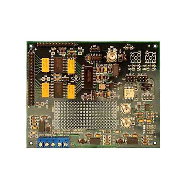
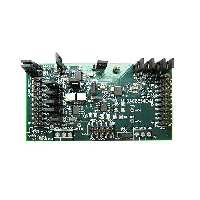
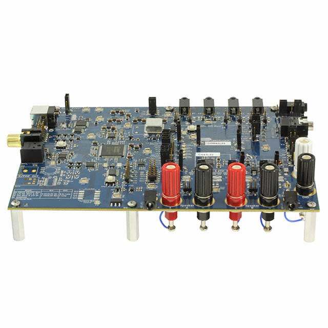
ICGOO电子元器件商城为您提供DAC5687EVM由Texas Instruments设计生产,在icgoo商城现货销售,并且可以通过原厂、代理商等渠道进行代购。 DAC5687EVM价格参考。Texas InstrumentsDAC5687EVM封装/规格:评估板 - 数模转换器 (DAC), DAC5687 16 Bit 500M Samples Per Second Digital to Analog Converter (DAC) Evaluation Board。您可以下载DAC5687EVM参考资料、Datasheet数据手册功能说明书,资料中有DAC5687EVM 详细功能的应用电路图电压和使用方法及教程。
Texas Instruments(德州仪器)的DAC5687EVM是一款用于评估DAC5687数模转换器性能的开发板。该评估板主要应用于需要高性能、高精度信号生成的场景,以下是其典型应用场景:

1. 通信系统:DAC5687EVM适用于无线通信基站、软件定义无线电(SDR)和调制解调器等设备中,用于生成高质量的射频(RF)或中频(IF)信号。其16位分辨率和高达200 MSPS的采样率使其能够满足现代通信系统对带宽和动态范围的需求。

2. 测试与测量设备:在示波器、信号发生器和其他精密测量仪器中,DAC5687EVM可用于生成精确的模拟波形,支持复杂的测试环境和校准需求。

3. 医疗成像与诊断:该评估板适合用于超声设备、核磁共振(MRI)和其他医学成像系统,提供高精度的信号生成能力,以确保图像质量和诊断准确性。

4. 工业自动化与控制:在工业领域,DAC5687EVM可以用于可编程逻辑控制器(PLC)、伺服驱动器和数据采集系统中,实现对模拟信号的精确控制和输出。

5. 音频处理:对于专业音频设备,如数字混音台或音频接口,DAC5687EVM能够生成低失真、高保真的音频信号,满足高端音频应用的需求。

6. 雷达与传感器融合:在雷达系统和传感器融合应用中,DAC5687EVM可用于生成复杂的波形信号,支持目标检测和跟踪功能。

通过使用DAC5687EVM,工程师可以快速验证DAC5687的功能特性,并优化设计参数,从而加速产品开发周期。此外,该评估板还提供了灵活的接口选项和配置工具,便于用户根据具体应用场景进行定制化设置。
| 参数 | 数值 |
| 产品目录 | 编程器,开发系统嵌入式解决方案 |
| DAC数 | 2 |
| DAC类型 | 电流 |
| 描述 | EVALUATION MODULE FOR DAC5687数据转换 IC 开发工具 DAC5687 Eval Mod |
| 产品分类 | 评估板 - 数模转换器 (DAC)工程工具 |
| 品牌 | Texas Instruments |
| 产品手册 | |
| 产品图片 |
|
| rohs | 否含铅 / 不符合限制有害物质指令(RoHS)规范要求 |
| 产品系列 | 模拟与数字IC开发工具,数据转换 IC 开发工具,Texas Instruments DAC5687EVM- |
| 数据手册 | 点击此处下载产品Datasheethttp://www.ti.com/lit/pdf/slwu017 |
| 产品型号 | DAC5687EVM |
| 产品 | Evaluation Boards |
| 产品培训模块 | http://www.digikey.cn/PTM/IndividualPTM.page?site=cn&lang=zhs&ptm=13240 |
| 产品目录页面 | |
| 产品种类 | 数据转换 IC 开发工具 |
| 位数 | 16 |
| 使用的IC/零件 | DAC5687 |
| 其它名称 | 296-18682 |
| 制造商产品页 | http://www.ti.com/general/docs/suppproductinfo.tsp?distId=10&orderablePartNumber=DAC5687EVM |
| 商标 | Texas Instruments |
| 工作温度 | -40°C ~ 85°C |
| 工作电源电压 | 1.8 V to 3.3 V |
| 工具用于评估 | DAC5687 |
| 工厂包装数量 | 1 |
| 建立时间 | 10.4ns |
| 所含物品 | 板 |
| 接口类型 | SMA |
| 数据接口 | 并联 |
| 标准包装 | 1 |
| 相关产品 | /product-detail/zh/DAC5687IPZP/296-17935-ND/765296/product-detail/zh/DAC5687IPZPG4/DAC5687IPZPG4-ND/1509032/product-detail/zh/DAC5687IPZPR/DAC5687IPZPR-ND/1509033 |
| 类型 | DAC |
| 采样率(每秒) | 500M |


- 商务部:美国ITC正式对集成电路等产品启动337调查
- 曝三星4nm工艺存在良率问题 高通将骁龙8 Gen1或转产台积电
- 太阳诱电将投资9.5亿元在常州建新厂生产MLCC 预计2023年完工
- 英特尔发布欧洲新工厂建设计划 深化IDM 2.0 战略
- 台积电先进制程称霸业界 有大客户加持明年业绩稳了
- 达到5530亿美元!SIA预计今年全球半导体销售额将创下新高
- 英特尔拟将自动驾驶子公司Mobileye上市 估值或超500亿美元
- 三星加码芯片和SET,合并消费电子和移动部门,撤换高东真等 CEO
- 三星电子宣布重大人事变动 还合并消费电子和移动部门
- 海关总署:前11个月进口集成电路产品价值2.52万亿元 增长14.8%

PDF Datasheet 数据手册内容提取
DAC5687 EVM User's Guide LiteratureNumber:SLWU017C APRIL2005–RevisedAugust2013
Contents 1 Overview ............................................................................................................................ 4 1.1 Purpose ................................................................................................................... 4 1.2 EVMBasicFunctions ................................................................................................... 4 1.3 PowerRequirements.................................................................................................... 4 1.4 SoftwareInstallation..................................................................................................... 5 1.5 HardwareConfiguration ................................................................................................ 5 2 DAC5687EVMOperationalProcedure ................................................................................... 6 2.1 StartingtheSerialInterfaceProgram ................................................................................. 9 2.2 DAC5687InitialSetupTests ......................................................................................... 10 2.3 BasicTestProcedurewithTSW1400 ............................................................................... 12 2.4 DAC5687GUIRegisterDescriptions ............................................................................... 18 3 PhysicalDescription .......................................................................................................... 20 3.1 PCBLayout ............................................................................................................. 20 3.2 PartsList ................................................................................................................ 24 4 CircuitDescription ............................................................................................................. 26 4.1 InputClocks ............................................................................................................ 26 4.2 InputData ............................................................................................................... 26 4.3 OutputData ............................................................................................................. 27 4.4 ControlInputs .......................................................................................................... 28 4.5 InternalReferenceOperation ........................................................................................ 28 4.6 ExternalReferenceOperation........................................................................................ 28 5 Schematics ....................................................................................................................... 29 RevisionAHistory ...................................................................................................................... 30 RevisionBHistory ...................................................................................................................... 30 RevisionCHistory ...................................................................................................................... 30 2 TableofContents SLWU017C–APRIL2005–RevisedAugust2013 SubmitDocumentationFeedback Copyright©2005–2013,TexasInstrumentsIncorporated
www.ti.com List of Figures 1 SerialInterfaceGUI......................................................................................................... 9 2 DAC5687SetupforX4LModeandNCOToneatF /25........................................................... 10 DAC 3 SpectrumwithCLK2=500MHz,X4LInterpolationandNCOFrequency=343597383........................ 11 4 DAC5687SetupforX4ModeandNCOToneatF /15............................................................ 12 DAC 5 ConnectingTSW1400andDAC5687Together....................................................................... 13 6 ClocksSynchronisationBetweenDAC5687andTSW1400......................................................... 14 7 DAC5687GUISetup...................................................................................................... 15 8 SelectCMOSinHSDCPRO............................................................................................. 15 9 LoadDACFirmwarePrompt............................................................................................. 16 10 HSDCProSetupforOneToneGeneration ........................................................................... 16 11 1ToneTest,noNCO..................................................................................................... 17 12 NCOConfiguration........................................................................................................ 17 13 1ToneTest,NCOActivated,IF=20Mhz.............................................................................. 18 14 TopLayer1 ................................................................................................................ 21 15 Layer2,GroundPlane.................................................................................................... 22 16 Layer3,PowerPlane..................................................................................................... 23 17 BottomLayer............................................................................................................... 24 List of Tables 1 DAC5687EVMPartsList ................................................................................................ 25 2 InputConnectorJ13(DataABus) ..................................................................................... 26 3 InputConnectorJ14(DataBBus) ..................................................................................... 27 4 TransformerOutputConfiguration....................................................................................... 27 SLWU017C–APRIL2005–RevisedAugust2013 ListofFigures 3 SubmitDocumentationFeedback Copyright©2005–2013,TexasInstrumentsIncorporated
User's Guide SLWU017C–APRIL2005–RevisedAugust2013 DAC5687 EVM 1 Overview Thisuser'sguidedocumentgivesageneraloverviewoftheDAC5687evaluationmodule(EVM)and providesageneraldescriptionofthefeaturesandfunctionstobeconsideredwhileusingthismodule. 1.1 Purpose TheDAC5687EVMprovidesaplatformforevaluatingtheDAC5687digital-to-analogconverter(DAC) undervarioussignal,reference,andsupplyconditions.Thisdocumentshouldbeusedincombinationwith theEVMschematicdiagramsupplied. 1.2 EVM Basic Functions DigitalinputstotheDACcanbeprovidedwithCMOSlevelsignalsupto250MSPS(externalclockmode) throughtwo34-pinheaders.Thisenablestheusertoprovidehigh-speeddigitaldatatotheDAC5687 device. TheanalogoutputsfromtheDACareavailableviaSMAconnectors.Becauseofitsflexibledesignthe analogoutputsoftheDAC5687devicecanbeconfiguredtodrivea50-Ω terminatedcableusinga4:1or 1:1impedanceratiotransformer,orsingle-endedreferredtoAVDD.TheEVMalsoallowsforanoptionto doubletheoutputpowerbysummingtheDACAandDACBoutputsthrougha1:1transformer. TheEVMallowstheusertoinputsingle-ended,TTL/CMOSlevelsignals,togeneratedifferentialclock sourcesforbothCLK1andCLK2.SeeSection4.1,InputClocks,forproperconfigurationandoperation. PowerconnectionstotheEVMareviabananajacksockets. InadditiontotheinternalbandgapreferenceprovidedbytheDAC5687device,optionsontheEVMallow anexternalreferencetobeprovidedtotheDAC. TheDAC5687EVMallowstheusertoprogramtheDAC5687internalregisterswiththesuppliedcomputer parallelportcableandserialinterfacesoftware.Theinterfaceallowsreadandwriteaccesstoallregisters thatdefinetheoperationmodeoftheDAC5687device. 1.3 Power Requirements Thedemonstrationboardrequiresonlytwopowersupplies.3.3VdcisrequiredatbananajackJ7,withthe returnconnectedtoJ9.1.8VdcisrequiredatbananajackJ8,withthereturntoJ10. 1.3.1 VoltageLimits CAUTION Exceeding the maximum input voltages can damage EVM components. Undervoltage may cause improper operation of some or all of the EVM components. 4 DAC5687EVM SLWU017C–APRIL2005–RevisedAugust2013 SubmitDocumentationFeedback Copyright©2005–2013,TexasInstrumentsIncorporated
www.ti.com Overview 1.4 Software Installation AllnecessarysoftwaretooperatetheserialinterfaceisprovidedontheenclosedCD-ROM. 1. InserttheCD-ROMintothecomputertobeusedtooperatetheserialinterface. 2. ClickonthezippeddirectorycalledDAC5687SPI_Installv2p2.zip.Extractallofthefilesintoanew directory,calledC:\temp,onthePC. 3. Gothefollowingdirectory:C:\temp\Installer.Doubleclickonthefilecalled setup.exe. 4. Thesoftwarewillcreateatopleveldirectoryatthefollowinglocation: C:\Program Files\TI.fdr\DAC5687_SPI.Thisdirectorywillcontaintherequiredfilesaswellasalabwindows-cvi runtimeenginetorunthesoftware. 5. Oncetheinstallationiscomplete,thesoftwareislaunchedbyrunning DAC5687_SPI.exe.See Chapter2,DAC5687EVMOperationalProcedure,forinstructionsonoperatingtheserialinterface software. 1.5 Hardware Configuration TheDAC5687EVMcanbesetupinavarietyofconfigurationstoaccommodateaspecificmodeof operation.Beforestartingevaluation,theusershoulddecideontheconfigurationandmakethe appropriateconnectionsorchanges.Thedemonstrationboardcomeswiththefollowingfactory-set configuration: • DifferentialclockmodeusingtransformersT3andT4.Inputsingle-endedclocksarerequiredatJ3and J4. • Transformer-coupledoutputsusing4:1transformersT1andT2. • Theconverterissettooperatewithinternalreference.JumperW1isinstalledbetweenpins2and3. • Full-scaleoutputcurrentsetto20mAthroughRBIASresistorR1. • TheDAC5687outputisenabled(sleepmodedisabled). • TxENABLEissethightoenabletheDAC5687devicetoprocessdata.Ajumperisinstalledbetween pins11and12onJ15. • InternalPLLdisabled.JumperW3isinstalledbetweenpins2and3. • Inputdatalevelissetto+3.3VDC.JumperW2isinstalledbetweenpins1and2. TopreparetheDAC5687EVMforevaluation,connectthefollowing: 1. 3.3VtoJ7andthereturntoJ9. 2. 1.8VtoJ8andthereturntoJ10. 3. Provideasingle-ended,1-V ,0-Voffsetsine-wavesignaltoSMAconnectorJ3(CLK1)iftheinternal PP PLListobeused.ConnectthissignaltoSMAconnectorJ4(CLK2)ifthePLLisdisabled.Asecond sine-wavesourceisrequiredonlyfordualclockmode.Inthismode,thesignalonCLK1isusedto clockdataintotheDAC5687andthesignalonCLK2isusedtoclocktheinternalDAC.CLK1and CLK2mustbephase-alignedforthisoptiontoworkproperly.Inordertopreservethespecified performanceoftheDAC5687converter,theclocksourcesmustfeatureverylowjitter.Usingaclock witha50%dutycyclegivesoptimumdynamicperformance. 4. Useadigitaltestpatterngeneratorwith50-Ω outputstoprovide3.3-VCMOSlogiclevelinputsto connectorsJ13andJ14.Adjustthedigitalinputstoprovidethepropervoltagelevelsandsetupand holdtimesattheDAC5687inputs.SeetheDAC5687datasheet(SLWS164)fortiminginformation. AnothersolutionistousetheTSW1400patterngeneratorcardasexplainedinSection2.3 5. ConnectoneendofthesuppliedserialinterfacecabletotheparallelportofaPC.Connecttheother endofthecabletoJ1ontheEVM.TheusercanalsousetheprovidedUSBtoSPIadapter,setupis explainedinSection2. 6. TheDAC5687outputscanbemonitoredusingSMAconnectorJ5forIOUTAandSMAconnectorJ19 forIOUTB. SLWU017C–APRIL2005–RevisedAugust2013 DAC5687EVM 5 SubmitDocumentationFeedback Copyright©2005–2013,TexasInstrumentsIncorporated
DAC5687EVMOperationalProcedure www.ti.com 2 DAC5687 EVM Operational Procedure TopreparetheDAC5687EVMforoperation,followthesesteps: 1. ParallelPortInterface:Connectoneendofthesuppliedserialinterfacecabletotheparallelportofa PCandtheotherendofthecabletoJ1ontheEVMandskipsteps2to7. 2. USBInterface: ConnecttheprovidedUSBtoSPIadapterboardtotheparallelportconnectoronthe EVMandtoaspareUSBportonthehostPCusingthesuppliedUSBcable.TheWindowsFoundNew HardwareWizardshouldopen;ifthisisnotthecasemakesurethecableisconnectedproperly.Select “No,notthistime”fromtheoptionsavailableandthenclick “Next”toproceedwiththeinstallation. 6 DAC5687EVM SLWU017C–APRIL2005–RevisedAugust2013 SubmitDocumentationFeedback Copyright©2005–2013,TexasInstrumentsIncorporated
www.ti.com DAC5687EVMOperationalProcedure 3. Select"Installthesoftwareautomatically(recommended)"asshownbelowandthenclick"Next". 4. IfWindowsisnotabletofindtheappropriateUSBdriverspress “Back”andselect “Installfromalistor specificlocation(advanced)”.Click“Next”. 5. Select"Searchforthebestdriverintheselocations"andbrowseforthefolderwheretheDAC5687 programwasinstalled(thedefaultlocationisC:\ProgramFiles\TexasInstruments\DAC5687).Oncethe filepathhasbeenselected,click“Next”toproceed. SLWU017C–APRIL2005–RevisedAugust2013 DAC5687EVM 7 SubmitDocumentationFeedback Copyright©2005–2013,TexasInstrumentsIncorporated
DAC5687EVMOperationalProcedure www.ti.com 6. IfWindowsXPisconfiguredtowarnwhenunsigned(non-WHQLcertified)driversareabouttobe installed,thefollowingscreenisdisplayedunlessinstallingaMicrosoftWHQLcertifieddriver.Clickon "ContinueAnyway"tocontinuewiththeinstallation.IfWindowsXPisconfiguredtoignorefile signaturewarnings,nomessagewillappear. 7. Windowsshouldthendisplayamessageindicatingthattheinstallationwassuccessful.Click"Finish" tocompletetheinstallation. 8 DAC5687EVM SLWU017C–APRIL2005–RevisedAugust2013 SubmitDocumentationFeedback Copyright©2005–2013,TexasInstrumentsIncorporated
www.ti.com DAC5687EVMOperationalProcedure 2.1 Starting the Serial Interface Program PoweruptheEVM.Afterpowerup,depressswitchS1toresettheDAC5687.Startthesoftwareby runningthefollowingexecutable: C:\ProgramFiles\TI.fdr\DAC5687_SPI\DAC5687_SPI.exe. IftheEVMispoweredonwiththeparallelportconnectedproperly,thentheGUIshowninFigure1 is displayedwiththedefaultsettingsreadfromthedevice.IfusingtheUSBinterfacecard,changemodeto USBintheupperrightcornerwindow.Thehardwareandsoftwarearenowreadyfortesting.Forserial interfaceoperation,simplyclickontheswitches,up/downarrows,etc.,toselectthedesiredsettingsofthe DAC5687.Ifthereisaproblemwiththecommunication,suchastheEVMisnotpoweredonorthe parallelportcableisnotconnected,anerrormessagewillbedisplayedinstructingtheusertocorrectthe problem.Oncecorrected,hitthe"ReadAll"button,locatedinthelowerrightcorneroftheGUI,toreadthe defaultsettingsofthedevice. Figure1.SerialInterfaceGUI Fornormaloperation,theuserneedsonlytoselectvaluesandswitchesasdesired.Thevaluesare automaticallysenttothedeviceandreadbacktoverifytheirconfiguration. SLWU017C–APRIL2005–RevisedAugust2013 DAC5687EVM 9 SubmitDocumentationFeedback Copyright©2005–2013,TexasInstrumentsIncorporated
DAC5687EVMOperationalProcedure www.ti.com 2.2 DAC5687 Initial Setup Tests ThereareseveralinitialtestswiththeDAC5687thatcanbedonewithoutanyinputdata.Thefollowing setupstepsaresuggestedtofamiliarizetheuserwiththeDAC5687andEVMsoftwareandverifythatthe DAC5687isfunctioningproperly. 1. ProvideaCLK2inputifthePLLisdisabledoraCLK1inputifthePLLisenabled(W3).Donotprovide parallelinputdata. 2. PowerupEVMwith1.8VDVDDand3.3VAVDD 3. StartDAC5687_SPIsoftware. 4. Clickonthe"LoadRegs"buttonontheGUI.Anewdirectorywindowwillopen.Clickonthefilecalled "UserGuideTest.reg5687".Clickon"OK".ThiswillloadatestsettingfortheDAC,correspondingto F /12.5=20MHzforCLK2=500MSPS(F =F /2forX4Lmode).TheGUIshouldnowlookas NCO NCO DAC showninFigure2. Figure2.DAC5687SetupforX4LModeandNCOToneatF /25 DAC 10 DAC5687EVM SLWU017C–APRIL2005–RevisedAugust2013 SubmitDocumentationFeedback Copyright©2005–2013,TexasInstrumentsIncorporated
www.ti.com DAC5687EVMOperationalProcedure ThistoneisbeinggeneratedbytheDAC5687NCO.WithnoinputdataprovidedtoconnectorsJ13 andJ14,theChannelAandBdatabusinputswillallbezeros,orafullscalenegativevalueinthe defaultoffsetbinaryformat.IntheX4Lmode,afterthefirst2xinterpolation,thefullscaleDCinput signalataclockrateof250MSPSismixedwiththeNCOrunningatthesettingofF /12.5 NCO (343597383)togenerateatoneat20MHz.Afterasecond2xinterpolation,a20MHztoneisoutput fromtheDACsamplingat500MSPS.TheoutputspectrumshouldbesimilartoFigure3. Figure3.SpectrumwithCLK2=500MHz,X4LInterpolationandNCOFrequency=343597383 5. ChangetheModeto1000F /4(+,+),correspondingtoF /4(seedatasheet).Thiswillincreasethe DAC DAC outputbyF /4to20MHz+125MHz=145MHz. DAC 6. ChangingtheNCODDSto3951369913(232x(1-20/250))willnowresultinanoutputtoneat125MHz -20MHz=105MHz. 7. ChangetheinterpolationtoX4,andthemodeto NoMixing,theNCODDCto286331153(F /15)and NCO reducetheCLK2frequencyto <320MSPS.TheGUIshouldlookasshowninFigure4.TheNCOis nowrunningattheDACupdaterate(=CLK2).ForCLK2=300MSPS,theresultisanoutputtoneat 20MHz. SLWU017C–APRIL2005–RevisedAugust2013 DAC5687EVM 11 SubmitDocumentationFeedback Copyright©2005–2013,TexasInstrumentsIncorporated
DAC5687EVMOperationalProcedure www.ti.com Figure4.DAC5687SetupforX4ModeandNCOToneatF /15 DAC 2.3 Basic Test Procedure with TSW1400 ThissectionoutlinesthebasictestprocedurefortestingtheEVMwiththeTSW1400. 2.3.1 TSW1400Overview TheTSW1400isahighspeeddatacaptureandpatterngeneratorboard.Formoredetailedexplanationof theTSW1400setupandoperation,seetheTSW1400user’sguide(SLWU079).Thisdocumentassumes thattheHighSpeedDataConverterProsoftware(availabletodownloadhere: http://www.ti.com/tool/tsw1400evm)isinstalledandfunctioningproperly. 12 DAC5687EVM SLWU017C–APRIL2005–RevisedAugust2013 SubmitDocumentationFeedback Copyright©2005–2013,TexasInstrumentsIncorporated
www.ti.com DAC5687EVMOperationalProcedure 2.3.2 TestBlockDiagramsforTSW1400 AsdescribedinFigure5,thefirststepsconsistinconnectingboardstogetherthroughCMOSinterface, connectingUSBinterfacestoaPCandconnectingasourceclocktoCLK2andoneoutputtoasignal analyzer. Figure5.ConnectingTSW1400andDAC5687Together Next,asshowninFigure6,itisimportanttoconnectthePLLoutputoftheDAC5687 “PLLLOCKout” to the “CMOSCLK” inputoftheTSW1400inordertosynchronizethedatarates.Finally,supplythe DAC5687with1.8Vand3.3V,andsupplyingtheTSWwitha5Vjack. SLWU017C–APRIL2005–RevisedAugust2013 DAC5687EVM 13 SubmitDocumentationFeedback Copyright©2005–2013,TexasInstrumentsIncorporated
DAC5687EVMOperationalProcedure www.ti.com Figure6.ClocksSynchronisationBetweenDAC5687andTSW1400 2.3.3 DAC5687ExampleSetupProcedure LaunchtheDAC5687GUIandcheckforvalidconnectionforeitherparallelorUSBconnection.Press resetbuttonontheDAC5687EVMandpress"ReadAll"buttonontheGUItoupdatetheDAC5687reset valuetotheGUI. Forthisfirsttest,disableNCOandleavetherestasdefault. NOTE: OneimportantdetailistomakesuretoenableRevBbussincechannelBisB(15:0)whenA isA(0:15)onRev.BoftheEVM. TheBusBisreversedtoavoiddatalinescrossingonthelayout,seeSection4.2 fordetails. ThesetupshouldlooklikeFigure7. 14 DAC5687EVM SLWU017C–APRIL2005–RevisedAugust2013 SubmitDocumentationFeedback Copyright©2005–2013,TexasInstrumentsIncorporated
www.ti.com DAC5687EVMOperationalProcedure Figure7. DAC5687GUISetup 2.3.4 TSW1400ExampleSetupProcedure AsingletonewithHSDCproisgeneratedinthissection. 1. StarttheHighSpeedConverterProGUIprogram.Whentheprogramstarts,selecttheDACtaband thenselectCMOSfirmwareinthe“SelectDAC”menu. Figure8.SelectCMOSinHSDCPRO SLWU017C–APRIL2005–RevisedAugust2013 DAC5687EVM 15 SubmitDocumentationFeedback Copyright©2005–2013,TexasInstrumentsIncorporated
DAC5687EVMOperationalProcedure www.ti.com 2. Whenprompted‘loadDACfirmware?’,selectYES. Figure9.LoadDACFirmwarePrompt Inthistest,a122.88MHzDACclockisusedwith2xinterpolation,soDatarateis61.44MHz. 3. Select61.44MhzDatarate,Offsetbin 4. Generateaonetonetest,herea5MHzcomplex ResultshouldlooklikeFigure10. Figure10.HSDCProSetupforOneToneGeneration Sendthegeneratedsignalclickingonsend.RemoveandputtheTXenablejumpertosynchronizethe FIFO. ResultonthesignalanalyzershouldbesimilartoFigure11. 16 DAC5687EVM SLWU017C–APRIL2005–RevisedAugust2013 SubmitDocumentationFeedback Copyright©2005–2013,TexasInstrumentsIncorporated
www.ti.com DAC5687EVMOperationalProcedure Figure11.1ToneTest,noNCO NextstepcanbetoactivatetheNCO.Todoso: 1. SwitchontheNCOfeatureontheDAC5687GUI. 2. SetF to122.88MhzandNCOIFto20MHzforinstance DAC 3. Clickonupdate,itwillautomaticallycalculatetheNCODDsvalueandsendit ResultofthesetupisshowninFigure12. Figure12. NCOConfiguration ResultonthesignalanalyzerisshowninFigure13. SLWU017C–APRIL2005–RevisedAugust2013 DAC5687EVM 17 SubmitDocumentationFeedback Copyright©2005–2013,TexasInstrumentsIncorporated
DAC5687EVMOperationalProcedure www.ti.com Figure13.1ToneTest,NCOActivated,IF=20Mhz 2.4 DAC5687 GUI Register Descriptions 2.4.1 RegisterControls ⋅ LoadRegs: LoadsregistervaluesfromasavedfiletotheDAC5687andupdatestheGUI. ⋅ SaveRegs: SavescurrentGUIregisterssettingstoatextfileforfutureuse. ⋅ ReadAll: ReadsthecurrentregistersoftheDAC5687.Thisisusedtoverifysettingsonthefrontpanel. ⋅ SendAll: Sendsthecurrentfrontpanelregisterstothedevice.ThisisgenerallyonlyusedwhentheEVM powerhasrecycledorthedevicehasbeenresetandtheuserwantstoloadthedisplayedsettings tothedevice. 2.4.2 ConfigurationControls ⋅ FullBypass: Whenset,allfiltering,QMC,andNCOfunctionsarebypassed. ⋅ FIRBypass: Whenset,theinterpolationfiltersarebypassed. ⋅ FIFOBypass: Whensettobypass,theinternal4sampleFIFOisdisabled.Whencleared,theFIFOisenabled. ⋅ FIRA: AsidefirstFIRfilterinhighpassmodewhenset,lowpassmodewhencleared. ⋅ FIRB: BsidefirstFIRfilterinhighpassmodewhenset,lowpassmodewhencleared. ⋅ DualClk: OnlyusedwhenthePLLisdisabled.Whenset,twodifferentialclocksareusedtoinputthedatato thechip;CLK1/CLK1Cisusedtolatchtheinputdataintothechip,andCLK2/CLK2Cisusedasthe DACsampleclock 18 DAC5687EVM SLWU017C–APRIL2005–RevisedAugust2013 SubmitDocumentationFeedback Copyright©2005–2013,TexasInstrumentsIncorporated
www.ti.com DAC5687EVMOperationalProcedure ⋅ Interleave: Whenset,interleavedinputdatamodeisenabled;bothAandBdatastreamsareinputatthe DA(15:0)inputpins. ⋅ InverseSinc: Enablesinversesincfilter. ⋅ HalfRateInput: Enableshalfrateinputmode.InputdatafortheDACAdatapathisinputtothechipathalfspeed usingboththeDA(15:0)andDB(15:0)inputpins. ⋅ Sif: Setssif_4pinbit.4pinserialinterfacemodeisenabledwhenon,3pinmodewhenoff.The DAC5687EVMisconfiguredfora3pinserialinterface.The4bitserialinterfacewillnotworkwith theDAC5687EVM. ⋅ Inv.PLLLock: OnlyusedwhenPLLisdisabledanddualclockmodeisdisabled.Whencleared,inputdatais latchedintothechipontherisingedgeofthePLLLOCKoutputpin.Whenset,inputdataislatched intothechiponthefallingedgeofthePLLLOCKoutputpin. ⋅ PLLFreq: SetsPLLVCOcenterfrequencytoloworhighcenterfrequency. ⋅ PLLKv: SetsPLLVCOgaintoeitherhighorlowgain. ⋅ Qflag: Setsqflagbit.Whenset,theQFLAGinputpinoperatesasaBsampleindicatorwheninterleaved dataisenabled.Whencleared,theTXENABLErisingdeterminestheA/Btimingrelationship. ⋅ 2'sComp: Whenset,inputdataisinterpretedas2'scomplement.Whencleared,inputdataisinterpretedas offsetbinary. ⋅ RevABus: Whencleared,ChannelAinputdataMSBtoLSBorderisDA(15)=MSBandDA(0)=LSB.When set,ChannelAinputdataMSBtoLSBorderisreversed,DA(15)=LSBandDA(0)=MSB. ⋅ RevBBus: Whencleared,ChannelBinputdataMSBtoLSBorderisDB(15)=MSBandDB(0)=LSB.When set,ChannelBinputdataMSBtoLSBorderisreversed,DB(15)=LSBandDB(0)=MSB. ⋅ USB: Whenset,thedatatoDACBisinvertedtogenerateuppersidebandoutput. ⋅ Inv.ClkI(Q): InvertstheDACcoresampleclockwhenset,normalwhencleared. ⋅ Sync_Phstr: Whenset,theinternalclockdividerlogicisinitializedwithaPHSTRpinlowtohightransition. ⋅ Sync_cm: Whenset,thecoarsemixerissynchronizedwithaPHSTRlowtohightransition. ⋅ Sync_NCO: Whenset,theNCOphaseaccumulatorisclearedwithaphstrlowtohightransition. ⋅ PhstrClkDiv SelectstheclockusedtolatchthePHSTRinputwhenrestartingtheinternalclockdividers.When Select: set,thefullrateCLK2signallatchesPHSTR.Whencleared,thedivideddowninputclocksignal latchesPHSTR. ⋅ DACSerialData: Whenset,bothDACAandDACBinputdataisreplacedwithfixeddataloadedintothe16bit serialinterfaceDACStaticData. o CounterMode:ControlstheinternalcounterthatcanbeusedastheDACdatasource.Seethe datasheetformoreinformation. o DACStaticData:WhenDACSerialDataisset,bothDACAandDACBinputdataisreplaced withfixeddataloadedwiththisvalue.Range=0to65535. ⋅ NCO: Whenset,enablesNCO. o NCOGain:SetsNCOgainresultingina2xincreaseinNCOoutputamplitude.ExceptforF /2and S F /4mixingNCOfrequencies,thisselectioncanresultinsaturationforfullscaleinputs.Consider S usingQMCgainforlowergains. ⋅ QMC: Whenset,enablestheQMC. o QMCAGain:SetsQMCgainAtoarange=0to2047.Seethedatasheetformoreinformation. o QMCBGain:SetsQMCgainBtoarange=0to2047.Seethedatasheetformoreinformation. o QMCPhase:SetsQMCphasetoarange=-512to511.Seethedatasheetformoreinformation. ⋅ Mode: Usedtoselectthecoarsemixermode.SeetheDAC5687datasheetformoreinformation. ⋅ PLLDivider: SetsVCOdividertodivby1,2,4,or8. ⋅ Interpolation: SetsFIRInterpolationfactor:{X2,X4,X4L,X8}.X4useslowerpowerthan4xL,butF =320 DAC MSPSmaxwhenNCOorQMCareused. ⋅ PhstrInit.Phase: AdjuststheinitialphaseoftheF /2andF /4cmixblockatPHSTR. S S ⋅ SyncFIFO: SyncsourceselectionmodefortheFIFO.Whenalowtohightransitionisdetectedontheselected syncsource,theFIFOinputandoutputpointersareinitialized.SeetheDAC5687datasheetfor sourcedescription. ⋅ Alt.PLLLOCK SetsPLLLOCKoutputpintoF frequencywhenoperatinginthePLLmode.Settingsmustbe DAC Output: usedinconjunctionwiththeinterpolationsettingtoachieveddesiredrate(i.e.settoF /2for2x DAC interpolation,settoF /4for4xinterpolation).Note,thereisnooptionforthe8xmode.The DAC jumperatW1(EXTLO)mustberemovedtoutilizethisfunctionality. SLWU017C–APRIL2005–RevisedAugust2013 DAC5687EVM 19 SubmitDocumentationFeedback Copyright©2005–2013,TexasInstrumentsIncorporated
PhysicalDescription www.ti.com 2.4.3 DACA(B)Gain ⋅ DACCoarse SetscoarsegainofDACA(B)fullscalecurrent.Rangeis0to15.SeetheDAC5687datasheetfor Gain: fullscalegainequation. ⋅ DACFineGain: SetsfinegainofDACA(B)fullscalecurrent.Rangeis-128to127.SeetheDAC5687datasheetfor fullscalegainequation. ⋅ DACDCOffset: SetsDACA(B)DCoffsetregister.Rangeis-4096to4095. ⋅ Sleep: DACA(B)sleepswhenset,operationalwhencleared. 2.4.4 NCO ⋅ NCODDS: SetsNCODDSregisters.SeetheDAC5687datasheetforformula. ⋅ NCOPhase: SetsinitialNCOphaseregisters.SeetheDAC5687datasheetformoreinformation. FDac: SettheDACfrequencyinMhzforNCODDScalculation NCOIF: SetIFinMhzforNCODDScalculation 2.4.5 AdditionalControl/MonitorRegisters ⋅ PllPortConfig: Selectionofthisbuttonwillbringupaseparatewindowthatshowstheparallelportconfigurationof thesoftware.TheEVMMenushouldbeloadedwithDACEVM.Thisbuttonalsoallowstheuserto changetheLPTaddressusedbythePC.Thisissetbyenteringavalidaddressinsidethebox labeled"LPTAddress".Thedefaultsettingis378. ⋅ Quit: QuitstheoperationoftheDAC5687software. ⋅ Version: Displaystheversionofthesilicon.Ifaversionof0isreadthenthecommunicationisnotfunctioning andanerrormessagewillbedisplayed. ⋅ About: Opensanadditionalwindowwithhelprelatedtopicsforthesoftware. 3 Physical Description ThischapterdescribesthephysicalcharacteristicsandPCBlayoutoftheEVMandliststhecomponents usedonthemodule. 3.1 PCB Layout TheEVMisconstructedona4-layer,4.9-inchx6.5-inch,0.055-inchthickPCBusingFR-4material. Figure14throughFigure17 showthePCBlayoutfortheEVM. 20 DAC5687EVM SLWU017C–APRIL2005–RevisedAugust2013 SubmitDocumentationFeedback Copyright©2005–2013,TexasInstrumentsIncorporated
www.ti.com PhysicalDescription Figure14.TopLayer1 SLWU017C–APRIL2005–RevisedAugust2013 DAC5687EVM 21 SubmitDocumentationFeedback Copyright©2005–2013,TexasInstrumentsIncorporated
PhysicalDescription www.ti.com Figure15.Layer2,GroundPlane 22 DAC5687EVM SLWU017C–APRIL2005–RevisedAugust2013 SubmitDocumentationFeedback Copyright©2005–2013,TexasInstrumentsIncorporated
www.ti.com PhysicalDescription Figure16.Layer3,PowerPlane SLWU017C–APRIL2005–RevisedAugust2013 DAC5687EVM 23 SubmitDocumentationFeedback Copyright©2005–2013,TexasInstrumentsIncorporated
PhysicalDescription www.ti.com Figure17.BottomLayer 3.2 Parts List Table1liststhepartsusedinconstructingtheEVM. 24 DAC5687EVM SLWU017C–APRIL2005–RevisedAugust2013 SubmitDocumentationFeedback Copyright©2005–2013,TexasInstrumentsIncorporated
www.ti.com PhysicalDescription Table1.DAC5687EVMPartsList BillofMaterialForDAC5687 Value Qty. PartNumber Vendor RefDes NotInstalled CAPACITORS 47uF,tantalum,10%,10V 6 10TPA47M Sanyo C53-C58 10uF,10V,10%capacitor 12 GRM42X5R106K10 Murata C24,C26-C28,C30-C32, C35,C37-C39,C41 1uF,16V,10%capacitor 6 ECJ-3YB1C105K Panasonic C36,C42-C46 0.1uF,16V,10%capacitor 3 ECJ-2VB1C104K Panasonic C21,C22,C23 0.01uF,50V,5%capacitor 6 ECJ-2VB1H103K Panasonic C47-C52 0.01uF,16V,10%capacitor 2 ECJ-1VB1C103K Panasonic C19,C20 0.1uF,16V,10%capacitor 4 ECJ-1VB1C104K Panasonic C25,C40,C60,C61 0.1uF,16V,+80/-20%capacitor 21 ECJ-0EF1C104Z Panasonic C1C2C4-C13,C15-C18, C29,C59,C84-C86 0.01uF,25V,10%capacitor 1 ECJ-0EF1E103Z Panasonic C14 0.033uF,25V,+80/-20% 1 ECU-E1C333ZFQ Panasonic C34 capacitor 10pF,50V,5%capacitor 1 ECU-E1H100DCQ Panasonic C3 330pF,50V,5%capacitor 1 ECU-V1H331JCV Panasonic C33 RESISTORS 10-kΩresistor1/16W,1% 4 ERJ-6ENF1002V Panasonic R34-R37 10-Ωresistor1/16W,1% 1 ERJ-6ENF10R0V Panasonic R3 R15 10-Ωresistor1/16W,1% 1 ERJ-2RFK10R0X Panasonic R43 0-Ωresistor,1/16W,1% 4 ERJ-3GEY0R00V Panasonic R23,R26,R38,R42 R6-R9,R24,R27-R33 49.9-Ωresistor,1/16W,1% 3 ERJ-3EKF49R9V Panasonic R12,R13,R39 R40 110-Ωresistor,1/10W,1% 0 ERA-3EKF110V Panasonic R18 200-Ωresistor,1/16W,1% 2 ERJ-3EKF200V Panasonic R11,R14 93.1-Ωresistor,1/16W,1% 1 ERJ-3EKF93R1V Panasonic R25 1-kΩresistor,1/16W,1% 2 ERJ-3EKF1001V Panasonic R1,R4 221-Ωresistor,1/10W,1% 0 ERA-3EKF221V Panasonic R17 22.1-Ωresistor,1/10W,1% 2 ERJ-3EKF22R1V Panasonic R2,R16 100-Ωresistor,1/10W,1% 4 ERA-3EKF100V Panasonic R5,R10,R19,R20 R21,R22,R41 Surfacemountsocketstrips 4 310-93-164-41-105000 Mill-Max RP5,RP6,RP9,RP10 51-Ωresistorpack 0 770-101-R51 CTS RP5,RP6,RP9,RP10 22-Ωresistorpack 4 4816P-001-220 BOURNS RP1-RP4 FERRITEBEADS,CONNECTORS,JUMPERS,JACKS,ICs,etc. Ferritebead 6 EXC-ML32A680U FB1-FB6 Diode 2 MBRB2515LT4 On-Semiconducter D1,D2 SMAconnectors 8 713-4339(901-144-8RFX) Allied J2-J6,J11,J18,J19 Redtestpoint 1 5010K Keystone TP6 Blacktestpoint 4 5011K Keystone TP2-TP5 3POS_header 3 TSW-150-07-L-S Samtec W1-W3 30-pinheader 1 TSW-120-07-L-T Samtec J15 34-pinheader 2 TSW-117-01-S-DV-LC Samtec J13,J14 Redbananajacks 2 ST-351A Allied J7,J8 Blackbananajacks 2 ST-351B Allied J9,J10 DAC5687 1 DAC5687IPZP TI U1 CDCV304 1 CDCV304PW TI U5 SN74HC241 1 SN74HC241DW TI U4 SN74HCT14 2 SN74HCT14PWR TI U2,U3 Transformer 2 T4-1-KK8 Mini-circuits T1,T2 Transformer 2 TCM4-1W Mini-circuits T3,T4 Transformer 1 T1-6T-KK81 Mini-circuits T5 DB25F-RA 1 745536-2 AMP J1 Switch 1 EVQ-PJX04M Panasonic S1 SLWU017C–APRIL2005–RevisedAugust2013 DAC5687EVM 25 SubmitDocumentationFeedback Copyright©2005–2013,TexasInstrumentsIncorporated
CircuitDescription www.ti.com 4 Circuit Description ThischapterdescribesthecircuitfunctionsoftheDAC5687EVM. 4.1 Input Clocks TheinitialconfigurationofthisEVMprovidestransformer-coupleddifferentialclocksfromsingle-ended inputsources.WiththeEVMconfiguredforPLLclockmode,a1-V ,0-Voffset,50%dutycycleexternal PP squarewaveisappliedtoSMAconnectorJ3tobeusedasthedatainputrateclock.Thesignalis convertedtoadifferentialclockbytransformerT3andprovidestheCLK1andCLK1Cinputstothe DAC5687device.Thisinputrepresentsa50-Ω loadtothesource.Inordertopreservethespecified performanceoftheDAC5687converter,theclocksourceshouldfeatureverylowjitter.Usingaclockwith a50%dutycyclegivesoptimumdynamicperformance. WiththeEVMconfiguredforexternalclockmode,a1-V ,0-Voffset,50%dutycycleexternalsquare PP waveisappliedtoSMAconnectorJ4tobeusedastheDACsampleclock.Thesignalisconvertedtoa differentialclockbytransformerT4andprovidestheCLK2andCLK2CinputstotheDAC5687device. Thisinputrepresentsa50-Ω loadtothesource.Inordertopreservethespecifiedperformanceofthe DAC5687converter,theclocksourceshouldfeaturelowjitter.Usingaclockwitha50%dutycyclegives optimumdynamicperformance. 4.2 Input Data TheDAC5687EVMcanaccept1.8-Vor3.3-VCMOSlogicleveldatainputsthroughthe34-pinheaders J13andJ14perTable2andTable3.Theboardprovidesoptionsfor50-Ω terminationtogroundand seriesdampeningresistorstominimizedigitalringingandswitchingnoise.JumperW2determineswhich voltagelevelistobeusedforthelogicinputs. Table2.InputConnectorJ13(DataABus) Pin Description Pin Description 1 CMOSdatabit15(MSB) 18 GND 2 GND 19 CMOSdatabit6 3 CMOSdatabit14 20 GND 4 GND 21 CMOSdatabit5 5 CMOSdatabit13 22 GND 6 GND 23 CMOSdatabit4 7 CMOSdatabit12 24 GND 8 GND 25 CMOSdatabit3 9 CMOSdatabit11 26 GND 10 GND 27 CMOSdatabit2 11 CMOSdatabit10 28 GND 12 GND 29 CMOSdatabit1 13 CMOSdatabit9 30 GND 14 GND 31 CMOSdatabit0(LSB) 15 CMOSdatabit8 32 GND 16 GND 33 17 CMOSdatabit7 34 GND 26 DAC5687EVM SLWU017C–APRIL2005–RevisedAugust2013 SubmitDocumentationFeedback Copyright©2005–2013,TexasInstrumentsIncorporated
www.ti.com CircuitDescription Table3.InputConnectorJ14(DataBBus) Pin Description Pin Description 1 CMOSdatabit0(LSB) 18 GND 2 GND 19 CMOSdatabit9 3 CMOSdatabit1 20 GND 4 GND 21 CMOSdatabit10 5 CMOSdatabit2 22 GND 6 GND 23 CMOSdatabit11 7 CMOSdatabit3 24 GND 8 GND 25 CMOSdatabit12 9 CMOSdatabit4 26 GND 10 GND 27 CMOSdatabit13 11 CMOSdatabit5 28 GND 12 GND 29 CMOSdatabit14 13 CMOSdatabit6 30 GND 14 GND 31 CMOSdatabit15(MSB) 15 CMOSdatabit7 32 GND 16 GND 33 17 CMOSdatabit8 34 GND 4.3 Output Data TheDAC5687EVMcanbeconfiguredtodriveadoublyterminated50-Ωcableorprovideunbuffered differentialoutputs. 4.3.1 Transformer-CoupledSignalOutput Thefactory-setconfigurationofthedemonstrationboardprovidestheuserwithsingle-endedoutput signalsatSMAconnectorsJ5andJ19.TheDAC5687outputsareconfiguredtodriveadoublyterminated 50-Ω cableusinga4:1impedanceratiotransformerwiththecentertapofthetransformersconnectedto +3.3VAasshowninTable4.Whenusinga1:1impedanceratiotransformer,configuretheEVMas showninTable4.ThecommonmodeinputvoltageofT1andT2canbeadjustedbyusingtheresistor dividernetworks.WiththeboardconfiguredtousetransformerT5perTable4,theDACoutputswillbe summedtogetherandprovide40-mAfull-scaleoutputpoweratSMAconnectorJ11. Table4.TransformerOutputConfiguration Configuration ComponentsInstalled (1) ComponentsNotInstalled 1:1Impedanceratio R5(49.9),R10(49.9),R19(49.9),R20(49.9),R21,R22, R6-R9,R24,R27-R33 transformer R23,R26,C60,C61,T1(1:1),T2(1:1) 4:1Impedanceratio R5,R10,R19,R20,R23,R26,C60,C61,T1(4:1),T2(4:1) R6-R9,R21,R22,R24,R27-R33 transformer CombinedOutputthrough R6-R9,R42,C40,T5 R5,R10,R19-R22,R27-R33,R41, 1:1Impedanceratio T1,T2 Transformer (1) Allcomponentvaluesarepertheschematicexceptwhereshowninparenthesis. 4.3.2 UnbufferedDifferentialOutput Toprovideunbuffereddifferentialoutputs,theEVMmustbeconfiguredasfollows:removeR6-R9,R21, R22,T1,andT2;installR5(24.9),R10(24.9),R19(24.9),R20(24.9),R24,R27-R30,andR32.Witha20 mAfull-scaleoutputcurrent,thisconfigurationwillprovidea0.5Vppoutput. SLWU017C–APRIL2005–RevisedAugust2013 DAC5687EVM 27 SubmitDocumentationFeedback Copyright©2005–2013,TexasInstrumentsIncorporated
CircuitDescription www.ti.com 4.3.3 PLLLock WiththeinternalPLLenabled(W3installedbetweenpins1and2),whenthePLLislockedtotheCLK1 input,PLLOCKOUT(J2)isdrivenhigh.WiththeinternalPLLdisabled,thePLLLOCKOUTisanoutput clockthatcanbeusedbyexternaldevicestoclocktheinputdatatotheDAC5687.Thissignalisthe CLK2signaldivideddownbytheinterpolationrateandphase-alignedtoallowtheusertoclockdatainto theDAC5687withtherequiredsetupandholdtimes. 4.4 Control Inputs TheDAC5687devicehasfivediscreteinputstocontroltheoperationofthedevice. 4.4.1 SleepMode TheDAC5687EVMprovidesameansofplacingtheDAC5687deviceintoapower-downmode.This modeisactivatedbyplacingajumperbetweenpins5and6onheaderJ15. 4.4.2 Reset TheDAC5687EVMprovidesameansofresettingtheDAC5687device.PressingswitchS1orsending J15pin29lowprovidesanactivelowresetsignaltotheDAC5687device. 4.4.3 PhaseSynchronization TheDAC5687EVMprovidesameanstophasesynchronizetheDAC5687device.Placinganactivehigh signalonJ15pin8(PHSTR)resetstheinternalNCOaccumulatorregister. 4.4.4 TxENABLE TxENABLEmustbehightoenabletheDAC5687toprocessdata.Whenlow,theDAC5687deviceis forcedtoaconstantdcoutputatIOUTAandIOUTB.WhenintheinterleavedmodeandMEM_QFLAGbit issetto0,TxENABLEsyncronizesthedataofchannelsAandB.WhenTxENABLEgoeshigh,data presentatthenextclockrisingedgeistreatedasIdata.ThenextvaliddataisthentreatedasQdataand soon.TxENABLEiscontrolledbyJ15pin11. 4.4.5 QFLAG QFLAGisaninputusedtoindicateQsampledataduringtheinterleavedmodewhentheQFLAG interleavebit(3)issetinregister#9,MEM_QFLAG.WhenQFLAGishigh,inputdataistreatedasQdata, andwhenlow,dataistreatedasIdata.QFLAGiscontrolledbyJ15pin14. 4.5 Internal Reference Operation Thefull-scaleoutputcurrentissetbyapplyinganexternalresistor(R1)betweentheBIASJpinofthe DAC5687deviceandground.Thefull-scaleoutputcurrentcanbeadjustedfrom20mAdownto2mAby varyingR1orchangingtheexternallyappliedreferencevoltage.Thefull-scaleoutputcurrent,IOUTFS,is definedasfollows: (cid:3)V (cid:4) EXTIO IOUTFS(cid:2)16(cid:1) R1 whereVEXTIOisthevoltageatpinEXTIO.Thisvoltageis1.2Vtypicalwhenusingtheinternallyprovided bandgapreferencevoltagesource. 4.6 External Reference Operation Theinternalreferencecanbedisabledandoverriddenbyanexternalreferencebyconnectingavoltage sourcetoEXTI/OandconnectingEXTLOto+3.3VA(jumperW1installedbetweenpins1and2).The specifiedrangeforexternalreferencevoltagesmustbeobserved(seetheDAC5687datasheet (SLWS164)fordetails). 28 DAC5687EVM SLWU017C–APRIL2005–RevisedAugust2013 SubmitDocumentationFeedback Copyright©2005–2013,TexasInstrumentsIncorporated
www.ti.com Schematics 5 Schematics ThischaptercontainstheDAC5687EVMschematicdiagrams. SLWU017C–APRIL2005–RevisedAugust2013 DAC5687EVM 29 SubmitDocumentationFeedback Copyright©2005–2013,TexasInstrumentsIncorporated
1 2 3 4 5 6 +3.3VA R1 IOVDD C24 C15 C29 C84 C85 C86 + +3.3VA 1K R4 +3.3VA +3.3VA .1uF .1uF .1uF .1uF .1uF 10uF 1 +1.8VD 1K S1 R29 W1 2 R5 R10 0 D (2-3) C8 R23 (Note 1) R024 D 3 C16 SW-PB 100 100 0 (Note 1) IOUTA .1uF T1 J5 .1uF 1 6 1 RESET SMA +1.8VD RESET (Sh 2) R21 2 +1.8VD 2345 C38 100 + C1 C2 C4 C5 C6 C59 (Note 1) 3 4 10uF .1uF .1uF .1uF .1uF .1uF .1uF C7 +3.3VA +3.3VA T4-1-KK81 R28 .1uF R33 C61 1 J18 25242322212019181716151413121110987654321 C.19uF C.11u0F C.11u1F C.11u2F (Note 1) R9 R7 (Note 01) .1uF (Not0e 1) 23 4 5 SMA 0 0 26 DVDD AGNDAVDDAVDDAGNDIOUTA1IOUTA2AGNDAVDDAGNDAVDDEXTLOAVDDBIASJAGNDEXTIOAVDDAGNDAVDDAGNDIOUTB2IOUTB1AGNDAVDDAVDDAGND DVDD 100 (Note 1) 27 99 +3.3VA DGND DGND (SH 4) SDENB SDENB 28 SDENB QFLAG 98 QFLAG QFLAG (SH 2) ((SSHH 44)) SSCDLIOK SSDCLIOK 2390 SSDCILOK TESTSMLOEDEPE 9967 SLEEP SLEEP (SH 2) R42 C (SH 4) SDO SDO 31 SDO /RESETB 95 0 C 32 94 PHSTR DVDD PHSTR PHSTR (SH 2) (SH 2) TXENABLE TXENABLE 33 TXENABLE U1 DGND 93 T5 J11 DA15 34 92 DB15 3 4 1 DA14 35 DA15 DB15 91 DB14 R12 R39 R13 SMA R40 DA13 36 DA14 DAC5687 DB14 90 DB13 49.9 49.9 R41 (Note 1) 49.9 37 DA13 DB13 89 49.9 2 38 DVDD DVDD 88 100 2345 DGND DGND DA12 39 87 DB12 (Note 1) DA12 DB12 DA11 40 86 DB11 1 6 DA11 DB11 DA10 41 85 DB10 DA9 42 DA10 DB10 84 DB9 C40 T1-6T-KK81 DA9 DB9 DA8 43 83 DB8 IOVDD 44 DA8 DB8 82 R6 R8 .1uF DVDD DVDD IOVDD 45 81 DGND DGND (Note 1) 46 80 0 IOVDD IOVDD 0 47 79 C39 C37 DA7 48 IOGND IOGND 78 DB7 C18 (Note 1) DA7 DB7 + + DA6 49 DA6 DB6 77 DB6 10uF 10uF DA5 C17 50 DA5 A4A3A2A1A0VDDGNDLKGNDLK1LK1CLKVDDLK2LK2CLKGNDLLGNDPFLLVDDVDDGNDLLLOCKB0B1B2B3B4 DB5 76 DB5 .1uF +3.3VA +3.3VA R30 .1uF DDDDDDDCCCCCCCPLPDDPDDDDD R26 0 (Note 1) R20 0 (Note 1) R27 1234567890123456789012345 R19 5555555556666666666777777 0 DA4 DB4 100 100 IOUTB B DA3 DB3 B DA2 R16 DB2 3 T2 4 1 J19 SMA DDAA01 22.1 DDBB01 R22 (SH 2) DA(0..15) DB(0..15) (SH 2) (No1te0 01) 2 2345 +3.3VA R43 R25 C34 1 6 10 C3 .033uF T4-1-KK81 +3.3VPLL 93.1 R18 110 C33 10pF (Note 1) C14 U5 330pF CDCV304 R32 +3.3VCLK .01uF TP6 R31 C60 1 J6 R2 0 0 SMA 1 3 (Note 1) .1uF C13 CLKIN 1Y0 (Note 1) +C104u1F .1uF CLK2C CLK2C (SH 3) R22117 6 VDD/3.3V 1Y1 5 22.R138 J2 2345 2 7 1 CLK2 CLK2 (SH 3) (Note 1) 4 OE 1Y2 8 0 SMA GND 1Y3 CLK1C CLK1C (SH 3) 2345 CLK1 CLK1 (SH 3) ti A A +3.3VA C25 +C26 12500 TI Boulevard. Dallas, Texas 75243 .1uF 10uF Title: DAC5687 NOTE 1. DO NOT INSTALL Engineer: J.SETON DOCUMENTCONTROL # REV: B Drawn By:Y. DEWONCK FILE: DATE: 14-Jul-2005 SIZE: SHEET: 1 OF: 5 1 2 3 4 5 6
1 2 3 4 5 6 DATA PORT 1 RP1 22 J13 1 16 DA15 A15 2 15 DA14 2 1 A14 3 14 DA13 4 3 A13 4 13 DA12 6 5 A12 5 12 DA11 8 7 A11 6 11 DA10 10 9 A10 7 10 DA9 D 12 11 A9 8 9 DA8 D 14 13 A8 16 15 A7 18 17 A6 1 16 DA7 20 19 A5 2 15 DA6 22 21 A4 3 14 DA5 24 23 A3 4 13 DA4 26 25 A2 5 12 DA3 28 27 A1 6 11 DA2 30 29 A0 7 10 DA1 32 31 8 9 DA0 34 33 IOVDD 34PIN_IDC RP2 DA(0..15) (SH 1) 0 22 J15 198765432 1 3 RP5 4 6 51 7 9 (Note 1) 10 12 1 13 15 16 18 19 21 22 24 C 1098765432 25 27 C 28 30 RP6 51 2 5 SLEEP SLEEP (SH 1) (Note 1) 8 PHSTR PHSTR (SH 1) 1 11 TXENABLE TXENABLE (SH 1) 14 QFLAG QFLAG (SH 1) 17 20 DATA PORT 2 RP4 23 22 26 J14 1 16 DB0 29 RESET RESET (SH 1, 5) B0 2 15 DB1 2 1 B1 3 14 DB2 4 3 6 5 B2 4 13 DB3 3 ROW 30 PIN CONNECTOR B3 5 12 DB4 8 7 B4 6 11 DB5 10 9 B5 7 10 DB6 12 11 B6 8 9 DB7 14 13 B7 16 15 B8 18 17 B9 1 16 DB8 B 20 19 B10 2 15 DB9 B 22 21 B11 3 14 DB10 24 23 B12 4 13 DB11 26 25 B13 5 12 DB12 28 27 B14 6 11 DB13 30 29 B15 7 10 DB14 32 31 8 9 DB15 34 33 34PIN_IDC DB(0..15) (SH 1) RP3 22 0 198765432 RP9 51 (Note 1) 1 0 198765432 ti A RP10 A 51 (Note 1) 12500 TI Boulevard. Dallas, Texas 75243 1 Title: DAC5687 NOTE 1. DO NOT INSTALL Engineer: J. SETON DOCUMENTCONTROL # REV:B Drawn By:Y. DEWONCK FILE: DATE: 14-Jul-2005 SIZE: SHEET: 2 OF: 5 1 2 3 4 5 6
1 2 3 4 5 6 D D J3 SMA C19 T3 CLK1 1 4 3 CLK1 CLK1 (SH 1) .01uF R11 2 5432 200 6 1 CLK1C CLK1C (SH 1) TCM4-1W C C B J4 B SMA T4 C20 CLK2 1 6 1 CLK2 CLK2 (SH 1) .01uF R14 2 5432 200 4 3 CLK2C CLK2C (SH 1) TCM4-1W ti A A 12500 TI Boulevard. Dallas, Texas 75243 NOTES: Title: DAC5687 1. PART NOT INSTALLED Engineer: J. SETON DOCUMENTCONTROL # REV:B Drawn By:Y. DEWONCK FILE: DATE: 14-Jul-2005 SIZE: SHEET:3 OF: 5 1 2 3 4 5 6
1 2 3 4 5 6 D D +3.3V_SER +3.3V_SER +3.3V_SER C21 .1uF C22 C23 .1uF .1uF U2 U3 J1 U4 SN74HCT14 SN74HCT14 DB25F-RA SN74HC241 1 14 14 1 20 SDEN 2 VCC VCC OE1_ VCC SCLK 3 R34 10K 1 2 1 2 2 19 SDIO 4 1A 1Y 1A 1Y 1A1 OE2 OE_ 56 R35 10K 3 2A 2Y 4 3 2A 2Y 4 4 1A2 1Y1 18 SDIO SDIO (Sh 1) 78 R36 10K 5 3A 3Y 6 5 3A 3Y 6 6 1A3 1Y2 16 SCLK SCLK (Sh 1) C 109 R37 10K 9 4A 4Y 8 9 4A 4Y 8 8 1A4 1Y3 14 SDENB SDENB (Sh 1) C 11 11 10 11 10 11 12 12 5A 5Y 5A 5Y 2A1 1Y4 13 13 12 13 12 13 9 14 6A 6Y 6A 6Y 2A2 2Y1 15 7 7 15 7 16 GND GND 2A3 2Y2 17 17 5 18 2A4 2Y3 19 10 3 20 GND 2Y4 21 22 23 (Note 1) 24 R15 10 SDO SDO (Sh 1) 25 R3 10 B B ti A A 12500 TI Boulevard. Dallas, Texas 75243 Title: DAC5687 NOTE 1. DO NOT INSTALL Engineer: J. SETON DOCUMENTCONTROL # REV: B Drawn By: Y. DEWONCK FILE: DATE: 14-Jul-2005 SIZE: SHEET: 4 OF: 5 1 2 3 4 5 6
1 2 3 4 5 6 +3.3VA VA +3.3VA 1 IOVDD J7 FB1 W2 FB2 D VA (1-2) 2 D 4 RED D1 +C27 C36 C47 +C53 +1.8VD 3 +C28 C42 C48 +C54 MBRB2515L 10uF 1uF 0.01uF 47 uF 10uF 1uF 0.01uF 47 uF J9 1 3 BLACK VD VA +3.3V_SER J8 +1.8VD FB4 VD FB3 RED 4 D2 +C30 C43 C49 +C55 +C31 C44 C50 +C56 MBRB2515L 10uF 1uF 0.01uF 47 uF 10uF 1uF 0.01uF 47 uF C C J10 1 3 BLACK +3.3VA 1 +3.3VPLL W3 FB5 (2-3) 2 3 +C32 C45 C51 +C57 10uF 1uF 0.01uF 47 uF VA +3.3VCLK FB6 B B +C35 C46 C52 +C58 10uF 1uF 0.01uF 47 uF TP2 TP3 TP4 TP5 ti A BLACK BLACK BLACK BLACK A 12500 TI Boulevard. Dallas, Texas 75243 Title: DAC5687 NOTES: 1. PART NOT INSTALLED Engineer: J. SETON DOCUMENTCONTROL # REV: B Drawn By:Y. DEWONCK FILE: DATE: 14-Jul-2005 SIZE: SHEET: 5 OF: 5 1 2 3 4 5 6
RevisionAHistory www.ti.com Revision A History ChangesfromOriginal(April2005)toARevision.......................................................................................................... Page • HardwareConfigurationStep3:Changedinputclocklevelfrom300mVppto1Vpp. ......................................... 5 • ChangedFigure1-UpdatedtoreflectnewversionofDAC5687SPIsoftware(V2.3). ........................................ 9 • ChangedFigure2-UpdatedtoreflectnewversionofDAC5687SPIsoftware(V2.3). ....................................... 10 • ChangedFigure3-Updatedtoreflectnewinitialtestsetup. ..................................................................... 11 • ChangedFigure4-UpdatedtoreflectnewversionofDAC5687SPIsoftware(V2.3). ....................................... 12 • ChangedthePllPortConfig:descriptioninSection2.4.5 ....................................................................... 20 NOTE:Pagenumbersforpreviousrevisionsmaydifferfrompagenumbersinthecurrentversion. Revision B History ChangesfromARevision(August2005)toBRevision ................................................................................................ Page • ChangedSection2-DAC5687EVMOperationalProcedure.AddedstepstopreparetheDAC5687EVMforoperation. 6 NOTE:Pagenumbersforpreviousrevisionsmaydifferfrompagenumbersinthecurrentversion. Revision C History ChangesfromBRevision(March2007)toCRevision .................................................................................................. Page • HardwareConfigurationStep4:Addedtext"AnothersolutionistousetheTSW1400patterngenerator.." ................ 5 • HardwareConfigurationStep5:Addedtext"TheusercanalsousetheprovidedUSBtoSPIadapter.." .................. 5 • AddedtexttoSection2.1-"IfyouareusingtheUSBinterfacecard,changemodetoUSBintheupperrightcorner window." ................................................................................................................................... 9 • ChangedFigure1 ........................................................................................................................ 9 • ChangedFigure2 ....................................................................................................................... 10 • ChangedFigure3 ....................................................................................................................... 11 • ChangedFigure4 ....................................................................................................................... 12 • AddedSection2.3-BasicTestProcedurewithTSW1400 ....................................................................... 12 • AddedF :toSection2.4.4........................................................................................................... 20 DAC • AddedNCOIF:toSection2.4.4 ...................................................................................................... 20 NOTE:Pagenumbersforpreviousrevisionsmaydifferfrompagenumbersinthecurrentversion. 30 RevisionHistory SLWU017C–APRIL2005–RevisedAugust2013 SubmitDocumentationFeedback Copyright©2005–2013,TexasInstrumentsIncorporated
EVALUATIONBOARD/KIT/MODULE(EVM)ADDITIONALTERMS TexasInstruments(TI)providestheenclosedEvaluationBoard/Kit/Module(EVM)underthefollowingconditions: Theuserassumesallresponsibilityandliabilityforproperandsafehandlingofthegoods.Further,theuserindemnifiesTIfromallclaims arisingfromthehandlingoruseofthegoods. Shouldthisevaluationboard/kitnotmeetthespecificationsindicatedintheUser’sGuide,theboard/kitmaybereturnedwithin30daysfrom thedateofdeliveryforafullrefund.THEFOREGOINGLIMITEDWARRANTYISTHEEXCLUSIVEWARRANTYMADEBYSELLERTO BUYERANDISINLIEUOFALLOTHERWARRANTIES,EXPRESSED,IMPLIED,ORSTATUTORY,INCLUDINGANYWARRANTYOF MERCHANTABILITYORFITNESSFORANYPARTICULARPURPOSE.EXCEPTTOTHEEXTENTOFTHEINDEMNITYSETFORTH ABOVE,NEITHERPARTYSHALLBELIABLETOTHEOTHERFORANYINDIRECT,SPECIAL,INCIDENTAL,ORCONSEQUENTIAL DAMAGES. PleasereadtheUser'sGuideand,specifically,theWarningsandRestrictionsnoticeintheUser'sGuidepriortohandlingtheproduct.This noticecontainsimportantsafetyinformationabouttemperaturesandvoltages.ForadditionalinformationonTI'senvironmentaland/orsafety programs,pleasevisitwww.ti.com/eshorcontactTI. NolicenseisgrantedunderanypatentrightorotherintellectualpropertyrightofTIcoveringorrelatingtoanymachine,process,or combinationinwhichsuchTIproductsorservicesmightbeorareused.TIcurrentlydealswithavarietyofcustomersforproducts,and thereforeourarrangementwiththeuserisnotexclusive.TIassumesnoliabilityforapplicationsassistance,customerproductdesign, softwareperformance,orinfringementofpatentsorservicesdescribedherein. REGULATORYCOMPLIANCEINFORMATION AsnotedintheEVMUser’sGuideand/orEVMitself,thisEVMand/oraccompanyinghardwaremayormaynotbesubjecttotheFederal CommunicationsCommission(FCC)andIndustryCanada(IC)rules. ForEVMsnotsubjecttotheaboverules,thisevaluationboard/kit/moduleisintendedforuseforENGINEERINGDEVELOPMENT, DEMONSTRATIONOREVALUATIONPURPOSESONLYandisnotconsideredbyTItobeafinishedendproductfitforgeneralconsumer use.Itgenerates,uses,andcanradiateradiofrequencyenergyandhasnotbeentestedforcompliancewiththelimitsofcomputing devicespursuanttopart15ofFCCorICES-003rules,whicharedesignedtoprovidereasonableprotectionagainstradiofrequency interference.Operationoftheequipmentmaycauseinterferencewithradiocommunications,inwhichcasetheuserathisownexpensewill berequiredtotakewhatevermeasuresmayberequiredtocorrectthisinterference. GeneralStatementforEVMsincludingaradio UserPower/FrequencyUseObligations:Thisradioisintendedfordevelopment/professionaluseonlyinlegallyallocatedfrequencyand powerlimits.Anyuseofradiofrequenciesand/orpoweravailabilityofthisEVManditsdevelopmentapplication(s)mustcomplywithlocal lawsgoverningradiospectrumallocationandpowerlimitsforthisevaluationmodule.Itistheuser’ssoleresponsibilitytoonlyoperatethis radioinlegallyacceptablefrequencyspaceandwithinlegallymandatedpowerlimitations.Anyexceptionstothisarestrictlyprohibitedand unauthorizedbyTexasInstrumentsunlessuserhasobtainedappropriateexperimental/developmentlicensesfromlocalregulatory authorities,whichisresponsibilityofuserincludingitsacceptableauthorization. ForEVMsannotatedasFCC–FEDERALCOMMUNICATIONSCOMMISSIONPart15Compliant Caution Thisdevicecomplieswithpart15oftheFCCRules.Operationissubjecttothefollowingtwoconditions:(1)Thisdevicemaynotcause harmfulinterference,and(2)thisdevicemustacceptanyinterferencereceived,includinginterferencethatmaycauseundesiredoperation. Changesormodificationsnotexpresslyapprovedbythepartyresponsibleforcompliancecouldvoidtheuser'sauthoritytooperatethe equipment. FCCInterferenceStatementforClassAEVMdevices ThisequipmenthasbeentestedandfoundtocomplywiththelimitsforaClassAdigitaldevice,pursuanttopart15oftheFCCRules. Theselimitsaredesignedtoprovidereasonableprotectionagainstharmfulinterferencewhentheequipmentisoperatedinacommercial environment.Thisequipmentgenerates,uses,andcanradiateradiofrequencyenergyand,ifnotinstalledandusedinaccordancewiththe instructionmanual,maycauseharmfulinterferencetoradiocommunications.Operationofthisequipmentinaresidentialareaislikelyto causeharmfulinterferenceinwhichcasetheuserwillberequiredtocorrecttheinterferenceathisownexpense.
FCCInterferenceStatementforClassBEVMdevices ThisequipmenthasbeentestedandfoundtocomplywiththelimitsforaClassBdigitaldevice,pursuanttopart15oftheFCCRules. Theselimitsaredesignedtoprovidereasonableprotectionagainstharmfulinterferenceinaresidentialinstallation.Thisequipment generates,usesandcanradiateradiofrequencyenergyand,ifnotinstalledandusedinaccordancewiththeinstructions,maycause harmfulinterferencetoradiocommunications.However,thereisnoguaranteethatinterferencewillnotoccurinaparticularinstallation.If thisequipmentdoescauseharmfulinterferencetoradioortelevisionreception,whichcanbedeterminedbyturningtheequipmentoffand on,theuserisencouragedtotrytocorrecttheinterferencebyoneormoreofthefollowingmeasures: • Reorientorrelocatethereceivingantenna. • Increasetheseparationbetweentheequipmentandreceiver. • Connecttheequipmentintoanoutletonacircuitdifferentfromthattowhichthereceiverisconnected. • Consultthedealeroranexperiencedradio/TVtechnicianforhelp. ForEVMsannotatedasIC–INDUSTRYCANADACompliant ThisClassAorBdigitalapparatuscomplieswithCanadianICES-003. Changesormodificationsnotexpresslyapprovedbythepartyresponsibleforcompliancecouldvoidtheuser’sauthoritytooperatethe equipment. ConcerningEVMsincludingradiotransmitters ThisdevicecomplieswithIndustryCanadalicence-exemptRSSstandard(s).Operationissubjecttothefollowingtwoconditions:(1)this devicemaynotcauseinterference,and(2)thisdevicemustacceptanyinterference,includinginterferencethatmaycauseundesired operationofthedevice. ConcerningEVMsincludingdetachableantennas UnderIndustryCanadaregulations,thisradiotransmittermayonlyoperateusinganantennaofatypeandmaximum(orlesser)gain approvedforthetransmitterbyIndustryCanada.Toreducepotentialradiointerferencetootherusers,theantennatypeanditsgainshould besochosenthattheequivalentisotropicallyradiatedpower(e.i.r.p.)isnotmorethanthatnecessaryforsuccessfulcommunication. ThisradiotransmitterhasbeenapprovedbyIndustryCanadatooperatewiththeantennatypeslistedintheuserguidewiththemaximum permissiblegainandrequiredantennaimpedanceforeachantennatypeindicated.Antennatypesnotincludedinthislist,havingagain greaterthanthemaximumgainindicatedforthattype,arestrictlyprohibitedforusewiththisdevice. CetappareilnumériquedelaclasseAouBestconformeàlanormeNMB-003duCanada. Leschangementsoulesmodificationspasexpressémentapprouvésparlapartieresponsabledelaconformitéontpuviderl’autoritéde l'utilisateurpouractionnerl'équipement. ConcernantlesEVMsavecappareilsradio LeprésentappareilestconformeauxCNRd'IndustrieCanadaapplicablesauxappareilsradioexemptsdelicence.L'exploitationest autoriséeauxdeuxconditionssuivantes:(1)l'appareilnedoitpasproduiredebrouillage,et(2)l'utilisateurdel'appareildoitacceptertout brouillageradioélectriquesubi,mêmesilebrouillageestsusceptibled'encompromettrelefonctionnement. ConcernantlesEVMsavecantennesdétachables Conformémentàlaréglementationd'IndustrieCanada,leprésentémetteurradiopeutfonctionneravecuneantenned'untypeetd'ungain maximal(ouinférieur)approuvépourl'émetteurparIndustrieCanada.Danslebutderéduirelesrisquesdebrouillageradioélectriqueà l'intentiondesautresutilisateurs,ilfautchoisirletyped'antenneetsongaindesortequelapuissanceisotroperayonnéeéquivalente (p.i.r.e.)nedépassepasl'intensiténécessaireàl'établissementd'unecommunicationsatisfaisante. LeprésentémetteurradioaétéapprouvéparIndustrieCanadapourfonctionneraveclestypesd'antenneénumérésdanslemanuel d’usageetayantungainadmissiblemaximaletl'impédancerequisepourchaquetyped'antenne.Lestypesd'antennenoninclusdans cetteliste,oudontlegainestsupérieuraugainmaximalindiqué,sontstrictementinterditspourl'exploitationdel'émetteur. SPACER SPACER SPACER SPACER SPACER SPACER SPACER SPACER
【【ImportantNoticeforUsersofEVMsforRFProductsinJapan】】 ThisdevelopmentkitisNOTcertifiedasConfirmingtoTechnicalRegulationsofRadioLawofJapan IfyouusethisproductinJapan,youarerequiredbyRadioLawofJapantofollowtheinstructionsbelowwithrespecttothisproduct: 1. Usethisproductinashieldedroomoranyothertestfacilityasdefinedinthenotification#173issuedbyMinistryofInternalAffairsand CommunicationsonMarch28,2006,basedonSub-section1.1ofArticle6oftheMinistry’sRuleforEnforcementofRadioLawof Japan, 2. UsethisproductonlyafteryouobtainedthelicenseofTestRadioStationasprovidedinRadioLawofJapanwithrespecttothis product,or 3. UseofthisproductonlyafteryouobtainedtheTechnicalRegulationsConformityCertificationasprovidedinRadioLawofJapanwith respecttothisproduct.Also,pleasedonottransferthisproduct,unlessyougivethesamenoticeabovetothetransferee.Pleasenote thatifyoucouldnotfollowtheinstructionsabove,youwillbesubjecttopenaltiesofRadioLawofJapan. TexasInstrumentsJapanLimited (address)24-1,Nishi-Shinjuku6chome,Shinjuku-ku,Tokyo,Japan http://www.tij.co.jp 【無線電波を送信する製品の開発キットをお使いになる際の注意事項】 本開発キットは技術基準適合証明を受けておりません。 本製品のご使用に際しては、電波法遵守のため、以下のいずれかの措置を取っていただく必要がありますのでご注意ください。 1. 電波法施行規則第6条第1項第1号に基づく平成18年3月28日総務省告示第173号で定められた電波暗室等の試験設備でご使用いただく。 2. 実験局の免許を取得後ご使用いただく。 3. 技術基準適合証明を取得後ご使用いただく。 なお、本製品は、上記の「ご使用にあたっての注意」を譲渡先、移転先に通知しない限り、譲渡、移転できないものとします。 上記を遵守頂けない場合は、電波法の罰則が適用される可能性があることをご留意ください。 日本テキサス・インスツルメンツ株式会社 東京都新宿区西新宿6丁目24番1号 西新宿三井ビル http://www.tij.co.jp SPACER SPACER SPACER SPACER SPACER SPACER SPACER SPACER SPACER SPACER SPACER SPACER SPACER SPACER SPACER SPACER SPACER
EVALUATIONBOARD/KIT/MODULE(EVM) WARNINGS,RESTRICTIONSANDDISCLAIMERS ForFeasibilityEvaluationOnly,inLaboratory/DevelopmentEnvironments.Unlessotherwiseindicated,thisEVMisnotafinished electricalequipmentandnotintendedforconsumeruse.Itisintendedsolelyforuseforpreliminaryfeasibilityevaluationin laboratory/developmentenvironmentsbytechnicallyqualifiedelectronicsexpertswhoarefamiliarwiththedangersandapplicationrisks associatedwithhandlingelectricalmechanicalcomponents,systemsandsubsystems.Itshouldnotbeusedasallorpartofafinishedend product. YourSoleResponsibilityandRisk.Youacknowledge,representandagreethat: 1. YouhaveuniqueknowledgeconcerningFederal,Stateandlocalregulatoryrequirements(includingbutnotlimitedtoFoodandDrug Administrationregulations,ifapplicable)whichrelatetoyourproductsandwhichrelatetoyouruse(and/orthatofyouremployees, affiliates,contractorsordesignees)oftheEVMforevaluation,testingandotherpurposes. 2. Youhavefullandexclusiveresponsibilitytoassurethesafetyandcomplianceofyourproductswithallsuchlawsandotherapplicable regulatoryrequirements,andalsotoassurethesafetyofanyactivitiestobeconductedbyyouand/oryouremployees,affiliates, contractorsordesignees,usingtheEVM.Further,youareresponsibletoassurethatanyinterfaces(electronicand/ormechanical) betweentheEVMandanyhumanbodyaredesignedwithsuitableisolationandmeanstosafelylimitaccessibleleakagecurrentsto minimizetheriskofelectricalshockhazard. 3. SincetheEVMisnotacompletedproduct,itmaynotmeetallapplicableregulatoryandsafetycompliancestandards(suchasUL, CSA,VDE,CE,RoHSandWEEE)whichmaynormallybeassociatedwithsimilaritems.Youassumefullresponsibilitytodetermine and/orassurecompliancewithanysuchstandardsandrelatedcertificationsasmaybeapplicable.Youwillemployreasonable safeguardstoensurethatyouruseoftheEVMwillnotresultinanypropertydamage,injuryordeath,eveniftheEVMshouldfailto performasdescribedorexpected. 4. YouwilltakecareofproperdisposalandrecyclingoftheEVM’selectroniccomponentsandpackingmaterials. CertainInstructions.ItisimportanttooperatethisEVMwithinTI’srecommendedspecificationsandenvironmentalconsiderationsperthe userguidelines.ExceedingthespecifiedEVMratings(includingbutnotlimitedtoinputandoutputvoltage,current,power,and environmentalranges)maycausepropertydamage,personalinjuryordeath.Iftherearequestionsconcerningtheseratingspleasecontact aTIfieldrepresentativepriortoconnectinginterfaceelectronicsincludinginputpowerandintendedloads.Anyloadsappliedoutsideofthe specifiedoutputrangemayresultinunintendedand/orinaccurateoperationand/orpossiblepermanentdamagetotheEVMand/or interfaceelectronics.PleaseconsulttheEVMUser'sGuidepriortoconnectinganyloadtotheEVMoutput.Ifthereisuncertaintyastothe loadspecification,pleasecontactaTIfieldrepresentative.Duringnormaloperation,somecircuitcomponentsmayhavecasetemperatures greaterthan60°Caslongastheinputandoutputaremaintainedatanormalambientoperatingtemperature.Thesecomponentsinclude butarenotlimitedtolinearregulators,switchingtransistors,passtransistors,andcurrentsenseresistorswhichcanbeidentifiedusingthe EVMschematiclocatedintheEVMUser'sGuide.Whenplacingmeasurementprobesnearthesedevicesduringnormaloperation,please beawarethatthesedevicesmaybeverywarmtothetouch.Aswithallelectronicevaluationtools,onlyqualifiedpersonnelknowledgeable inelectronicmeasurementanddiagnosticsnormallyfoundindevelopmentenvironmentsshouldusetheseEVMs. AgreementtoDefend,IndemnifyandHoldHarmless.Youagreetodefend,indemnifyandholdTI,itslicensorsandtheirrepresentatives harmlessfromandagainstanyandallclaims,damages,losses,expenses,costsandliabilities(collectively,"Claims")arisingoutoforin connectionwithanyuseoftheEVMthatisnotinaccordancewiththetermsoftheagreement.ThisobligationshallapplywhetherClaims ariseunderlawoftortorcontractoranyotherlegaltheory,andeveniftheEVMfailstoperformasdescribedorexpected. Safety-CriticalorLife-CriticalApplications.Ifyouintendtoevaluatethecomponentsforpossibleuseinsafetycriticalapplications(such aslifesupport)whereafailureoftheTIproductwouldreasonablybeexpectedtocauseseverepersonalinjuryordeath,suchasdevices whichareclassifiedasFDAClassIIIorsimilarclassification,thenyoumustspecificallynotifyTIofsuchintentandenterintoaseparate AssuranceandIndemnityAgreement. MailingAddress:TexasInstruments,PostOfficeBox655303,Dallas,Texas75265 Copyright©2013,TexasInstrumentsIncorporated
IMPORTANTNOTICE TexasInstrumentsIncorporatedanditssubsidiaries(TI)reservetherighttomakecorrections,enhancements,improvementsandother changestoitssemiconductorproductsandservicesperJESD46,latestissue,andtodiscontinueanyproductorserviceperJESD48,latest issue.Buyersshouldobtainthelatestrelevantinformationbeforeplacingordersandshouldverifythatsuchinformationiscurrentand complete.Allsemiconductorproducts(alsoreferredtohereinas“components”)aresoldsubjecttoTI’stermsandconditionsofsale suppliedatthetimeoforderacknowledgment. TIwarrantsperformanceofitscomponentstothespecificationsapplicableatthetimeofsale,inaccordancewiththewarrantyinTI’sterms andconditionsofsaleofsemiconductorproducts.TestingandotherqualitycontroltechniquesareusedtotheextentTIdeemsnecessary tosupportthiswarranty.Exceptwheremandatedbyapplicablelaw,testingofallparametersofeachcomponentisnotnecessarily performed. TIassumesnoliabilityforapplicationsassistanceorthedesignofBuyers’products.Buyersareresponsiblefortheirproductsand applicationsusingTIcomponents.TominimizetherisksassociatedwithBuyers’productsandapplications,Buyersshouldprovide adequatedesignandoperatingsafeguards. TIdoesnotwarrantorrepresentthatanylicense,eitherexpressorimplied,isgrantedunderanypatentright,copyright,maskworkright,or otherintellectualpropertyrightrelatingtoanycombination,machine,orprocessinwhichTIcomponentsorservicesareused.Information publishedbyTIregardingthird-partyproductsorservicesdoesnotconstitutealicensetousesuchproductsorservicesorawarrantyor endorsementthereof.Useofsuchinformationmayrequirealicensefromathirdpartyunderthepatentsorotherintellectualpropertyofthe thirdparty,oralicensefromTIunderthepatentsorotherintellectualpropertyofTI. ReproductionofsignificantportionsofTIinformationinTIdatabooksordatasheetsispermissibleonlyifreproductioniswithoutalteration andisaccompaniedbyallassociatedwarranties,conditions,limitations,andnotices.TIisnotresponsibleorliableforsuchaltered documentation.Informationofthirdpartiesmaybesubjecttoadditionalrestrictions. ResaleofTIcomponentsorserviceswithstatementsdifferentfromorbeyondtheparametersstatedbyTIforthatcomponentorservice voidsallexpressandanyimpliedwarrantiesfortheassociatedTIcomponentorserviceandisanunfairanddeceptivebusinesspractice. TIisnotresponsibleorliableforanysuchstatements. Buyeracknowledgesandagreesthatitissolelyresponsibleforcompliancewithalllegal,regulatoryandsafety-relatedrequirements concerningitsproducts,andanyuseofTIcomponentsinitsapplications,notwithstandinganyapplications-relatedinformationorsupport thatmaybeprovidedbyTI.Buyerrepresentsandagreesthatithasallthenecessaryexpertisetocreateandimplementsafeguardswhich anticipatedangerousconsequencesoffailures,monitorfailuresandtheirconsequences,lessenthelikelihoodoffailuresthatmightcause harmandtakeappropriateremedialactions.BuyerwillfullyindemnifyTIanditsrepresentativesagainstanydamagesarisingoutoftheuse ofanyTIcomponentsinsafety-criticalapplications. Insomecases,TIcomponentsmaybepromotedspecificallytofacilitatesafety-relatedapplications.Withsuchcomponents,TI’sgoalisto helpenablecustomerstodesignandcreatetheirownend-productsolutionsthatmeetapplicablefunctionalsafetystandardsand requirements.Nonetheless,suchcomponentsaresubjecttotheseterms. NoTIcomponentsareauthorizedforuseinFDAClassIII(orsimilarlife-criticalmedicalequipment)unlessauthorizedofficersoftheparties haveexecutedaspecialagreementspecificallygoverningsuchuse. OnlythoseTIcomponentswhichTIhasspecificallydesignatedasmilitarygradeor“enhancedplastic”aredesignedandintendedforusein military/aerospaceapplicationsorenvironments.BuyeracknowledgesandagreesthatanymilitaryoraerospaceuseofTIcomponents whichhavenotbeensodesignatedissolelyattheBuyer'srisk,andthatBuyerissolelyresponsibleforcompliancewithalllegaland regulatoryrequirementsinconnectionwithsuchuse. TIhasspecificallydesignatedcertaincomponentsasmeetingISO/TS16949requirements,mainlyforautomotiveuse.Inanycaseofuseof non-designatedproducts,TIwillnotberesponsibleforanyfailuretomeetISO/TS16949. Products Applications Audio www.ti.com/audio AutomotiveandTransportation www.ti.com/automotive Amplifiers amplifier.ti.com CommunicationsandTelecom www.ti.com/communications DataConverters dataconverter.ti.com ComputersandPeripherals www.ti.com/computers DLP®Products www.dlp.com ConsumerElectronics www.ti.com/consumer-apps DSP dsp.ti.com EnergyandLighting www.ti.com/energy ClocksandTimers www.ti.com/clocks Industrial www.ti.com/industrial Interface interface.ti.com Medical www.ti.com/medical Logic logic.ti.com Security www.ti.com/security PowerMgmt power.ti.com Space,AvionicsandDefense www.ti.com/space-avionics-defense Microcontrollers microcontroller.ti.com VideoandImaging www.ti.com/video RFID www.ti-rfid.com OMAPApplicationsProcessors www.ti.com/omap TIE2ECommunity e2e.ti.com WirelessConnectivity www.ti.com/wirelessconnectivity MailingAddress:TexasInstruments,PostOfficeBox655303,Dallas,Texas75265 Copyright©2013,TexasInstrumentsIncorporated