ICGOO在线商城 > 分立半导体产品 > 二极管 - 整流器 - 单 > D8025L

 Datasheet下载
- 型号: D8025L
- 制造商: Littelfuse
- 库位|库存: xxxx|xxxx
- 要求:
| 数量阶梯 | 香港交货 | 国内含税 |
| +xxxx | $xxxx | ¥xxxx |
查看当月历史价格
查看今年历史价格
D8025L产品简介:
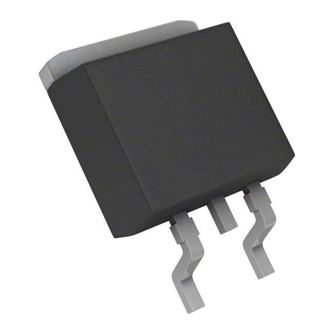
ICGOO电子元器件商城为您提供D8025L由Littelfuse设计生产,在icgoo商城现货销售,并且可以通过原厂、代理商等渠道进行代购。 D8025L价格参考。LittelfuseD8025L封装/规格:二极管 - 整流器 - 单, 标准 通孔 二极管 800V 15.9A TO-220 隔离的标片。您可以下载D8025L参考资料、Datasheet数据手册功能说明书,资料中有D8025L 详细功能的应用电路图电压和使用方法及教程。
型号为D8025L的整流二极管由Littelfuse Inc.生产,属于单整流器二极管,主要应用于需要将交流电转换为直流电的电路中。该器件常用于电源、充电器、适配器及各类电子设备中,以确保电流仅在一个方向流动,从而保护电路免受反向电压损害。此外,D8025L还可用于逆变器、马达驱动、开关电源和工业控制系统等场景。由于其具备较高的反向耐压能力和较大的正向电流承载能力,适合在中高功率应用中使用。
| 参数 | 数值 |
| 产品目录 | |
| 描述 | DIODE GEN PURP 800V 15.9A TO220整流器 800V 25A |
| 产品分类 | 单二极管/整流器分离式半导体 |
| 品牌 | Littelfuse |
| 产品手册 | |
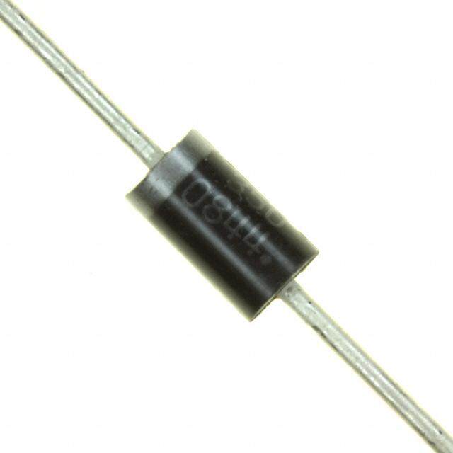
| 产品图片 |
|
| rohs | 符合RoHS无铅 / 符合限制有害物质指令(RoHS)规范要求 |
| 产品系列 | 二极管与整流器,整流器,Littelfuse D8025L- |
| 数据手册 | |
| 产品型号 | D8025L |
| 不同If时的电压-正向(Vf) | 1.6V @ 15.9A |
| 不同 Vr、F时的电容 | - |
| 不同 Vr时的电流-反向漏电流 | 20µA @ 800V |
| 二极管类型 | 标准 |
| 产品 | Ultra Fast Recovery Rectifiers |
| 产品种类 | 整流器 |
| 供应商器件封装 | TO-220 隔离的标片 |
| 其它名称 | D8025L-ND |
| 包装 | 散装 |
| 反向恢复时间(trr) | 4µs |
| 反向电压 | 800 V |
| 反向电流IR | 0.1 mA |
| 商标 | Littelfuse |
| 安装类型 | 通孔 |
| 安装风格 | Through Hole |
| 封装 | Bulk |
| 封装/外壳 | TO-220-3 隔离片 |
| 封装/箱体 | TO-220-3 FP |
| 工作温度-结 | -40°C ~ 125°C |
| 工厂包装数量 | 500 |
| 恢复时间 | 4 us |
| 最大工作温度 | + 125 C |
| 最大浪涌电流 | 350 A |
| 最小工作温度 | - 40 C |
| 标准包装 | 500 |
| 正向电压下降 | 1.6 V |
| 正向连续电流 | 15.9 A |
| 热阻 | 2.5°C/W Jc |
| 电压-DC反向(Vr)(最大值) | 800V |
| 电流-平均整流(Io) | 15.9A |
| 速度 | 标准恢复 >500ns,> 200mA(Io) |
| 配置 | Single |


- 商务部:美国ITC正式对集成电路等产品启动337调查
- 曝三星4nm工艺存在良率问题 高通将骁龙8 Gen1或转产台积电
- 太阳诱电将投资9.5亿元在常州建新厂生产MLCC 预计2023年完工
- 英特尔发布欧洲新工厂建设计划 深化IDM 2.0 战略
- 台积电先进制程称霸业界 有大客户加持明年业绩稳了
- 达到5530亿美元!SIA预计今年全球半导体销售额将创下新高
- 英特尔拟将自动驾驶子公司Mobileye上市 估值或超500亿美元
- 三星加码芯片和SET,合并消费电子和移动部门,撤换高东真等 CEO
- 三星电子宣布重大人事变动 还合并消费电子和移动部门
- 海关总署:前11个月进口集成电路产品价值2.52万亿元 增长14.8%


PDF Datasheet 数据手册内容提取
Teccor® brand Thyristors 15 / 20 / 25 Amp Rectifiers Dxx15L & Dxx20L & Dxx25L Series RoHS Description Silicon rectifiers that are excellent for DC phase control applications with motor loads. Isolated mounting tab allows for use in circuits with common anode or common cathode connections. Features & Benefits • RoHS Compliant • Surge capability up to 350 A • Glass – passivated junctions • Voltage capability up to 1000 V Agency Approval Agency Agency File Number Applications L Package : E71639 Typical applications are AC to DC solid-state switches for industrial power tools, exercise equipment, white goods, and commercial appliances. Schematic Symbol Internally constructed isolated package is offered for ease of heat sinking with highest isolation voltage. A K Main Features Symbol Value Unit Additional Information I 15 / 20 / 25 A T(RMS) V 400 to 1000 V RRM Datasheet Resources Samples Absolute Maximum Ratings Value Symbol Parameter Test Conditions Unit Dxx15L Dxx20L Dxx25L I RMS forward current 15 20 25 A F(RMS) Dxx15L: T = 90°C C IF(AV) Average forward current Dxx20L/Dxx25L: TC = 80°C 9.5 12.7 15.9 A single half cycle; f = 50Hz; 188 255 300 T (initial) = 25°C I Peak non-repetitive surge current J A FSM single half cycle; f = 60Hz; 225 300 350 T (initial) = 25°C J I2t I2t Value for fusing t = 8.3 ms 210 374 508 A2s p T Storage temperature range -40 to 150 °C stg T Operating junction temperature range -40 to 125 °C J Note: xx = voltage © 2016 Littelfuse, Inc. Specifications are subject to change without notice. Revised: 05/02/16
Teccor® brand Thyristors 15 / 20 / 25 Amp Rectifiers Electrical Characteristics (T = 25°C, unless otherwise specified) J Symbol Parameter Test Conditions Value Unit t Reverse-recovery Time I=0.9A, I =1.5A TYP. 4 μs rr F R Static Characteristics Symbol Test Conditions Value Unit 15A Device I = 30A; t = 380μs T p V 20A Device I = 40A; t = 380μs MAX. 1.6 V FM T p 25A Device I = 50A; t = 380μs T p 400-600V 10 T = 25°C J 800-1000V 20 I V 400-800V MAX. 500 μA RM RRM T = 100°C J 1000V 3000 T = 125°C 400-800V 1000 J Thermal Resistances Symbol Parameter Value Unit Dxx15L 2.60 R Junction to case (AC) Dxx20L 2.55 °C/W θ(J-C) Dxx25L 2.50 Note: xx = voltage Figure 1: On-State Current vs. On-State Figure 2: Power Dissipation vs. Average Forward On- Voltage (Typical) State Current (Typical) 160 20 s p Current (i) – AmF 111024000 TJ = 25°C Dxx25L Dxx20L wer DissipationWatts) 1126 Dxx15L Dxx20L Dxx25L eous Forward 468000 Dxx15L ge Forward Po] - ( [PF(AV) 8 antan 20 Avera 4 Single pulse rectification st 60Hz sine wave n I 0 0 0.7 0.8 0.9 1.0 1.1 1.2 1.3 1.4 1.5 1.6 1.7 1.8 0 2 4 68 1 0 12 14 16 Instantaneous Forward Voltage (v) – Volts Average Forward Current [I ] - Amps F F(AV) © 2016 Littelfuse, Inc. Specifications are subject to change without notice. Revised: 05/02/16
Teccor® brand Thyristors 15 / 20 / 25 Amp Rectifiers Figure 3: Maximum Allowable Case Temperature vs. Figure 4: Surge Peak On-State Current vs. Average On-State Current Number of Cycles 130 1000 125 120 Maximum Allowable Case Temperature (T) - °CC111100118990505505 Dxx15L Dxx25L Peak Surge (Non-repetitive)Forward Current (I) – AmpsFSM 10100 Dxx15L Dxx25L Dxx20L 80 CURRENT WAVEFORM: Sinusoidal LOAD: Resistive or Inductive Dxx20L 75 CONDUCTION ANGLE: 180° 1 70 1 10 100 1000 0 2 4 6 8 10 12 14 16 18 Surge Current Duration -- Full Cycles Average Forward Current [I ] - Amps F(AVE) Supply Frequency: 60Hz Sinusoidal Note: xx = voltage Load: Resistive RMS Forward Current : [I ]: Maximum Rated T(RMS) Value at Specific Case Temperature Soldering Parameters Reflow Condition Pb – Free assembly t P T P - Temperature Min (Ts(min)) 150°C e RRaammpp--uupp Pre Heat -- TTeimmep e(mraitnu rteo Mmaaxx )( T(ts()max)) 2600 0–° C180 secs rutare TS(mTaxL) tL s p m RRaammpp--ddoown Average ramp up rate (Liquidus Temp) PPrreehheeaatt 5°C/second max e (TL) to peak T TS(min) t T to T - Ramp-up Rate 5°C/second max S S(max) L - Temperature (T) (Liquidus) 217°C Reflow L 25 - Temperature (tL) 60 – 150 seconds time to peak temperature Time Peak Temperature (T) 260+0/-5 °C P Time within 5°C of actual peak 20 – 40 seconds Temperature (t) p Ramp-down Rate 5°C/second max Time 25°C to peak Temperature (T) 8 minutes Max. P Do not exceed 280°C © 2016 Littelfuse, Inc. Specifications are subject to change without notice. Revised: 05/02/16
Teccor® brand Thyristors 15 / 20 / 25 Amp Rectifiers Physical Specifications Environmental Specifications Test Specifications and Conditions Terminal Finish 100% Matte Tin Plated High Temperature MIL-STD-750: Method 1040, Condition A Voltage Blocking Rated V , 125°C, 1008 hours UL recognized epoxy meeting flammability RRM Body Material MIL-STD-750: Method 1051 classification 94V-0 Temperature Cycling -40°C to 150°C, 15-minute dwell, 100 cycles Lead Material Copper Alloy Biased Temperature & EIA/JEDEC: JESD22-A101 Humidity 320VDC, 85°C, 85%RH, 1008 hours MIL-STD-750: Method 1031 High Temp Storage 150°C, 1008 hours Design Considerations Low-Temp Storage 1008 hours; -40°C Careful selection of the correct device for the application’s Resistance to MIL-STD-750: Method 2031 operating parameters and environment will go a long way Solder Heat 260°C, 10 seconds toward extending the operating life of the rectifier. Good Solderability ANSI/J-STD-002, Category 3, Test A design practice should limit the maximum continuous current through the main terminals to 75% of the device Lead Bend MIL-STD-750: Method 2036, Condition E rating. Other ways to ensure long life for a power discrete semiconductor are proper heat sinking and selection of voltage ratings for worst case conditions. Overheating, overvoltage (including dv/dt), and surge currents are the main killers of semiconductors. Correct mounting, soldering, and forming of the leads also help protect against component damage. Dimensions — TO-220AB (L-Package) — Isolated Mounting Tab T MEASURING POINT AREA (REF.) 0.17 IN2 Inches Millimeters C Dimension E A O P .83.2130 Min Max Min Max A 0.380 0.420 9.65 10.67 B C B 0.105 0.115 2.67 2.92 13.36 D .526 C 0.230 0.250 5.84 6.35 7.01 D 0.590 0.620 14.99 15.75 .276 E 0.142 0.147 3.61 3.73 F 0.110 0.130 2.79 3.30 F G 0.540 0.575 13.72 14.61 G R H 0.025 0.035 0.64 0.89 L J 0.195 0.205 4.95 5.21 H K 0.095 0.105 2.41 2.67 CATHODE ANODE Not Used N Note: Maximum torque to L 0.060 0.075 1.52 1.91 K be applied to mounting tab J M is 8 in-lbs. (0.904 Nm). M 0.085 0.095 2.16 2.41 N 0.018 0.024 0.46 0.61 O 0.178 0.188 4.52 4.78 P 0.045 0.060 1.14 1.52 R 0.038 0.048 0.97 1.22 © 2016 Littelfuse, Inc. Specifications are subject to change without notice. Revised: 05/02/16
Teccor® brand Thyristors 15 / 20 / 25 Amp Rectifiers Product Selector Voltage Part Number Type Package 400V 600V 800V 1000V Dxx15L X X X X Rectifier TO-220L Dxx20L X X X X Rectifier TO-220L Dxx25L X X X X Rectifier TO-220L Note: xx = Voltage Packing Options Part Number Marking Weight Packing Mode Base Quantity Dxx15LTP Dxx15L 2.2 g Tube 500 (50 per tube) Dxx20LTP Dxx20L 2.2 g Tube 500 (50 per tube) Dxx25LTP Dxx25L 2.2 g Tube 500 (50 per tube) Note: xx = Voltage Part Numbering System Part Marking System D 60 15 L 59 TO-220AB - (L Package) DEVICE TYPE D: Rectifier LEAD FORM DIMENSIONS xx: Lead Form Option VOLTAGE RATING 40: 400V D6015L 60: 600V YMXXX 80: 800V K0: 1000V Date Code Marking Y:Year Code PACKAGE TYPE M: Month Code CURRENT RATING L: TO-220 (Isolated) ® XXX: Lot Trace Code 15: 15A 20: 20A 25: 25A K A not used © 2016 Littelfuse, Inc. Specifications are subject to change without notice. Revised: 05/02/16