ICGOO在线商城 > 电阻器 > 芯片电阻 - 表面安装 > D2TO035CR4700FTE3
 Datasheet下载
- 型号: D2TO035CR4700FTE3
- 制造商: Vishay
- 库位|库存: xxxx|xxxx
- 要求:
| 数量阶梯 | 香港交货 | 国内含税 |
| +xxxx | $xxxx | ¥xxxx |
查看当月历史价格
查看今年历史价格
D2TO035CR4700FTE3产品简介:
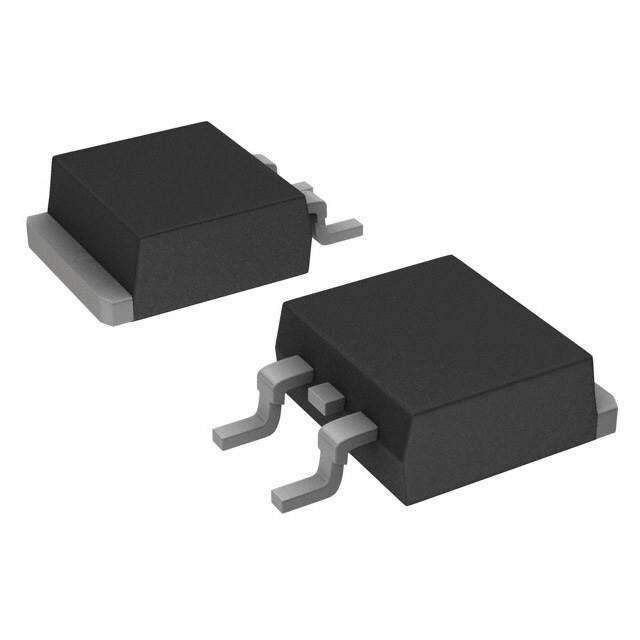
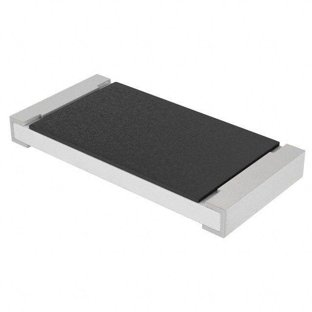
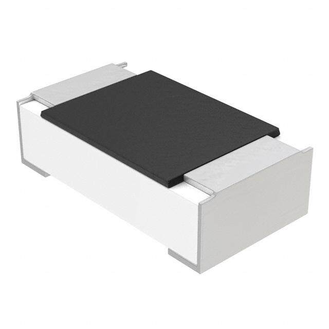
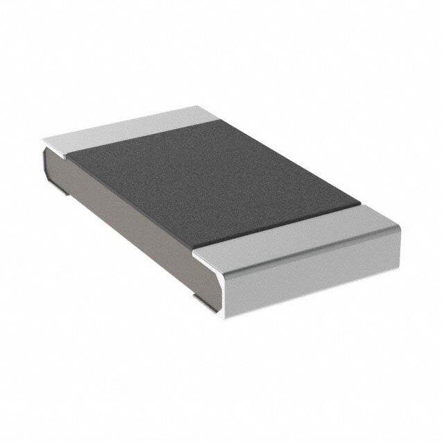
ICGOO电子元器件商城为您提供D2TO035CR4700FTE3由Vishay设计生产,在icgoo商城现货销售,并且可以通过原厂、代理商等渠道进行代购。 D2TO035CR4700FTE3价格参考。VishayD2TO035CR4700FTE3封装/规格:芯片电阻 - 表面安装, 470 mOhms ±1% 35W 厚膜 芯片电阻 TO-263-3,D²Pak(2 引线 + 接片),TO-263AB 汽车级 AEC-Q200,防潮,非电感 厚膜。您可以下载D2TO035CR4700FTE3参考资料、Datasheet数据手册功能说明书,资料中有D2TO035CR4700FTE3 详细功能的应用电路图电压和使用方法及教程。
Vishay Sfernice品牌的D2TO035CR4700FTE3是一款表面贴装的薄膜芯片电阻,具有精度高、稳定性好、温度系数低等特点,适用于对电阻性能要求较高的电子设备和系统。

该型号电阻的典型应用场景包括:

1. 工业控制设备:用于PLC(可编程逻辑控制器)、传感器模块、工业仪表等,提供高精度信号采样和稳定的工作性能。

2. 通信设备:应用于基站、光模块、路由器和交换机等通信基础设施中,支持高频率信号处理和稳定传输。

3. 汽车电子系统:如发动机控制单元(ECU)、车载传感器、ADAS(高级驾驶辅助系统)等,满足汽车环境对可靠性和温度稳定性的严苛要求。

4. 医疗电子设备:用于诊断仪器、监护设备和便携式医疗设备中,确保测量精度和长期稳定性。

5. 消费类电子产品:如高端音频设备、智能家电和精密电源管理模块,提供紧凑设计和高性能表现。

该电阻采用表面贴装封装,适合自动化生产,广泛应用于需要高性能和高可靠性的电路设计中。
| 参数 | 数值 |
| 产品目录 | |
| 描述 | RES 0.47 OHM 35W 1% D2PAK厚膜电阻器 - SMD 35W 0.47ohm 1% |
| 产品分类 | |
| 品牌 | Vishay SferniceVishay / Sfernice |
| 产品手册 | |
| 产品图片 |
|
| rohs | RoHS 合规性豁免无铅 / 符合限制有害物质指令(RoHS)规范要求 |
| 产品系列 | 薄膜电阻器,厚膜电阻器 - SMD,Vishay / Sfernice D2TO035CR4700FTE3D2TO35 |
| 数据手册 | |
| 产品型号 | D2TO035CR4700FTE3D2TO035CR4700FTE3 |
| 产品 | Thick Film Resistors SMD |
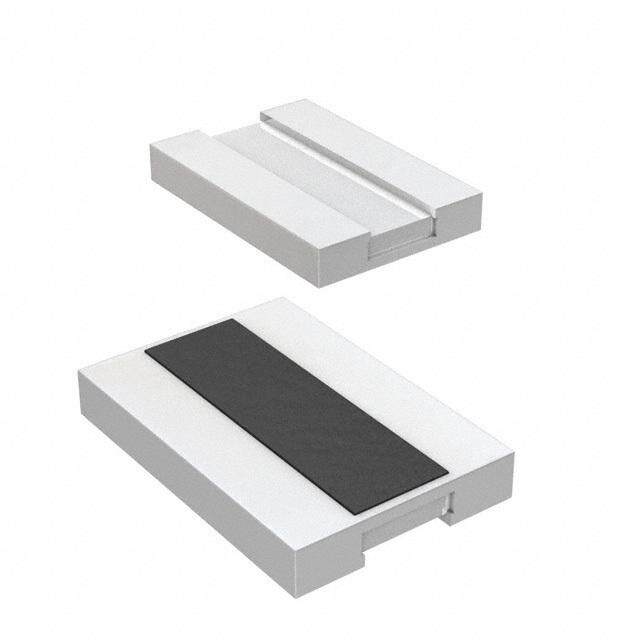
| 产品目录绘图 |
|
| 产品目录页面 | |
| 产品种类 | 厚膜电阻器 - SMD |
| 供应商器件封装 | TO-263 (D²Pak) |
| 其它名称 | D2TO 35 C U47 1% TU50 E3 |
| 功率(W) | 35W |
| 功率额定值 | 35 W |
| 包装 | 管件 |
| 商标 | Vishay / Sfernice |
| 外壳宽度 | 8.8 mm |
| 外壳长度 | 10.1 mm |
| 外壳高度 | 4.5 mm |
| 大小/尺寸 | 0.398" 长 x 0.346" 宽(10.10mm x 8.80mm) |
| 容差 | ±1%1 % |
| 封装 | Tube |
| 封装/外壳 | TO-263-3,D²Pak(2 引线+接片),TO-263AB |
| 封装/箱体 | TO-263 (D2PAK) |
| 工作温度范围 | - 55 C to + 175 C |
| 工厂包装数量 | 50 |
| 成分 | 厚膜 |
| 标准包装 | 50 |
| 温度系数 | ±250ppm/°C250 PPM / C |
| 特性 | 获得 AEC-Q200 汽车认证,无电感 |
| 特色产品 | http://www.digikey.com/cn/zh/ph/Vishay/D2TO35.html |
| 电压额定值 | 250 V |
| 电阻 | 0.47 Ohms |
| 电阻(Ω) | 0.47 |
| 端子数 | 2 |
| 类型 | Surface Mounted Power Resistor Thick Film Technology |
| 系列 | D2TOxx |
| 高度 | 0.189"(4.80mm) |


PDF Datasheet 数据手册内容提取
D2TO35 www.vishay.com Vishay Sfernice Surface Mount Power Resistor Thick Film Technology FEATURES • AEC-Q200 qualified • 35 W at 25 °C case temperature • Surface mounted resistor - TO-263 (D2PAK) style package • Wide resistance range from 0.01 to 550 k • Non inductive • Resistor isolated from metal tab DESIGN SUPPORT TOOLS click logo to get started • Solder reflow secure at 270 °C/10 s • Material categorization: for definitions of compliance Models please see www.vishay.com/doc?99912 Available DIMENSIONS in millimeters 4.5 1.25 Footprint recommendation for 10.5 8.7 solderable contact area: 7.8 min. 5 1.2 11.00 1.6 1.50 4.02 0.2 1 5 8. 10.1 8.8 1 6.50 5. 4 8.00 5. 7.6 1 4.00 2.49 2.8 2.2 5 2.40 1.6 0.3 5.08 0.26 2 Tolerance: ± 0.3 mm 4.5 Notes • For the assembly on board, we recommend the lead (Pb)-free thermal profile as per J-STD-020C • Power dissipation is 3.5 W at an ambient temperature of 25 °C when mounted on a double sided copper board using FR4 HTG, 70 μm of copper, 39 mm x 30 mm x 1.6 mm, with thermal vias STANDARD ELECTRICAL SPECIFICATIONS RESISTANCE RATED POWER LIMITING ELEMENT TEMPERATURE CRITICAL TOLERANCE MODEL SIZE RANGE P VOLTAGE U COEFFICIENT RESISTANCE 25 °C L ± % W V ± ppm/°C D2TO35 TO-263 0.01 to 550K 35 500 1, 2, 5, 10 150, 250, 700, 1100 7.14K MECHANICAL SPECIFICATIONS TECHNICAL SPECIFICATIONS Mechanical Protection Molded Power Rating and 35 W at 25 °C (case Thermal Resistance temperature) Resistive Element Thick film of the Component R : 4.28 °C/W TH (j - c) Substrate Alumina Temperature Coefficient See Special Feature table Connections Tinned copper Standard ± 150 ppm/°C Weight 2.2 g max. Dielectric Strength 2000 VRMS - 1 min - 10 mA max. IEC 60115-1 (between terminals and board) ENVIRONMENTAL SPECIFICATIONS Insulation Resistance 106 M Temperature Range -55 °C to +175 °C Inductance 0.1 μH IEC 60695-11-5 DIMENSIONS Flammability 2 applications 30 s separated by 60 s Standard Package TO-263 style (D2PAK) Revision: 29-Mar-16 1 Document Number: 51058 For technical questions, contact: sferfixedresistors@vishay.com THIS DOCUMENT IS SUBJECT TO CHANGE WITHOUT NOTICE. THE PRODUCTS DESCRIBED HEREIN AND THIS DOCUMENT ARE SUBJECT TO SPECIFIC DISCLAIMERS, SET FORTH AT www.vishay.com/doc?91000
D2TO35 www.vishay.com Vishay Sfernice SPECIAL FEATURES Resistance Values 0.010 0.045 0.1 0.5 Tolerances ± 1 % at ± 10 % Requirement Temperature Coefficient (TCR) (-55 °C +150 °C) ± 1100 ppm/°C ± 700 ppm/°C ± 250 ppm/°C ± 150 ppm/°C IEC 60115-1 PERFORMANCE TESTS CONDITIONS REQUIREMENTS IEC 60115-1 §4.13 1.7 Pr 5 s for R < 2 Momentary Overload ± (0.25 % + 0.005 ) 1.4 Pr 5 s for R 2 US < 1.5 UL IEC 60115-1 Load Life ± (1 % + 0.005 ) 1000 h, 90/30 Pr at +25 °C AEC-Q200 REV D conditions: High Temperature Exposure MIL-STD-202 method 108 ± (0.25 % + 0.005 ) 1000 h, +175 °C, unpowered Pre-conditioning 3 reflows according JESTD020D Temperature Cycling IEC 60068-2-14 test Na ± (0.5 % + 0.005 ) 1000 cycles, -55 °C, +175 °C Dwell time - 15 min AEC-Q200 REV D conditions: Moisture Resistance MIL-STD-202 method 106 ± (0.5 % + 0.005 ) 10 cycles, 24 h, unpowered AEC-Q200 REV D conditions: Biased Humidity MIL-STD-202 method 103 ± (1 % + 0.005 ) 1000 h, 85 °C, 85% RH AEC-Q200 REV D conditions: Pre-conditioning 3 reflows according Operational Life JESTD020D ± (1 % + 0.005 ) MIL-STD-202 method 108 2000 h, 90/30, powered, +125 °C AEC-Q200 REV D conditions: ESD Human Body Model AEC-Q200-002 ± (0.5 % + 0.005 ) 25 kV AD AEC-Q200 REV D conditions: MIL-STD-202 method 204 Vibration ± (0.5 % + 0.005 ) 5 g’s for 20 min, 12 cycles test from 10 Hz to 2000 Hz AEC-Q200 REV D conditions: MIL-STD-202 method 213 Mechanical Shock ± (0.5 % + 0.005 ) 100 g’s, 6 ms, 3.75 m/s 3 shocks/direction AEC-Q200 REV D conditions: Board Flex AEC-Q200-005 ± (0.25 % + 0.01 ) bending 2 mm, 60 s AEC-Q200 REV D conditions: Terminal Strength AEC-Q200-006 ± (0.25 % + 0.01 ) 1.8 kgf, 60 s ASSEMBLY SPECIFICATIONS For the assembly on board, we recommend the lead (Pb)-free thermal profile as per J-STD-020C TESTS CONDITIONS REQUIREMENTS IEC 60115-1 Resistance to Soldering Heat IEC 60068-2-58 ± (0.5 % + 0.005 ) Solder bath method: 270 °C/10 s Level: 1 IPC/JEDEC® J-STD-020C Moisture Sensitivity Level (MSL) + pass requirements of TCR 85 °C/85 % RH/168 h overload and dielectric strength after MSL Revision: 29-Mar-16 2 Document Number: 51058 For technical questions, contact: sferfixedresistors@vishay.com THIS DOCUMENT IS SUBJECT TO CHANGE WITHOUT NOTICE. THE PRODUCTS DESCRIBED HEREIN AND THIS DOCUMENT ARE SUBJECT TO SPECIFIC DISCLAIMERS, SET FORTH AT www.vishay.com/doc?91000
D2TO35 www.vishay.com Vishay Sfernice CHOICE OF THE BOARD The user must choose the board according to the working conditions of the component (power, room temperature). Maximum working temperature must not exceed 175 °C. The dissipated power is simply calculated by the following ratio: T 1 P = ------------------------------------------------------------------------------------------- R +R +R TH (j - c) TH (c - h) TH (h - a) P: Expressed in W T: Difference between maximum working temperature and room temperature or fluid cooling temperature R : Thermal resistance value measured between resistive layer and outer side of the resistor. It is the thermal resistance TH (j - c) of the component: 4.28 °C/W. R : Thermal resistance value measured between outer side of the resistor and upper side of the board. This is the thermal TH (c - h) resistance of the solder layer. R : Thermal resistance of the board. TH (h - a) Example: R + R for D2TO35 power rating 3.5 W at ambient temperature +25 °C. TH (c - h) TH (h - a) Thermal resistance R : 4.28 °C/W TH (j - c) Considering equation (1) we have: T = 175 °C - 25 °C = 150 °C R + R + R = T/P = 150/3.5 = 42.8 °C/W TH (j - c) TH (c - h) TH (h - a) R + R = 42.8 °C/W - 4.28 °C/W = 38.52 °C/W TH (c - h) TH (h - a) Single Pulse: These informations are for a single pulse on a cold resistor at 25 °C (not already used for a dissipation) and for pulses of 100 ms maximum duration. The formula used to calculate E is: 2 U E = P x t = -------- x t R with: E (J): Pulse energy P (W): Pulse power t (s): Pulse duration U (V): Pulse voltage R (W): Resistor The energy calculated must be less: than that allowed by the graph. Revision: 29-Mar-16 3 Document Number: 51058 For technical questions, contact: sferfixedresistors@vishay.com THIS DOCUMENT IS SUBJECT TO CHANGE WITHOUT NOTICE. THE PRODUCTS DESCRIBED HEREIN AND THIS DOCUMENT ARE SUBJECT TO SPECIFIC DISCLAIMERS, SET FORTH AT www.vishay.com/doc?91000
D2TO35 www.vishay.com Vishay Sfernice OVERLOADS POWER RATING In any case the applied voltage must be lower than the The temperature of the case should be maintained within the maximum overload voltage of 750 V. The values indicated limits specified. on the graph below are applicable to resistors in air or 120 mounted onto a board. ENERGY CURVE 100 % 100 N R I 75 E S 10 OW E P UL D 50 O 1 E N J RAT Y I 0.1 25 G R E N 0 E 0.01 0 20 40 60 80 100 120 140 160 175 CASE TEMPERATURE IN °C 0.001 10-7 10-6 10-5 10-4 10-3 10-2 10-1 OVERLOAD DURATION IN s PACKAGING • Reel POWER CURVE • Tube • Tape dimensions (mm) for reel: 100 000 16 5.3 W 10 000 N 16.4 24 R I E W O 1000 11 P MARKING Model, style, resistance value (in ), tolerance (in %), 100 10-7 10-6 10-5 10-4 10-3 10-2 10-1 manufacturing date, Vishay Sfernice trademark OVERLOAD DURATION IN s Revision: 29-Mar-16 4 Document Number: 51058 For technical questions, contact: sferfixedresistors@vishay.com THIS DOCUMENT IS SUBJECT TO CHANGE WITHOUT NOTICE. THE PRODUCTS DESCRIBED HEREIN AND THIS DOCUMENT ARE SUBJECT TO SPECIFIC DISCLAIMERS, SET FORTH AT www.vishay.com/doc?91000
D2TO35 www.vishay.com Vishay Sfernice ORDERING INFORMATION D2TO 35 C 100 k ± 1 % XXX e3 MODEL STYLE CONNECTIONS RESISTANCE TOLERANCE CUSTOM DESIGN LEAD (Pb)-FREE VALUE F = ± 1 % Optional on request: G = ± 2 % shape, etc. J = ± 5 % K = ± 10 % SAP PART NUMBERING GUIDELINES D 2 T O 0 3 5 C R 2 0 0 0 K R E 3 GLOBAL SIZE LEADS OHMIC VALUE TOLERANCE PACKAGING LEAD (Pb)-FREE MODEL D2TO 035 C = surface mount The first four digits are F = 1 % R = reel 500 pieces E3 = pure tin significant figures and the G = 2 % T = tube 50 pieces last digit specifies the J = 5 % number of zeros to follow. K = 10 % R designates decimal point. 48R70 = 48.7 48701 = 48 700 10002 = 100 000 R0100 = 0.01 R6800 = 0.68 27000 = 2700 = 2.7 k Revision: 29-Mar-16 5 Document Number: 51058 For technical questions, contact: sferfixedresistors@vishay.com THIS DOCUMENT IS SUBJECT TO CHANGE WITHOUT NOTICE. THE PRODUCTS DESCRIBED HEREIN AND THIS DOCUMENT ARE SUBJECT TO SPECIFIC DISCLAIMERS, SET FORTH AT www.vishay.com/doc?91000
Legal Disclaimer Notice www.vishay.com Vishay Disclaimer ALL PRODUCT, PRODUCT SPECIFICATIONS AND DATA ARE SUBJECT TO CHANGE WITHOUT NOTICE TO IMPROVE RELIABILITY, FUNCTION OR DESIGN OR OTHERWISE. Vishay Intertechnology, Inc., its affiliates, agents, and employees, and all persons acting on its or their behalf (collectively, “Vishay”), disclaim any and all liability for any errors, inaccuracies or incompleteness contained in any datasheet or in any other disclosure relating to any product. Vishay makes no warranty, representation or guarantee regarding the suitability of the products for any particular purpose or the continuing production of any product. To the maximum extent permitted by applicable law, Vishay disclaims (i) any and all liability arising out of the application or use of any product, (ii) any and all liability, including without limitation special, consequential or incidental damages, and (iii) any and all implied warranties, including warranties of fitness for particular purpose, non-infringement and merchantability. Statements regarding the suitability of products for certain types of applications are based on Vishay’s knowledge of typical requirements that are often placed on Vishay products in generic applications. Such statements are not binding statements about the suitability of products for a particular application. It is the customer’s responsibility to validate that a particular product with the properties described in the product specification is suitable for use in a particular application. Parameters provided in datasheets and / or specifications may vary in different applications and performance may vary over time. All operating parameters, including typical parameters, must be validated for each customer application by the customer’s technical experts. Product specifications do not expand or otherwise modify Vishay’s terms and conditions of purchase, including but not limited to the warranty expressed therein. Except as expressly indicated in writing, Vishay products are not designed for use in medical, life-saving, or life-sustaining applications or for any other application in which the failure of the Vishay product could result in personal injury or death. Customers using or selling Vishay products not expressly indicated for use in such applications do so at their own risk. Please contact authorized Vishay personnel to obtain written terms and conditions regarding products designed for such applications. No license, express or implied, by estoppel or otherwise, to any intellectual property rights is granted by this document or by any conduct of Vishay. Product names and markings noted herein may be trademarks of their respective owners. © 2017 VISHAY INTERTECHNOLOGY, INC. ALL RIGHTS RESERVED Revision: 08-Feb-17 1 Document Number: 91000
Mouser Electronics Authorized Distributor Click to View Pricing, Inventory, Delivery & Lifecycle Information: V ishay: D2TO035C5R000FTE3 D2TO035CR0500FTE3 D2TO035C10000FTE3 D2TO035C100R0FTE3 D2TO035C10R00FTE3 D2TO035C15R00FTE3 D2TO035C1R000FTE3 D2TO035C22R00FTE3 D2TO035C2R200FTE3 D2TO035C47R00FTE3 D2TO035CR0100FTE3 D2TO035CR0150FTE3 D2TO035CR0220FTE3 D2TO035CR0680FTE3 D2TO035CR1000FTE3 D2TO035CR4700FTE3 D2TO035C150R0JTE3 D2TO035C33000JTE3 D2TO035CR0100GTE3 D2TO035C47R00KTE3 D2TO035CR0150JRE3 D2TO035C2R700KRE3 D2TO035CR0150FRE3 D2TO035C1R000GRE3 D2TO035C200R0KTE3 D2TO035C33000FTE3 D2TO035C3R300FRE3 D2TO035C44000JTE3 D2TO035C11000KTE3 D2TO035C10001FRE3 D2TO035C12000JTE3 D2TO035C499R0FTE3 D2TO035C1R700FRE3 D2TO035CR4700FRE3