ICGOO在线商城 > 晶体,振荡器,谐振器 > 谐振器 > CSTCE12M0G55Z-R0
 Datasheet下载
- 型号: CSTCE12M0G55Z-R0
- 制造商: Murata
- 库位|库存: xxxx|xxxx
- 要求:
| 数量阶梯 | 香港交货 | 国内含税 |
| +xxxx | $xxxx | ¥xxxx |
查看当月历史价格
查看今年历史价格
CSTCE12M0G55Z-R0产品简介:
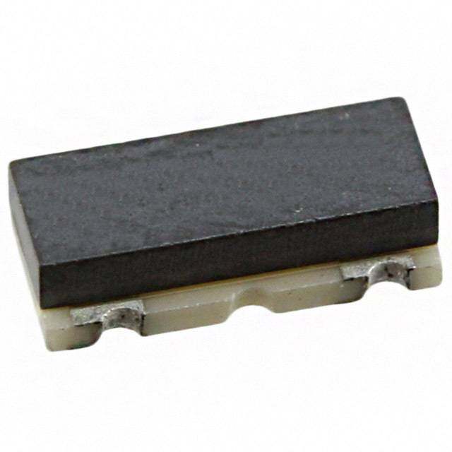
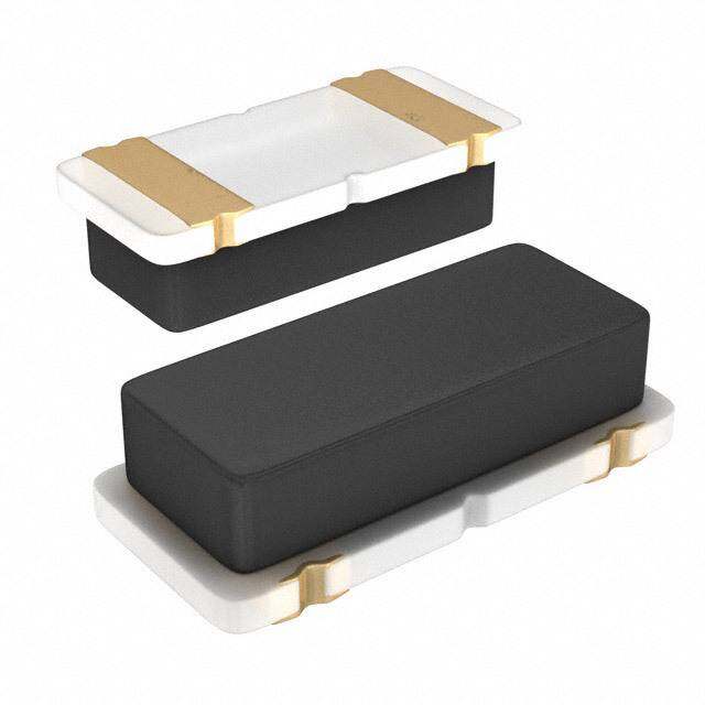
ICGOO电子元器件商城为您提供CSTCE12M0G55Z-R0由Murata设计生产,在icgoo商城现货销售,并且可以通过原厂、代理商等渠道进行代购。 CSTCE12M0G55Z-R0价格参考。MurataCSTCE12M0G55Z-R0封装/规格:谐振器, 12MHz Ceramic Resonator Built in Capacitor 33pF ±0.2% 30 Ohms -40°C ~ 125°C Surface Mount。您可以下载CSTCE12M0G55Z-R0参考资料、Datasheet数据手册功能说明书,资料中有CSTCE12M0G55Z-R0 详细功能的应用电路图电压和使用方法及教程。
Murata Electronics North America 生产的型号为 CSTCE12M0G55Z-R0 的谐振器,主要应用于需要高精度频率控制和稳定的时钟信号的电子设备中。这类谐振器通常用于以下几种应用场景:

1. 通信设备:在无线通信系统中,如手机、路由器、基站等,CSTCE12M0G55Z-R0 可以提供稳定的参考频率,确保信号传输的准确性和可靠性。它能够在复杂的电磁环境中保持良好的频率稳定性,减少干扰。

2. 消费电子产品:例如智能手表、平板电脑、蓝牙耳机等便携式设备中,该谐振器可以作为时钟源,确保设备内部各个模块之间的同步运行,提升系统的响应速度和性能。

3. 汽车电子:在现代汽车中,各种控制系统(如发动机控制单元、安全气囊系统、导航系统等)都需要精确的时间基准。CSTCE12M0G55Z-R0 以其高稳定性和抗振动特性,适合应用于这些对环境适应性要求较高的场合。

4. 工业自动化:工厂中的自动化设备、机器人控制器、传感器网络等依赖于精准的时钟信号来协调操作。这款谐振器能够保证工业设备在恶劣环境下依然保持稳定的性能表现。

5. 医疗设备:像心电图机、监护仪等医疗仪器,对于时间精度有严格的要求。CSTCE12M0G55Z-R0 能够提供可靠的频率输出,保障诊断数据的准确性。

6. 物联网 (IoT) 设备:在智能家居、智慧城市等领域,大量连接到互联网的小型设备需要稳定的时钟源来维持正常工作。该型号谐振器凭借其低功耗和小尺寸特点,非常适合这类应用。

总之,CSTCE12M0G55Z-R0 作为一种高性能的谐振器,在众多领域都有广泛的应用前景,特别是在那些对频率稳定性和可靠性要求极高的场景中。
| 参数 | 数值 |
| 产品目录 | 晶体和振荡器无源元件 |
| 描述 | CER RESONATOR 12.0MHZ SMD谐振器 12MHz 30 Ohm 5% |
| 产品分类 | |
| 品牌 | Murata Electronics |
| 产品手册 | http://search.murata.co.jp/Ceramy/CatalogAction.do?sHinnm=? &sNHinnm=CSTCE12M0G55Z-R0&sNhin_key=CSTCE12M0G55Z-R0&sLang=en&sParam=CSTCE |
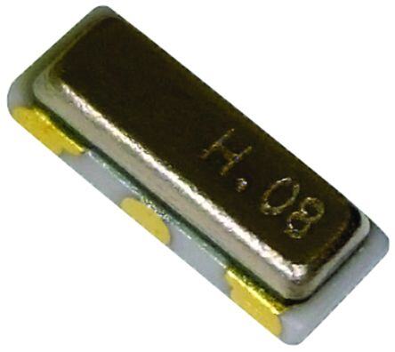
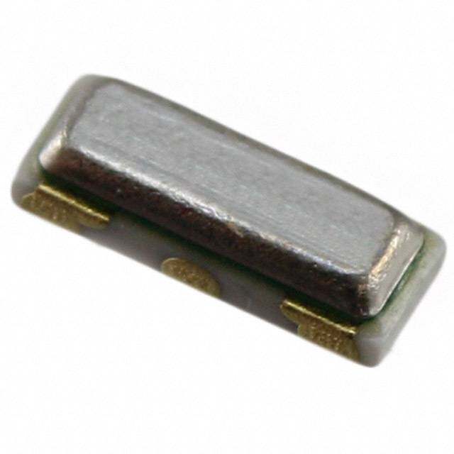
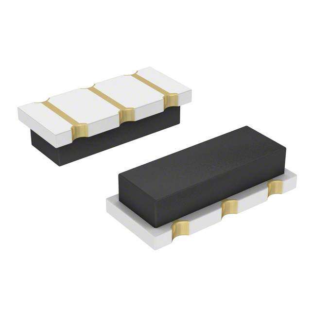
| 产品图片 |
|
| rohs | 符合RoHS无铅 / 符合限制有害物质指令(RoHS)规范要求 |
| 产品系列 | 谐振器,Murata Electronics CSTCE12M0G55Z-R0CERALOCK®, CSTCE |
| 数据手册 | |
| 产品型号 | CSTCE12M0G55Z-R0 |
| 产品目录绘图 |
|
| 产品目录页面 | |
| 产品种类 | |
| 其它名称 | 490-1220-6 |
| 包装 | Digi-Reel® |
| 商标 | Murata Electronics |
| 商标名 | CERALOCK |
| 大小/尺寸 | 0.126" 长x 0.051" 宽(3.20mm x 1.30mm) |
| 安装类型 | 表面贴装 |
| 容差 | 0.5 % |
| 封装 | Reel |
| 封装/外壳 | 3-SMD,非标准型 |
| 尺寸 | 1.1 mm W x 3 mm L x 0.7 mm H |
| 工作温度 | -40°C ~ 125°C |
| 工作温度范围 | - 20 C to + 80 C |
| 工厂包装数量 | 3000 |
| 标准包装 | 1 |
| 特性 | 内置电容 |
| 电容 | 33pF |
| 端接类型 | SMD/SMT |
| 类型 | Small-cap Chip Type |
| 系列 | CSTCE |
| 阻抗 | 30 欧姆 |
| 频率 | 12 MHz |
| 频率容差 | ±0.5% |
| 频率稳定度 | ±0.2% |
| 高度 | 0.031"(0.80mm) |


- 商务部:美国ITC正式对集成电路等产品启动337调查
- 曝三星4nm工艺存在良率问题 高通将骁龙8 Gen1或转产台积电
- 太阳诱电将投资9.5亿元在常州建新厂生产MLCC 预计2023年完工
- 英特尔发布欧洲新工厂建设计划 深化IDM 2.0 战略
- 台积电先进制程称霸业界 有大客户加持明年业绩稳了
- 达到5530亿美元!SIA预计今年全球半导体销售额将创下新高
- 英特尔拟将自动驾驶子公司Mobileye上市 估值或超500亿美元
- 三星加码芯片和SET,合并消费电子和移动部门,撤换高东真等 CEO
- 三星电子宣布重大人事变动 还合并消费电子和移动部门
- 海关总署:前11个月进口集成电路产品价值2.52万亿元 增长14.8%
PDF Datasheet 数据手册内容提取
P16E.pdf Oct.1,2018 Ceramic Resonators (CERALOCKr)
!Note • Please read rating and !CAUTION (for storage, operating, rating, soldering, mounting and handling) in this catalog to prevent smoking and/or burning, etc. P16E.pdf • This catalog has only typical specifications. Therefore, please approve our product specifications or transact the approval sheet for product specifications before ordering. Oct.1,2018 EU RoHS Compliant • All the products in this catalog comply with EU RoHS. • EU RoHS is "the European Directive 2011/65/EU on the Restriction of the Use of Certain Hazardous Substances in Electrical and Electronic Equipment." • For more details, please refer to our web page, "Murata's Approach for EU RoHS" (https://www.murata.com/en-eu/support/ compliance/rohs).
!Note (cid:129) Please read rating and !CAUTION (for storage, operating, rating, soldering, mounting and handling) in this catalog to prevent smoking and/or burning, etc. P16E.pdf (cid:129) This catalog has only typical specifications. Therefore, please approve our product specifications or transact the approval sheet for product specifications before ordering. Oct.1,2018 1 Contents Product specifications are as of October 2018. CERALOCKr, CERALOCK(R) and "CERALOCK" in this catalog are the trademarks of 2 Murata Manufacturing Co., Ltd. Selection Guide p2 Part Numbering p3 1 MHz Chip Type -Tight Frequency Tolerance for Automotive p4 3 2 MHz Chip Type -Standard Frequency Tolerance for Automotive p6 Notice for Automotive p8 Packaging for Automotive p11 4 3 MHz Chip Type -Tight Frequency Tolerance for Consumer/Industrial Usage p13 5 4 MHz Chip Type -Standard Frequency Tolerance for Consumer/Industrial Usage p15 5 MHz Lead Type -Standard Frequency Tolerance for Consumer/Industrial Usage p17 Notice for Consumer/Industrial Usage MHz Chip Type p19 MHz Lead Type p21 Packaging for Consumer/Industrial Usage MHz Chip Type p22 MHz Lead Type p24 Please check the MURATA website (https://www.murata.com/) if you cannot find a part number in this catalog.
!Note (cid:129) Please read rating and !CAUTION (for storage, operating, rating, soldering, mounting and handling) in this catalog to prevent smoking and/or burning, etc. P16E.pdf (cid:129) This catalog has only typical specifications. Therefore, please approve our product specifications or transact the approval sheet for product specifications before ordering. Oct.1,2018 Selection Guide Applications Automotive Consumer/Industrial Tight Tolerance Standard Tolerance Tight Tolerance Standard Tolerance SMD SMD SMD SMD CSTNR_GH5C CSTCR_G_B CSTNR_GH5L CSTCR_G 4.00–7.99MHz 4.00–7.99MHz 4.00–7.99MHz 4.00–7.99MHz CSTNE_G_A CSTNE_G CSTNE_GH5C CSTNE_GH5L CSTCE_G_A CSTCE_G 8.00–13.99MHz 8.00–13.99MHz 8.00–13.99MHz 8.00–13.99MHz CSTNE_V_C CSTNE_V CSTNE_VH3C CSTNE_VH3L CSTCE_V_C CSTCE_V 14.00–20.00MHz 14.00–20.00MHz 14.00–20.00MHz 14.00–20.00MHz Leaded CSTLS_G 3.40–10.00MHz CSTLS_X 16.00–70.00MHz Notice: "CERALOCKr for consumer" and "CERALOCKr for automotive" is different in the specification of Operating Temperature Range, Environmental Characteristics, Physical Characteristics and so on. Please choose either "for consumer" or "for automotive" according to the required specification. 2
!Note (cid:129) Please read rating and !CAUTION (for storage, operating, rating, soldering, mounting and handling) in this catalog to prevent smoking and/or burning, etc. P16E.pdf (cid:129) This catalog has only typical specifications. Therefore, please approve our product specifications or transact the approval sheet for product specifications before ordering. Oct.1,2018 o Part Numbering CERALOCKr (MHz) (Part Number) CS T NE 16M0 V 5 3 **** R0 1 2 3 4 5 6 7 8 9 1Product ID 7Load Capacity Product ID Code Load Capacity CS Ceramic Resonators 1 5pF 2 10pF 2Frequency/Capacitance 3 15pF Code Frequency/Capacitance 5 33/39pF T MHz with Built-in Capacitance 6 47pF 3Structure/Size 8Individual Specification Code Structure/Size Code Individual Specification LS Round Lead Type Four-digit alphanumerics express **** CR/NR/CE/NE Small-cap Chip Type "Individual Specification." With standard products, "8Individual Specification" and "9Packaging" 4Nominal Center Frequency is omitted. Expressed by four-digit alphanumerics. The unit is in hertz (Hz). Decimal point is expressed by capital letter "M." 9Packaging Code Packaging 5Design B0 Bulk Code Design A0 Radial Taping H0=18mm G Thickness Shear mode R0 Plastic Taping ø=180mm Reel V Thickness Expander mode R1 Plastic Taping ø=330mm Reel X Thickness Expander mode (3rd overtone) (cid:70)(cid:3)(cid:22)(cid:31)(cid:34)(cid:39)(cid:31)(cid:42)(cid:3)(cid:50)(cid:31)(cid:46)(cid:39)(cid:44)(cid:37)(cid:3)(cid:39)(cid:49)(cid:3)(cid:31)(cid:46)(cid:46)(cid:42)(cid:39)(cid:35)(cid:34)(cid:3)(cid:50)(cid:45)(cid:3)(cid:42)(cid:35)(cid:31)(cid:34)(cid:3)(cid:50)(cid:55)(cid:46)(cid:35)(cid:3)(cid:31)(cid:44)(cid:34)(cid:3)(cid:46)(cid:42)(cid:31)(cid:49)(cid:50)(cid:39)(cid:33)(cid:3)(cid:50)(cid:31)(cid:46)(cid:39)(cid:44)(cid:37)(cid:3)(cid:50)(cid:45)(cid:3)(cid:33)(cid:38)(cid:39)(cid:46)(cid:3)(cid:50)(cid:55)(cid:46)(cid:35)(cid:64)(cid:3) 6Initial Frequency Tolerance Code Initial Frequency Tolerance 5 ±0.5% 3 ±0.3% 2 ±0.2% H ±0.07% 3
!Note (cid:129) Please read rating and !CAUTION (for storage, operating, rating, soldering, mounting and handling) in this catalog to prevent smoking and/or burning, etc. P16E.pdf (cid:129) This catalog has only typical specifications. Therefore, please approve our product specifications or transact the approval sheet for product specifications before ordering. Oct.1,2018 Ceramic Resonators (CERALOCKr) 1 MHz Chip Type -Tight Frequency Tolerance for Automotive 4.5±0.1 Cprhoivpi dtyepse h CigEhR aAcLcOurCaKcry iwn iatnh ebxutilrte-min elolya sdm caalpl apcaictokrasg e. 30±0.20 * 2.0±0.1 1.4 max. 0. MURATA's frequency adjustment and package technology 0.2±0.2 0.6±0.05 4.1 max. eCxEpReArtLiOseC hKars wenitahb bleudil tt-hine ldoeavde cloappmaceintot rosf. the chip 1.1±0.1 0.4 (Ref.) 0.4 (Ref.) This diverse series owes its development to MURATA's 0.4 (Ref.) original mass production techniques and high reliability, (3) (2) (1) 0.4±0.1 0.4±0.1 0.4±0.1 (1): Input and has achieved importance in the worldwide automotive (2): GND (3): Output market. CSTNR_GH5C : Frequency Marking 4.00-7.99MHz * : EIAJ Monthly Code Features 0.75±0.1 1.5±0.1 1.5±0.1 (in mm) 1. High accuracy resonators whose total tolerance is 3.20±0.15 available for less than ±3,000ppm. 23.. HOisgchil lraetliioabn iclitiryc uaintds davoa niloatb rlee qfourir ea ewxitdeer nteaml lopaedra ctauprea craitnogres.. 0.10±0.10 * 1.30±0.15 1.1 max. 0.1±0.1 0.4±0.1 4. Available for a wide frequency range. 3.0 max. 0 1 5. Extremely small and have a low profile. 0±0. 7 6. No adjustment is necessary for oscillation circuits. 0. 0.50 (ref.) 0.50 (ref.) 7. Stable supply is ensured due to not using precious metal 0.50 (ref.) (3) (2) (1) (Paradium) in built-in Capacitance. 0.4±0.1 0.4±0.1 0.4±0.1 (1): Input (2): GND (3): Output CSTNE_GH5C : Frequency Marking Applications 8.00-13.99MHz * : EIAJ Monthly Code 1. Cluster panel and Control panel 0.4±0.1 1.2±0.11.2±0.1 (in mm) 2. Safety control Anti-lock Brake System, Electronic Stability Control, 3.20±0.15 3. AEnirgbiange, EeCtcU., Electronic Power Steering, Immobilizer, etc. 0.10±0.10 * 1.30±0.15 1.1 max. 4. Car Air conditioner, Power Window, 0.1±0.1 0.4±0.1 Remote Keyless Entry system, etc. 3.0 max. 0 1 0. 5. Intelligent Transportation System 0± 9 0. Lane Keeping System, Millimeter wave radar, etc. 0.50 (ref.) 0.50 (ref.) 0.50 (ref.) 6. Battery control for hybrid cars (3) (2) (1) 0.4±0.1 0.4±0.1 0.4±0.1 (1): Input (2): GND (3): Output CSTNE_VH3C : Frequency Marking 14.00-20.00MHz * : EIAJ Monthly Code 0.4±0.1 1.2±0.11.2±0.1 (in mm) Frequency Initial Frequency Shift by Temperature Operating Part Number Frequency Tolerance Temperature Range (MHz) (%) (%) (°C) CSTNR_GH5C 4.00 to 7.99 ±0.07 ±0.13 -40 to 125 CSTNE_GH5C 8.00 to 13.99 ±0.07 ±0.13 -40 to 125 CSTNE_VH3C 14.00 to 20.00 ±0.07 ±0.13 -40 to 125 Irregular or stopped oscillation may occur under unmatched circuit conditions. Please check the actual conditions prior to use. 4
!Note (cid:129) Please read rating and !CAUTION (for storage, operating, rating, soldering, mounting and handling) in this catalog to prevent smoking and/or burning, etc. P16E.pdf (cid:129) This catalog has only typical specifications. Therefore, please approve our product specifications or transact the approval sheet for product specifications before ordering. Oct.1,2018 Measuring Circuit of Oscillating Frequency 1 VDD 5pF To Frequency Counter Rf 1MΩ Rd (1) (3) C1 C2 (2) Standard Land Pattern Dimensions CSTNR_GH5C CSTNE_GH5C/CSTNE_VH3C (* This Land Pattern is not common to CSTCR_G.) 0.4 1.1 0.4 1.1 0.4 0.4 0.8 0.4 0.8 0.4 6 9 2. 1. 1.2 1.2 Land Pattern 1.5 1.5 Land Pattern (in mm) (in mm) Frequency Temperature Characteristics CSTNR_GH5C CSTNE_GH5C +0.2 +0.2 %) %) ft (+0.1 ft (+0.1 hi hi S S y y c c n n e e qu 0 qu 0 e e Fr Fr g g n n ati ati cill-0.1 cill-0.1 s s O O -0.2 -0.2 -60 -40 -20 0 +20 +40 +60 +80 +100 +120 +140 -60 -40 -20 0 +20 +40 +60 +80 +100 +120 +140 Temperature (°C) Temperature (°C) CSTNE_VH3C +0.2 %) ft (+0.1 hi S y c n e qu 0 e Fr g n ati cill-0.1 s O -0.2 -60 -40 -20 0 +20 +40 +60 +80 +100 +120 +140 Temperature (°C) 5
!Note (cid:129) Please read rating and !CAUTION (for storage, operating, rating, soldering, mounting and handling) in this catalog to prevent smoking and/or burning, etc. P16E.pdf (cid:129) This catalog has only typical specifications. Therefore, please approve our product specifications or transact the approval sheet for product specifications before ordering. Oct.1,2018 Ceramic Resonators (CERALOCKr) MHz Chip Type -Standard Frequency Tolerance for Automotive 4.5±0.1 Cprhoivpi dtyepse h CigEhR aAcLcOurCaKcry iwn iatnh ebxutilrte-min elolya sdm caalpl apcaictokrasg e. 0.3±0.2 * 2.0±0.1 1.4 max. 2 MURATA's frequency adjustment and package technology (3) (2) (1) 0.4±0.05 0.2±0.2 expertise has enabled the development of the chip 4.1 max. 5 0 CERALOCKr with built-in load capacitors. 5±0. 1 This diverse series owes its development to MURATA's 0.4 (Ref.) 0.4 (Ref.) 0.4 (Ref.) 1. 0.8±0.1 0.8±0.1 0.8±0.1 original mass production techniques and high reliability, (1): Input and has achieved importance in the worldwide automotive (2): GND (3): Output market. CSTCR_G_B : Frequency Marking 4.00-7.99MHz * : EIAJ Monthly Code 0.4±0.1 0.4±0.1 0.4±0.1 0.75±0.1 1.5±0.1 1.5±0.1 Features (in mm) 1. High reliability and available for a wide temperature range. 3.20±0.15 2. Oscillation circuits do not require external load capacitors. 34.. EAxvtarielambelely f osrm aa wll iadned f rheaqvuee an cloyw ra pnrgoefi.le. 0.10±0.10 * 1.30±0.15 1.1 max. 0.1±0.1 0.4±0.1 5. No adjustment is necessary for oscillation circuits. 3.0 max. 0 1 0. 0± 7 Applications 0.50 (ref.) 0.50 (ref.0.) 0.50 (ref.) 1. Cluster panel and Control panel (3) (2) (1) 0.4±0.1 0.4±0.1 0.4±0.1 (1): Input 2. Safety control (2): GND (3): Output Anti-lock Brake System, Electronic Stability Control, CSTNE_G_A : Frequency Marking 8.00-13.99MHz * : EIAJ Monthly Code Airbag, etc. 3. Engine ECU, Electronic Power Steering, Immobilizer, etc. 0.4±0.1 1.2±0.11.2±0.1 (in mm) 4. Car Air conditioner, Power Window, 3.20±0.15 Remote Keyless Entry system, etc. 5. Electronic Toll Collection system, Car Navigation, etc. 0.10±0.10 * 1.30±0.15 1.1 max. 0.1±0.1 0.4±0.1 3.0 max. 0 1 0. 0± 9 0. 0.50 (ref.) 0.50 (ref.) 0.50 (ref.) (3) (2) (1) 0.4±0.1 0.4±0.1 0.4±0.1 (1): Input (2): GND (3): Output CSTNE_V_C : Frequency Marking 14.00-20.00MHz * : EIAJ Monthly Code 0.4±0.1 1.2±0.11.2±0.1 (in mm) Frequency Initial Frequency Shift by Temperature Operating Part Number Frequency Tolerance Temperature Range (MHz) (%) (%) (°C) CSTCR_G_B 4.00 to 7.99 ±0.50 ±0.15 -40 to 125 CSTNE_G_A 8.00 to 13.99 ±0.50 ±0.20 -40 to 125 CSTNE_V_C 14.00 to 20.00 ±0.50 ±0.15 -40 to 125 Irregular or stopped oscillation may occur under unmatched circuit conditions. Please check the actual conditions prior to use. 6
!Note (cid:129) Please read rating and !CAUTION (for storage, operating, rating, soldering, mounting and handling) in this catalog to prevent smoking and/or burning, etc. P16E.pdf (cid:129) This catalog has only typical specifications. Therefore, please approve our product specifications or transact the approval sheet for product specifications before ordering. Oct.1,2018 Measuring Circuit of Oscillating Frequency CSTNE_G_A/CSTNE_V_C/CSTCR_G_B VDD 5pF To Frequency Counter Rf 1MΩ Rd 2 (1) (3) C1 C2 (2) Standard Land Pattern Dimensions CSTCR_G_B CSTNE_G_A/CSTNE_V_C 0.8 0.7 0.8 0.7 0.8 0.4 0.8 0.4 0.8 0.4 66 2.1. 9 1. 0.4 0.4 0.4 1.5 1.5 1.2 1.2 Land Pattern Land Pattern (in mm) (in mm) Frequency Temperature Characteristics CSTCR_G_B CSTNE_G_A +0.2 +0.2 %) %) ft (+0.1 ft (+0.1 hi hi S S y y c c n n e e qu 0 qu 0 e e Fr Fr g g n n ati ati cill-0.1 cill-0.1 s s O O -0.2 -0.2 -60 -40 -20 0 +20 +40 +60 +80 +100 +120 +140 -60 -40 -20 0 +20 +40 +60 +80 +100 +120 +140 Temperature (°C) Temperature (°C) CSTNE_V_C +0.2 %) ft (+0.1 hi S y c n e qu 0 e Fr g n ati cill-0.1 s O -0.2 -60 -40 -20 0 +20 +40 +60 +80 +100 +120 +140 Temperature (°C) 7
!Note (cid:129) Please read rating and !CAUTION (for storage, operating, rating, soldering, mounting and handling) in this catalog to prevent smoking and/or burning, etc. P16E.pdf (cid:129) This catalog has only typical specifications. Therefore, please approve our product specifications or transact the approval sheet for product specifications before ordering. Oct.1,2018 Notice for Automotive Soldering and Mounting (CSTCR_G_B/CSTNR_GH5C, CSTNE_G_A/GH5C, CSTNE_V_C/VH3C Series) 1. Soldering (1) Reflow soldering Please mount the component on a circuit board by reflow soldering. Flow soldering is not acceptable. Recommendable Flux and Solder Please use rosin based flux, Flux not water soluble flux. Peak Please use solder (Sn-3.0Ag-0.5Cu) under 260 Solder the following conditions: Standard thickness C) 245 of soldering paste: 0.10 to 0.15mm. ure (° 212800 (2H20e°aCt imngin.) at 150 Recommendable Soldering Profile mper (1P5r0e -thoe 1a8ti0n°gC) Gradual e Pre-heating 150 to 180°C 60 to 120s T Cooling Heating 220°C min. 30 to 60s upper limit: 260°C 1s max. Peak Temperature lower limit: 245°C 5s max. 60 to 120s 30 to 60s Temperature shall be measured on the surface of component. (2) Soldering with Iron If compelled to mount the component by using a soldering iron, please do not directly touch the component with the soldering iron. The component terminals or electrical characteristics may be damaged if excessive thermal stress is applied. Recommendable Soldering with Iron Heating of the soldering iron 350°C max. Watt 30W max. Shape of the soldering iron ø3mm max. Soldering Time 5s max. at one terminal Solder Sn-3.0Ag-0.5Cu (3) Solder Volume Please make the solder volume less than the height of the substrate to avoid damage to the seal between the metal cap and the substrate. (4) Other Do not reuse components removed from a circuit board after soldering. (5) Conditions for Placement Machines The component is recommended with placement machines that employ optical placement capabilities. The component may be damaged by excessive mechanical force. Please make sure that you have evaluated by using placement machines before going into mass production. Do not use placement machines that utilize mechanical positioning. Please contact Murata for details beforehand. Continued on the following page. 8
!Note (cid:129) Please read rating and !CAUTION (for storage, operating, rating, soldering, mounting and handling) in this catalog to prevent smoking and/or burning, etc. P16E.pdf (cid:129) This catalog has only typical specifications. Therefore, please approve our product specifications or transact the approval sheet for product specifications before ordering. Oct.1,2018 Notice for Automotive Continued from the preceding page. 2. Wash (1) Cleaning Solvents HCFC, Isopropanol, Tap water, Demineralized water, Cleanthrough750H, Pine alpha 100S, Techno care FRW (2) Temperature Difference : dT *1 dT=<60°C (dT=Component-solvent) *1 ex. If the component is immersed at +90°C into cleaning solvent at +60°C, then dT=30°C. (3) Conditions (a) Ultrasonic Wash (b) Immersion Wash 1 minute max. in above solvent at +60°C max. 5 minutes max. in above solvent at +60°C max. (Frequency: 28kHz, Output: 20W/l) (c) Shower or Rinse Wash 5 minutes max. in above solvent at +60°C max. (4) Drying 5 minutes max. by blowing air at +80°C max. (5) Other (a) Total washing time should be within 10 minutes. (b) The component may be damaged if it is washed with chlorine, petroleum, or alkali cleaning solvent. 3. Coating Conformal coating of the component is acceptable. However, the resin material, curing temperature, and other process conditions should be evaluated to confirm stable electrical characteristics are maintained. Continued on the following page. 9
!Note (cid:129) Please read rating and !CAUTION (for storage, operating, rating, soldering, mounting and handling) in this catalog to prevent smoking and/or burning, etc. P16E.pdf (cid:129) This catalog has only typical specifications. Therefore, please approve our product specifications or transact the approval sheet for product specifications before ordering. Oct.1,2018 Notice for Automotive Continued from the preceding page. Storage and Operating Conditions 1. Product Storage Conditions (2) Please do not put the products directly on the Please store the products in a room where the floor without anything under them to avoid damp temperature/humidity is stable, and avoid and/or dusty places. places where there are large temperature changes. (3) Please do not store the products in places Please store the products under the following such as: in a damp heated place, in a place where conditions: direct sunlight comes in, in a place applying Temperature: -10 to +40°C vibrations. Humidity: 15 to 85% R.H. (4) Please use the products immediately after the 2. Expiration Date on Storage package is opened, because the characteristics Expiration date (shelf life) of the products is six may be reduced in quality, and/or be degraded in months after delivery under the conditions of a the solderability due to storage under poor sealed and unopened package. Please use the products conditions. within six months after delivery. If you store the (5) Please do not drop the products to avoid cracking products for a long time (more than six months), of ceramic elements. use carefully because the products may be degraded 4. Other in solderability and/or rusty. Conformal coating of the component is acceptable. Please confirm solderability and characteristics However, the resin material, curing temperature, and for the products regularly. other process conditions should be evaluated to 3. Notice on Product Storage confirm that stable electrical characteristics are (1) Please do not store the products in a chemical maintained. atmosphere (Acids, Alkali, Bases, Organic gas, Please be sure to consult with our sales representatives Sulfides and so on), because the characteristics or engineers whenever and prior to using the products. may be reduced in quality, and/or be degraded in the solderability due to storage in a chemical atmosphere. Rating The component may be damaged if excessive mechanical stress is applied. Handling "CERALOCK" may stop oscillating or oscillate irregularly under improper circuit conditions. 10
!Note (cid:129) Please read rating and !CAUTION (for storage, operating, rating, soldering, mounting and handling) in this catalog to prevent smoking and/or burning, etc. P16E.pdf (cid:129) This catalog has only typical specifications. Therefore, please approve our product specifications or transact the approval sheet for product specifications before ordering. Oct.1,2018 Packaging for Automotive Minimum Quantity Part Number Plastic Tape ø180mm Plastic Tape ø330mm Bulk Reel Dimensions CSTCR_G_B 3,000 9,000 500 a CSTNR_GH5C 3,000 9,000 500 a CSTNE_G_A 3,000 9,000 500 b CSTNE_GH5C 3,000 9,000 500 b CSTNE_V_C 3,000 9,000 500 b CSTNE_VH3C 3,000 9,000 500 b The order quantity should be an integral multiple of the "Minimum Quantity" shown above. (pcs.) Dimensions of Reel a b Trailer Leader 160-190 Cover Film 16Tr0a-i1le9r0 LeaCdoevrer Film Empty Components Empty Empty Components Empty 160 min. 160 min. 00 )–1.5 400-560 00 )–1.5 400-560 8 8 1 1 (ø ø13.0±0.22.0±0.5 (ø ø13.0±0.2 2.0±0.5 13.0+ 01.0 9.0+ 01.0 17.0±1.0 13.0±1.0 (in mm) Dimensions of Taping CSTNR_GH5C CSTNE_GH5C 4.0±0.1 2.0±0.05 ø1.5+-00.1 1.75±0.1 4.0±0.1 2.0±0.05 ø1.5 +-00..01 1.75±0.1 5 5 (9.5) (3)(2)(1) 4.7±0.1 5.5±0.0 12.0±0.2 (5.2) (3)(2)(1) +0.103.40 -0.05 3.5±0.0 8.0±0.2 4.0±0.1 ø1.5±0.1 4.0±0.1 ø1.0 +-00..02 +0.10 Cover film peel strength force 0.1 to 0.7N 2.2±0.1 Cover film peel strength force 0.1 to 0.7N 1.50 -0.05 Cover film peel speed 31000°mm/min. Cover Film (5°) 0.25±0.05 1.25±0.1 (1.85 max.) Cover film peel sp1e0ed° 300mm/min. Cover Film (7˚) 0.25±0.050.90±0.10 (1.30 max.) Direction of Feed (in mm) Direction of Feed (in mm) CSTNE_VH3C 4.0±0.1Di2m.0e±n0s.i0on5s of Carrierø T1a.5p+-e00..10 75±0.1 1. 5 0 (5.2) (2)(3)(1) +0.103.40-0.05 3.5±0. 8.0±0.2 4.0±0.1 ø1.0+-00..20 +0.10 Cover film peel strength force 0.1 to 0.7N 1.50-0.05 Cover film peel speed 300mm/m10in°. Cover Film (5°) 0.25±0.05 1.10±0.10 1.40 max.) ( Direction of Feed (in mm) Continued on the following page. 11
!Note (cid:129) Please read rating and !CAUTION (for storage, operating, rating, soldering, mounting and handling) in this catalog to prevent smoking and/or burning, etc. P16E.pdf (cid:129) This catalog has only typical specifications. Therefore, please approve our product specifications or transact the approval sheet for product specifications before ordering. Oct.1,2018 Packaging for Automotive Continued from the preceding page. Dimensions of Taping CSTCR_G_B CSTNE_G_A 4.0±0.1 2.0±0.05 ø1.5+-00.1 1.75±0.1 4.0±0.1 2.0±0.05 ø1.5 +-00..01 1.75±0.1 5 5 (9.5) (3)(2)(1) 4.7±0.1 5.5±0.0 12.0±0.2 (5.2) (3)(2)(1) +0.103.40 -0.05 3.5±0.0 8.0±0.2 4.0±0.1 ø1.5+-00.1 4.0±0.1 ø1.0 +-00..02 +0.10 Cover film peel strength force 0.1 to 0.7N 2.2±0.1 Cover film peel strength force 0.1 to 0.7N 1.50 -0.05 Cover film peel speed 31000°mm/min.Cover Film (3°) 0.3±0.05 1.25±0.05 (1.85 max.) Cover film peel sp1e0ed° 300mm/min. Cover Film (7˚) 0.25±0.050.90±0.10 (1.30 max.) Direction of Feed (in mm) Direction of Feed (in mm) CSTNE_V_C 4.0±0.1Di2m.0e±n0s.i0on5s of Carrierø T1a.5p+-e00..10 75±0.1 1. 5 0 (5.2) (2)(3)(1) +0.103.40-0.05 3.5±0. 8.0±0.2 4.0±0.1 ø1.0+-00..20 +0.10 Cover film peel strength force 0.1 to 0.7N 1.50-0.05 Cover film peel speed 300mm/m10in°. Cover Film (5°) 0.25±0.05 1.10±0.10 1.40 max.) ( Direction of Feed (in mm) 12
!Note (cid:129) Please read rating and !CAUTION (for storage, operating, rating, soldering, mounting and handling) in this catalog to prevent smoking and/or burning, etc. P16E.pdf (cid:129) This catalog has only typical specifications. Therefore, please approve our product specifications or transact the approval sheet for product specifications before ordering. Oct.1,2018 Ceramic Resonators (CERALOCKr) MHz Chip Type -Tight Frequency Tolerance for Consumer/Industrial Usage 4.5±0.1 Cprhoivpi dtyepse h CigEhR aAcLcOurCaKcry iwn iatnh ebxutilrte-min elolya sdm caalpl apcaictokrasge. 30±0.20 * 2.0±0.1 1.4 max. 0. MURATA's frequency adjustment and packaging technology 0.2±0.2 0.6±0.05 4.1 max. eCxEpReArtLiOseC hKars wenitahb bleudil tt-hine ldoeavde cloappmaceintot rosf. the chip 1.1±0.1 0.4 (Ref.) 0.4 (Ref.) High-density mounting is made possible by the small 0.4 (Ref.) package and the elimination of the need for an external (3) (2) (1) 0.4±0.1 0.4±0.1 0.4±0.1 (1): Input load capacitor. (2): GND (3): Output CSTNR_GH5L : Frequency Marking 3 Features 4.00-7.99MHz * : EIAJ Monthly Code 0.75±0.1 1.5±0.1 1.5±0.1 (in mm) 1. Oscillation circuits do not require external load capacitors. 2. Available for a wide frequency range. 3.20±0.15 3. Extremely small and have a low profile. 45.. NStoa badleju ssutpmpelyn tis i se nnseucreesds adruye f toor noosct iullasitniogn p creircciuoiutss. metal 0.10±0.10 * 1.30±0.15 1.1 max. 0.1±0.1 0.4±0.1 (Paradium) in built-in Capacitance. 3.0 max. 0 1 0. 0± Applications 0.7 0.50 (ref.) 0.50 (ref.) 0.50 (ref.) 1. Clock oscillators for USB (full-speed) controller ICs (3) (2) (1) 0.4±0.1 0.4±0.1 0.4±0.1 (1): Input 2. Audio equipment and musical instruments, etc. (2): GND (3): Output 3. Other applications for replacement of Crystal units/ CSTNE_GH5L : Frequency Marking 8.00-13.99MHz * : EIAJ Monthly Code Oscillators 0.4±0.1 1.2±0.11.2±0.1 (in mm) 3.20±0.15 0.10±0.10 * 1.30±0.15 1.1 max. 0.1±0.1 0.4±0.1 3.0 max. 0 1 0. 0± 9 0. 0.50 (ref.) 0.50 (ref.) 0.50 (ref.) (3) (2) (1) 0.4±0.1 0.4±0.1 0.4±0.1 (1): Input (2): GND (3): Output CSTNE_VH3L : Frequency Marking 14.00-20.00MHz * : EIAJ Monthly Code 0.4±0.1 1.2±0.11.2±0.1 (in mm) Frequency Initial Frequency Shift by Temperature Operating Part Number Frequency Tolerance Temperature Range (MHz) (%) (%) (°C) CSTNR_GH5L 4.00 to 7.99 ±0.07 ±0.11 -20 to 85 CSTNE_GH5L 8.00 to 13.99 ±0.07 ±0.11 -40 to 85 CSTNE_VH3L 14.00 to 20.00 ±0.07 ±0.11 -40 to 85 Irregular or stopped oscillation may occur under unmatched circuit conditions. Please check the actual conditions prior to use. 13
!Note (cid:129) Please read rating and !CAUTION (for storage, operating, rating, soldering, mounting and handling) in this catalog to prevent smoking and/or burning, etc. P16E.pdf (cid:129) This catalog has only typical specifications. Therefore, please approve our product specifications or transact the approval sheet for product specifications before ordering. Oct.1,2018 Measuring Circuit of Oscillating Frequency CSTNR_GH5L/CSTNE_GH5L/CSTNE_VH3L VDD 5pF To Frequency Counter Rf 1MΩ Rd (1) (3) C1 C2 (2) 3 Standard Land Pattern Dimensions CSTNR_GH5L CSTNE_GH5L/CSTNE_VH3L (* This Land Pattern is not common to CSTCR_G.) 0.4 1.1 0.4 1.1 0.4 0.4 0.8 0.4 0.8 0.4 6 9 2. 1. 1.2 1.2 Land Pattern 1.5 1.5 Land Pattern (in mm) (in mm) Frequency Temperature Characteristics CSTNR_GH5L CSTNE_GH5L +0.2 +0.2 %) %) ft (+0.1 ft (+0.1 hi hi S S y y c c n n e e qu 0 qu 0 e e Fr Fr g g n n ati ati cill-0.1 cill-0.1 s s O O -0.2 -0.2 -60 -40 -20 0 +20 +40 +60 +80 +100 +120 +140 -60 -40 -20 0 +20 +40 +60 +80 +100 +120 +140 Temperature (°C) Temperature (°C) CSTNE_VH3L +0.2 %) ft (+0.1 hi S y c n e qu 0 e Fr g n ati cill-0.1 s O -0.2 -60 -40 -20 0 +20 +40 +60 +80 +100 +120 +140 Temperature (°C) 14
!Note (cid:129) Please read rating and !CAUTION (for storage, operating, rating, soldering, mounting and handling) in this catalog to prevent smoking and/or burning, etc. P16E.pdf (cid:129) This catalog has only typical specifications. Therefore, please approve our product specifications or transact the approval sheet for product specifications before ordering. Oct.1,2018 Ceramic Resonators (CERALOCKr) MHz Chip Type -Standard Frequency Tolerance for Consumer/Industrial Usage 4.5±0.1 Cprhoivpi dtyepse a Cn EeRxtArLeOmCeKlyr s mwiatlhl pbaucilkt-ainge lo.ad capacitors 0.3±0.2 * 2.0±0.1 1.4 max. MURATA's package technology expertise has enabled the (3) (2) (1) 0.4±0.05 0.2±0.2 development of the Chip CERALOCKr with built-in 4.1 max. 5 0 load capacitors. 5±0. 1 High-density mounting can be realized because of the 0.4 (Ref.) 0.4 (Ref.) 0.4 (Ref.) 1. 0.8±0.1 0.8±0.1 0.8±0.1 small package and the elimination of the need for an (1): Input external load capacitor. (2): GND (3): Output CSTCR_G : Frequency Marking Features 4.00-7.99MHz 0.4±0.1 0.4±0.1 0.4±0.1* : EIAJ Monthly Code 0.75±0.1 1.5±0.1 1.5±0.1 (in mm) 1. Oscillation circuits do not require external load capacitors. 2. Available in a wide frequency range. 3.20±0.15 3. Extremely small and have a low profile. 4. No adjustment is necessary for oscillation circuits. 0.10±0.10 0.1±0.1 * 1.30±0.15 0.1.1 max.4±0.1 4 Applications 3.0 max. 0 1 0. 1. Clock oscillators for microprocessors 70± 0. 0.50 (ref.) 0.50 (ref.) 2. Small electronic equipment such as handheld phone, 0.50 (ref.) digital video camcorder (DVC), digital still camera (DSC), (3) (2) (1) 0.4±0.1 0.4±0.1 0.4±0.1 (1): Input portable audio player, etc. (2): GND (3): Output 3. Storage media and memory (HDD, Optical storage device, CSTNE_G : Frequency Marking 8.00-13.99MHz * : EIAJ Monthly Code FDD, Flash memory card, etc.) 4. Office automation equipment (Mobile PC, Mouse, 0.4±0.1 1.2±0.11.2±0.1 (in mm) Keyboard, etc.) 3.20±0.15 5. Audio-visual applications (TV, DVD-HDD recorder, Audio 6. eHqoumipem aepnptl,i aRnecmeso t(eA icr ocnotnrodlit, ieotnce.)r, Microwave oven, 0.10±0.10 * 1.30±0.15 1.1 max. Refrigerator, Washing machine, etc.) 0.1±0.1 0.4±0.1 3.0 max. 0 1 0. 0± 9 0. 0.50 (ref.) 0.50 (ref.) 0.50 (ref.) (3) (2) (1) 0.4±0.1 0.4±0.1 0.4±0.1 (1): Input (2): GND (3): Output CSTNE_V : Frequency Marking 14.00-20.00MHz * : EIAJ Monthly Code 0.4±0.1 1.2±0.11.2±0.1 (in mm) Frequency Initial Frequency Shift by Temperature Operating Part Number Frequency Tolerance Temperature Range (MHz) (%) (%) (°C) CSTCR_G 4.00 to 7.99 ±0.50 ±0.20 -20 to 80 CSTNE_G 8.00 to 13.99 ±0.50 ±0.20 -40 to 85 CSTNE_V 14.00 to 20.00 ±0.50 ±0.30 -40 to 85 Irregular or stopped oscillation may occur under unmatched circuit conditions. Please check the actual conditions prior to use. 15
!Note (cid:129) Please read rating and !CAUTION (for storage, operating, rating, soldering, mounting and handling) in this catalog to prevent smoking and/or burning, etc. P16E.pdf (cid:129) This catalog has only typical specifications. Therefore, please approve our product specifications or transact the approval sheet for product specifications before ordering. Oct.1,2018 Measuring Circuit of Oscillating Frequency CSTCR_G/CSTNE_G/CSTNE_G_Z/CSTNE_V VDD 5pF To Frequency Counter Rf 1MΩ Rd (1) (3) C1 C2 (2) Standard Land Pattern Dimensions CSTCR_G CSTNE_G/CSTNE_V (* This Land Pattern is not common to CSTNR_GH5C, CSTNR_GH5L.) 0.8 0.7 0.8 0.7 0.8 0.4 0.8 0.4 0.8 0.4 4 66 2.1. 9 1. 0.4 0.4 0.4 1.5 1.5 1.2 1.2 Land Pattern Land Pattern (in mm) (in mm) Frequency Temperature Characteristics CSTCR_G CSTNE_G +0.2 +0.2 %) %) ft (+0.1 ft (+0.1 hi hi S S y y c c n n e e qu 0 qu 0 e e Fr Fr g g n n ati ati cill-0.1 cill-0.1 s s O O -0.2 -0.2 -60 -40 -20 0 +20 +40 +60 +80 +100 +120 +140 -60 -40 -20 0 +20 +40 +60 +80 +100 +120 +140 Temperature (°C) Temperature (°C) CSTNE_V +0.2 %) ft (+0.1 hi S y c n e qu 0 e Fr g n ati cill-0.1 s O -0.2 -60 -40 -20 0 +20 +40 +60 +80 +100 +120 +140 Temperature (°C) 16
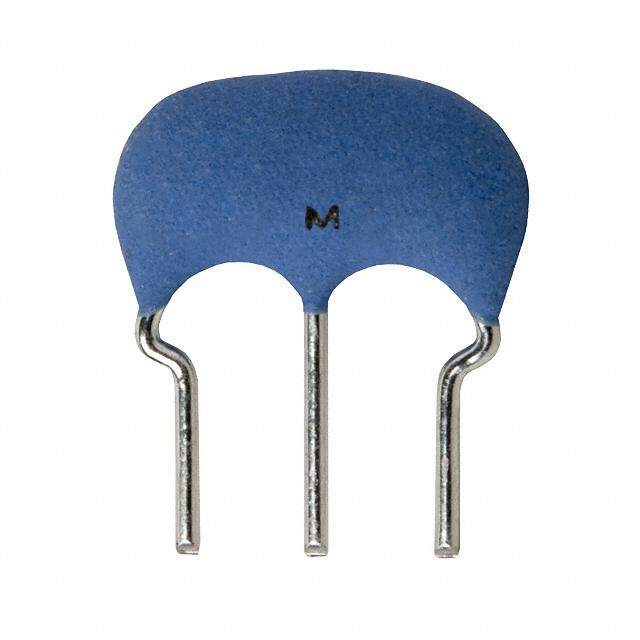
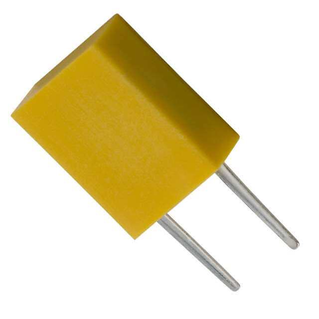
!Note (cid:129) Please read rating and !CAUTION (for storage, operating, rating, soldering, mounting and handling) in this catalog to prevent smoking and/or burning, etc. P16E.pdf (cid:129) This catalog has only typical specifications. Therefore, please approve our product specifications or transact the approval sheet for product specifications before ordering. Oct.1,2018 Ceramic Resonators (CERALOCKr) MHz Lead Type -Standard Frequency Tolerance for Consumer/Industrial Usage 8.0±1.0 3.0±1.0 MURATA's ceramic resonator, CERALOCKr with built-in lsouaitda cbalep acocimtopros,n heanst bfoere cnl owcikd eolsyc ailplaptloiersd ians a t hbero mado st *** 0.7 (Ref.) 5.5±0.5 range of microprocessors. 3 0. The CSTLS series can be used in the design of 5± 3. oscillation circuits not requiring external load 7.0 (Ref.) capacitors, enabling both high-density mounting and (3) (2) (1) 05 0. cost reduction. 8± 4 0. CSTLS_G ø : Frequency Marking Features 3.40-10.00MHz : Vender’s Code 2.5±0.2 2.5±0.2 ***: Weekly Date Code (in mm) 1. Oscillation circuits do not require external load capacitors. There is some variation in built-in capacitance values applicable to various IC. 5.5±1.0 T*1 2. Stable over a wide temperature range. * 3. Compact, lightweight and exhibit superior shock 0.5 5± resistance performance. 6. 4. Enable the design of oscillator circuits requiring no 3 adjustment. 5±0. 3. 5. Cost-effective and reliable availability (3) (2) (1) Applications T*1: 3.5±1.0 (16.00–32.99MHz) 3.0±1.0 (33.00–70.00MHz) CSTLS_X 05 : Frequency Marking 1. DTMF generators 16.00-70.00MHz 2.5±0.2 2.5±0.2 48±0. * : EIAJ Monthly Code 5 2. Clock oscillators for microcomputers ø0. (in mm) 3. Remote control units 4. Automated office equipment Frequency Initial Frequency Shift by Temperature Operating Part Number Frequency Tolerance Temperature Range (MHz) (%) (%) (°C) CSTLS_G 3.40 to 10.00 ±0.5 ±0.2 [-0.4% to +0.2%:Built-in Capacitance 47pF type] -20 to 80 CSTLS_X 16.00 to 70.00 ±0.5 ±0.2 -20 to 80 Irregular or stopped oscillation may occur under unmatched circuit conditions. Please check the actual conditions prior to use. The order quantity should be an integral multiple of the "Minimum Quantity" shown on the packaging page. Measuring Circuit of Oscillating Frequency 32-bit Microcomputer VDD To Frequency Counter Rf Rd (1) (3) C1 C2 (2) 17
!Note (cid:129) Please read rating and !CAUTION (for storage, operating, rating, soldering, mounting and handling) in this catalog to prevent smoking and/or burning, etc. P16E.pdf (cid:129) This catalog has only typical specifications. Therefore, please approve our product specifications or transact the approval sheet for product specifications before ordering. Oct.1,2018 Frequency Temperature Characteristics CSTLS_G CSTLS_X +0.50 0.3 0.2 %) %) ft ( +0.25 ft ( Oscillating Frequency Shi–0.205 –40 0 40 80Tempera1tu2r0e (°C) Oscillating Frequency Shi––0000....1012–50 –30 –10 10 30 50 70 90Temp1er1a0ture 1(°3C0) –0.3 –0.50 5 18
!Note (cid:129) Please read rating and !CAUTION (for storage, operating, rating, soldering, mounting and handling) in this catalog to prevent smoking and/or burning, etc. P16E.pdf (cid:129) This catalog has only typical specifications. Therefore, please approve our product specifications or transact the approval sheet for product specifications before ordering. Oct.1,2018 Notice for Consumer/Industrial Usage -MHz Chip Type Soldering and Mounting (CSTCR_G/CSTNR_GH5L, CSTNE_G/GH5L, CSTNE_V/VH3L Series) 1. Soldering (1) Reflow soldering Please mount the component on a circuit board by reflow soldering. Flow soldering is not acceptable. Recommendable Flux and Solder Please use rosin based flux, Flux not water soluble flux. Please use solder (Sn-3.0Ag-0.5Cu) under 260 Peak Solder the following conditions: Standard thickness C) 245 of soldering paste: 0.10 to 0.15mm. e (° 220 Heating atur 115800 (220°C min.) Recommendable Soldering Profile mper (1P5r0e -thoe 1a8ti0n°gC) Pre-heating 150 to 180°C 60 to 120s Te Gradual Cooling Heating 220°C min. 30 to 60s upper limit: 260°C 1s max. Peak Temperature lower limit: 245°C 5s max. 60 to 120s 30 to 60s Temperature shall be measured on the surface of component. (2) Soldering with Iron (4) Other If compelled to mount the component by using a Do not reuse components removed from a circuit board soldering iron, please do not directly touch the after soldering. component with the soldering iron. The component terminals or electrical characteristics may be damaged if (5) Conditions for Placement Machines excessive thermal stress is applied. The component is recommended with placement machines that employ optical placement capabilities. Recommendable Soldering with Iron The component may be damaged by excessive Heating of the soldering iron 350°C max. mechanical force. Please make sure that you have Watt 30W max. evaluated by using placement machines before going into Shape of the soldering iron ø3mm max. mass production. Do not use placement machines that Soldering Time 5s max. at one terminal utilize mechanical positioning. Please contact Murata for Solder Sn-3.0Ag-0.5Cu details beforehand. (3) Solder Volume Please make the solder volume less than the height of the substrate to avoid damage to the seal between the metal cap and the substrate. 2. Washing / Coating Conformal coating or washing of the component is not acceptable, because it is not hermetically sealed. Please contact us if you need a washable component. Continued on the following page. 19
!Note (cid:129) Please read rating and !CAUTION (for storage, operating, rating, soldering, mounting and handling) in this catalog to prevent smoking and/or burning, etc. P16E.pdf (cid:129) This catalog has only typical specifications. Therefore, please approve our product specifications or transact the approval sheet for product specifications before ordering. Oct.1,2018 Notice for Consumer/Industrial Usage -MHz Chip Type Continued from the preceding page. Storage and Operating Conditions 1. Product Storage Conditions (2) Please do not put the products directly on the Please store the products in a room where the floor without anything under them to avoid damp temperature/humidity is stable, and avoid and/or dusty places. places where there are large temperature (3) Please do not store the products in places changes. Please store the products under the such as: in a damp heated place, in a place where following conditions: direct sunlight comes in, in a place applying Temperature: -10 to +40°C vibrations. Humidity: 15 to 85% R.H. (4) Please use the products immediately after the 2. Expiration Date on Storage package is opened, because the characteristics Expiration date (shelf life) of the products is six may be reduced in quality, and/or be degraded in months after delivery under the conditions of a the solderability due to storage under poor sealed and unopened package. Please use the conditions. products within six months after delivery. If you (5) Please do not drop the products to avoid cracking store the products for a long time (more than six of ceramic elements. months), use carefully because the products may 4. Other be degraded in solderability and/or rusty. Conformal coating or washing of the component is not Please confirm solderability and characteristics acceptable because it is not hermetically sealed. for the products regularly. Please be sure to consult with our sales representatives 3. Notice on Product Storage or engineers whenever and prior to using the products. (1) Please do not store the products in a chemical atmosphere (Acids, Alkali, Bases, Organic gas, Sulfides and so on), because the characteristics may be reduced in quality, and/or be degraded in the solderability due to storage in a chemical atmosphere. Rating The component may be damaged if excessive mechanical stress is applied. Handling "CERALOCK" may stop oscillating or oscillate irregularly under improper circuit conditions. 20
!Note (cid:129) Please read rating and !CAUTION (for storage, operating, rating, soldering, mounting and handling) in this catalog to prevent smoking and/or burning, etc. P16E.pdf (cid:129) This catalog has only typical specifications. Therefore, please approve our product specifications or transact the approval sheet for product specifications before ordering. Oct.1,2018 Notice for Consumer/Industrial Usage -MHz Lead Type Soldering and Mounting (CSTLS_G, CSTLS_X Series) The component cannot withstand washing. Please do not apply excessive mechanical stress to the component and lead terminals during soldering. Storage and Operating Conditions 1. Product Storage Conditions (2) Please do not put the products directly on the Please store the products in a room where the floor without anything under them to avoid damp temperature/humidity is stable, and avoid and/or dusty places. places where there are large temperature (3) Please do not store the products in places changes. Please store the products under the such as: in a damp heated place, in a place where following conditions: direct sunlight comes in, in a place applying Temperature: -10 to +40°C vibrations. Humidity: 15 to 85% R.H. (4) Please use the products immediately after the 2. Expiration Date on Storage package is opened, because the characteristics Expiration date (shelf life) of the products is six may be reduced in quality, and/or be degraded in months after delivery under the conditions of a the solderability due to storage under poor sealed and unopened package. Please use the conditions. products within six months after delivery. If you (5) Please do not drop the products to avoid cracking store the products for a long time (more than six of ceramic elements. months), use carefully because the products may 4. Other be degraded in solderability and/or rusty. Conformal coating or washing of the component is not Please confirm solderability and characteristics acceptable because it is not hermetically sealed. for the products regularly. Please be sure to consult with our sales representatives 3. Notice on Product Storage or engineers whenever and prior to using the products. (1) Please do not store the products in a chemical atmosphere (Acids, Alkali, Bases, Organic gas, Sulfides and so on), because the characteristics may be reduced in quality, and/or be degraded in the solderability due to storage in a chemical atmosphere. Rating The component may be damaged if excessive mechanical stress is applied. Handling "CERALOCK" may stop oscillating or oscillate irregularly under improper circuit conditions. 21
!Note (cid:129) Please read rating and !CAUTION (for storage, operating, rating, soldering, mounting and handling) in this catalog to prevent smoking and/or burning, etc. P16E.pdf (cid:129) This catalog has only typical specifications. Therefore, please approve our product specifications or transact the approval sheet for product specifications before ordering. Oct.1,2018 Packaging for Consumer/Industrial Usage -MHz Chip Type Minimum Quantity Part Number Plastic Tape ø180mm Plastic Tape ø330mm Bulk Reel Dimensions CSTCR_G 3,000 9,000 500 a CSTNR_GH5L 3,000 9,000 500 a CSTNE_G 3,000 9,000 500 b CSTNE_GH5L 3,000 9,000 500 b CSTNE_V 3,000 9,000 500 b CSTNE_VH3L 3,000 9,000 500 b The order quantity should be an integral multiple of the "Minimum Quantity" shown above. (pcs.) Dimensions of Reel a b Trailer Leader Trailer Leader 160-190 Cover Film 160-190 Cover Film Empty Components Empty EmptyComponents Empty 160 min. 160 min. 400-560 400-560 00 )–1.5 00 )–1.5 8 8 1 1 (ø ø13.0±0.2 2.0±0.5 (ø ø13.0±0.2 2.0±0.5 13.0+01.0 9.0+–10.0 17.0±1.0 13.0±1.0 (in mm) Dimensions of Taping CSTNR_GH5L CSTNE_GH5L 4.0±0.1 2.0±0.05 ø1.5+-00.1 1.75±0.1 4.0±0.1 2.0±0.05 ø1.5 +-00..01 1.75±0.1 5 5 (9.5) (3)(2)(1) 4.7±0.1 5.5±0.0 12.0±0.2 (5.2) (3)(2)(1) +0.103.40 -0.05 3.5±0.0 8.0±0.2 4.0±0.1 ø1.5±0.1 4.0±0.1 ø1.0 +-00..02 +0.10 Cover film peel strength force 0.1 to 0.7N 2.2±0.1 Cover film peel strength force 0.1 to 0.7N 1.50 -0.05 Cover film peel speed 31000°mm/min. Cover Film (5°) 0.25±0.05 1.25±0.1 (1.85 max.) Cover film peel sp1e0ed° 300mm/min. Cover Film (7˚) 0.25±0.050.90±0.10 (1.30 max.) Direction of Feed (in mm) Direction of Feed (in mm) CSTNE_VH3L 4.0±0.1Di2m.0e±n0s.i0on5s of Carrierø T1a.5p+-e00..10 75±0.1 1. 5 0 (5.2) (2)(3)(1) +0.103.40-0.05 3.5±0. 8.0±0.2 4.0±0.1 ø1.0+-00..20 +0.10 Cover film peel strength force 0.1 to 0.7N 1.50-0.05 Cover film peel speed 300mm/m10in°. Cover Film (5°) 0.25±0.05 1.10±0.10 1.40 max.) ( Direction of Feed (in mm) Continued on the following page. 22
!Note (cid:129) Please read rating and !CAUTION (for storage, operating, rating, soldering, mounting and handling) in this catalog to prevent smoking and/or burning, etc. P16E.pdf (cid:129) This catalog has only typical specifications. Therefore, please approve our product specifications or transact the approval sheet for product specifications before ordering. Oct.1,2018 Packaging for Consumer/Industrial Usage -MHz Chip Type Continued from the preceding page. Dimensions of Taping CSTCR_G CSTNE_G 4.0±0.1 2.0±0.05 ø1.5+-00.1 1.75±0.1 4.0±0.1 2.0±0.05 ø1.5 +-00..01 1.75±0.1 5 5 (9.5) (3)(2)(1) 4.7±0.1 5.5±0.0 12.0±0.2 (5.2) (3)(2)(1) +0.103.40 -0.05 3.5±0.0 8.0±0.2 4.0±0.1 ø1.5+-00.1 4.0±0.1 ø1.0 +-00..02 +0.10 Cover film peel strength force 0.1 to 0.7N 2.2±0.1 Cover film peel strength force 0.1 to 0.7N 1.50 -0.05 Cover film peel speed 31000°mm/min.Cover Film (3°) 0.3±0.05 1.25±0.05 (1.85 max.) Cover film peel sp1e0ed° 300mm/min. Cover Film (7˚) 0.25±0.050.90±0.10 (1.30 max.) Direction of Feed (in mm) Direction of Feed (in mm) CSTNE_V 4.0±0.1Di2m.0e±n0s.i0on5s of Carrierø T1a.5p+-e00..10 75±0.1 1. 5 0 (5.2) (2)(3)(1) +0.103.40-0.05 3.5±0. 8.0±0.2 4.0±0.1 ø1.0+-00..20 +0.10 Cover film peel strength force 0.1 to 0.7N 1.50-0.05 Cover film peel speed 300mm/m10in°. Cover Film (5°) 0.25±0.05 1.10±0.10 1.40 max.) ( Direction of Feed (in mm) 23
!Note (cid:129) Please read rating and !CAUTION (for storage, operating, rating, soldering, mounting and handling) in this catalog to prevent smoking and/or burning, etc. P16E.pdf (cid:129) This catalog has only typical specifications. Therefore, please approve our product specifications or transact the approval sheet for product specifications before ordering. Oct.1,2018 Packaging for Consumer/Industrial Usage -MHz Lead Type Minimum Quantity Part Number Ammo Pack Bulk CSTLS_G (3.40 to 10.0MHz) 2,000 500 CSTLS_X (16.00 to 70.00MHz) 2,000 500 The order quantity should be an integral multiple of the "Minimum Quantity" shown above. (pcs.) Tape Dimensions of CSTLS_G P2 P dh dh D dS M*** A M*** d 2 W 1 H 0 H L1 W0 W1 W D0 P1 F1 F2 P0 Direction of Feed t Item Code Dimensions Tolerance Remarks Width of diameter D 8.0 ±1.0 Height of resonator A 5.5 ±0.5 Dimensions of terminal d ø0.48 ±0.05 Lead length under the hold down tape L1 5.0 min. – Pitch of component P 12.7 ±0.5 Tolerance for Pitches 10xP0=127±1 Pitch of sprocket hole P0 12.7 ±0.2 Length from sprocket hole center to lead P1 3.85 ±0.5 Length from sprocket hole center to P2 6.35 ±0.5 component center Lead spacing (I) F1 2.5 ±0.2 Lead spacing (II) F2 2.5 ±0.2 Slant forward or backward dh 0 ±1.0 1mm max. Width of carrier tape W 18.0 ±0.5 Width of hold down tape W0 6.0 min. – Hold down tape does not exceed the carrier tape. Position of sprocket hole W1 9.0 ±0.5 +0.5 Gap of hold down tape and carrier tape W2 0 −0 Distance between the center of H0 18.0 ±0.5 sprocket hole and lead stopper Total height of resonator H1 23.5 ±1.0 Diameter of sprocket hole D0 ø4.0 ±0.2 Total tape thickness t 0.6 ±0.2 Body tilt dS 0 ±1.0 (in mm) Continued on the following page. 24
!Note (cid:129) Please read rating and !CAUTION (for storage, operating, rating, soldering, mounting and handling) in this catalog to prevent smoking and/or burning, etc. P16E.pdf (cid:129) This catalog has only typical specifications. Therefore, please approve our product specifications or transact the approval sheet for product specifications before ordering. Oct.1,2018 Packaging for Consumer/Industrial Usage -MHz Lead Type Continued from the preceding page. Tape Dimensions of CSTLS_X P2 P dh dh D dS A d W2 1 H 0 L1 W0 W1 H W D0 P1 F1 F2 Direction of Feed P0 t Item Code Dimensions Tolerance Remarks Width of diameter D 5.5 ±1.0 Height of resonator A 6.5 ±0.5 Dimensions of terminal d ø0.48 ±0.05 Lead length under the hold down tape L1 5.0 min. – Pitch of component P 12.7 ±0.5 Tolerance for Pitches 10xP0=127±1 Pitch of sprocket hole P0 12.7 ±0.2 Length from sprocket hole center to lead P1 3.85 ±0.5 Length from sprocket hole center to P2 6.35 ±0.5 component center Lead spacing (I) F1 2.5 ±0.2 Lead spacing (II) F2 2.5 ±0.2 Slant forward or backward dh 0 ±1.0 1mm max. Width of carrier tape W 18.0 ±0.5 Width of hold down tape W0 6.0 min. – Hold down tape does not exceed the carrier tape. Position of sprocket hole W1 9.0 ±0.5 +0.5 Gap of hold down tape and carrier tape W2 0 −0.0 Distance between the center of H0 18.0 ±0.5 sprocket hole and lead stopper Total height of resonator H1 24.5 ±1.0 Diameter of sprocket hole D0 ø4.0 ±0.2 Total tape thickness t 0.6 ±0.2 Body tilt dS 0 ±1.0 (in mm) 25
P16E.pdf Oct.1,2018 Cat. No. P16E-27 Global Locations For details please visit www.murata.com Note 1 Export Control 2 Please contact our sales representatives or 3 Product specifi cations in this catalog are as of product engineers before using the products in October 2018. They are subject to change or For customers outside Japan: this catalog for the applications listed below, our products in it may be discontinued without No Murata products should be used or which require especially high reliability for the advance notice. Please check with our sales sold, through any channels, for use in the prevention of defects which might directly representatives or product engineers before design, development, production, utilization, damage a third party’s life, body or property, or ordering. If there are any questions, please contact maintenance or operation of, or otherwise when one of our products is intended for use our sales representatives or product engineers. contribution to (1) any weapons (Weapons of in applications other than those specified in Mass Destruction [nuclear, chemical or biological this catalog. 4 Please read rating and CAUTION (for storage, weapons or missiles] or conventional weapons) operating, rating, soldering, mounting and or (2) goods or systems specially designed or 1 Aircraft equipment handling) in this catalog to prevent smoking intended for military end-use or utilization by 2 Aerospace equipment and/or burning, etc. military end-users. 3 Undersea equipment 5 This catalog has only typical specifi cations. For customers in Japan: Therefore, please approve our product 4 Power plant equipment specifi cations or transact the approval sheet For products which are controlled items subject for product specifi cations before ordering. to the “Foreign Exchange and Foreign Trade Law” 5 Medical equipment of Japan, the export license specifi ed by the law 6 Please note that unless otherwise specifi ed, we is required for export. 6 Transportation equipment (vehicles, trains, shall assume no responsibility whatsoever for any ships, etc.) confl ict or dispute that may occur in connection 7 Traffi c signal equipment with the eff ect of our and/or a third party’s intellectual property rights and other related 8 Disaster prevention / crime prevention rights in consideration of your use of our products equipment and/or information described or contained in our catalogs. In this connection, no representation 9 Data-processing equipment shall be made to the eff ect that any third parties are authorized to use the rights mentioned above 10 Application of similar complexity and/or under licenses without our consent. reliability requirements to the applications listed above 7 No ozone depleting substances (ODS) under the Montreal Protocol are used in our manufacturing process. Murata Manufacturing Co., Ltd. www.murata.com