 Datasheet下载
- 型号: CP1A-12V
- 制造商: Panasonic Corporation
- 库位|库存: xxxx|xxxx
- 要求:
| 数量阶梯 | 香港交货 | 国内含税 |
| +xxxx | $xxxx | ¥xxxx |
查看当月历史价格
查看今年历史价格
CP1A-12V产品简介:
ICGOO电子元器件商城为您提供CP1A-12V由Panasonic Corporation设计生产,在icgoo商城现货销售,并且可以通过原厂、代理商等渠道进行代购。 CP1A-12V价格参考¥13.13-¥13.13。Panasonic CorporationCP1A-12V封装/规格:汽车继电器, 。您可以下载CP1A-12V参考资料、Datasheet数据手册功能说明书,资料中有CP1A-12V 详细功能的应用电路图电压和使用方法及教程。
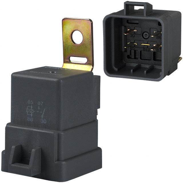
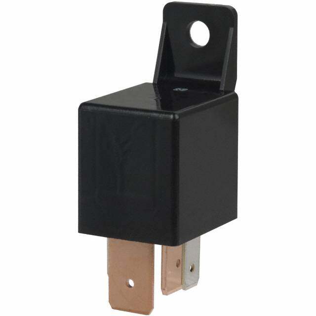
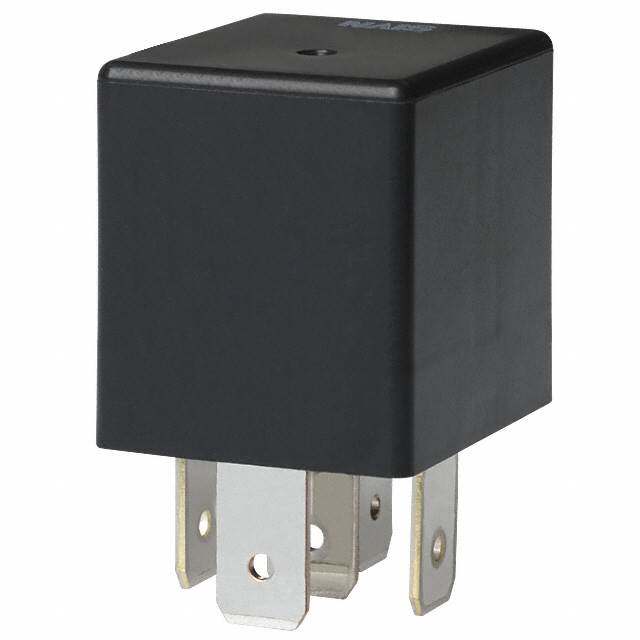
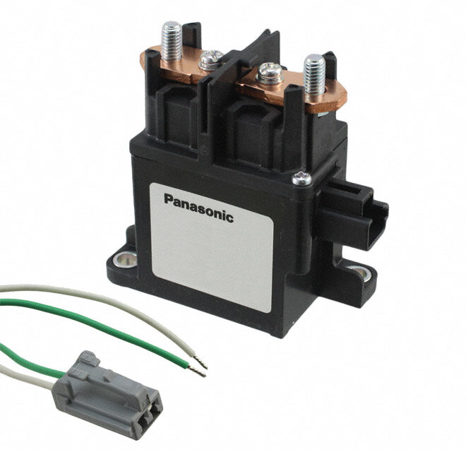
Panasonic Electric Works(现为Panasonic Industrial Devices)生产的CP1A-12V汽车继电器是一种小型信号继电器,广泛应用于汽车电子系统中。以下是该型号继电器的主要应用场景:

 1. 汽车控制系统
   - 电源管理:用于控制汽车中的低功率电路,例如车灯、雨刷器、电动窗等设备的开关。
   - 传感器信号切换:在汽车传感器网络中,用于切换不同信号路径,确保信号传输的准确性和稳定性。

 2. 车载娱乐系统
   - 在车载音响和导航系统中,CP1A-12V可用于控制音频信号的切换或电源分配,支持多音源输入(如CD、蓝牙、USB)之间的切换。

 3. 安全与报警系统
   - 防盗报警:继电器可用于控制防盗系统的警报器启动或关闭。
   - 倒车雷达:用于控制倒车雷达传感器的电源供应,当车辆挂入倒档时自动激活。

 4. 发动机管理系统
   - 在发动机控制单元(ECU)中,CP1A-12V可以用于信号隔离或放大,帮助实现对燃油喷射、点火系统等的精确控制。

 5. 电动车窗与座椅调节
   - 用于电动车窗、后视镜调节、座椅加热等功能的电路控制,确保这些功能在低电流条件下可靠运行。

 6. LED照明系统
   - 在现代汽车的LED大灯、日间行车灯或尾灯中,CP1A-12V可作为信号切换或负载控制的组件,确保灯光系统的稳定运行。

 7. 新能源汽车应用
   - 在混合动力或纯电动汽车中,该继电器可用于辅助系统的信号控制,例如电池管理系统(BMS)中的低功耗信号切换。

 特性优势
- 小尺寸设计:适合空间有限的汽车环境。
- 高可靠性:能够在振动和温度变化较大的汽车环境中长期稳定工作。
- 低功耗:适用于需要节能的汽车电子系统。

总结来说,CP1A-12V继电器凭借其紧凑的设计和可靠的性能,成为汽车电子系统中不可或缺的关键元件,适用于多种场景下的信号切换和电路控制。
| 参数 | 数值 |
| 产品目录 | |
| 描述 | RELAY AUTOMOTIVE SPST 20A 12V车用继电器 20A 12VDC 1 FORM A PCB |
| 产品分类 | |
| 品牌 | Panasonic Electric Works |
| 产品手册 | |
| 产品图片 |
|
| rohs | RoHS 合规性豁免无铅 / 符合限制有害物质指令(RoHS)规范要求 |
| 产品系列 | 车用继电器,Panasonic Industrial Devices CP1A-12VCP |
| mouser_ship_limit | 该产品可能需要其他文件才能进口到中国。 |
| 数据手册 | |
| 产品型号 | CP1A-12V |
| 产品目录绘图 |
|
| 产品目录页面 | |
| 产品种类 | 车用继电器 |
| 关闭电压(最小值) | 1 VDC |
| 其它名称 | 255-1940 |
| 其它有关文件 | |
| 功耗 | 640 mW |
| 包装 | 管件 |
| 商标 | Panasonic Industrial Devices |
| 安装类型 | 通孔 |
| 安装风格 | Through Hole |
| 导通电压(最大值) | 7.2 VDC |
| 封装 | Bulk |
| 工作时间 | 10ms |
| 工作温度 | -40°C ~ 85°C |
| 工厂包装数量 | 40 |
| 开关电压 | 14VDC -标称 |
| 标准包装 | 40 |
| 特性 | 密封式 - 全部 |
| 端子类型 | PC 引脚 |
| 类型 | Automotive Relays |
| 线圈功率 | 640 mW |
| 线圈电压 | 12VDC |
| 线圈电流 | 53.3mA |
| 线圈电阻 | 225 欧姆 |
| 线圈端接 | Solder Terminal |
| 线圈类型 | 无锁存 |
| 继电器类型 | 自动 |
| 触头外形 | SPST-NO(1 A 型) |
| 触头材料 | 银合金,无镉 |
| 触点形式 | 1 Form A (SPST-NO) |
| 触点材料 | Silver Alloy |
| 触点端接 | Solder Terminal |
| 释放时间 | 10ms |
| 额定接触(电流) | 20A |


- 商务部:美国ITC正式对集成电路等产品启动337调查
- 曝三星4nm工艺存在良率问题 高通将骁龙8 Gen1或转产台积电
- 太阳诱电将投资9.5亿元在常州建新厂生产MLCC 预计2023年完工
- 英特尔发布欧洲新工厂建设计划 深化IDM 2.0 战略
- 台积电先进制程称霸业界 有大客户加持明年业绩稳了
- 达到5530亿美元!SIA预计今年全球半导体销售额将创下新高
- 英特尔拟将自动驾驶子公司Mobileye上市 估值或超500亿美元
- 三星加码芯片和SET,合并消费电子和移动部门,撤换高东真等 CEO
- 三星电子宣布重大人事变动 还合并消费电子和移动部门
- 海关总署:前11个月进口集成电路产品价值2.52万亿元 增长14.8%

PDF Datasheet 数据手册内容提取
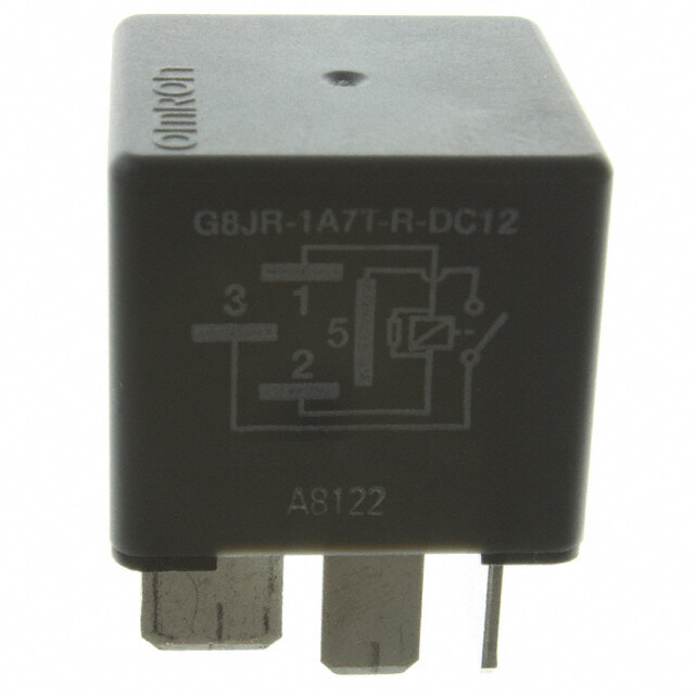
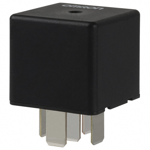
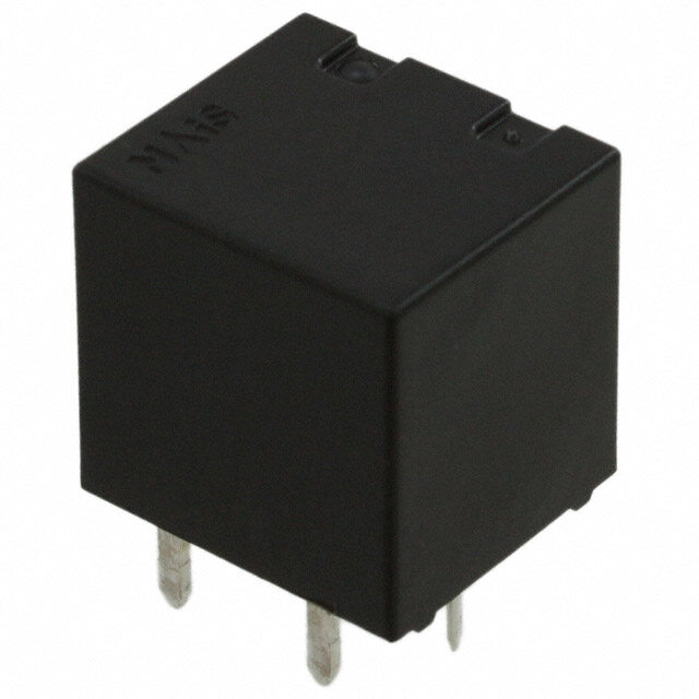
CP Compact flat size CP RELAYS PC board relay for automotive FEATURES • Compact flat type • Sealed construction Flat size enables it to be built-in switch Sealed construction suitable for harsh units. environments <Height> • “PC board terminal” and “Surface PC board terminal type: mount terminal” types available 9.5 mm .374 inch SMD automatic mounting is possible for Surface-mount terminal type: surface mount terminal types because 10.5mm .413inch tape and reel packaging is used. • High capacity • Model available for wiper load. CP Relay provides low profile spacesaving advantages while offering TYPICAL APPLICATIONS high continuous current of 25A (1 hour). • Simple footprint pattern enables For automotive system ease of PC board layout Power windows, Auto door lock, Power Arrangement of coil and contact sunroof, Memory seat, Wiper, Defogger, terminals designed to withstand large etc. capacity which ensures leeway and facilitates PC board design. ORDERING INFORMATION CP Contact arrangement 1: 1 Form C 1a: 1 Form A 1W:1 Form C for wiper load Mounting classification Nil: PC board terminal/wiper load SA:Surface-mount terminal*1 Coil voltage (DC) 12 V Packing style*2 Nil:Tube packing X: Tape and reel packing (picked from the NC terminal side) Z: Tape and reel packing (picked from the coil terminal side) TYPES 1. PC board terminal type Contact arrangement Coil voltage Part No. 1 Form A CP1a-12V 1 Form C 12V DC CP1-12V 1 Form C for wiper load CP1W-12V Standard packing; Carton (tube): 40 pcs.; Case: 1,000 pcs. 2. Surface mount terminal type Contact arrangement Coil voltage Part No. CP1SA-12V-X 1 Form C 12V DC CP1SA-12V-Z Standard packing; Carton (tape and reel): 300 pcs.; Case: 900 pcs. Notes: *1.Surface-mount terminal type is available only for 1 form C contact arrangement. *2.Surface mount terminal type is only supplied in tape and reel packaging. Tube packaging is only available for PC board type. Tape and reel packing symbol “-z” or “-x” are not marked on the relay. ds_61207_en_cp: 010113J 1
CP RATING 1. Coil data Nominal operating Nominal operating Nominal coil Pick-up voltage Drop-out voltage Coil resistance Usable voltage range current power voltage (at 20C 68F) (at 20C 68F) [10%] (at 20C 68F) (at 85C 185F) [10%] (at 20C 68F) (at 20C 68F) Max. 7.2V DC Min. 1.0V DC 12V DC 53.3 mA 225 640 mW 10 to 16V DC (Initial) (Initial) Note: Other pick-up voltage types are also available. Please contact us for details. 2. Specifications 1) Standard CP relay Characteristics Item Specifications Arrangement 1 Form A 1 Form C Contact Initial contact resistance (Initial) N.O.: Typ6m, N.C.: Typ8m (By voltage drop 6V DC 1A) Contact material Ag alloy (Cadmium free) Nominal switching capacity (resistive load) 20A 14V DC N.O.: 20A 14V DC, N.C.: 10A 14V DC N.O.: 40A for 2 minutes, 30A for 1 hour (at 20C 68F) Max. carrying current (12V DC initial)*3 Rating 35A for 2 minutes, 25A for 1 hour (at 85C 185F) Nominal operating power 640 mW Min. switching capacity (resistive load)*1 1A 12V DC Insulation resistance (Initial) Min. 100 M (at 500V DC) Breakdown voltage Between open contacts 500 Vrms for 1 min. (Detection current: 10mA) Electrical (Initial) Between contacts and coil 500 Vrms for 1 min. (Detection current: 10mA) characteristics Operate time (at nominal voltage) Max. 10ms (at 20C 68F, excluding contact bounce time) (Initial) Release time (at nominal voltage) Max. 10ms (at 20C 68F, excluding contact bounce time) (Initial) Functional Min. 100 m/s2 {10G} (Half-wave pulse of sine wave: 11ms; detection: 10s) Shock resistance Destructive Min. 1,000 m/s2 {100G} (Half-wave pulse of sine wave: 6ms) Mechanical characteristics Functional 10 Hz to 100 Hz, Min. 44.1 m/s2 {4.5G} (Detection time: 10s) Vibration resistance 10 Hz to 500 Hz, Min. 44.1 m/s2 {4.5G} Destructive Time of vibration for each direction; X, Y direction: 2 hours, Z direction: 4 hours Mechanical Min. 107 (at 120 cpm) <Resistive load> Min. 105 (At nominal switching capacity, operating frequency: 1s ON, 9s OFF) Expected life <Motor load*> Electrical*4. Min. 2×10⁵ (N.O. side, Inrush 25A, steady 5A at 14V DC) Min. 105 (N.O. side, 20A 14V DC at motor lock) Min. 2×10⁵ (N.C. side, 20A 14V DC at brake current) (Operating frequency: 0.5s ON, 9.5s OFF) Ambient temp: –40C to +85C –40F to +185F Conditions for operation, transport and storage*2 Conditions Humidity: 5% R.H. to 85% R.H. (Not freezing and condensing at low temperature) Max. operating speed 6 cpm (at rated load) Mass Approx. 4g .14 oz Notes: *1.This value can change due to the switching frequency, environmental conditions, and desired reliability level, therefore it is recommended to check this with the actual load. *2.Refer to “6. Usage, Storage and Transport Conditions“ in AMBIENT ENVIRONMENT section in Relay Technical Information. Please inquire if you will be using the relay in a high temperature atmosphere (110C 230F). *3.Depends on connection conditions. Also, this does not guarantee repeated switching. We recommend that you confirm operation under actual conditions. *4.Motor load does not apply to wiper load applications. 2) For wiper load (CP1W-12V) Anything outside of that given below complies with standard CP relays. Characteristics Item Specifications Rating Max. carrying current (12V DC initial) N.O.: 25A for 1 minutes, 15A for 1 hour (at 20C 68F) <Wiper motor load (L = Approx. 1mH)> N.O. side: Min. 5105 (Inrush 25A, steady 6A at 14V DC) Expected life Electrical N.C. side: Min. 5105 (12A 14V DC at brake current) (Operating frequency: 1s ON, 9s OFF) Note:*1. Depends on connection conditions. Also, this does not guarantee repeated switching. We recommend that you confirm operation under actual conditions. 2 ds_61207_en_cp: 010113J
CP REFERENCE DATA 1.-(1) Coil temperature rise (at room 1.-(2) Coil temperature rise 2. Max. switching capability temperature) Sample: CP1-12V, 6pcs (Resistive load, initial) Sample: CP1-12V, 3pcs Point measured: Inside the coil Point measured: Inside the coil Contact carrying current, 5A, 10A, 15A, 20A Contact carrying current, 5A, 10A, 15A, 20A Resistance method, ambient temperature 85C 185F Resistance method, ambient temperature 26C 79F 120 100 60 (N.O. side: room temperature) 20A °Temperature rise, C108640000 25110A05AAA °Temperature rise, C 864000 11550AAA witching voltage, VDC 543000 S 20 20 20 10 0 12 14 16 0 12 14 16 00 10 20 30 40 50 Coil applied voltage, V Coil applied voltage, V Switching current, A 3. Ambient temperature and operating voltage 4. Distribution of pick-up and drop-out voltage 5. Distribution of operate time range Sample: CP1-12V, 100pcs Sample: CP1-12V, 100pcs Ambient temperature: 20C 68F Ambient temperature: 20C 68F 30 70 100 Pick-up voltage DC 25 60 Drop-out voltage 90 V 80 plied voltage, 1250 Operating voltage range Quantity, n 4500 Quantity, n 567000 Coil ap 10 3200 3400 20 5 10 Pick-up voltage 10 (cold start) 0 0 0 −40−20 0 20 40 60 80 100120 1.52.02.53.03.54.04.55.05.56.06.57.07.58.0 1.52.0 2.5 3.03.5 4.04.55.0 5.5 6.06.5 Ambient temperature, °C Voltage, V Time, ms 6. Distribution of release time 7.-(1) Electrical life test (at resistive load) Sample: CP1-12V, 100pcs Sample: CP1-12V Ambient temperature: 20C 68F Quantity: n = 4 (N.C. = 2, N.O. = 2) * Without diode Load: Resistive load (N.C. side: 10A 14V DC, N.O. side: 20A 14V DC) Operating frequency: ON 1s, OFF 9s Ambient temperature: Room temperature * Without diode 100 10 V Contact welding: 0 times 90 e, Miscontact: 0 times g 80 olta 8 Quantity, n 567000 d drop-out v 6 Pick-up voltage XMMainx.. n 40 p a 4 3200 Pick-u Drop-out voltage 2 Max. 10 X Min. 0 0 0.51.01.5 2 2.5 3 3.5 4 4.55.0 0 0 5 10 Time, ms No. of operations, × 104 ds_61207_en_cp: 010113J 3
CP 7.-(2) Electrical life test for wiper load Change of pick-up and drop-out voltage Change of contact resistance (motor free) Sample: CP1W-12V Quantity: n = 5 10 50 LLooaadd:: NN..CO.. ssiiddee:: BInrraukseh c2u5rAre,n stt e1a2dAy 1 64AV 1D4CV DC ge, V 8 Ω NN..CO.. ssiiddee OACmiprceburiaeittnint gte fmrepqeureantucrye: :O RNo o1ms, tOemFFp e9rsature nd drop-out volta 6795 Pick-up voltage MMxainx.. act resistance, m 3400 Max. p a 4 ont 20 x u C Max. Pick- 3 Drop-out voltage Mxin. M 2 Max. 10 Min. x 1 Min. 0 0 0 10 25 50 0 10 25 50 No. of operations, × 104 No. of operations, × 104 DIMENSIONS (mm inch) Download CCAADD DDaattaa from our Web site. 1. PC board terminal type CAD Data External dimensions PC board pattern Schematic (Bottom view) (Bottom view) 14.0 13.0 .551 .512 1 Form A 1 Form A .397.54 Max. 22××.00.395+00+. 1 .0 0 0 d 4 iad.ia. 0.4 1.0 .016 .039 22××.20.709+00+. 1 .0 0 0 d 4 iad.ia. NO COM 3.5 A* .138 1.5 4.5 COIL 0.4 1.0 0.4 .059 0.3 .177 .016 .039 .016 .012 .519.07 1.7 Pre-soldering 22××.10.351+00+. 1 .0 0 0 d 4 iad.i ah. ohleole .263.06 2.0.079(R) .067 10.7 .421 5.4 1 Form C 1 Form C .213 .10.559 .62.036 .159.07 33××330.××0..2390.5+7000+. 91 +.0 0 00 0 +d. 1 4 .0 0 i 0 dad 4 i.iada.i.a. NC NO .263.06 2.0.079 5.2.413 COM 10.7 .421 COIL Dimension: Tolerance 4.5 .177 Max. 1mm .039 inch: 0.1 .004 1 to 3mm .039 to .118 inch:0.2 .008 22××.10.531+00+. 1 .0 0 0 d 4 iad.i ah. ohleole .26.306 2.0.079(R) Min. 3mm .118 inch: 0.3 .012 10.7 .421 * Dimensions (thickness and width) of terminal specified in this catalog is measured before pre-soldering. Intervals between terminals is measured at A surface level. 2. Surface mount terminal type CAD Data External dimensions Recommendable mounting pad Schematic (Top view) (Top view) 1.401.53.0.03.9145.681 .0P0.14re6-solde.00r.i14n6g .00.132 4.2 .263.06 NC .165 NO 11..5555 .0319 11..4455 1.0.663 0.1.10.559 1.0.351 .1435..480 2.0.079.029.582.5 2.0.079 COIL COM Sealed by 5.0 1.7 .173 .098 epoxy resin .197 .067 4.8 .189 5.4 4.8 4.7 4.0 4.8 .213 .189 .185 .157 .189 1.5 .059 6.0 .236 6.0 2 .236 .079 10.7 .421 Dimension: Tolerance Max. 1mm .039 inch: 0.1 .004 1 to 3mm .039 to .118 inch:0.2 .008 Min. 3mm .118 inch: 0.3 .012 4 ds_61207_en_cp: 010113J
CP NOTES 1. Mounting and cleaning conditions 2. Storage condition after opening a for SMT type relays moisture-prevention package 1) Recommended reflow condition is: 1) After opening a moisture-prevention • Reflow-soldering temperature profile package, use the item as soon as condition (IRS method) possible (within 3 days under an environment of Max. 30C 86F, Max. T3 70% RH). T2 2) If products are not used within 4 days after opening a moisture-prevention T1 package, store them in a humidity- controlled desiccator or in a storage bag with silica gel. t1 t2 T1 = 150 to 180°C302 to 356°F T2 = 230°C446°For more T3 = Less than 260°C500°F t1 = 60 to 120 sec. t2 = Less than 40 sec. *1 • Cautions for mounting operations Temperature profile indicates the temperature of the soldered part (*1) of terminals on the surface of a circuit board. The exterior temperature of a relay may be extremely high depending on the component density on the board or the heating method of the reflow oven or circuit board type. Sufficient verification under actual processing conditions is required. 2) Avoid cleaning (ultrasonic cleaning, boiling cleaning, etc.) and coating in order to prevent negative impacts on relay characteristics. For Cautions for Use, see Relay Technical Information. ds_61207_en_cp: 010113J 5