
 Datasheet下载
- 型号: CMF5013R300FHEB
- 制造商: Vishay
- 库位|库存: xxxx|xxxx
- 要求:
| 数量阶梯 | 香港交货 | 国内含税 |
| +xxxx | $xxxx | ¥xxxx |
查看当月历史价格
查看今年历史价格
CMF5013R300FHEB产品简介:
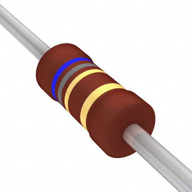
ICGOO电子元器件商城为您提供CMF5013R300FHEB由Vishay设计生产,在icgoo商城现货销售,并且可以通过原厂、代理商等渠道进行代购。 CMF5013R300FHEB价格参考。VishayCMF5013R300FHEB封装/规格:通孔电阻器, 13.3 Ohms ±1% 0.25W, 1/4W Through Hole Resistor Axial Flame Retardant Coating, Moisture Resistant, Safety Metal Film。您可以下载CMF5013R300FHEB参考资料、Datasheet数据手册功能说明书,资料中有CMF5013R300FHEB 详细功能的应用电路图电压和使用方法及教程。
Vishay Dale 型号为 CMF5013R300FHEB 的通孔电阻器属于 CMF(碳膜/金属膜)系列,具有高精度、低温度系数和良好的长期稳定性。该型号阻值为13.3Ω,功率为0.5W,精度±1%,采用轴向引线封装,适用于对稳定性和可靠性要求较高的电路。

其典型应用场景包括:工业控制设备中的精密信号调节与反馈电路;测试与测量仪器,如万用表、示波器等,用于分压、限流或校准电路;电源管理系统中作为采样电阻,监测电流或电压变化;通信设备中用于阻抗匹配和信号调理;以及医疗电子设备、航空航天电子模块等高可靠性领域。

由于该电阻具备优良的耐湿性、抗氧化性和长期负载稳定性,适合在恶劣环境或长时间连续运行的系统中使用。此外,其符合RoHS标准,支持无铅焊接工艺,适用于现代环保型电子产品制造。总之,CMF5013R300FHEB 广泛应用于需要高稳定性和可靠性的精密模拟电路中。
| 参数 | 数值 |
| 产品目录 | |
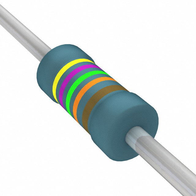
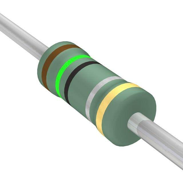
| 描述 | RES 13.3 OHM 1/4W 1% AXIAL |
| 产品分类 | |
| 品牌 | Vishay Dale |
| 数据手册 | |
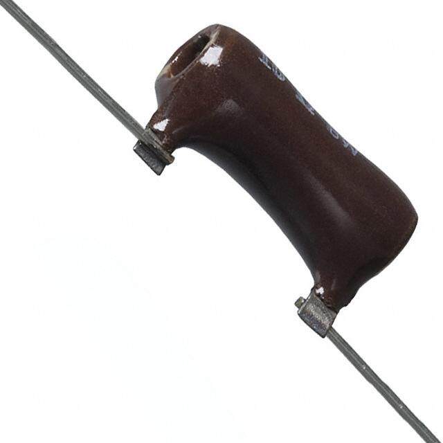
| 产品图片 |
|
| 产品型号 | CMF5013R300FHEB |
| rohs | 无铅 / 符合限制有害物质指令(RoHS)规范要求 |
| 产品系列 | CMF |
| 产品目录绘图 |
|
| 产品目录页面 | |
| 供应商器件封装 | 轴向 |
| 其它名称 | CMF13.3QFCT |
| 功率(W) | 0.25W,1/4W |
| 包装 | 剪切带 (CT) |
| 大小/尺寸 | 0.065" 直径 x 0.150" 长(1.65mm x 3.81mm) |
| 容差 | ±1% |
| 封装/外壳 | 轴向 |
| 成分 | 金属薄膜 |
| 标准包装 | 1 |
| 温度系数 | ±50ppm/°C |
| 特性 | 阻燃涂层,防潮 |
| 电阻(Ω) | 13.3 |
| 端子数 | 2 |
| 高度 | - |


- 商务部:美国ITC正式对集成电路等产品启动337调查
- 曝三星4nm工艺存在良率问题 高通将骁龙8 Gen1或转产台积电
- 太阳诱电将投资9.5亿元在常州建新厂生产MLCC 预计2023年完工
- 英特尔发布欧洲新工厂建设计划 深化IDM 2.0 战略
- 台积电先进制程称霸业界 有大客户加持明年业绩稳了
- 达到5530亿美元!SIA预计今年全球半导体销售额将创下新高
- 英特尔拟将自动驾驶子公司Mobileye上市 估值或超500亿美元
- 三星加码芯片和SET,合并消费电子和移动部门,撤换高东真等 CEO
- 三星电子宣布重大人事变动 还合并消费电子和移动部门
- 海关总署:前11个月进口集成电路产品价值2.52万亿元 增长14.8%

PDF Datasheet 数据手册内容提取
CMF Industrial www.vishay.com Vishay Dale Metal Film Resistors, Axial, Industrial, Precision FEATURES • Small size - conformal coated • Flame retardant epoxy coating • Controlled temperature coefficient Available • Excellent high frequency characteristics • Exceptionally low noise; typically 0.10 μV/V • Low voltage coefficient to ± 5 ppm/V • Special tolerance and or TC matching available on request Available • Material categorization: for definitions of compliance please see www.vishay.com/doc?99912 Note * This datasheet provides information about parts that are RoHS-compliant and / or parts that are non RoHS-compliant. For example, parts with lead (Pb) terminations are not RoHS-compliant. Please see the information / tables in this datasheet for details Vishay Dale Model CMF is also available as Military Qualified Styles RN and RL. See Vishay Dale’s CMF (Military RN and RL ) datasheet (www.vishay.com/doc?31027) for the MIL-SPEC ratings / attributes. (Except for marking, the Industrial and Military versions are exactly the same). STANDARD ELECTRICAL SPECIFICATIONS MAXIMUM POWER POWER RESISTANCE TEMPERATURE GLOBAL HISTORICAL WORKING RATING RATING TOLERANCE RANGE COEFFICIENT MODEL MODEL VOLTAGE (1) P (2) P (2) ± % 70 °C 125 °C ± ppm/°C V W W 10 to 2.5M 0.1, 0.25, 0.5, 1 25 10 to 2.5M 0.1, 0.25, 0.5, 1, 2, 5 50 CMF50 CMF-50 200 0.25 0.125 10 to 2.5M 1, 2, 5 100 10 to 22M 1, 2, 5 150, 200 10 to 2.5M 0.1, 0.25, 0.5, 1 25 10 to 2.5M 0.1, 0.25, 0.5 50 10 to 5M 1, 2, 5 50 1 to 22.1M 1, 2, 5 100 CMF55 CMF-55 250 0.5 0.25 0.5 to 50M 1, 2, 5 150 0.5 to 50M 1 200 0.1 to 50M 2, 5 300 0.2 to 50M 2, 5 200 10 to 2.5M 0.1, 0.25, 0.5, 1 25 10 to 2.5M 0.1, 0.25, 0.5 50 10 to 10M 1, 2, 5 50 1 to 10M 1, 2, 5 100 CMF60 CMF-60 500 1 0.5 0.5 to 10M 1, 2, 5 150 0.5 to 10M 1 200 0.1 to 10M 2, 5 300 0.2 to 50M 2, 5 200 10 to 2.5M 0.1, 0.25, 0.5, 1 25 10 to 2.5M 0.1, 0.25, 0.5 50 10 to 10M 1, 2, 5 50 1 to 15M 1, 2, 5 100 CMF65 CMF-65 500 1.5 1 0.5 to 22M 1, 2, 5 150 0.5 to 22M 1 200 0.1 to 22M 2, 5 300 0.2 to 50M 2, 5 200 10 to 2.5M 0.1, 0.25, 0.5, 1 25 10 to 2.5M 0.1, 0.25, 0.5 50 CMF70 CMF-70 500 1.75 1.25 10 to 10M 1, 2, 5 50 1 to 15M 1, 2, 5 100 1 to 22M 1, 2, 5 150, 200 5 to 5M 2, 5 100 CMF07 CMF-07 250 0.5 - 1 to 5M 2, 5 150, 200 5 to 10M 2, 5 100 CMF20 CMF-20 500 1 - 1 to 10M 2, 5 150, 200 Notes (1) Continuous working voltage shall be P x R or maximum working voltage, whichever is less (2) See the load life shift due to power and derating table for a summary of the more common combinations of power rating, case size and ambient operating temperature that prevail in various industrial and military resistor specifications. The “performance” table quantifies th e load life stability under these combinations Revision: 10-Nov-2020 1 Document Number: 31018 For technical questions, contact: ff2aresistors@vishay.com THIS DOCUMENT IS SUBJECT TO CHANGE WITHOUT NOTICE. THE PRODUCTS DESCRIBED HEREIN AND THIS DOCUMENT ARE SUBJECT TO SPECIFIC DISCLAIMERS, SET FORTH AT www.vishay.com/doc?91000
CMF Industrial www.vishay.com Vishay Dale GLOBAL PART NUMBER INFORMATION New Global Part Numbering: CMF55301R00FKRE (preferred part numbering format) C M F 5 5 3 0 1 R 0 0 F K R E GLOBAL RESISTANCE TOLERANCE TEMPERATURE PACKAGING SPECIAL MODEL VALUE CODE COEFFICIENT (1) (See Standard R = B = ± 0.1 % E = 25 ppm EK = lead (Pb)-free, bulk Blank = standard Electrical K = k C = ± 0.25 % H = 50 ppm EA = lead (Pb)-free, T/R (full) (Dash number) Specifications M = M D = ± 0.5 % K = 100 ppm EB = lead (Pb)-free, (Up to 3 digits) table) R10000 = 0.1 F = ± 1 % L = 150 ppm T/R (1000 pieces) From 1 to 999 680K00 = 680 k G = ± 2 % N = 200 ppm as applicable BF = tin / lead, bulk 1M0000 = 1.0 M J = ± 5 % M = 300 ppm 70 = color banded, RE = tin / lead, T/R (full) 5 bands ( 1 %) R6 = tin / lead, T/R (1000 pieces) 80 = color banded, 4 bands ( 2 %) 88 = hot solder dip Historical Part Number Example: CMF-553010FT-1 (will continue to be accepted) CMF-55 3010 F T-1 R36 HISTORICAL MODEL RESISTANCE VALUE TOLERANCE CODE TEMPERATURE COEFFICIENT PACKAGING Notes • For additional information on packaging, refer to the Through-Hole Resistor Packaging document (www.vishay.com/doc?31544) (1) Tolerances of ± 0.5 % (D), ± 0.25 % (C) and ± 0.1 % (B) are available only in 50 ppm and 25 ppm temperature coefficients DIMENSIONS in inches (millimeters) 1.500 ± 0.125 (1) A (38.10 ± 3.18) C D (Max.) B C GLOBAL MODEL A B D (Max.) 0.150 ± 0.020 0.065 ± 0.015 0.016 ± 0.002 (2) CMF50 0.187 (4.75) (3.81 ± 0.51) (1.65 ± 0.38) (0.41 ± 0.05) 0.240 ± 0.020 (3) 0.090 ± 0.008 0.025 ± 0.002 CMF55 0.290 (7.37) (6.10 ± 0.51) (2.29 ± 0.20) (0.64 ± 0.05) 0.344 ± 0.031 0.145 ± 0.015 0.025 ± 0.002 (4) CMF60 0.425 (10.80) (8.74 ± 0.79) (3.68 ± 0.38) (0.64 ± 0.05) 0.562 ± 0.031 0.180 ± 0.015 0.025 ± 0.002 CMF65 0.687 (17.45) (14.27 ± 0.79) (4.57 ± 0.38) (0.64 ± 0.05) 0.562 ± 0.031 0.180 ± 0.015 0.032 ± 0.002 CMF70 0.687 (17.45) (14.27 ± 0.79) (4.57 ± 0.38) (0.81 ± 0.05) 0.240 ± 0.020 0.090 ± 0.008 0.025 ± 0.002 CMF07 0.290 (7.37) (6.10 ± 0.51) (2.29 ± 0.20) (0.64 ± 0.05) 0.375 ± 0.040 0.145 ± 0.015 0.032 ± 0.002 CMF20 0.425 (10.80) (9.53 ± 1.02) (3.68 ± 0.38) (0.81 ± 0.05) Notes (1) Lead length for product in bulk pack. For product supplied in tape and reel, the actual lead length would be based on the body size, tape spacing and lead trim. (2) Available with 0.020" (0.51 mm) lead [CMF50..38] (3) 0.260" ± 0.020" (6.60 mm ± 0.51 mm) for values > 5 M (4) Available with 0.032" (0.813 mm) lead [CMF60..95] TECHNICAL SPECIFICATIONS PARAMETER UNIT CMF50 CMF55 CMF07 CMF60 CMF20 CMF65 CMF70 Maximum Working Voltage V 200 250 250 500 500 500 500 Insulation Voltage (1 Min) V > 500 eff Voltage Coefficient (Max.) ppm/V ± 5 (measured between 10 % and full rated voltage) Dielectric Strength V 450 450 450 750 750 900 900 AC Insulation Resistance 1011 Operating Temperature Range °C -55 to +175 Terminal Strength (Pull Test) lb 2 2 5 2 5 2 5 0.10 μV/V over a decade of frequency, with low and intermediate resistance values Noise dB typically below 0.05 μV/V Weight (Max.) g 0.12 0.28 0.28 0.50 0.60 1.00 1.10 Revision: 10-Nov-2020 2 Document Number: 31018 For technical questions, contact: ff2aresistors@vishay.com THIS DOCUMENT IS SUBJECT TO CHANGE WITHOUT NOTICE. THE PRODUCTS DESCRIBED HEREIN AND THIS DOCUMENT ARE SUBJECT TO SPECIFIC DISCLAIMERS, SET FORTH AT www.vishay.com/doc?91000
CMF Industrial www.vishay.com Vishay Dale TEMPERATURE COEFFICIENT CODES GLOBAL TC CODE HISTORICAL TC CODE TEMPERATURE COEFFICIENT E T-9 25 ppm/°C H T-2 50 ppm/°C K T-1 100 ppm/°C L T-0 150 ppm/°C N T-00 200 ppm/°C M M 300 ppm/°C LOAD LIFE SHIFT DUE TO POWER AND DERATING (AT +70 °C AND AT +125 °C) The power rating for the CMF parts is tied to the derating temperature, the heat rise of the parts, and the R for the load life performance. When the tables/graphs below are used together they show that when the parts are run at their higher power ratings, the parts will run hotter, which has the potential of causing the resistance of the parts to shift more over the life of the part. LOAD LIFE SHIFT VS. POWER RATING MAXIMUM R (TYPICAL TEST LOTS) LOAD LIFE ± 0.15 % ± 0.5 % ± 1.0 % ± 0.15 % ± 0.5 % ± 1.0 % MODEL POWER RATING AT +70 °C POWER RATING AT +125 °C CMF50 1/20 W and 1/10 W 1/8 W 1/4 W 1/20 W 1/10 W 1/8 W CMF55, CMF07 1/10 W and 1/8 W 1/4 W 1/2 W 1/10 W 1/8 W 1/4 W CMF60, CMF20 1/8 W and 1/4 W 1/2 W 3/4 W and 1 W 1/8 W 1/4 W 1/2 W CMF65 1/4 W and 1/2 W 3/4 W 1 W and 1-1/2 W 1/4 W 1/2 W 3/4 W and 1 W CMF70 1/4 W and 1/2 W 3/4 W 1 W and 1-3/4 W 1/4 W 1/2 W 3/4 W and 1-1/4 W CMF resistors have an operating temperature range of -55 °C to +175 °C. They must be derated at high ambient temperatures according to the derating curve. %120 T)120 CMF50 CMF55, NI RE100 MBIEN100 CMCFM07F60, W A CMF20 O E P DE 80 BOV 80 CMF65, T A CMF70 AR 60 E (°C 60 S 40 T RI 40 A E H 20 20 0 0 0 0.125 0.25 0.375 0.5 0.625 0.75 0.875 1 1.125 - 55- 50 - 25 0 25 50 70 75 100 125 150165175 200 APPLIED POWER IN W DERATING AMBIENT TEMPERATURE IN °C THERMAL RESISTANCE Example: When a CMF55 part is run at 1/8 W in a 70 °C ambient environment, the resistor will generate enough heat that the surface temperature of the part will reach about 19 °C over the ambient temperature, and over the life of the part this could cause the resistance value to shift up to ± 0.15 %. If the same resistor was instead run at 1/4 W in a 70 °C environment, the element will heat up to about 30 °C over ambient, and over the life of the part the resistance value could shift roughly ± 0.5 %. And if the resistor was run at it maximum power rating of 1/2 W in a 70 °C environment, it will heat up to about 58 °C over ambient, and you could see the resistance value shift roughly ± 1 % over the life of the part. MATERIAL SPECIFICATIONS Flame retardant epoxy, formulated for superior Element Vacuum-deposited nickel-chrome alloy Coating moisture protection Continuous satisfactory coverage when tested Core Fire-cleaned high purity ceramic Solderability in accordance with MIL-R-10509 Revision: 10-Nov-2020 3 Document Number: 31018 For technical questions, contact: ff2aresistors@vishay.com THIS DOCUMENT IS SUBJECT TO CHANGE WITHOUT NOTICE. THE PRODUCTS DESCRIBED HEREIN AND THIS DOCUMENT ARE SUBJECT TO SPECIFIC DISCLAIMERS, SET FORTH AT www.vishay.com/doc?91000
CMF Industrial www.vishay.com Vishay Dale SPECIAL MODIFICATIONS 1.Terminals may be supplied in any commercial material with several type finishes. 2.Special pre-conditioning (power aging, temperature cycling, etc.) to customer specifications. 3.Non-helixed resistors can be supplied for critical high frequency applications. 4.Fusible, flameproof versions available. MARKING Temperature coefficient: T00 = 200 ppm, T0 = 150 ppm, T1 = 100 ppm, T2 = 50 ppm, T9 = 25 ppm, M = 300 ppm CMF50: (3 lines) CMF55, CMF60, CMF65, CMF70: (5 lines) 3.01 Value DALE Manufacturer’s name K 1 % Ohm, K or M sign and Tolerance CMF55 Style and size 1208 4-digit date code 49.9 k Value 1 % T2 Tolerance and TC 1208 4-digit date code Note • CMF07 and CMF20 parts are marked with color bands, either per MIL-PRF-22684 (with a wide white band) or using commercial color bands . CMFxx..70 and CMFxx..80 parts are marked using commercial color bands PERFORMANCE TEST AT +70 °C AT +125 °C (TEST METHODS - MIL-STD-202) MAXIMUM R (TYPICAL TEST LOTS) Short Time Overload ± 0.05 % ± 0.05 % Low Temperature Operation ± 0.05 % ± 0.05 % Moisture Resistance ± 0.05 % ± 0.05 % Shock ± 0.01 % ± 0.01 % Vibration ± 0.04 % ± 0.04 % Temperature Cycling ± 0.15 % ± 0.15 % Load Life Varies based on power rating used; see load life shift due to power and derating table Dielectric Withstanding Voltage ± 0.01 % ± 0.01 % Effect of Solder ± 0.03 % ± 0.03 % Revision: 10-Nov-2020 4 Document Number: 31018 For technical questions, contact: ff2aresistors@vishay.com THIS DOCUMENT IS SUBJECT TO CHANGE WITHOUT NOTICE. THE PRODUCTS DESCRIBED HEREIN AND THIS DOCUMENT ARE SUBJECT TO SPECIFIC DISCLAIMERS, SET FORTH AT www.vishay.com/doc?91000
Legal Disclaimer Notice www.vishay.com Vishay Disclaimer ALL PRODUCT, PRODUCT SPECIFICATIONS AND DATA ARE SUBJECT TO CHANGE WITHOUT NOTICE TO IMPROV E RELIABILITY, FUNCTION OR DESIGN OR OTHERWISE. Vishay Intertechnology, Inc., its affiliates, agents, and employees, and all persons acting on its or their behalf (collectively, “Vishay”), disclaim any and all liability for any errors, inaccuracies or incompleteness contained in any datasheet or in any other disclosure relating to any product. Vishay makes no warranty, representation or guarantee regarding the suitability of the products for any particular purpose o r the continuing production of any product. To the maximum extent permitted by applicable law, Vishay disclaims (i) any and all liability arising out of the application or use of any product, (ii) any and all liability, including without limitation special, consequential or incidental damages, and (iii) any and all implied warranties, including warranties of fitness for particular purpose, non-infringement and merchantability. Statements regarding the suitability of products for certain types of applications are based on Vishay’s knowledge of typical requirements that are often placed on Vishay products in generic applications. Such statements are not binding statements about the suitability of products for a particular application. It is the customer’s responsibility to validate that a particular product with the properties described in the product specification is suitable for use in a particular application. Parameters provided in datasheets and / or specifications may vary in different applications and performance may vary over time. All operating parameters, including typical parameters, must be validated for each customer application by the customer’s technical experts. Product specifications do not expand or otherwise modify Vishay’s terms and conditions of purchase, including but not limited to the warranty expressed therein. Except as expressly indicated in writing, Vishay products are not designed for use in medical, life-saving, or life-sustainin g applications or for any other application in which the failure of the Vishay product could result in personal injury or death. Customers using or selling Vishay products not expressly indicated for use in such applications do so at their own risk . Please contact authorized Vishay personnel to obtain written terms and conditions regarding products designed for such applications. No license, express or implied, by estoppel or otherwise, to any intellectual property rights is granted by this documen t or by any conduct of Vishay. Product names and markings noted herein may be trademarks of their respective owners. © 2021 VISHAY INTERTECHNOLOGY, INC. ALL RIGHTS RESERVED Revision: 01-Jan-2021 1 Document Number: 91000