ICGOO在线商城 > 电感器,线圈,扼流圈 > 固定值电感器 > CLF6045T-680M
 Datasheet下载
- 型号: CLF6045T-680M
- 制造商: TDK
- 库位|库存: xxxx|xxxx
- 要求:
| 数量阶梯 | 香港交货 | 国内含税 |
| +xxxx | $xxxx | ¥xxxx |
查看当月历史价格
查看今年历史价格
CLF6045T-680M产品简介:
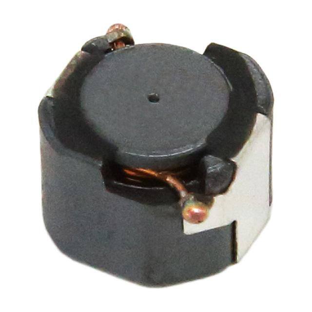
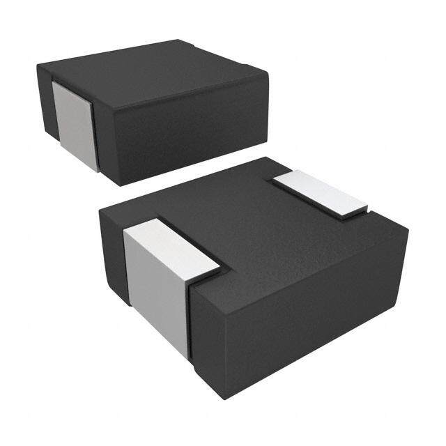
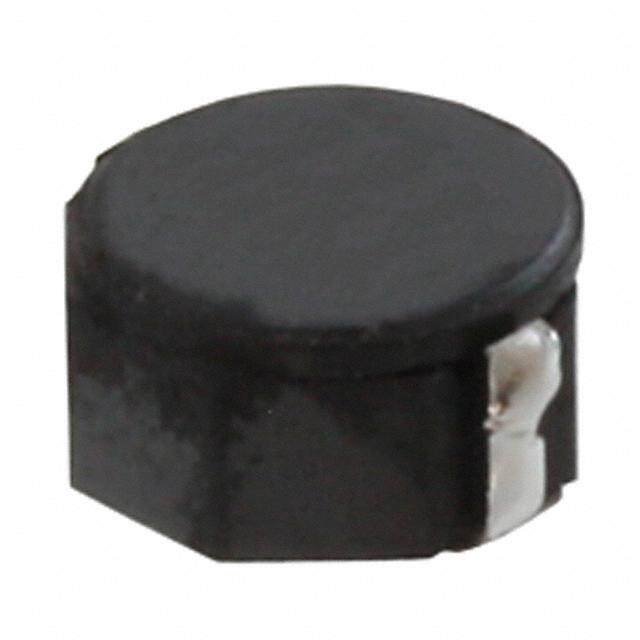
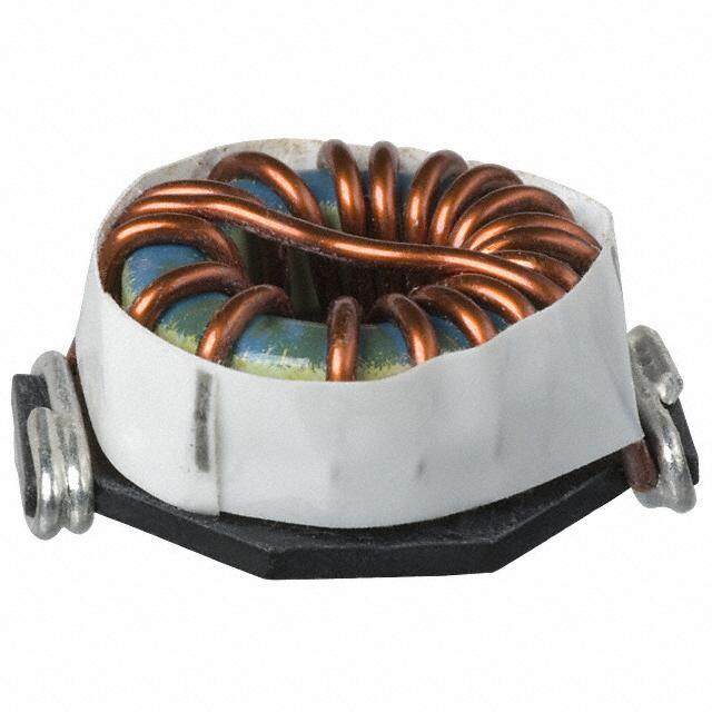
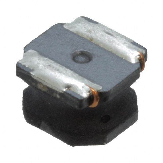
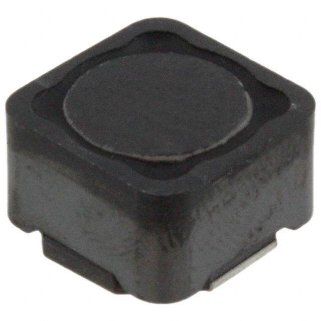
ICGOO电子元器件商城为您提供CLF6045T-680M由TDK设计生产,在icgoo商城现货销售,并且可以通过原厂、代理商等渠道进行代购。 CLF6045T-680M价格参考¥2.38-¥2.38。TDKCLF6045T-680M封装/规格:固定值电感器, 68µH 屏蔽 绕线 电感器 1A 258 毫欧最大 非标准 。您可以下载CLF6045T-680M参考资料、Datasheet数据手册功能说明书,资料中有CLF6045T-680M 详细功能的应用电路图电压和使用方法及教程。
TDK Corporation的CLF6045T-680M是一款固定值电感器,其应用场景主要包括以下几个方面:

1. 电源电路:该电感器适用于开关电源(SMPS)、DC-DC转换器和电压调节模块(VRM)等电源管理电路中。它能够稳定地存储和释放能量,确保输出电压的平稳性,同时减少电磁干扰(EMI)。

2. 滤波电路:CLF6045T-680M可用于音频、视频和其他信号处理电路中的低通、高通或带通滤波器设计。通过与电容器配合使用,它可以有效去除高频噪声,提高信号质量。

3. 汽车电子系统:由于其良好的电气特性和可靠性,这款电感器适合用于汽车电子设备中,如车载信息娱乐系统、导航系统以及电动助力转向系统的电源供应部分。

4. 通信设备:在无线通信基站、路由器及调制解调器等设备中,CLF6045T-680M可以作为匹配网络的一部分,优化射频性能并增强数据传输效率。

5. 工业自动化:在可编程逻辑控制器(PLC)、伺服驱动器和变频器等工业应用中,此电感器有助于实现高效的功率转换和控制功能。

6. 消费类电子产品:例如笔记本电脑适配器、平板电脑充电器以及家用电器内部的电源模块,都可以利用CLF6045T-680M来提升整体性能和稳定性。

总之,CLF6045T-680M凭借其高饱和电流、低直流电阻和紧凑尺寸的特点,在需要高效能量转换和精确滤波的各种电子设备中具有广泛的应用价值。
| 参数 | 数值 |
| 产品目录 | |
| DC电阻(DCR) | 215 毫欧 |
| 描述 | FIXED IND 68UH 1A 215 MOHM SMD |
| 产品分类 | |
| 品牌 | TDK Corporation |
| 数据手册 | |
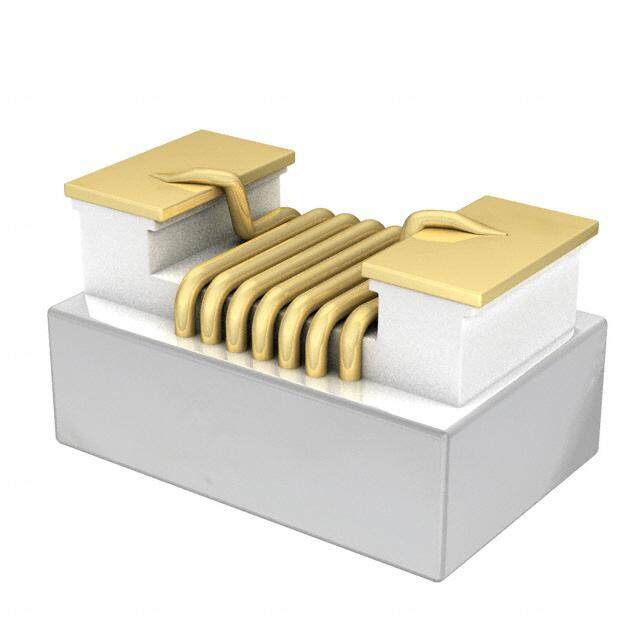
| 产品图片 |
|
| 产品型号 | CLF6045T-680M |
| rohs | 无铅 / 符合限制有害物质指令(RoHS)规范要求 |
| 产品系列 | CLF |
| 不同频率时的Q值 | - |
| 供应商器件封装 | - |
| 其它名称 | 445-15097-1 |
| 包装 | 剪切带 (CT) |
| 大小/尺寸 | 0.244" 长 x 0.232" 宽(6.20mm x 5.90mm) |
| 安装类型 | 表面贴装 |
| 容差 | ±20% |
| 封装/外壳 | 非标准 |
| 屏蔽 | 屏蔽 |
| 工作温度 | -40°C ~ 105°C |
| 材料-磁芯 | - |
| 标准包装 | 1 |
| 电感 | 68µH |
| 电流-饱和值 | 790mA |
| 类型 | 绕线 |
| 频率-测试 | 100kHz |
| 频率-自谐振 | - |
| 额定电流 | 1A |
| 高度-安装(最大值) | 0.177"(4.50mm) |


- 商务部:美国ITC正式对集成电路等产品启动337调查
- 曝三星4nm工艺存在良率问题 高通将骁龙8 Gen1或转产台积电
- 太阳诱电将投资9.5亿元在常州建新厂生产MLCC 预计2023年完工
- 英特尔发布欧洲新工厂建设计划 深化IDM 2.0 战略
- 台积电先进制程称霸业界 有大客户加持明年业绩稳了
- 达到5530亿美元!SIA预计今年全球半导体销售额将创下新高
- 英特尔拟将自动驾驶子公司Mobileye上市 估值或超500亿美元
- 三星加码芯片和SET,合并消费电子和移动部门,撤换高东真等 CEO
- 三星电子宣布重大人事变动 还合并消费电子和移动部门
- 海关总署:前11个月进口集成电路产品价值2.52万亿元 增长14.8%


PDF Datasheet 数据手册内容提取
I N D U C T O R S June 2017 Inductors for Power Circuits Wound Ferrite CLF Series CLF6045 Type CLF6045 Caution The products in this catalog will be or have been stopped production Discontinue Issue Date May 18, 2017 Last Purchase Order Date Mar. 29, 2019 Last Shipment Date Sep. 30, 2019 Please refer to our Web site about replacement information.
(2/9) I N D U C T O R S REMINDERS FOR USING THESE PRODUCTS Before using these products, be sure to request the delivery specifications. n SAFETY REMINDERS e Please pay sufficient attention to the warnings for safe designing when using these products. e b REMINDERS e The storage period is less than 6 months. Be sure to follow the storage conditions (Temperature: 5 to 30°C, Humidity: 10 to 75% RH or v less). If the storage period elapses, the soldering of the terminal electrodes may deteriorate. a n Do not use or store in locations where there are conditions such as gas corrosion (salt, acid, alkali, etc.). h o Before soldering, be sure to preheat components. The preheating temperature should be set so that the temperature difference between the solder temperature and chip temperature r i does not exceed 150°C. o t c Soldering corrections after mounting should be within the range of the conditions determined in the specifications. If overheated, a short circuit, performance deterioration, or lifespan shoretening may ocucur. When embedding a printed circuit board where a chip is mounted to a set, be sure that residual stress is not given to the chip due to b d the overall distortion of the printed circuit board and partial distortion such as at screw tightening portions. o Self heating (temperature increase) occurs when the power is turned ON, so the tolerance should be sufficient for the set thermal l design. l r Carefully lay out the coil for the circuit board design of thei non-magneticp shield type. w A malfunction may occur due to magnetic interference. Use a wrist band to discharge static electricity in your body througdh the grounding wire. Do not expose the products to magnets or magnsetic fields. e t Do not use for a purpose outside of the contents regulatedp in the delivery specifications. c The products listed on this catalog are intended for use in general electronic equipment (AV equipment, telecommunications p equipment, home appliances, amusemeunt equipment, computer equipment, personal equipment, office equipment, measurement equipment, industrial robots) under da normal operaotion and use condition. The products are not designed or warranted to meet the requirements of the applications listed below, whose performance and/or quality require a more stringento level of safety tor reliability, or whose failure, malfunction or trouble could cause serious damage to society, person or property. s If you intend to use the prodructs in the applications listed below or if you have special requirements exceeding the range or conditions set forth in the each cataplog, please contact us. (1) Aerospace/Aviation equipment (8) Public information-processing equipment e (2) Transportation equipment (cars, electric trains, ships, etc.) (9) Military equipment (3) Medical equhipment (10) Electric heating apparatus, burning equipment (4) Power-generation control equipment (11) Disaster prevention/crime prevention equipment T (5) Atomic energy-related equipment (12) Safety equipment (6) Seabed equipment (13) Other applications that are not considered general-purpose (7) Transportation control equipment applications When designing your equipment even for general-purpose applications, you are kindly requested to take into consideration securing protection circuit/device or providing backup circuits in your equipment. 20170612 / inductor_commercial_power_clf6045_en.fm
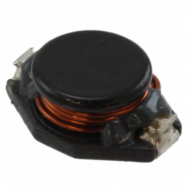
(3/9) I N D U C T O R S Inductors for Power Circuits Product compatible with RoHS directive Compatible with lead-free solders Wound Ferrite Overview of CLF6045 Type n e e FEATURES b Magnetic shield type wound inductor for power circuits. Wide E-6 Series lineup allows for various usages. e v APPLICATION a Thin-screen TVs, LCDs, AV equipment, STBs, LED lights, industrial equipment n h o PART NUMBER CONSTRUCTION r i CLF 6045 T - 1R5o tN c L×W×H Dimensions Inductance Inductance Series name (mm) Packaging style e(µH) utolerance 6045 6.2×5.9×4.5 T Taping 1R0 1.0 M ±20% b d 100 10 N ±30% 101 100 o l l r OPERATING TEMPERATURE RANGE, PACKAGE QUANTITY, PRODUCT WEIGHT i p Temperature range w Package quantity Individual weight Type Operating Storage temperature temperature d (°C) (°C) (pieces/reel) (g) s CLF6045 –40 to +105 –40 to +105 e1000 0.6 Operating temperature range includes self-temperatutre rise. The Storage temperature range is for after the circuit board is mounpted. c p u d o o t s r p e h T RoHS Directive Compliant Product: See the following for more details.https://product.tdk.com/info/en/environment/rohs/index.html Please be sure to request delivery specifications that provide further details on the features and specifications of the products for proper and safe use. Please note that the contents may change without any prior notice due to reasons such as upgrading. 20170612 / inductor_commercial_power_clf6045_en.fm
(4/9) I N D U C T O R S CLF6045 Type RECOMMENDED REFLOW PROFILE n Preheating Soldering Natural cooling e Peak e T4 b e atur T3 T3 er e p m e v T T2 T: t3 a T1 n h t1 t2 o r i o t t: Time c e u Preheating Soldering Peak b d Temp. Time Temp. Time Temp. Time T1 T2 t1 T3 t2 T4 t3 o 150°C 180°C 60 to 120s 230°C 30s 250°C 5s l l r i p w d s e t p c p u d o o t s r p e h T Please be sure to request delivery specifications that provide further details on the features and specifications of the products for proper and safe use. Please note that the contents may change without any prior notice due to reasons such as upgrading. 20170612 / inductor_commercial_power_clf6045_en.fm
(5/9) I N D U C T O R S CLF6045 Type SHAPE & DIMENSIONS 6.2±0.2 n e e 2 1 ±0. 100 ±0. b 9 0 5. 2. e (4.0) v 1.1±0.15 1.1±0.15 a 3 n ±0. h 5 4. )1 o (0. r i o t Dimensions in mm c e u b d RECOMMENDED LAND PATTERN o l 2.2 l r i p 1.7 3.6 1.7 w Dimensions in mm d s e t p c p u d o o t s r p e h T Please be sure to request delivery specifications that provide further details on the features and specifications of the products for proper and safe use. Please note that the contents may change without any prior notice due to reasons such as upgrading. 20170612 / inductor_commercial_power_clf6045_en.fm
(6/9) I N D U C T O R S CLF6045 Type ELECTRICAL CHARACTERISTICS CHARACTERISTICS SPECIFICATION TABLE n L Measuring frequency DC resistance Rated current Part No. e Idc1 Idc2 (µH) Tolerance (kHz) () (A) (A) e 1.0 ±30% 100 11m±30% 5.0 4.5 CLF6045T-1R0N 1.5 ±30% 100 13m±30% 4.4 4.2 CLF6045T-1R5N b 2.2 ±30% 100 15m±30% 3.9 4.0 CLF6045T-2R2N 3.3 ±30% 100 19m±30% 3.1 3.5 CLF6045T-3R3N 4.7 ±30% 100 23m±30% 2.5 3.2 CLF6045T-4R7N e 6.8 ±30% 100 27m±30% 2.2 2.9 CLF6045T-6R8N 10 ±20% 100 38m±20% 1.7 2.4 CLF6045T-100M v 15 ±20% 100 55m±20% 1.5 2.0 CLF6045T-150M 22 ±20% 100 78m±20% 1.3 1.7 CLF6045T-220M a 33 ±20% 100 0.103±20% 1.07 1.5 CLF6045T-330M n 47 ±20% 100 0.130±20% 0.90 1.3 CLF6045T-470M h 68 ±20% 100 0.215±20% 0.79 1.0 CLF6045T-680M o 100 ±20% 100 0.340±20% 0.64 0.70 CLF6045T-101M 150 ±20% 100 0.480±20% 0.50 0.60 CLF6045T-151M r i 220 ±20% 100 0.780±20% 0.41 0.50 CLF6045T-221M o t 330 ±20% 100 0.970±20% 0.35 0.44 CLF6045T-331M 470 ±20% 100 1.42±20% 0.30 c0.37 CLF6045T-471M Rated current: smaller value of either Idc1 or Idc2. e u Idc1: When based on the inductance change rate (10% below the initial value) Idc2: When based on the temperature increase (Temperature increase of 30°C) b d ○Measurement equipment Measurement item Product No. Manufactu rer o L 4285A Keysightl Technologies DC resistance VP-2941A Panaslonic r Rated current Idc1 4285A+42841A+42842C Keyisight Technologipes * Equivalent measurement equipment may be used. w d s e t p c p u d o o t s r p e h T Please be sure to request delivery specifications that provide further details on the features and specifications of the products for proper and safe use. Please note that the contents may change without any prior notice due to reasons such as upgrading. 20170612 / inductor_commercial_power_clf6045_en.fm
(7/9) I N D U C T O R S CLF6045 Type ELECTRICAL CHARACTERISTICS L FREQUENCY CHARACTERISTICS GRAPH n 10000 e e b e 1000 v a 471M n 331M h o 221M 151M r i o t 101M 100 c 680M )H 470M e u µ (ce 330M b d n a ct 220M u o Ind 150M l 100M l r 10 i p 6R8N w 4R7N 3R3N d 2R2N s e 1R5N t p 1R0N c 1 p u d o o t s r p 0.1 10 100 1000 10000 100000 Frequency(kHz) e ○Measuremhent equipment Product No. Manufacturer 4294A T Keysight Technologies * Equivalent measurement equipment may be used. Please be sure to request delivery specifications that provide further details on the features and specifications of the products for proper and safe use. Please note that the contents may change without any prior notice due to reasons such as upgrading. 20170612 / inductor_commercial_power_clf6045_en.fm
(8/9) I N D U C T O R S CLF6045 Type ELECTRICAL CHARACTERISTICS INDUCTANCE VS. DC BIAS CHARACTERISTICS GRAPH n 1000 e e 471M b 331M 221M e 151M v 100 101M a n 680M h o 470M 330M r i o t 220M c )H 150M e u µ (nce 10 100M b d a ct u 6R8N o d In 4R7N l l r 3R3N i p w 2R2N d 1R5N 1R0N s e 1 t p c p u d o o t s r p 0.1 0.1 1 10 DC current(A) e ○Measuremhent equipment Product No. Manufacturer T 4285A+42841A+42842C Keysight Technologies * Equivalent measurement equipment may be used. Please be sure to request delivery specifications that provide further details on the features and specifications of the products for proper and safe use. Please note that the contents may change without any prior notice due to reasons such as upgrading. 20170612 / inductor_commercial_power_clf6045_en.fm
(9/9) I N D U C T O R S CLF6045 Type PACKAGING STYLE REEL DIMENSIONS n 2.0±0.5 E e Type A W1 W2 N E CLF6045 ø330 16.4 22.4 ø50 2 e * These values are typical values. b N e v (1.0) a n h ø13.0±0.5 W1 o ø21.0±0.8 W2 A r i o t Dimensions in mm c e u TAPE DIMENSIONS b d øD0 P2 P0 P1 K E o l F l r W iB p w A t Dimdensions in mm s e t p Type A B øD0 E cF P0 P1 P2 W K t CLF6045 6.4 6.4 1.5+0.1/–0 1.75±0.1 7.5±0.1 4.0±0.1 12.0±0.1 2.0±0.1 16.0±0.3 4.9 0.4 p u d o o t s r p e h T Please be sure to request delivery specifications that provide further details on the features and specifications of the products for proper and safe use. Please note that the contents may change without any prior notice due to reasons such as upgrading. 20170612 / inductor_commercial_power_clf6045_en.fm