ICGOO在线商城 > 电路保护 > 气体放电管避雷器(GDT) > CG2470LTR
 Datasheet下载
- 型号: CG2470LTR
- 制造商: Littelfuse
- 库位|库存: xxxx|xxxx
- 要求:
| 数量阶梯 | 香港交货 | 国内含税 |
| +xxxx | $xxxx | ¥xxxx |
查看当月历史价格
查看今年历史价格
CG2470LTR产品简介:
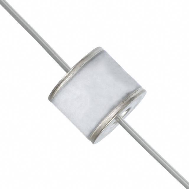
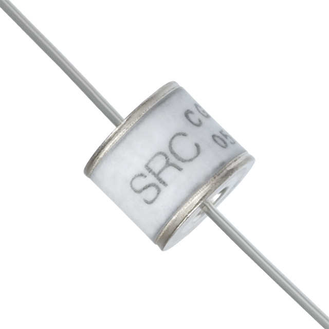
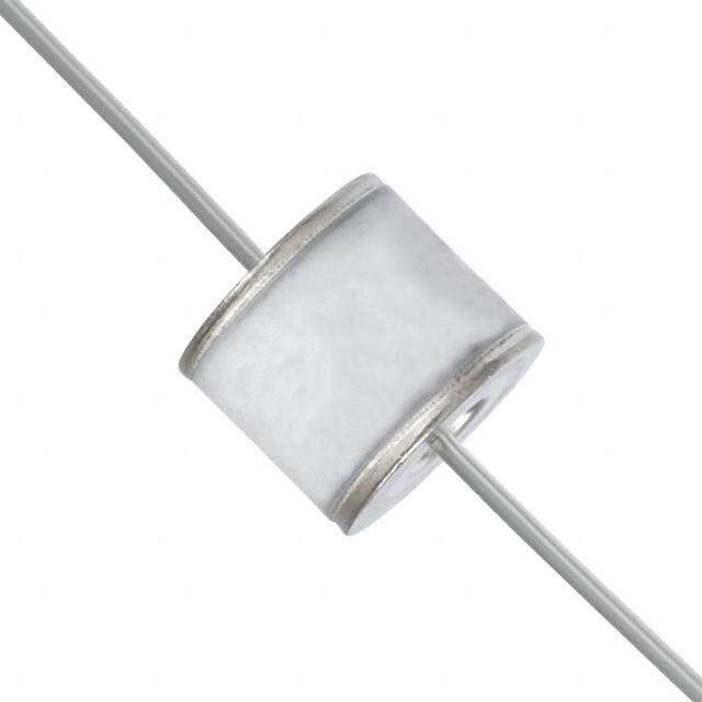
ICGOO电子元器件商城为您提供CG2470LTR由Littelfuse设计生产,在icgoo商城现货销售,并且可以通过原厂、代理商等渠道进行代购。 CG2470LTR价格参考。LittelfuseCG2470LTR封装/规格:气体放电管避雷器(GDT), Gas Discharge Tube 470V 20000A (20kA) 2 Pole Through Hole。您可以下载CG2470LTR参考资料、Datasheet数据手册功能说明书,资料中有CG2470LTR 详细功能的应用电路图电压和使用方法及教程。
Littelfuse Inc. 的CG2470LTR是一款气体放电管避雷器(GDT),主要用于过电压保护,广泛应用于通信设备、电信线路和数据传输系统中。该器件额定击穿电压约为240V,适用于交流和直流电路,能够在雷击或瞬态过电压事件中迅速导通,将高压脉冲泄放到地,从而保护后级敏感电子元件。

典型应用场景包括:电话线路、DSL调制解调器、网络接口卡、安防系统、工业控制设备以及有线电视(CATV)系统等需要高可靠性浪涌防护的场合。CG2470LTR具备高绝缘电阻、低电容特性,对信号传输影响极小,适合高频信号线路的保护。其表面贴装(SMD)封装形式节省空间,便于自动化生产,适用于紧凑型电子设备设计。

此外,该器件符合RoHS环保标准,具有良好的长期稳定性和耐候性,可在较宽温度范围内可靠工作,适合在恶劣环境条件下使用。综上,CG2470LTR是通信与信号线路中实现高效、可靠过压保护的理想选择。
| 参数 | 数值 |
| 产品目录 | |
| 描述 | SURGE ARRESTER GDT 470V AXIAL |
| 产品分类 | 气体放电管避雷器 (GDT) |
| 品牌 | Littelfuse Inc |
| 数据手册 | |
| 产品图片 |
|
| 产品型号 | CG2470LTR |
| rohs | 无铅 / 符合限制有害物质指令(RoHS)规范要求 |
| 产品系列 | CG2 |
| 其它名称 | F4105CT |
| 包装 | 剪切带 (CT) |
| 安装类型 | 通孔 |
| 容差 | - |
| 封装/外壳 | 轴向圆柱形 |
| 故障短接 | 无 |
| 极数 | 2 |
| 标准包装 | 1 |
| 电压-DC火花放电(标称值) | 470V |
| 电流-AC放电(标称值) | 20A |
| 脉冲放电电流(8/20us) | 20kA |


- 商务部:美国ITC正式对集成电路等产品启动337调查
- 曝三星4nm工艺存在良率问题 高通将骁龙8 Gen1或转产台积电
- 太阳诱电将投资9.5亿元在常州建新厂生产MLCC 预计2023年完工
- 英特尔发布欧洲新工厂建设计划 深化IDM 2.0 战略
- 台积电先进制程称霸业界 有大客户加持明年业绩稳了
- 达到5530亿美元!SIA预计今年全球半导体销售额将创下新高
- 英特尔拟将自动驾驶子公司Mobileye上市 估值或超500亿美元
- 三星加码芯片和SET,合并消费电子和移动部门,撤换高东真等 CEO
- 三星电子宣布重大人事变动 还合并消费电子和移动部门
- 海关总署:前11个月进口集成电路产品价值2.52万亿元 增长14.8%


PDF Datasheet 数据手册内容提取
Gas Discharge Tubes CG/CG2 Series CG/CG2 Series RoHS Description Littelfuse’s highly reliable CG/CG2 Series GDTs provide a high degree of surge protection in a small size ideal for board level circuit protection. GDTs function as switches which dissipate a minimum amount of energy and therefore handle currents that far surpass other types of transient voltage protection. Their gas-filled, rugged ceramic metal construction make them well suited to adverse environments. The CG/CG2 series comes in a variety of forms including surface mount, core, straight and shaped Agency Approvals leads, to serve a variety of mounting methods. AGENCY AGENCY FILE NUMBER The CG Series (75V-110V) is ideal for protection of test and communication equipment and other E1286621 devices in which low voltage limits and extremely low arc voltages are required. E3201162 The CG2 Series (145V-1000V) is ideal for protecting NOTES: 1. Certified to UL 497B. equipment where higher voltage limits and holdover 2. Only CG2300, CG2470, CG2600, CG2800 and CG221000. Certified to UL 1449. voltages are necessary. 2 Electrode GDT Graphical Symbol Features • RoHS and Lead-free • Meets REA PE-80 compliant • Available in surface • Rugged Ceramic-Metal mount, and a variety of construction lead options options Additional Information • Low Capacitance • RoHS Compliant and (<1.5pf) Lead-Free Applications Datasheet Resources SSaammpplleess CG/CG2 • Communication lines • Instrumentation circuits and equipment • Medical electronics • CATV equipment • ADSL equipment • Test equipment • Telecom SLIC • Data lines protection • Power supplies © 2017 Littelfuse, Inc. Specifications are subject to change without notice. Revised: 12/12/17
Gas Discharge Tubes CG/CG2 Series Electrical Characteristics Device Specifications (at 25°C) Life Ratings DC Breakdown Impulse Impulse Insulation Capaci- Arc Surge Nominal Nominal AC DC Max in Volts Break- Break- Resistance tance Voltage Life Impulse AC Dischage Holdover Impulse (@100V/s) down down In (@1MHz) (on state (@500A Discharge Discharge Current Voltage2 Discharge in Volts Volts Voltage) Current Current (9 cycle Current 10/1000µs) (@100V/µs) (@1 Kv/µsec) @1Amp (8/20µs) (10x1sec @50Hz) (1 Application Part Min @50-60Hz) @ 10/350µs) Number MIN TYP MAX MAX MIN MAX TYP TYP CG75 60 75 90 400 650 CG90 72 90 108 400 600 1010 Ω 52 V 4kA CG90 SN 72 90 108 400 600 (at 50V) CG110 88 110 132 450 600 CG2145 116 145 174 500 600 80 V CG2145 SN 120 145 174 500 600 CG22301 195 230 265 600 700 CG2230 SN1 184 230 276 600 700 CG2250 213 250 288 625 725 5 shots CG2250 SN 200 250 300 625 725 20 A 400 (@20kA) 100 A CG2300 255 300 345 700 800 1.5 pf 15 V shots CG2300 SN 240 300 360 700 800 1010 Ω 2.5kA CG2350 297 350 403 750 900 (at 100V) CG2350 SN 280 350 420 750 900 135 V CG2420 357 420 483 800 1000 CG24701 400 470 540 850 1200 CG2470 SN1 376 470 564 850 1200 CG26001 510 600 690 1000 1400 CG2600 SN1 480 600 720 1000 1400 CG28001 680 800 920 1200 1500 10 shots 10 A CG210001 850 1000 1150 1500 1600 (@10kA) 65 A NOTES: 1. Certified to UL 1449. 2. Reference REA PE-80, 0.2A. Tested to ITU-T Rec K.12 and REA PE 80 < 150 mSec. 3. 5 x [5 (+) or 5 (-)] applications 20kA 8/20µSec. (75 to 600 volt devices.) 10 x [5 (+) and 5 (-)] applications 10kA 8/20µSec. (800 and 100 volt devices.) Product Characteristics LS, Axial: Glow to arc < 0.5Amps Device: Tin Plated 2–5 Microns transition current Lead Wires: Tin Plated 17.5 ± 12.5 Microns Construction: Ceramic Insulator Glow Voltage 60-160 Volts Core: Materials Device: Tin Plated 17.5 ± 12.5 Microns. Storage and Construction: Ceramic Insulator Operational -40 to +90 MS: Temperature Device: Dull Tin Plated 7–9 Microns Maximum Follow 230 Volts r.m.s, 200 Amps. Construction: Ceramic Insulator On Current1 (800V and 1000V devices tested to UL1449 3rd edition) LF Logo, Voltage and date code; Black in Product Marking positive print © 2017 Littelfuse, Inc. Specifications are subject to change without notice. Revised: 12/12/17
Surface Mount (MS) Dimensions Gas Discharge Tubes CG/CG2 Series TOP VIEW PROFILE VIEW SEMI–PROFILE VIEW SOLDER PAD LAYOUT 8.30 ± 0.1 4 ± 0.2 2.29 [0.090] [0.161 ± 0.0080] 5.58 [0.232] R5.29 [R0.208] 6.05 ± 0.2 [0.268 ± 0.0080] 1.0±03.8ø 8.71 [0.343] Device Dimensions Ø6.81 [0.268] 5.89 [0.232] 9.30 ± 0.2 0.47 ± 0.1 Leaded 'L' Type Straight Axial Devices Leaded 'LS' Type Shaped Lead Devices PROFILE VIEW TOP VIEW PROFILE VIEW TOP VIEW 6.07 ± 0.3 8.10 Max. [0.239 ± 0.012] [0.319 DIA Max.] 0.81 DIA. TYP. [0.032] 8.10 DIA. MAX. [0.319] 8.40 ± 0.3 [0.331 ± 0.012] 6.07 ± 0.15 [0.239 ± 0.006] 0.80 0.004 8.4 ± 0.3 [0.032] 62 ± 2 2 Surfaces 0.40 ± 0.03 [0.331 ± 0.012] 9.85 ± 0.30 [0.0157 ± 0.0012] [0.388 ± 0.012] PROFILE VIEW TOP VIEW SOLDER PAD LAYOUT 11.15 ± 0.30 6.07 ± 0.30 8.10 Max. [0.439 ± 0.012] [0.239 ± 0.012] [0.319 DIA Max.] SOLDER PAD LAYOUT Core Devices 9.85 [0.388] 9.85 [0.388] 8.40 ± 0.3 8.66 [0.341] [0.331 ± 0.012] TOP VIEW PROFILE VIEW SEMI–PROFILE VIEW 8.60 [0.339] [08..01302 M Maaxx..] 6[0.0.273 ±9 0±0.. 81015.0 059] 1.77 [0.070] 2 Su r f0a.0c0e4s 0.40 ± 0.03 [0.383.14 ±± 00..30125].89 [0.[203.023]2] 11.68 [0.460] 1[0.8.007 1] [0.0157 ± 0.0012] 11.65 [0.93.8885 ±± 00..30012] .xaM [0.459] [01.14.3195 ±± 00..30012] 01.8 0.47 ± 0.1 'MS' Type Devices [0.019 ± 0.0039] mm DIMENSIONS [inches] TOP VIEW Littelfuse 16 Voltage Rating 8.30 ± 0.1 PROFILE VIEW SEMI–PROFILE VIEW Trademark 250G Current Rating [0.327 ± 0.0039] 4.00 Shaped Lead XXXX D(fCoaro tanedt Cadcoittdi oLenitatell f[u0s.1e54 7 ±± 0 0.2.0079] 5.58 [0.220] R5.29 i[nRfo0r.m20a8ti]on) 6.05 ± 0.2 1.75 [0.238 ± 0.0079] 1.0±03.8ø 11.50 X25X10X6GX X25X10X6GX X25X10X6GX X25X10X6GX X25X10X6GX [0.3669 .±3 00 .±0 007.29] [0.001.94 7± ± 0 0.0.1039] 24.00 SOLDER PAD LAYOUT 2.29 [0.090] 16.00 12.99 8.71 [0.343] 0.512 (13.0) Arbor (330.0) Hole Dia. 5.89 [0.232] 1.01 (25.7) Direction of Feed © 2017 Littelfuse, Inc. Specifications are subject to change without notice. Revised: 12/12/17
Gas Discharge Tubes CG/CG2 Series Soldering Parameters - Reflow Soldering (Surface Mount Devices) Reflow Condition Pb – Free assembly tP T P Critical Zone - Temperature Min (T ) 150°C Ramp-up TL to TP s(min) T Pre Heat - Temperature Max (T ) 200°C L t - Time (Min to Max) (ts()max) 60 – 180 secs eruTS(max) L s ta Average ramp up rate (Liquidus Temp re Ramp-down 3°C/second max p Preheat (T) to peak mT L S(min) T to T - Ramp-up Rate 5°C/second max eT tS S(max) L - Temperature (T) (Liquidus) 217°C Reflow L 25 - Temperature (tL) 60 – 150 seconds time (tto 2 p5eºCak t ote pmepaekr)ature Time Peak Temperature (T) 260+0/-5 °C P Time within 5°C of actual peak 10 – 30 seconds Temperature (t) p Ramp-down Rate 6°C/second max Time 25°C to peak Temperature (T) 8 minutes Max. P Do not exceed 260°C Soldering Parameters - Wave Soldering (Thru-Hole Devices) Recommended Process Parameters: 300 of board 222468000 PreheaWt:ave Parameter Lead-Free Recommendation m side 220200 (Depends on Flux Activation Temperature) (Typical Industry Recommendation) Measured on botto 111110246800000 S o TTPleedrmmeehrpp ePeeaorrtaa tTtt Tuuimerreeme MM:peainrxaiimmtuuurmem::: 1621050800-01°°°8 CCC0 sMeacxoinmdusm C) - 80 mperature (° 246000 Solder Dwell Time: 2-5 seconds Te 00 10 20 30 40 50 60 70 80 90 100 110 120 130 140 150 160 170 180 190 200 210 220 230 240 Time (Seconds) Preheat Time Cooling Time Dwell Time Soldering Parameters - Hand Soldering Solder Iron Temperature: 350° C +/- 5°C Heating Time: 5 seconds max. © 2017 Littelfuse, Inc. Specifications are subject to change without notice. Revised: 12/12/17
<1.2 Max. Lead Bend <0.8 Max Gas Discharge Tubes 52.4 [2.063] CG/CG2 Series 22.8 [0.898] 6.4 [0.252] 5.0 Pitch [0.197] Packaging Dimensions For 'L' Type Axial Lead Items <1.2 Max. Lead Bend 254.0 - 356.0 [10.0 - 14.0] <0.8 Max 80.0 Direction of Feed 52.4 [3.15] [2.063] 22.8 [0.898] 6.4 [0.252] 5.0 Pitch [0.197] Core and 'MS' Type Items 275.0 [10.83] 10x4 ± 0.1 = 40 ± 0.2 100.0 254.0 - 356.0 [10 x 0.157 ± 0.004 = 1.575 ± 0.008] [3.94] [10.01 .-7 51 4±. 00].1 0[0.4.0 1±6 0 ±.0 05.002] [0.069 ± 0.004] 1.5 DIA.[ 0M.0A5X9.] 4[0 ±.1 507.1 ± 0.004] [726.9.09] 25.0 [0.98] 7.5 ± 0.1 [0.295 ± 0.004] 8.5 ± 0.1 [0.335 ± 0.004] 16 +0.3 / -0.1 17.7 80.0 [0.630 +0.012 / -0.004] Direction of Feed [0.697] [3.15] Direction of Feed 1.5 DIA. MAX. 8.6 ± 0.1 [0.059] 12 ± 0.1 [0.339 ± 0.004] [0.472 ± 0.004] For 'LS' Type Shaped Lead Items 10x4 ± 0.1 = 40 ± 0.2 [10x.157 ± 0.004 = 1.575 ± 0.008] 0[0.5.0 ±20 0 ±.0 50.002] [0.016.795 ± ± 0 0.0.104] 1.5 DIA.[ 0M.0A5X9.] [0.157 ±4 0 ±.0 00.41] [[2172706.95..809.02]][130.903.0] 2[05.9.08] 1.9 [0.075] 11.5 ± 0.1 [215.0.71] [0.453 ± 0.004] Direction of Feed 11.75 ± 0.1 8 ± 0.1 24 +0.3 / -0.1 [0.463 ± 0.004] [0.315 ± 0.004] [0.945 +0.019 / -0.004] 0.5 ± 0.01 [0.020 ± 0.004] 1.5 DIA. MAX. 9 ± 0.1 [0.059] 16 ± 0.1 [0.354 ± 0.004] [0.630 ± 0.004] © 2017 Littelfuse, Inc. Specifications are subject to change without notice. Revised: 12/12/17
Gas Discharge Tubes CG/CG2 Series Part Numbering System and Ordering Information CG2 XXX XX * XX Series Examples: CG -- for 75, 90, or 110V CG2 -- for 145V to 1000V CG75 -- A non-leaded 75V device Breakdown Voltage CG2230L -- A leaded 230V device 75 300 CG2800LTR -- A leaded 800V device, tape-and-reel (per EIA standard RS-296-D) 90 350 110 470 145 600 Notes: 230 800 CG/CG2 devices with other breakdown voltages in the 75-1000 V range are available upon request. 250 1000 Lead Option Code (Blank) = No Leads / Core L = Straight Leads LS = Shaped Leads MS = Surface Mount Option Code* SN = may have different DC Breakover Voltage Limit. Please refer to Electrical Characteristics table for additional information. Packaging Option Code (Blank) = No Leads / Core, Bulk Bag - 400 pcs L(Blank) = Straight Lead, Tray - 50 pcs LTR = Straight Lead, Tape & Reel per EIA RS-296-E - 500 per reel LS(Blank) = Shaped Lead (see LS dimensions), Tape & Reel - 500 per reel Disclaimer Notice - Information furnished is believed to be accurate and reliable. However, users should independently evaluate the suitability of and test each product selected for their own applications. Littelfuse products are not designed for, and may not be used in, all applications. Read complete Disclaimer Notice at: www.littelfuse.com/disclaimer-electronics. © 2017 Littelfuse, Inc. Specifications are subject to change without notice. Revised: 12/12/17