ICGOO在线商城 > 集成电路(IC) > 逻辑 - 信号开关,多路复用器,解码器 > CD22M3494MQZ
- 型号: CD22M3494MQZ
- 制造商: Intersil
- 库位|库存: xxxx|xxxx
- 要求:
| 数量阶梯 | 香港交货 | 国内含税 |
| +xxxx | $xxxx | ¥xxxx |
查看当月历史价格
查看今年历史价格
CD22M3494MQZ产品简介:
ICGOO电子元器件商城为您提供CD22M3494MQZ由Intersil设计生产,在icgoo商城现货销售,并且可以通过原厂、代理商等渠道进行代购。 CD22M3494MQZ价格参考¥38.17-¥38.17。IntersilCD22M3494MQZ封装/规格:逻辑 - 信号开关,多路复用器,解码器, Crosspoint Switch 1 x 16:8 44-PLCC (16.58x16.58)。您可以下载CD22M3494MQZ参考资料、Datasheet数据手册功能说明书,资料中有CD22M3494MQZ 详细功能的应用电路图电压和使用方法及教程。
Renesas Electronics America Inc. 生产的 CD22M3494MQZ 是一款逻辑信号开关、多路复用器和解码器,适用于多种电子系统设计场景。以下是其主要应用场景:

 1. 数据选择与切换
   - 多路复用功能:该器件可以作为多路复用器(MUX),用于从多个输入信号中选择一个信号进行输出。这种功能广泛应用于需要动态切换信号源的场景,例如音频/视频设备中的输入切换。
   - 信号路由:在复杂的电路中,CD22M3494MQZ 可以实现信号路径的灵活控制,确保正确的信号流向目标模块。

 2. 通信系统
   - 在通信设备中,该芯片可用于信号通道的选择和切换,支持多信道系统的高效运行。
   - 适用于无线通信基站、路由器或调制解调器等设备中的信号处理部分。

 3. 工业自动化
   - 传感器信号管理:在工业控制系统中,可使用该器件对来自多个传感器的信号进行选择和传输,从而优化数据采集流程。
   - 控制器接口:为 PLC(可编程逻辑控制器)或其他工业控制器提供灵活的输入/输出信号管理能力。

 4. 消费电子产品
   - 家用电器:如电视、机顶盒等设备中,用于管理和切换不同的输入源(如 HDMI、USB 或天线信号)。
   - 游戏设备:在游戏主机或控制器中,用于处理用户输入和反馈信号的切换。

 5. 汽车电子
   - 车载娱乐系统:用于切换音频、视频或其他多媒体信号源。
   - 传感器网络:管理来自不同传感器的数据流,提高车辆监测系统的效率。

 6. 测试与测量设备
   - 在示波器、信号发生器等仪器中,该芯片可用于选择和分配测试信号,满足多样化的测量需求。

 7. 嵌入式系统
   - 在微控制器或 FPGA 系统中,CD22M3494MQZ 可用于实现信号的高效分配和管理,提升系统的灵活性和性能。

总结来说,CD22M3494MQZ 的多功能性使其适合需要高可靠性和高效信号管理的应用场景,尤其是在需要多路信号切换、数据路由和逻辑控制的复杂系统中。
| 参数 | 数值 |
| 产品目录 | 集成电路 (IC)半导体 |
| 描述 | IC CROSSPOINT SWITCH 16X8 44PLCC模拟和数字交叉点 IC XPOINT AUD 16 X 8MIT EL PIN 44PLCC IND |
| 产品分类 | |
| 品牌 | Intersil |
| 产品手册 | |
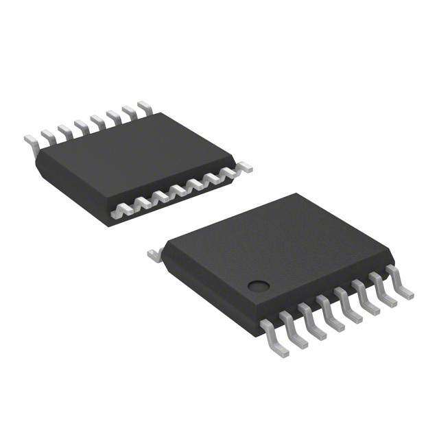
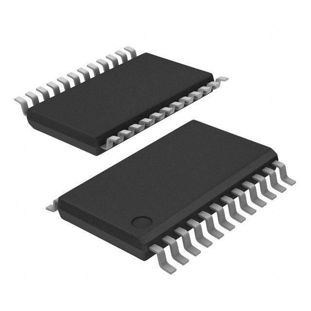
| 产品图片 |
|
| rohs | 符合RoHS无铅 / 符合限制有害物质指令(RoHS)规范要求 |
| 产品系列 | 通信及网络 IC,模拟和数字交叉点 IC,Intersil CD22M3494MQZ- |
| 数据手册 | |
| 产品型号 | CD22M3494MQZ |
| 产品目录页面 | |
| 产品种类 | 模拟和数字交叉点 IC |
| 供应商器件封装 | 44-PLCC |
| 功能 | 交叉点开关 |
| 包装 | 管件 |
| 商标 | Intersil |
| 安装类型 | 表面贴装 |
| 安装风格 | SMD/SMT |
| 导通电阻 | 65 欧姆 |
| 封装 | Tube |
| 封装/外壳 | 44-LCC(J 形引线) |
| 封装/箱体 | PLCC-44 |
| 工作温度 | -40°C ~ 85°C |
| 工作电源电压 | 5 V, 9 V, 12 V |
| 工厂包装数量 | 26 |
| 最大工作温度 | + 85 C |
| 最小工作温度 | - 40 C |
| 标准包装 | 26 |
| 电压-电源,单/双 (±) | 4 V ~ 15 V |
| 电压源 | 单电源 |
| 电流-电源 | 5mA |
| 电源电压-最大 | 15 V |
| 电源电压-最小 | 4 V |
| 电源类型 | Single |
| 电路 | 1 x 16:8 |
| 系列 | CD22M3494 |
| 配置 | 16 x 8 |
| 阵列数量 | 1 |




- 商务部:美国ITC正式对集成电路等产品启动337调查
- 曝三星4nm工艺存在良率问题 高通将骁龙8 Gen1或转产台积电
- 太阳诱电将投资9.5亿元在常州建新厂生产MLCC 预计2023年完工
- 英特尔发布欧洲新工厂建设计划 深化IDM 2.0 战略
- 台积电先进制程称霸业界 有大客户加持明年业绩稳了
- 达到5530亿美元!SIA预计今年全球半导体销售额将创下新高
- 英特尔拟将自动驾驶子公司Mobileye上市 估值或超500亿美元
- 三星加码芯片和SET,合并消费电子和移动部门,撤换高东真等 CEO
- 三星电子宣布重大人事变动 还合并消费电子和移动部门
- 海关总署:前11个月进口集成电路产品价值2.52万亿元 增长14.8%



PDF Datasheet 数据手册内容提取
DATASHEET CD22M3494 FN2793 16 x 8 x 1 BiMOS-E Crosspoint Switch Rev 8.00 May 29, 2014 The Intersil CD22M3494 is an array of 128 analog switches Features capable of handling signals from DC to video. Because of • 128 Analog Switches the switch structure, input signals may swing through the total supply voltage range, VDD to VEE. Each of the 128 • Low rON switches may be addressed via the ADDRESS input to the 7 • Guaranteed rON Matching to 128 line decoder. The state of the addressed switch is established by the signal to the DATA input. A low or zero • Analog Signal Input Voltage Equal to the Supply Voltage input will open the switch, while a high logic level or a one • Wide Operating Voltage. . . . . . . . . . . . . . . . . . 4V to 15V will result in closure of the addressed switch when the STROBE input goes high from its normally low state. Any • Parallel Input Addressing number or combination of connections may be active at one • High Latch-Up Current. . . . . . . . . . . . . . . . . . 50mA (Min) time. Each connection, however, must be made or broken • Very Low Crosstalk individually in the manner previously described. All switches may be reset by taking the RESET input from a zero state to • Pin and Functionally Compatible with the Following Types: a one state and then returning it to its normal low state. SGS M3494 and Mitel MT8816 CS allows crosspoint array to be cascaded for matrix • Pb-Free (RoHS Compliant) expansion. Applications • PBX Systems • Instrumentation • Analog and Digital Multiplexers • Video Switching Networks Block Diagram CS STROBE DATA RESET VDD 1 1 1 AX0 AX1 AX2 AAYX03 D7E TCOO 1D2E8R LATCHES SHLEIFVTEELRS S1W6 IXT C8H X0 - X15 AY1 128 128 128 ARRAY AY2 VSS VEE Y0 - Y7 FN2793 Rev 8.00 Page 1 of 10 May 29, 2014
CD22M3494 Ordering Information PART NUMBER PART TEMP. RANGE PACKAGE PKG. DWG. (Note 3) MARKING (°C) (Pb-Free) # CD22M3494EZ CD22M3494EZ -40 to 85 40 Ld PDIP (Note 2) E40.6 CD22M3494MQZ (Note 1) CD22M3494MQZ -40 to 85 44 Ld PLCC (Mitel Ld Compatible) N44.65 CD22M3494MQAZ (Note 1) CD22M3494MQAZ -40 to 85 44 Ld PLCC (Mitel Ld Compatible) N44.65 CD22M3494SQZ (Note 1) CD22M3494SQZ -40 to 85 44 Ld PLCC (SGS Ld Compatible) N44.65 NOTES: 1. Add “96” suffix for tape and reel. At one time the "QZ" and "QAZ" were different products, but since 1994 these parts have been exactly the same. 2. Pb-free PDIPs can be used for through-hole wave solder processing only. They are not intended for use in Reflow solder processing applications. 3. Intersil Pb-free plus anneal products employ special Pb-free material sets; molding compounds/die attach materials and 100% matte tin plate termination finish, which are RoHS compliant and compatible with both SnPb and Pb-free soldering operations. Intersil Pb-free products are MSL classified at Pb-free peak reflow temperatures that meet or exceed the Pb-free requirements of IPC/JEDEC J STD-020. Pinouts CD22M3494E CD22M3494MQ CD22M3494SQ (PDIP) (PLCC) (MITEL LEAD COMPATIBLE) (PLCC) (SGS LEAD COMPATIBLE) TOP VIEW TOP VIEW TOP VIEW T T AYY23 12 3490 YV2DD NC AX0 AX3 RESE AY2 Y3 VDD Y2 DATA Y1 CS NC AX0 AX3 RESE AY2 Y3 VDD Y2 DATA Y1 Y0 RESET 3 38 DATA 6 5 4 3 2 1 44 43 42 41 40 6 5 4 3 2 1 44 43 42 41 40 AX3 4 37 Y1 AX0 5 36 CS X14 7 39 Y0 X14 7 39 CS X14 6 35 Y0 X15 8 38 NC X15 8 38 NC X15 7 34 NC X6 9 37 X0 X6 9 37 X0 X6 8 33 X0 X710 36 X1 X710 36 X1 X7 9 32 X1 X811 35 X2 X811 35 X2 X8 10 31 X2 X912 34 X3 X912 34 X3 X9 11 30 X3 X1013 33 X4 X1013 33 X4 X10 12 29 X4 X1114 32 X5 X1114 32 X5 X11 13 28 X5 NC15 31 X12 NC15 31 X12 NC 14 27 X12 NC16 30 X13 NC16 30 X13 Y7 15 26 X13 Y717 29 NC VSS 17 29 NC VSS 16 25 AY1 Y6 17 24 AY0 18 19 20 21 22 23 24 25 26 27 28 18 19 20 21 22 23 24 25 26 27 28 STROBE 18 23 AX2 VSS Y6 OBE Y5 VEE Y4 AX1 AX2 AY0 AY1 NC Y7 Y6 OBE Y5 VEE Y4 AX1 AX2 AY0 AY1 NC Y5 19 22 AX1 R R T T VEE 20 21 Y4 S S FN2793 Rev 8.00 Page 2 of 10 May 29, 2014
CD22M3494 Pin Descriptions 44 LD PLCC PIN NO. 40 LD PDIP SYMBOL PIN NO. MQ SQ DESCRIPTION POWER SUPPLIES VDD 40 44 44 Positive Supply. VSS 16 18 17 Negative Supply (Digital). VEE 20 22 22 Negative Supply (Analog). ADDRESS AX0 - AX3 5, 22, 23 and 4 5, 24, 25 and 4 X Address Lines. These pins select one of the 16 rows of switches. See the Truth Table on page 7 for the valid addresses. AY0 - AY2 24, 25 and 2 26, 27 and 2 Y Address Lines. These pins select one of the 8 columns of switches. See the Truth Table on page 7 for the valid addresses. CONTROL DATA 38 42 DATA Input determines the state of the addressed switch. A high or one will close the switch. A low or zero will open the switch. STROBE 18 20 STROBE Input enables the action defined by the DATA and ADDRESS Inputs. A low or zero results in no action. The ADDRESS Input must be stable before the STROBE Input goes to the active high level. The DATA Input must be stable on the failing edge of the STROBE. RESET 3 3 MASTER RESET. A high or one on this line opens all switches. CS 36 40 39 CHIP SELECT. Device is selected when CS is at a high level, allows the crosspoint array to be cascaded for matrix expansion. INPUTS/OUTPUTS X0 - X5 33-28, 8-13, 27, 37-32, 9-14, 31, 30, 7, 8 Analog or Digital Inputs/Outputs. These pins are the rows X0 - X15. X6 - X11 26, 6, 7 X12 - X15 Y0 - Y7 35, 37, 39, 1, 21, 39, 41, 43, 1, 23, 40, 41, 43, 1, 23, Analog or Digital Inputs/Outputs. These pins are the columns Y0 - Y7. I/O 19, 17, 15 21, 19, 17 21, 19, 18 FN2793 Rev 8.00 Page 3 of 10 May 29, 2014
CD22M3494 Absolute Maximum Ratings Thermal Information DC Supply Voltage (VDD) Thermal Resistance (Typical, Note 4) JA (°C/W) Voltages Referenced to VEE . . . . . . . . . . . . . . . . . . .-0.5V to 16V PDIP Package* . . . . . . . . . . . . . . . . . . . . . . . . . . . . 55 DC Supply Voltage (VDD) PLCC Package. . . . . . . . . . . . . . . . . . . . . . . . . . . . . 43 Voltages Referenced to VSS . . . . . . . . . . . . . . . . . . .-0.5V to 16V Maximum Junction Temperature Plastic Package. . . . . . . . .+150°C DC Input Diode Current, IIN Maximum Storage Temperature Range (TSTG). . . .-65°C to +150°C For VI, Digital < VSS -0.5V or VI, Pb-Free Reflow Profile. . . . . . . . . . . . . . . . . . . . . . . . . . . see TB493 Analog < VEE -0.5V or VI > VDD 0.5V . . . . . . . . . . . . . . . . . ±20mA *Pb-free PDIPs can be used for through hole wave solder processing DC Output Diode Current, IOK only. They are not intended for use in Reflow solder processing. For VO, Digital < VSS -0.5V or VO, applications. Analog < VEE -0.5V or VO > VDD 0.5V. . . . . . . . . . . . . . . . . ±20mA DC Transmission Gate Current . . . . . . . . . . . . . . . . . . . . . . . ±25mA Operating Conditions Power Dissipation Per Package (Po) For TA = -40°C to +85°C (PDIP). . . . . . . . . . . . . . . . . . . . .500mW Operating Temperature Range (TA) For TA = -40°C to +85°C (PLCC). . . . . . . . . . . . . . . . . . . .600mW Package Type E and Q . . . . . . . . . . . . . . . . . . . . .-40°C to +85°C Supply Voltage Range For TA = Full Package Temperature Range VSS = 0V, VEE = 0V, VDD. . . . . . . . . . . . . . . . . . . . . . .4V to 15V DC Input or Output Voltage VI or VO. . . . . . . . . . . . . . . VEE to VDD Digital Input Voltage. . . . . . . . . . . . . . . . . . . . . . . . . . . . VSS to VDD CAUTION: Stresses above those listed in “Absolute Maximum Ratings” may cause permanent damage to the device. This is a stress only rating and operation of the device at these or any other conditions above those indicated in the operational sections of this specification is not implied. NOTE: 4. JA is measured with the component mounted on an evaluation PC board in free air. Electrical Specifications TA = -40°C to +85°C, VDD = 5V, VSS = 0V, VEE = 0V, Unless Otherwise Specified PARAMETER SYMBOL TEST CONDITIONS MIN TYP MAX UNITS STATIC CONTROLS Supply Current IDD VDD = 5V, Logic Inputs = VDD - - 2 mA VDD = 15V, Logic Inputs = VDD - - 5 mA High-Level Input Voltage VIH VDD = 5V 2.4 - - V (Note 5) Low-Level Input Voltage VIL - - 0.8 V (Note 5) Input Leakage Current, Digital IIN Reset = Low (Note 6) - - ±10 µA (Note 7) Electrical Specifications TA = -40°C to +85°C, VDD = 12V, VSS = 0V, VEE = 0V, Unless Otherwise Specified. PARAMETER SYMBOL TEST CONDITIONS MIN TYP MAX UNITS STATIC CROSSPOINTS ON Resistance rON VSS = VEE = 0V, VDD = 10V - 40 75 TA = +25°C, VIN = VDD/2, VX - VY = 0.2V VDD = 12V - 36 65 ON Resistance rON TA = -40°C to +85°C, VDD = 10V - 50 75 VIN = VDD/2, VX -VY = 0.2V, VSS = VEE = 0V VDD = 12V - 45 65 Difference in ON Resistance rON TA = +25°C, VIN = VDD/2, VX - VY = 0.2V, - 6 10 Between Any Two Switches VSS = VEE = 0V, VDD = 12V FN2793 Rev 8.00 Page 4 of 10 May 29, 2014
CD22M3494 Electrical Specifications TA = -40°C to +85°C, VDD = 12V, VSS = 0V, VEE = 0V, Unless Otherwise Specified. (Continued) PARAMETER SYMBOL TEST CONDITIONS MIN TYP MAX UNITS Difference in ON Resistance rON TA = -40°C to +85°C, VIN = VDD/2, - - 10 Between Any Two Switches VX - VY = 0.2V, VDD = 12V VSS = VEE = 0V, VDD = 12V OFF-State Leakage Current IL |VX - VY| = 12V - - ±10 µA (Note 7) E lectrical Specifications TA = +25°C, VSS = 0V, VEE = 0V, VDD = 14V, CL = 50pF, Unless Otherwise Specified. PARAMETER TEST CONDITIONS MIN TYP MAX UNITS DYNAMIC CROSSPOINTS Switch I/O Capacitance VIN = VDD/2, f = 1MHz - - 20 pF Switch Feedthrough Capacitance VIN = VDD/2, f = 1MHz - 0.3 - pF Propagation Delay Time (Switch ON) - 5 30 ns Signal Input to Output, tPHL or tPLH Frequency Response Channel ON CL = 3pF, RL = 75, VIN = 2VP-P - 50 - MHz f = 20log (VX/VY) = -3dB Total Harmonic, THD VIN = 2VP-P, f = 1kHz - 0.01 - % Feedthrough Channel OFF VIN = 2VP-P, f = 1kHz - -95 - dB Feedthrough = 20log (VX/VY) = FDT Frequency for Signal Crosstalk, fCT 40dB VIN = 2VP-P, RL = 75 - 10 - MHz Attenuation of: 110dB VIN = 2VP-P, RL = 1k || 10pF - 5 - kHz Control Crosstalk Control Input = 3VP-P - 75 - mVPEAK DATA-Input, ADDRESS, Square Wave, tR = tF = 10ns or STROBE to Output RIN = 1K, ROUT = 10k || 10pF Electrical Specifications TA = +25°C, VSS = 0V, VEE = 0V, VDD = 14V, RL = 1k || 50pF, Unless Otherwise Specified. PARAMETER SYMBOL TEST CONDITIONS MIN TYP MAX UNITS DYNAMIC CONTROLS Digital Input Capacitance CIN VIN = 5V, f = 1MHz - 5 - pF Propagation Delay Time STROBE to Output Switch Turn-ON tPSN - 50 100 ns Switch Turn-OFF tPSF - 50 100 ns DATA-IN to Output Turn-ON to High Level tPZH - 60 100 ns Turn-ON to Low Level tPZL - 70 100 ns ADDRESS to Output Turn-ON to High Level tPAN - 70 - ns Turn-OFF to Low Level tPAF - 70 - ns FN2793 Rev 8.00 Page 5 of 10 May 29, 2014
CD22M3494 Electrical Specifications TA = +25°C, VSS = 0V, VEE = 0V, VDD = 14V, RL = 1k || 50pF, Unless Otherwise Specified. (Continued) PARAMETER SYMBOL TEST CONDITIONS MIN TYP MAX UNITS Setup Time CS to STROBE tCS 10 - - ns DATA-IN to STROBE tDS 10 - - ns ADDRESS to STROBE tAS 10 - - ns Hold Time STROBE to CS tCH 10 - - ns ADDRESS to CS 10 - - ns STROBE to DATA-IN tDH 20 - - ns STROBE to ADDRESS tAH 10 - - ns DATA-IN to CS 20 - - ns Pulse Width STROBE tSPW 20 - - ns RESET tRPW 20 - - ns RESET Turn-OFF to Output Delay tPHZ - 70 100 ns NOTES: 5. Operation of VIH at 2.4V or VIL at 0.8V will result in much higher supply current (IDD) than for logic inputs equal to VDD or VSS respectively. 6. Reset IIH < 20µA, Reset = VIH. 7. At +25°C Limit is 100nA. FN2793 Rev 8.00 Page 6 of 10 May 29, 2014
CD22M3494 Timing Diagram tCS tCH CS 50% 50% ADDRESS 50% 50% tAS tSPW tAH tPSN STROBE 50% tPSF tDH tDS DATA 50% 50% tRPW RESET 50% 50% tPAF tPHZ tPZL SWITCH 90% 90% OUTPUT 10% 10% tPZH tPAN TRUTH TABLE X AXIS TRUTH TABLE Y AXIS X ADDRESS Y ADDRESS AX3 AX2 AX1 AX0 X SWITCH AY2 AY1 AY0 Y SWITCH 0 0 0 0 X0 0 0 0 Y0 0 0 1 Y1 0 0 0 1 X1 0 1 0 Y2 0 0 1 0 X2 0 1 1 Y3 0 0 1 1 X3 1 0 0 Y4 0 1 0 0 X4 1 0 1 Y5 0 1 0 1 X5 1 1 0 Y6 0 1 1 0 X12 1 1 1 Y7 0 1 1 1 X13 1 0 0 0 X6 1 0 0 1 X7 1 0 1 0 X8 1 0 1 1 X9 1 1 0 0 X10 1 1 0 1 X11 1 1 1 0 X14 1 1 1 1 X15 FN2793 Rev 8.00 Page 7 of 10 May 29, 2014
CD22M3494 To make a connection (close switch) between any two points, specify an “X” address, a “Y” address, set “DATA” high, and switch “STROBE” from low to high. To break a connection, follow this same procedure with “DATA” low. Example: X ADDRESS Y ADDRESS DATA AX3 AX2 AX1 AX0 AY2 AY1 AY0 To connect switch X3 to switch Y4: 1 0 0 1 1 1 0 0 To connect switch X6 to switch Y7: 1 1 0 0 0 1 1 1 To break connection from X3 to Y4: 0 0 0 1 1 1 0 0 Typical Performance Curve 70 rON vs VIN AT -55°C, +25°C AND +85°C 60 VEE = -6V, VSS = 0V, VDD = 6V ) 50 E ( +85°C C N 40 A T +25°C S SI 30 E R -40°C N O 20 10 0 -8 -6 -4 -2 0 2 4 6 8 VIN (V) © Copyright Intersil Americas LLC 2000-2014. All Rights Reserved. All trademarks and registered trademarks are the property of their respective owners. For additional products, see www.intersil.com/en/products.html Intersil products are manufactured, assembled and tested utilizing ISO9001 quality systems as noted in the quality certifications found at www.intersil.com/en/support/qualandreliability.html Intersil products are sold by description only. Intersil may modify the circuit design and/or specifications of products at any time without notice, provided that such modification does not, in Intersil's sole judgment, affect the form, fit or function of the product. Accordingly, the reader is cautioned to verify that datasheets are current before placing orders. Information furnished by Intersil is believed to be accurate and reliable. However, no responsibility is assumed by Intersil or its subsidiaries for its use; nor for any infringements of patents or other rights of third parties which may result from its use. No license is granted by implication or otherwise under any patent or patent rights of Intersil or its subsidiaries. For information regarding Intersil Corporation and its products, see www.intersil.com FN2793 Rev 8.00 Page 8 of 10 May 29, 2014
CD22M3494 Plastic Leaded Chip Carrier Packages (PLCC) 0.042 (1.07) N44.65 (JEDEC MS-018AC ISSUE A) 0.042 (1.07) 0.048 (1.22) 0.004 (0.10) C 44 LEAD PLASTIC LEADED CHIP CARRIER PACKAGE 0.056 (1.42) PIN (1) IDENTIFIER 0.050 (1.27) TP 0.025 (0.64) INCHES MILLIMETERS R 0.045 (1.14) CL SYMBOL MIN MAX MIN MAX NOTES A 0.165 0.180 4.20 4.57 - A1 0.090 0.120 2.29 3.04 - D2/E2 D 0.685 0.695 17.40 17.65 - CL D1 0.650 0.656 16.51 16.66 3 E1 E D2 0.291 0.319 7.40 8.10 4, 5 D2/E2 E 0.685 0.695 17.40 17.65 - VIEW “A” E1 0.650 0.656 16.51 16.66 3 E2 0.291 0.319 7.40 8.10 4, 5 0.020 (0.51) N 44 44 6 MIN D1 A1 Rev. 2 11/97 D A SEATING 0.020 (0.51) MAX -C- PLANE 3 PLCS 0.026 (0.66) 0.032 (0.81) 0.013 (0.33) 0.021 (0.53) 0.025 (0.64) 0.045 (1.14) MIN MIN VIEW “A” TYP. NOTES: 1. Controlling dimension: INCH. Converted millimeter dimensions are not necessarily exact. 2. Dimensions and tolerancing per ANSI Y14.5M-1982. 3. Dimensions D1 and E1 do not include mold protrusions. Allowable mold protrusion is 0.010 inch (0.25mm) per side. Dimensions D1 and E1 include mold mismatch and are measured at the extreme material condition at the body parting line. 4. To be measured at seating plane -C- contact point. 5. Centerline to be determined where center leads exit plastic body. 6. “N” is the number of terminal positions. FN2793 Rev 8.00 Page 9 of 10 May 29, 2014
CD22M3494 Dual-In-Line Plastic Packages (PDIP) E40.6 (JEDEC MS-011-AC ISSUE B) N 40 LEAD DUAL-IN-LINE PLASTIC PACKAGE E1 INDEX INCHES MILLIMETERS AREA 1 2 3 N/2 SYMBOL MIN MAX MIN MAX NOTES -B- A - 0.250 - 6.35 4 -A- A1 0.015 - 0.39 - 4 D E BASE A2 0.125 0.195 3.18 4.95 - PLANE A2 -C- A B 0.014 0.022 0.356 0.558 - SEATING PLANE L CL B1 0.030 0.070 0.77 1.77 8 D1 D1 A1 eA C 0.008 0.015 0.204 0.381 - B1 e eC C D 1.980 2.095 50.3 53.2 5 B e D1 0.005 - 0.13 - 5 B 0.010 (0.25) M C A B S E 0.600 0.625 15.24 15.87 6 NOTES: E1 0.485 0.580 12.32 14.73 5 1. Controlling Dimensions: INCH. In case of conflict between English e 0.100 BSC 2.54 BSC - and Metric dimensions, the inch dimensions control. eA 0.600 BSC 15.24 BSC 6 2. Dimensioning and tolerancing per ANSI Y14.5M-1982. eB - 0.700 - 17.78 7 3. Symbols are defined in the “MO Series Symbol List” in Section 2.2 of Publication No. 95. L 0.115 0.200 2.93 5.08 4 4. Dimensions A, A1 and L are measured with the package seated in N 40 40 9 JEDEC seating plane gauge GS-3. Rev. 0 12/93 5. D, D1, and E1 dimensions do not include mold flash or protrusions. Mold flash or protrusions shall not exceed 0.010 inch (0.25mm). 6. E and eA are measured with the leads constrained to be per- pendicular to datum -C- . 7. eB and eC are measured at the lead tips with the leads uncon- strained. eC must be zero or greater. 8. B1 maximum dimensions do not include dambar protrusions. Dam- bar protrusions shall not exceed 0.010 inch (0.25mm). 9. N is the maximum number of terminal positions. 10. Corner leads (1, N, N/2 and N/2 + 1) for E8.3, E16.3, E18.3, E28.3, E42.6 will have a B1 dimension of 0.030 - 0.045 inch (0.76 - 1.14mm). FN2793 Rev 8.00 Page 10 of 10 May 29, 2014

 Datasheet下载
.jpg)