
 Datasheet下载
- 型号: CA20COME28-12PBA176
- 制造商: ITT CANNON
- 库位|库存: xxxx|xxxx
- 要求:
| 数量阶梯 | 香港交货 | 国内含税 |
| +xxxx | $xxxx | ¥xxxx |
查看当月历史价格
查看今年历史价格
CA20COME28-12PBA176产品简介:
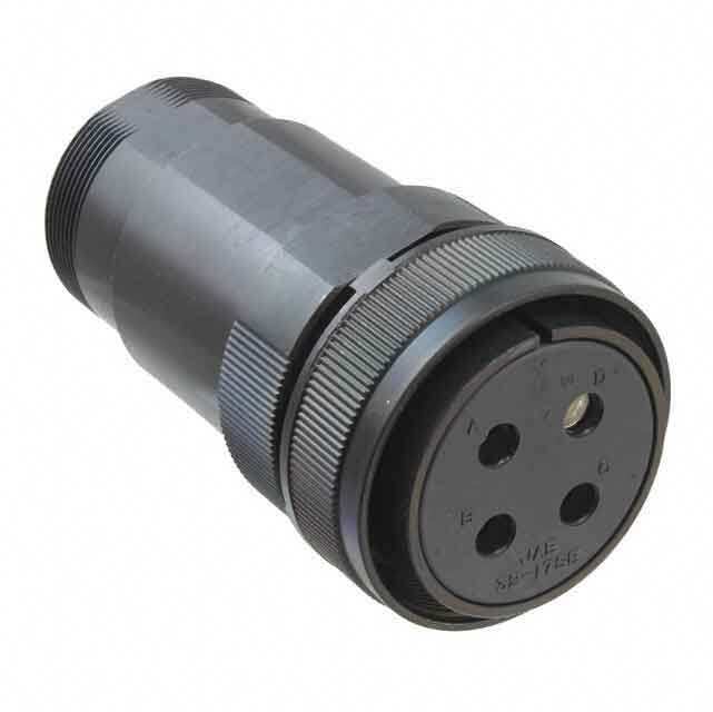
ICGOO电子元器件商城为您提供CA20COME28-12PBA176由ITT CANNON设计生产,在icgoo商城现货销售,并且可以通过原厂、代理商等渠道进行代购。 CA20COME28-12PBA176价格参考。ITT CANNONCA20COME28-12PBA176封装/规格:圆形连接器, 26 Position Circular Connector Receptacle, Male Pins Solder Cup Gold。您可以下载CA20COME28-12PBA176参考资料、Datasheet数据手册功能说明书,资料中有CA20COME28-12PBA176 详细功能的应用电路图电压和使用方法及教程。
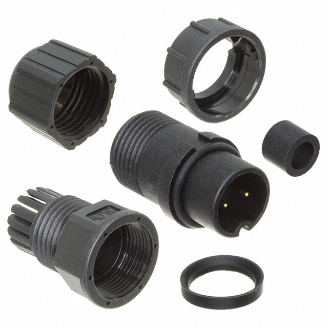
ITT Cannon, LLC 的 CA20COME28-12PBA176 是一款高性能圆形连接器,属于Cannon 20系列,广泛应用于对可靠性与环境耐受性要求严苛的工业和军事领域。该型号具备优良的防尘、防水性能(通常符合MIL-DTL-5015标准),适用于振动大、温度变化剧烈或存在电磁干扰的恶劣环境。

典型应用场景包括航空航天设备中的机载系统连接、地面支持设备、军用车辆及通信系统;在工业领域,常用于重型机械、自动化控制系统、石油天然气勘探设备以及轨道交通系统中的信号与电源传输。其坚固的金属外壳设计确保在冲击、震动和潮湿条件下仍能稳定工作。

此外,该连接器支持多针配置(12针),适合需要高密度电气连接的场合,能够可靠传输电力、控制信号和数据信号。由于其具备良好的电磁屏蔽性能和耐腐蚀特性,也适用于航海设备和户外通信基站等环境。

总之,CA20COME28-12PBA176凭借其耐用性、可靠性和广泛的工作温度范围,成为军工、航空、重工业等领域中关键电气连接的理想选择。
| 参数 | 数值 |
| 产品目录 | |
| 描述 | CONN RCPT 26POS BOX MNT W/PINS |
| 产品分类 | |
| 品牌 | ITT Cannon |
| 数据手册 | |
| 产品图片 | |
| 产品型号 | CA20COME28-12PBA176 |
| rohs | 含铅 / 不符合限制有害物质指令(RoHS)规范要求 |
| 产品系列 | MIL-DTL-5015, CA-COM-B |
| 侵入防护 | IP67 - 防尘,防水 |
| 其它名称 | CA20COME2812PBA176 |
| 包装 | 散装 |
| 外壳尺寸-插件 | 28-12 |
| 外壳尺寸,MIL | - |
| 外壳材料,镀层 | 铝合金, 锌压铸件, 镀镍 |
| 安装类型 | 面板安装,法兰 |
| 工作温度 | -55°C ~ 125°C |
| 朝向 | N(正常型) |
| 标准包装 | 1 |
| 特性 | - |
| 电压-额定 | 500VAC,700VDC |
| 端接 | 焊杯 |
| 紧固类型 | 反向插销锁 |
| 触头镀层 | 金 |
| 触头镀层厚度 | 19.7µin (0.50µm) |
| 连接器类型 | 插座,公形引脚 |
| 针脚数 | 26 |
| 额定电流 | 22A |

.jpg)


- 商务部:美国ITC正式对集成电路等产品启动337调查
- 曝三星4nm工艺存在良率问题 高通将骁龙8 Gen1或转产台积电
- 太阳诱电将投资9.5亿元在常州建新厂生产MLCC 预计2023年完工
- 英特尔发布欧洲新工厂建设计划 深化IDM 2.0 战略
- 台积电先进制程称霸业界 有大客户加持明年业绩稳了
- 达到5530亿美元!SIA预计今年全球半导体销售额将创下新高
- 英特尔拟将自动驾驶子公司Mobileye上市 估值或超500亿美元
- 三星加码芯片和SET,合并消费电子和移动部门,撤换高东真等 CEO
- 三星电子宣布重大人事变动 还合并消费电子和移动部门
- 海关总署:前11个月进口集成电路产品价值2.52万亿元 增长14.8%


.jpg)
PDF Datasheet 数据手册内容提取
CA-COM Industrial Connectors
ITT Inc. ITT is a diversified leading manufacturer of highly engineered critical components and customized technology solutions for the energy, transportation and industrial markets. Building on its heritage of innovation, ITT partners with its customers to deliver enduring solutions to the key industries that underpin our modern way of life. Founded in 1920, ITT is headquartered in White Plains, N. Y., with employees in more than 35 countries and sales in a total of approximately 125 countries. For more information, visit www.itt.com. Our connector portfolio remains the most extensive in the industry, offering a reliable and cost effective range of interconnect solutions with the brands of Cannon, VEAM and BIW Connector Systems. Continuous investment in technology and research & development have enabled ITT to provide new, innovative products and solutions to markets including: 2 www.ittcannon.com
lndustrial / lnstrumentation Transportation Defense Vehicles Oil & Gas Automotive Commercial & Military Aerospace Our connector portfolio remains the most extensive in the industry, offering a reliable and cost effective range of interconnect solutions Computer, Telecom & Consumer Electronics www.ittcannon.com 3
Introduction to CA-COM ITT Cannon’s circular connector’s series CA-COM and CA-COM-B are derivations of the connectors know as SAE-AS50151 (formerly MIL-DTL-5015) and VG95234. Initially designed for military aircraft and combat vehicle application the CA-COM versions have been modified especially for the utilization in various industrial areas. Connectors of both CA-COM series are intermateable and interchangeable with the corresponding types as per SAE-AS50151 and VG95234 as they offer the same mounting dimensions and contact arrangements. The entire CA-COM connector line is ROHS compliant. Features and benefits • The CA-COM standard version is featured by a threaded coupling system while the CA-COM-B types are coined by a “Reverse bayonet” coupling mechanism that offers exceptional vibration protection by a simple 120° turn. The CA-COM-B coupling unit is featured by roller bolts made of stainless steel rolling down the mating ramp, thus reducing coupling torque. • Various backshell and adapter options, like PG metric gland and heatshrink boot are available amongst others. • Insulators are made of high quality polychloroprene, which are good for temperatures up to 125°. This material is self-extinguishing, resistant against various fluids like gasoline, lubricants and other fluids of such nature (short time wetting only). In case of lifetime moistening FKM insulator material can be offered as an alternative. • The contacts are made of copper alloy plated with hard silver finish good for at least 500 mating cycles. There are solder, crimp and PCB contacts in place. The crimp contacts offer a comprehensive range of termination reductions (see pages 41 and 42). • All solder contacts are ROHS compliant due to a special passivation. Contact us for detail or your request for a customized solution. Vital Information: 2D and 3 D drawings, connector specifications are available on ITT Cannon#s web page: www.ittcannon.com Please insert the full connector part number into the keyword search field. Dimensions shown in mm | Specifications and dimensions subject to change 4 www.ittcannon.com
Table of contents How to use this catalogue .................................... 6 Product overview ...................................................7 Part number creation ........................................8 – 9 Ordering reference ...............................................10 Contact arrangements ....................................11–15 Mounting dimensions ..........................................16 Seperating and coupling dimensions ....................17 Wall mounting receptacles with endbells .......18 – 21 Cable connecting plugs .................................22 – 25 Wall mounting receptacles ............................26 – 29 Straight Plugs ................................................30 – 33 Right Angle Plugs .........................................34 – 36 Accessories – Protective caps .........................37 – 38 Accessories ...................................................39 – 40 Contacts .......................................................41 – 42 Tooling..........................................................43 – 44 Product safety information ...................................45 Dimensions shown in mm | Specifications and dimensions subject to change www.ittcannon.com 5
How to use This catalog is split in several sections that help you to • Get an impression what this product is all about (Introduction) • Get a general overview of all product lines (product overview) • Get all required detail information (contact arrangements, product details) • Get all required supporting products (accessories and tooling) The fastest way to find your product of choice is to follow these steps 1 3 Select your product using either the “part number creation” Add accessories and tooling options on the related or the “ordering reference” option pages. A connector assembly instruction is available upon request or visit www.ittcannon.com: Enter Keyword "CA Bayonet Assembly Instruction" 4 2 Use the detail pages to better understand the available Use the contact information on the back cover to contact options like connector styles, contact arrangements and us for further questions or to get advise on where you can contacts options purchase our products Dimensions shown in mm | Specifications and dimensions subject to change 6 www.ittcannon.com
Product overview ELECTRICAL DATA Test voltage Contact Rating at 20°C (68°F), ambient temperature Service rating Test voltage Vrms Contact size (AWG/metric) Rated Current (A max.) ¹ Instruments 1050 16S /15S 22 A 1600 16 /15 22 B 4500 12 41 D 2500 8/60/100 74 E 3000 4 /160 135 0 /500 245 MECHANICAL FEATURES Ambient temperature ¹ T his applies only to the max. rated current for one contact. If several contacts in one contact arrangement are loaded with higher current the temperature –55/125°C (– 67/257°F) may not exceed 125°C ENVIRONMENTAL SEALING Acc. to DIN EN 60068-1 Rated Current vs. Ambient Temperature Threaded: Up to IP 65 (in mated condition) Bayonet: Up to IP 67 (in mated condition) Mating Cycles min. 500 Min. Separating Force per Contact Contact size Separating force metric AWG N min 15S /15 16S /16 1,0 25 12 1,5 60/100 8 3,0 160 4 4,0 500 0 8,5 Contact Retention Apply test force in mating direction Contact size Test force metric AWG N 15S /15 16S /16 35 25 12 55 60/100 8 80 160 4 90 500 0 95 Coupling Torque The admissible coupling torque has to be tested under harnessed condition Contacts Resistance (Millivolt test) Contact size Contact resistance Admissible torque (AWG/metric) mΩ max. Closing and opening (Nmmax) Opening (Nmmin) 16S /15S 6,0 Shell size CA-COM CA-COM-B 16 /15 6,0 10SL 3,0 1,7 0,15 12/25 3,0 12S 2,8 2,5 0,23 8 /100 1,0 14S 5,9 3,6 0,35 4 /160 0,3 16S/16 7,0 5,5 0,46 0 /500 0,2 18 8,0 8,0 0,58 20 9,0 9,0 0,70 Insulation Resistance ≥ 1000 MΩ 22 10,6 11,0 0,80 24 12,9 14,0 0,80 Air and Creepage Path (min.) 28 16,7 17,0 0,92 Voltage class Instr. A D 32 18,1 19,0 1,02 Air path, mm 0,7 1,1 2,8 36 23,9 23,0 1,05 Creepage path, mm 0,7 1,1 2,8 Materials Operation Voltage Shell Aluminum alloy, Zinc die cast, nickel plated As according to specification these connectors are suitable for an operating voltage of Contacts Copper alloy, silver plated 50 Vrms (see Product safety information). However, this is only valid when the connectors Insulator /Grommet Polychloroprene are freely accessible during operation and consequently might be touchable. Dimensions shown in mm | Specifications and dimensions subject to change www.ittcannon.com 7
Part number creation plug Follow these steps to design your connector part number. STEP 1 Select shell style (plug) Shell Style Straight Plug Plug 90° Bayonet Threaded Bayonet Threaded CA06COM-B CA06COM CA08COM-B CA08COM STEP 2 Choose backshell Class F Class PG; ME Class E Class E Class E, 90° Class F, 90° For Flex tube For PG or Metric cable General duty, strain Environmental, grommet General duty, strain For Flex tube glands relief seal, heat shrink boot relief adapter Mod. -03; -06 (bayonet), Mod. DN (threaded) STEP 3 Choose layout see page 11 –14 for layouts STEP 4 Choose gender P=pin S=socket STEP 5 Choose rotation see page 15 for rotation (omit for normal position) STEP 6 Choose modification see page 10 for modifications Design your part number as per above steps CA-COM-B STEP 1 STEP 2 STEP 3 STEP 4 STEP 5 STEP 6 Example Shell style Class / Backshell Contact arrangement Contact gender Insulation rotation Mod code (max. 4 codes) CA06COM E 20 – 27 S W B – 02 CA-COM STEP 1 STEP 2 STEP 3 STEP 4 STEP 5 STEP 6 Example Shell style Class / Backshell Contact arrangement Contact gender Insulation rotation Mod code (max. 4 codes) CA06COM E 20 – 27 S W –01 – DN Dimensions shown in mm | Specifications and dimensions subject to change 8 www.ittcannon.com
Part number creation receptacle Follow these steps to design your connector part number. STEP 1 Select shell style (receptacle) Wall Mounting Cable connecting Box Mounting Bayonet Threaded Bayonet Threaded Bayonet and Threaded (no backshell) CA00COM-B CA00COM CA01COM-B CA01COM CA02COM-B CA20COM STEP 2 Choose backshell Class F Class PG; ME Class E Class E For Flex tube Grommet seal General duty, strain relief Environmental, grommet seal, with strain relief heat shrink boot adapter Mod. -03; -06 (bayonet), Mod. DN (treaded) STEP 3 Choose layout see page 11 –14 for layouts STEP 4 Choose gender P=pin S=socket STEP 5 Choose rotation see page 15 for rotation (omit for normal position) STEP 6 Choose modification see page 10 for modifications Design your part number as per above steps CA-COM-B STEP 1 STEP 2 STEP 3 STEP 4 STEP 5 STEP 6 Example Shell style Class / Backshell Contact arrangement Contact gender Insulation rotation Mod code (max. 4 codes) CA00COM PG 18 – 1 P X B – 01 CA-COM STEP 1 STEP 2 STEP 3 STEP 4 STEP 5 STEP 6 Example Shell style Class / Backshell Contact arrangement Contact gender Insulation rotation Mod code (max. 4 codes) CA00COM ME 22 – 23 S Y Dimensions shown in mm | Specifications and dimensions subject to change www.ittcannon.com 9
Ordering reference CA 06 COM-E 18-1 P W XX Part number explanation CA 06 COM-E 18-1 P W B– XX Series CA – Cannon Designation Shell type 00 – Wall mounting receptacle see page 18 –21 01 – cable connecting plug see page 22 –25 02 – Box mounting receptacle see page 26+28 20 – Box mounting receptacle, rear mounting see page 27+29 06 – Plug, straight see page 30 –33 08 – Plug, 90° see page 34 –36 Class COM-E – Endbell with cable clamp¹ COM-F – Endbell for flex tube COM-PG – Adapter for PG-termination COM-ME – Adapter for Metric-termination COM-L – PCB solder termination Shell size 10SL, 12S, 14S, 16, 16S, 18, 20, 22, 24, 28, 32, 36 Contact arrangement see page 11 –15 Contact type P – pin S – socket Alternate insert position see page 14 Insulator rotation Coupling B – Bayonet coupling (without designation = threaded coupling) Modification 01 – Metric crimp contacts 03 – Adapter for heat shrink boots and metric crimp contacts (bayonet coupling only) 06 – Adapter for heat shrink boots and solder pot contacts (bayonet coupling only) 44 – With endring and grommet for Classes E, F and PG (available shell sizes only) 48 – F endbell with O-Ring BM29 – Threaded flange holes, shell styles 02, 20 and 00 (threaded coupling only) DN – Adapter for heat shrink boots (threaded coupling only) F42 – Less backshell / grommet F0 – Without contacts (to be ordered separately) ¹ except shell style 02 / 20 Dimensions shown in mm | Specifications and dimensions subject to change 10 www.ittcannon.com
CONTACT ARRANGEMENTS Figure No. of contacts Contact arrangements Service rating Insulator position Contact size W X Y Z 3 10SL-3 15S A – – – – 2 10SL-4 15S A – – – – 4 12SA-10 15S A – – – – 3 14S-1 15S A – – – – 4 14S-2 15S Inst. – 120 240 – 5 14S-5 15S Inst. – 110 – – 6 14S-6 15S Inst. – – – – 3 14S-7 15S A 90 180 270 – 7 14SA7 15S Inst. – – – – 7 16S-1 15S A 80 – – 280 5 16S-8 15S A – 170 265 – 3 16-7 2 15 (A, B) A 80 110 250 280 1 8 (C) 4 16-9 2 15 (B, D) A 35 110 250 325 2 25 (A, C) 3 16-10 25 A 90 180 270 – 1 16-12 4 A 0 – – – 10 18-1 15 A (B,C,F,G) 70 145 – 290 Inst. (all other) 4 18-4 15 D 35 110 250 325 Dimensions shown in mm | Specifications and dimensions subject to change www.ittcannon.com 11
CONTACT ARRANGEMENTS Figure No. of contacts Contact arrangements Service rating Insulator position Contact size W X Y Z 7 18-9 5 15 (B, C, E – G) Inst. 80 110 250 280 2 25 (A, D) 4 18-10 25 A – 120 240 – 5 18-11 25 A – 170 265 – 4 18-13 3 25 (B, C) A 80 110 250 280 1 8 (A) 1 20-2 0 D – – – – 4 20-4 25 D 45 110 250 – 8 20-7 15 A (C-F) 80 110 250 280 D (A, B, G, H) 6 20-8 4 15 (B, C, E, F) Inst. 80 110 250 280 2 8 (A, D) 9 20A9 25 D (J) – 110 250 – A (all other) 19 20A48 15 Inst. – 80 280 – 7 20-15 25 A 80 – – 280 9 20-16 7 15 (A – G) A 80 110 250 280 2 25 (H, I) 3 20-19 8 A 90 180 270 – 14 20-27 15 A 35 110 250 325 17 20-29 15 A 80 – – 280 11 20-33 15 A – – – – 5 22-12 3 15 (A, C, D) D 80 110 250 280 2 8 (B, E) Dimensions shown in mm | Specifications and dimensions subject to change 12 www.ittcannon.com
CONTACT ARRANGEMENTS Figure No. of contacts Contact arrangements Service rating Insulator position Special insulator position Contact size W X Y Z 19 22-14 15 A 80 – – 280 14 22-19 15 A 80 110 250 280 4 22-22 8 A – 110 250 – 8 22-23 25 D (H) 35 – 250 – A (all other) 7 24-2 25 D 80 – – 280 16 24-7 14 15 (A-M,O) Inst. 80 110 250 280 2 25 (P,N) 7 24-10 8 A 80 – – 280 9 24-11 6 25 (A – C, G – I) A 35 110 250 325 3 8 (D. F) 11 24-20 9 15 (A – D, G L) A 80 110 250 280 2 25 (E, F) 4 24-22 8 D 45 110 250 – 24 24-28 15 Inst. 80 110 250 280 22 28-11 18 15 (A – I, N – X) A 80 110 250 280 4 25 (J – M) 26 28-12 15 A 90 180 270 – 35 28-15 15 A 80 110 250 280 14 28-20 4 15 (K – N) A 80 110 250 280 10 25 (A – J, P) 37 28-21 15 A 80 110 250 280 9 28A16 2 260 5 16 Inst. – – – – 4 110 4 4 9 250 12 280 Dimensions shown in mm | Specifications and dimensions subject to change www.ittcannon.com 13
CONTACT ARRANGEMENTS Figure No. of contacts Contact arrangements Service rating Insulator position Contact size W X Y Z 28 28A63 19 15 A (e) – – – – 9 25 Inst. (all other) 5 32-1 3 12 (A, C, D) E (A) 80 110 250 280 2 0 (B, E) D (all other) 2 32-5 0 D 35 110 250 325 23 32-6 16 15 (A – D, S) A 80 110 250 280 2 25 (U, V) 3 8 (P – T) 2 4 (W, X) 35 32-7 28 15 (A – N, W, Z, a, k) Inst. (A, B, h, i) 80 125 235 280 7 25 (O – V) A (all other) 55 32A55 55 15 A 80 110 250 280 4 32-17 4 D 45 110 250 – 61 32A69 41 20 Inst. – 110 250 – 20 15 4 36-5 0 A – 120 240 – 48 36-10 15 A 80 125 235 280 ALTERNATE INSERT POSITION Indicates location of centerline of key or Normal Position: 0° keyway of shells in fixed normal position. Insert is rotated as shown by arrow and letters. Tolerances: Pin insulator 10SL-20: ± 2,0° Pin insulator 22-36: ± 1,5° Pin mating face Socket mating face Dimensions shown in mm | Specifications and dimensions subject to change 14 www.ittcannon.com
CONTACT ARRANGEMENTS Contact count per contact arrangement On pages 11–14 the contact arrangements are shown by shell sizes. The table below gives an overview on the number of contacts, contact size and per contact arrangement. Contact No. of Contact No. of Arrangement Contacts Contact Size Arrangement Contacts Contact Size 10 15S 15 25 8 4 0 10 15S 15 25 8 4 0 16-12 1 1 20A9 9 9 20-2 1 1 20-16 9 7 2 24-11 9 6 3 10SL-4 2 2 28A16 9 5 4 32-5 2 2 18-1 10 10 10SL-3 3 3 14S-1 3 3 20-33 11 11 14S-7 3 3 24-20 11 9 2 16-7 3 2 1 16-10 3 3 20-27 14 14 20-19 3 3 22-19 14 14 28-20 14 4 10 12SA10 4 4 14S-2 4 4 24-7 16 14 2 16-9 4 2 2 18-4 4 4 20-29 17 17 18-10 4 4 18-13 4 3 1 20A48 19 19 20-4 4 4 22-14 19 19 22-22 4 4 24-22 4 4 28-11 22 18 4 32-17 4 4 36-5 4 4 32-6 23 16 2 3 2 14S-5 5 5 24-28 24 24 16S-8 5 5 18-11 5 5 28-12 26 26 22-12 5 3 2 32-1 5 3 2 28A63 28 19 9 14S-6 6 6 28-15 35 35 20-8 6 4 2 32-7 35 28 7 14SA7 7 7 28-21 37 37 16S-1 7 7 18-9 7 5 2 36-10 48 48 20-15 7 7 24-2 7 7 32A55 55 55 24-10 7 7 32A69 61 41 20 20-7 8 8 22-23 8 8 Dimensions shown in mm | Specifications and dimensions subject to change www.ittcannon.com 15
MOUNTING HOLES Shell size CA-COM Threaded CA-COM-Bayonet Mounting holes for connectors d1 H12 d1 H12 d2 H13 e d1 H12 d1 H12 d2 H13 styles, complete receptacle range CA00… , CA20... CA02… CA00… , CA20... CA02… 10SL 16,0 16,4 3,4 18,2 19,1 17,0 3,4 12S 19,1 16,4 3,4 20,6 22,0 17,0 3,4 14S 22,3 19,7 3,4 23,0 25,5 20,0 3,4 16S /16 25,5 22,9 3,4 24,6 28,3 23,0 3,4 18 28,7 26,1 3,4 27,0 31,7 26,5 3,4 20 31,8 29,5 3,4 29,4 35,0 30,0 3,4 22 35,0 32,7 3,4 31,8 38,3 33,0 3,4 24 38,2 36,0 3,9 34,9 41,8 36,0 3,9 28 44,5 42,0 3,9 39,7 47,6 42,0 3,9 32 50,9 48,3 4,5 44,5 54,3 48,5 4,5 36 57,2 53,1 4,5 49,2 60,5 55,0 4,5 HARNESSING WIRE STRIPPING CA-COM connectors are designed for single wire harnessing, Either mechanical or hot stripping can be used. Prevent conduc- if an individual wire sealing grommet is used. Wires have to tors or insulators damage. For solder contacts, conductors have conform to wire and insulation diameters with the data given to be pretinned. in the following table: Note: Do not twist conductors used with crimp contacts. Do not touch uninsulated conductors before crimping, twisting of conductors and grease or lubricants on the wires cause poor crimp quality. Contact size Crimp / solder contacts Insulation Ø Contact size Stripping length AWG metric AWG metric AWG metric AWG metric mm mm mm² mm – 10 4,0 + 0,4 – 10 – 0,75-1,0 – 1,45-2,5 16S/15S 16/15 6,0 + 0,5 16S /15S 16/15 16 0,75-1,5 1,6-2,8 1,60-2,8 12 25 6,0 + 0,5 12 25 12 2,5 2,9-3,5 2,9-3,5 8 60/100 11,0 + 0,8 – 0,4 – 60 – 6,0 – 3,5-4,9 4 160 11,0 + 0,8 – 0,4 8 100 8 10,0 4,2-5,8 5,5-6,5 0 500 13,0 + 0,8 – 0,4 4 160 4 16,0 6,2-9,0 7,1-9,0 0 500 0 50,0 10,5-13,0 10,5-13,0 WIRING HINTS Strip wires carefully. Do not damage conductors and insulation. For solder connections, wires have to be pretinned. Do not twist conductors used in crimp contacts, otherwise no perfect crimp connection will be achieved. Do not touch conductors before crimping. Film of grease or lubricants on the strands will cause poor crimp quality. For detailled assembly instructions please visit www.ittcannon.com and search for the keyword "CA Bayonet Assembly Instruction". Dimensions shown in mm | Specifications and dimensions subject to change 16 www.ittcannon.com
SEPARATING AND COUPLING DIMENSIONS PLUG CA06COM-E CA06COM-E-B CA06COM-E-DN CA06COM-E-B-03/-06 RECEPTACLE CA02COM-E CA02COM-E-B PLUG CA06COM-F CA06COM-F-B CA06COM-PG CA06COM-PG-B RECEPTACLE CA02COM-E CA02COM-E-B PLUG CA08COM-E CA08COM-E-B CA06COM-E-DN CA006COM-E-B RECEPTACLE CA02COM-E CA20COM-E CA02COM-E-B CA20COM-E-B l1 l2 l3 l4 l5 l6 l7 l8 Shell size min min min min min min max max 10SL 70 70 65 80 70 65 3,5 8,0 12S 70 75 65 80 75 70 3,5 8,0 14S 70 75 65 80 75 80 3,5 8,0 16S 70 90 65 80 80 80 3,5 8,0 16 80 100 70 100 90 100 3,5 8,0 18 90 100 70 110 95 110 3,5 8,0 20 90 100 70 110 95 110 3,5 8,0 22 90 100 70 110 95 110 3,5 8,0 24 110 120 90 120 105 120 5,0 8,0 28 110 120 90 120 105 120 5,0 9,0 32 110 180 90 120 115 120 6,0 9,0 36 110 190 100 130 120 130 6,0 9,0 Dimensions shown in mm | Specifications and dimensions subject to change www.ittcannon.com 17
WALL MOUNTING RECEPTACLE CLASS PG OR ME CA00COM-PG-B with bayonet coupling, CA00COM-ME-B CA00COM-PG / ME-B is a wall mounting receptacle for usage of PG or Metric glands. It mates with plugs CA06COM-B and CA08COM-B Part No. (pin insert*) d1 d2 d3 l1 l2 l3 I4 e – 0,15 PG-Thread Metric Thread max + 0,4 + 0,2 ± 0,3 ± 0,1 CA00COM-PG10SL-*P-B-*** CA00COM-ME10SL-**P-B-*** 18,2 PG9 M16 × 1,5 M4 56 18,20 2,8 25,4 18,2 CA00COM-PG12S-**P-B-*** CA00COM-ME12S-**P-B-*** 21,4 PG9 M16 × 1,5 M4 56 18,20 3,2 28,0 20,6 CA00COM-PG14S-**P-B-*** CA00COM-ME14S-**P-B-*** 24,6 PG11 M20 × 1,5 M4 56 18,20 3,2 30,0 23,0 CA00COM-PG16S-*P-B-*** CA00COM-ME16S-**P-B-*** 27,4 PG13,5 M20 × 1,5 M4 58 18,20 3,2 32,5 24,6 CA00COM-PG16-**P-B-*** CA00COM-ME16-**P-B-*** 27,4 PG13,5 M20 × 1,5 M4 66 23,05 3,2 32,5 24,6 CA00COM-PG18-**P-B-*** CA00COM-ME18-**P-B-*** 30,8 PG13,5 M25 × 1,5 M4 73 23,05 4,0 35,0 27,0 CA00COM-PG20-**P-B-*** CA00COM-ME20-**P-B-*** 34,2 PG16 M25 × 1,5 M4 74, 23,05 4,0 38,0 29,4 CA00COM-PG22-**P-B-*** CA00COM-ME22-**P-B-*** 37,4 PG16 M32 × 1,5 M4 77 23,05 4,0 41,0 31,8 CA00COM-PG24-**P-B-*** CA00COM-ME24-**P-B-*** 40,9 PG16 M32 × 1,5 M4 77 23,05 4,0 44,5 34,9 CA00COM-PG28-**P-B-*** CA00COM-ME28-**P-B-*** 46,7 PG21 M32 × 1,5 M5 78 24,05 4,0 50,8 39,7 CA00COM-PG32-**P-B-*** CA00COM-ME32-**P-B-*** 53,4 PG29 M40 × 1,5 M5 78 24,05 4,0 57,0 44,5 CA00COM-PG36-**P-B-*** CA00COM-ME36-**P-B-*** 59,6 PG29 M40 × 1,5 M5 89 24,05 4,0 63,5 49,2 CA00COM-PG with threaded coupling, CA00COM-ME CA00COM-PG / ME is a wall mounting receptacle for usage of PG or metric glands. It mates with plugs CA06COM and CA08COM Part No. (pin insert*) A d1 d2 l1 l2 l3 I4 e Thread + 0,2 / – 0,1 PG-Thread Metric max + 0,4 ± 0,3 ± 0,3 ± 0,1 CA00COM-PG10SL-*P-*** CA00COM-ME10SL-**P-*** 5/8-24UNEF-2A 3,1 PG9 M16 × 1,5 52 14,2 2,8 25,4 18,2 CA00COM-PG12S-**P-*** CA00COM-ME12S-**P-*** 3/4-20UNEF-2A 3,1 PG9 M16 × 1,5 52 14,2 3,2 28,0 20,6 CA00COM-PG14S-**P-*** CA00COM-ME14S-**P-*** 7/8-20UNEF-2A 3,1 PG11 M20 × 1,5 52 14,2 3,2 30,0 23,0 CA00COM-PG16S-*P-*** CA00COM-ME16S-**P-*** 1-20UNEF-2A 3,1 PG13,5 M20 × 1,5 54 14,2 3,2 32,5 24,6 CA00COM-PG16-**P-*** CA00COM-ME16-**P-*** 1-20UNEF-2A 3,1 PG13,5 M20 × 1,5 64 19,0 3,2 32,5 24,6 CA00COM-PG18-**P-*** CA00COM-ME18-**P-*** 1-1/8-18UNEF-2A 3,1 PG13,5 M25 × 1,5 69 19,0 4,0 35,0 27,0 CA00COM-PG20-**P-*** CA00COM-ME20-**P-*** 1-1/4-18UNEF-2A 3,1 PG16 M25 × 1,5 70 19,0 4,0 38,0 29,4 CA00COM-PG22-**P-*** CA00COM-ME22-**P-*** 1-3/8-18UNEF-2A 3,1 PG16 M32 × 1,5 73 19,0 4,0 41,0 31,8 CA00COM-PG24-**P-*** CA00COM-ME24-**P-*** 1-1/2-18UNEF-2A 3,7 PG16 M32 × 1,5 74 20,6 4,0 44,5 34,9 CA00COM-PG28-**P-*** CA00COM-ME28-**P-*** 1-3/4-18UNEF-2A 3,7 PG21 M32 × 1,5 74 20,6 4,0 50,8 39,7 CA00COM-PG32-**P-*** CA00COM-ME32-**P-*** 2-18UNS-2A 4,4 PG29 M40 × 1,5 76 22,2 4,0 57,0 44,5 CA00COM-PG36-**P-*** CA00COM-ME36-**P-*** 2-1/4-16UN-2A 4,4 PG29 M40 × 1,5 87 22,2 4,0 63,5 49,2 * For socket inserts substitute "S" for "P" **Add contact arrangement number; see pages 11–15 *** Add modification code; see page 10 (bottom) Dimensions shown in mm | Specifications and dimensions subject to change 18 www.ittcannon.com
WALL MOUNTING RECEPTACLE CLASS E CA00COM-E-B with bayonet coupling CA00COM-E-B is a wall mounting receptacle with endbell and cable clamp. It mates with plugs CA06COM-B and CA08COM-B Part No. (pin insert*) d1 d21 d3 l1 l2 l3 l4 e – 0,15 Thread max + 0,4 + 0,2 ± 0,3 ± 0,1 CA00COM-E10SL-**P-B-*** 18,2 7,9 M4 57 18,20 2,8 25,4 18,2 CA00COM-E12S-**P-B-*** 21,4 7,9 M4 57 18,20 3,2 28,0 20,6 CA00COM-E14S-**P-B-*** 24,6 11,1 M4 59 18,20 3,2 30,0 23,0 CA00COM-E16S-**P-B-*** 27,4 14,2 M4 60 18,20 3,2 32,5 24,6 CA00COM-E16-**P-B-*** 27,4 14,2 M4 68 23,05 3,2 32,5 24,6 CA00COM-E18-**P-B-*** 30,8 15,8 M4 72 23,05 4,0 35,0 27,0 CA00COM-E20-**P-B-*** 34,2 19,0 M4 72 23,05 4,0 38,0 29,4 CA00COM-E22-**P-B-*** 37,4 19,0 M4 72 23,05 4,0 41,0 31,8 CA00COM-E24-**P-B-*** 40,9 23,7 M4 78 23,05 4,0 44,5 34,9 CA00COM-E28-**P-B-*** 46,7 23,7 M5 79 24,05 4,0 50,8 39,7 CA00COM-E32-**P-B-*** 53,4 31,8 M5 78 24,05 4,0 57,0 44,5 CA00COM-E36-**P-B-*** 59,6 34,6 M5 78 24,05 4,0 63,5 49,2 CA00COM-E with threaded coupling CA00COM-E is a wall mounting receptacle with endbell and cable clamp. It mates with plugs CA06COM and CA08COM Part No. (pin insert*) A l1 l2 l3 l4 d1¹) d2 e Thread max ± 0,3 max + 0,2/– 0,1 + 0,4 + 0,2/– 0,1 ± 0,3 CA00COM-E10SL-**P-*** 5/8-24UNEF-2A 53 14,2 2,8 25,4 7,9 3,1 18,2 CA00COM-E12S-**P-*** 3/4-20UNEF-2A 53 14,2 3,2 28,0 7,9 3,1 20,6 CA00COM-E14S-**P-*** 7/8-20UNEF-2A 55 14,2 3,2 30,0 11,1 3,1 23,0 CA00COM-E16S-**P-*** 1-20UNEF-2A 56 14,2 3,2 32,5 14,2 3,1 24,6 CA00COM-E16-**P-*** 1-20UNEF-2A 66 19,0 3,2 32,5 14,2 3,1 24,6 CA00COM-E18-**P-*** 1-1/8-18UNEF-2A 68 19,0 4,0 35,0 15,8 3,1 27,0 CA00COM-E20-**P-*** 1-1/4-18UNEF-2A 68 19,0 4,0 38,0 19,0 3,1 29,4 CA00COM-E22-**P-*** 1-3/8-18UNEF-2A 68 19,0 4,0 41,0 19,0 3,1 31,8 CA00COM-E24-**P-*** 1-1/2-18UNEF-2A 76 20,6 4,0 44,5 23,7 3,7 34,9 CA00COM-E28-**P-*** 1-3/4-18UNEF-2A 76 20,6 4,0 50,8 23,7 3,7 39,7 CA00COM-E32-**P-*** 2-18UNS-2A 76 22,2 4,0 57,0 31,8 4,4 44,5 CA00COM-E36-**P-*** 2-1/4-16UN-2A 76 22,2 4,0 63,5 34,6 4,4 49,2 * For socket inserts substitute "S" for "P" **Add contact arrangement number; see pages 11–15 *** Add modification code; see page 10 (bottom) ¹) max cable dia Dimensions shown in mm | Specifications and dimensions subject to change www.ittcannon.com 19
WALL MOUNTING RECEPTACLE CLASS F CA00COM-F-B with bayonet coupling CA00COM-F-B is a wall mounting receptacle with endbell for flextubes. It mates with plugs CA06COM-B and CA08COM-B Part No. (pin insert*) d1 d2 d3¹) d4 l1 l2 l3 I4 l5 e – 0,15 Thread Thread max + 0,4 ± 0,2 ± 0,3 min ± 0,1 CA00COM-F10SL-**P-B-*** 18,2 M4 8,2 5/8-24UNEF-2A 52 18,20 2,8 25,4 9,5 18,2 CA00COM-F12S-**P-B-*** 21,4 M4 8,2 5/8-20UNEF-2A 52 18,20 3,2 28,0 9,5 20,6 CA00COM-F14S-**P-B-*** 24,6 M4 11,1 3/4-20UNEF-2A 52 18,20 3,2 30,0 9,5 23,0 CA00COM-F16S-**P-B-*** 27,4 M4 14,3 7/8-20UNEF-2A 59 18,20 3,2 32,5 9,5 24,6 CA00COM-F16-**P-B-*** 27,4 M4 14,3 7/8-20UNEF-2A 59 23,05 3,2 32,5 9,5 24,6 CA00COM-F18-**P-B-*** 30,8 M4 16,7 1-20UNEF-2A 63 23,05 4,0 35,0 9,5 27,0 CA00COM-F20-**P-B-*** 34,2 M4 19,8 1-3/16-18UNEF-2A 63 23,05 4,0 38,0 9,5 29,4 CA00COM-F22-**P-B-*** 37,4 M4 19,8 1-3/16-18UNEF-2A 66 23,05 4,0 41,0 9,5 31,8 CA00COM-F24-**P-B-*** 40,9 M4 25,4 1-7/16-18UNEF-2A 69 23,05 4,0 44,5 9,5 34,9 CA00COM-F28-**P-B-*** 46,7 M5 27,0 1-7/16-18UNEF-2A 70 24,05 4,0 50,8 9,5 39,7 CA00COM-F32-**P-B-*** 53,4 M5 32,5 1-3/4-18UNS-2A 71 24,05 4,0 57,0 11,0 44,5 CA00COM-F36-**P-B-*** 59,6 M5 35,7 2-18UNS-2A 73 24,05 4,0 63,5 11,8 49,2 CA00COM-F with threaded coupling CA00COM-F is a wall mounting receptacle with endbell for flex tubes. It mates with plugs CA06COM and CA08COM Part No. (pin insert*) A d2 d3¹) d4 l1 l2 l3 I4 l5 e Thread + 0,2/– 0,1 Thread max + 0,4 ± 0,3 ± 0,3 min ± 0,1 CA00COM-F10SL-**P-*** 5/8-24UNEF-2A 3,1 8,2 5/8-24UNEF-2A 45 14,2 2,8 25,4 9,5 18,2 CA00COM-F12S-**P-*** 3/4-20UNEF-2A 3,1 8,2 5/8-20UNEF-2A 45 14,2 3,2 28,0 9,5 20,6 CA00COM-F14S-**P-*** 7/8-20UNEF-2A 3,1 11,1 3/4-20UNEF-2A 45 14,2 3,2 30,0 9,5 23,0 CA00COM-F16S-**P-*** 7/8-20UNEF-2A 3,1 14,3 7/8-20UNEF-2A 45 14,2 3,2 32,5 9,5 24,6 CA00COM-F16-**P-*** 1-20UNEF-2A 3,1 14,3 7/8-20UNEF-2A 54 19,0 3,2 32,5 9,5 24,6 CA00COM-F18-**P-*** 1-1/8-18UNEF-2A 3,1 16,7 1-20UNEF-2A 54 19,0 4,0 35,0 9,5 27,0 CA00COM-F20-**P-*** 1-1/4-18UNEF-2A 3,1 19,8 1-3/16-18UNEF-2A 55 19,0 4,0 38,0 9,5 29,4 CA00COM-F22-**P-*** 1-3/8-18UNEF-2A 3,1 19,8 1-3/16-18UNEF-2A 58 19,0 4,0 41,0 9,5 31,8 CA00COM-F24-**P-*** 1-1/2-18UNEF-2A 3,7 25,4 1-7/16-18UNEF-2A 59 20,6 4,0 44,5 9,5 34,9 CA00COM-F28-**P-*** 1-3/4-18UNEF-2A 3,7 27,0 1-7/16-18UNEF-2A 60 20,6 4,0 50,8 9,5 39,7 CA00COM-F32-**P-*** 2-18UNS-2A 4,4 32,5 1-3/4-18UNS-2A 62 22,2 4,0 57,0 11,0 44,5 CA00COM-F36-**P-*** 2-1/4-16UN-2A 4,4 35,7 2-18UNS-2A 64 22,2 4,0 63,5 11,8 49,2 * For socket inserts substitute "S" for "P" **Add contact arrangement number; see pages 11–15 *** Add modification code; see page 10 (bottom) ¹) max cable dia Dimensions shown in mm | Specifications and dimensions subject to change 20 www.ittcannon.com
WALL MOUNTING RECEPTACLE CLASS E CA00COM-E-B/-03/-06 with bayonet coupling CA00COM-E-B/-03/-06 is a wall mounting receptacle (wire sealing) for heat shrink boots. It mates with plugs CA06COM-B and CA08COM-B Part No. (pin insert*) d1 d2 d3 d4¹) d5 l1 l2 l3 l4 l5 e – 0,15 Thread ± 0,2 max max + 0,4 ± 0,3 ± 0,3 ± 0,5 ± 0,1 CA00COM-E10SL-**P-B-*** 18,2 M4 15,5 7,7 13,3 53 18,20 2,8 25,4 11,7 18,2 CA00COM-E12S-**P-B-*** 21,4 M4 15,5 7,9 13,3 53 18,20 3,2 28,0 11,7 20,6 CA00COM-E14S-**P-B-*** 24,6 M4 19,1 10,6 17,0 53 18,20 3,2 30,0 11,7 23,0 CA00COM-E16S-**P-B-*** 27,4 M4 23,9 13,5 21,9 53 18,20 3,2 32,5 11,7 24,6 CA00COM-E16-**P-B-*** 27,4 M4 23,9 13,5 21,9 61 23,05 3,2 32,5 11,5 24,6 CA00COM-E18-**P-B-*** 30,8 M4 23,9 14,6 21,9 62 23,05 4,0 35,0 11,5 27,0 CA00COM-E20-**P-B-*** 34,2 M4 29,6 14,6 26,2 64 23,05 4,0 38,0 12,7 29,4 CA00COM-E22-**P-B-*** 37,4 M4 29,6 20,8 26,2 64 23,05 4,0 41,0 12,7 31,8 CA00COM-E24-**P-B-*** 40,9 M4 37,8 24,6 34,5 64 23,05 4,0 44,5 12,7 34,9 CA00COM-E28-**P-B-*** 46,7 M5 37,8 27,0 34,5 66 24,05 4,0 50,8 12,7 39,7 CA00COM-E32-**P-B-*** 53,4 M5 47,8 33,3 43,6 69 24,05 4,0 57,0 15,2 44,5 CA00COM-E36-**P-B-*** 59,6 M5 47,8 38,5 43,6 70 24,05 4,0 63,5 15,2 49,2 CA00COM-E-DN with threaded coupling CA00COM-E-DN is a wall mounting receptacle with endbell (wire sealing) for heat shrink boots. It mates with plugs CA06COM and CA08COM Part No. (pin insert*) A d2 d3 d4¹) d5 l1 l2 l3 I4 l5 e Thread + 0,2/– 0,1 ± 0,2 max max + 0,4 ± 0,3 ± 0,5 ± 0,3 ± 0,1 CA00COM-E10SL-**P-DN 5/8-24UNEF-2A 3,1 15,5 7,7 13,3 49,0 14,2 2,8 11,7 25,4 18,2 CA00COM-E12S-**P-DN 3/4-20UNEF-2A 3,1 15,5 7,9 13,3 49,0 14,2 3,2 11,7 28,0 20,6 CA00COM-E14S-**P-DN 7/8-20UNEF-2A 3,1 19,1 10,6 17,0 49,0 14,2 3,2 11,7 30,0 23,0 CA00COM-E16S-**P-DN 1-20UNEF-2A 3,1 23,9 13,5 21,9 49,0 14,2 3,2 11,7 32,5 24,6 CA00COM-E16-**P-DN 1-20UNEF-2A 3,1 23,9 13,5 21,9 58,0 19,0 3,2 11,5 32,5 24,6 CA00COM-E18-**P-DN 1-1/8-18UNEF-2A 3,1 23,9 14,6 21,9 58,0 19,0 4,0 11,5 35,0 27,0 CA00COM-E20-**P-DN 1-1/4-18UNEF-2A 3,1 23,9 14,6 26,2 60,0 19,0 4,0 12,7 35,0 27,0 CA00COM-E22-**P-DN 1-3/8-18UNEF-2A 3,1 29,6 20,8 26,2 60,0 19,0 4,0 12,7 41,0 31,8 CA00COM-E24-**P-DN 1-1/2-18UNEF-2A 3,7 37,8 24,6 34,5 63,0 20,6 4,0 12,7 44,5 34,9 CA00COM-E28-**P-DN 1-3/4-18UNEF-2A 3,7 37,8 27,0 34,5 63,0 20,6 4,0 12,7 50,8 39,7 CA00COM-E32-**P-DN 2-18UNS-2A 4,4 47,8 33,3 43,6 67,0 22,2 4,0 15,2 57,0 44,5 CA00COM-E36-**P-DN 2-1/4-16UN-2A 4,4 47,8 38,5 43,6 68,0 22,2 4,0 15,2 63,5 49,2 * For socket inserts substitute "S" for "P" **Add contact arrangement number; see pages 11–15 *** -03: with metric crimp contacts / -06: with solder pot contacts ¹) max cable dia Dimensions shown in mm | Specifications and dimensions subject to change www.ittcannon.com 21
CABLE CONNECTING PLUG CLASS PG OR ME CA01COM-PG-B with bayonet coupling, CA01COM-ME-B CA01COM-PG/ME-B is a cable connecting plug for usage of PG or metric glands. It mates with plugs CA06COM-B and CA08COM-B Part No. PG (pin insert*) Part No. ME (pin insert*) d1 d2 d3 l1 l2 l3 l5 – 0,15 PG-Thread Metric max max + 0,4 + 0,2 ± 0,2 CA01COM-PG10SL-**P-B-*** CA01COM-ME10SL-**P-B-*** 18,2 PG9 M16 × 1,5 25,2 56 18,2 2,8 20,6 CA01COM-PG12S-**P-B-*** CA01COM-ME12S-**P-B-*** 21,4 PG9 M16 × 1,5 27,8 56 18,20 3,2 23,8 CA01COM-PG14S-**P-B-*** CA01COM-ME14S-**P-B-*** 24,6 PG11 M20 × 1,5 29,8 56 18,20 3,2 25,4 CA01COM-PG16S-**P-B-*** CA01COM-ME16S-**P-B-*** 27,4 PG13,5 M20 × 1,5 32,3 58 18,20 3,2 28,6 CA01COM-PG16-**P-B-*** CA01COM-ME16-**P-B-*** 27,4 PG13,5 M20 × 1,5 32,3 66 23,05 3,2 28,6 CA01COM-PG18-**P-B-*** CA01COM-ME18-**P-B-*** 30,8 PG13,5 M25 × 1,5 34,8 73 23,05 4,0 31,7 CA01COM-PG20-**P-B-*** CA01COM-ME20-**P-B-*** 34,2 PG16 M25 × 1,5 37,8 74 23,05 4,0 34,9 CA01COM-PG22-**P-B-*** CA01COM-ME22-**P-B-*** 37,4 PG16 M32 × 1,5 41,1 77 23,05 4,0 38,1 CA01COM-PG24-**P-B-*** CA01COM-ME24-**P-B-*** 40,9 PG16 M32 × 1,5 44,6 77 23,05 4,0 41,3 CA01COM-PG28-**P-B-*** CA01COM-ME28-**P-B-*** 46,7 PG21 M32 × 1,5 50,9 78 24,05 4,0 47,6 CA01COM-PG32-**P-B-*** CA01COM-ME32-**P-B-*** 53,4 PG29 M40 × 1,5 57,1 78 24,05 4,0 54,0 CA01COM-PG36-**P-B-*** CA01COM-ME36-**P-B-*** 59,6 PG29 M40 × 1,5 63,6 89 24,05 4,0 60,6 CA01COM-PG with threaded coupling CA01COM-PG/ME is a cable connecting plug for usage of PG or metric glands. It mates with plugs CA06COM and CA08COM Part No. PG (pin insert*) Part No. ME (pin insert*) A d1 d2 l1 l2 l3 l4 Thread max PG-Thread Metric max + 0,4 ± 0,3 max CA01COM-PG10SL-**P-*** CA01COM-ME10SL-**P-*** 5/8-24UNEF-2A 16,2 PG9 M16 × 1,5 52 14,2 2,8 21,8 CA01COM-PG12S-**P-*** CA01COM-ME12S-**P-*** 3/4-20UNEF-2A 19,4 PG9 M16 × 1,5 52 14,2 3,2 25,0 CA01COM-PG14S-**P-*** CA01COM-ME14S-**P-*** 7/8-20UNEF-2A 22,5 PG11 M20 × 1,5 52 14,2 3,2 28,2 CA01COM-PG16S-**P-*** CA01COM-ME16S-**P-*** 1-20UNEF-2A 25,7 PG13,5 M20 × 1,5 54 14,2 3,2 31,4 CA01COM-PG16-**P-*** CA01COM-ME16-**P-*** 1-20UNEF-2A 25,7 PG13,5 M20 × 1,5 64 19,0 3,2 31,4 CA01COM-PG18-**P-*** CA01COM-ME18-**P-*** 1-1/8-18UNEF-2A 28,9 PG13,5 M25 × 1,5 69 19,0 4,0 34,5 CA01COM-PG20-**P-*** CA01COM-ME20-**P-*** 1-1/4-18UNEF-2A 32,1 PG16 M25 × 1,5 70 19,0 4,0 37,3 CA01COM-PG22-**P-*** CA01COM-ME22-**P-*** 1-3/8-18UNEF-2A 35,2 PG16 M32 × 1,5 73 19,0 4,0 40,9 CA01COM-PG24-**P-*** CA01COM-ME24-**P-*** 1-1/2-18UNEF-2A 38,4 PG16 M32 × 1,5 74 20,6 4,0 43,8 CA01COM-PG28-**P-*** CA01COM-ME28-**P-*** 1-3/4-18UNEF-2A 44,8 PG21 M32 × 1,5 74 20,6 4,0 50,4 CA01COM-PG32-**P-*** CA01COM-ME32-**P-*** 2-18UNS-2A 51,1 PG29 M40 × 1,5 76 22,2 4,0 56,8 CA01COM-PG36-**P-*** CA01COM-ME36-**P-*** 2-1/4-16UN-2A 57,5 PG29 M40 × 1,5 87 22,2 4,0 63,1 * For socket inserts substitute "S" for "P" **Add contact arrangement number; see pages 11–15 *** Add modification code; see page 10 (bottom) Dimensions shown in mm | Specifications and dimensions subject to change 22 www.ittcannon.com
CABLE CONNECTING PLUG CLASS E CA01COM-E-B with bayonet coupling CA01COM-E-B is a cable connecting plug with endbell and cable clamp. It mates with plugs CA06COM-B and CA08COM-B Part No. (pin insert) d1 d2 ¹) d3 l1 l2 l3 I4 – 0,15 max max + 0,4 ± 0,2 ± 0,2 CA01COM-E10SL-**P-B-*** 18,2 7,9 25,2 57 18,20 2,8 20,6 CA01COM-E12S-**P-B-*** 21,4 7,9 27,8 57 18,20 3,2 23,8 CA01COM-E14S-**P-B-*** 24,6 11,1 29,8 59 18,20 3,2 25,4 CA01COM-E16S-**P-B-*** 27,4 14,2 32,3 60 18,20 3,2 28,6 CA01COM-E16-**P-B-*** 27,4 14,2 32,3 68 23,05 3,2 28,6 CA01COM-E18-**P-B-*** 30,8 15,8 34,8 72 23,05 4,0 31,7 CA01COM-E20-**P-B-*** 34,2 19,0 37,8 72 23,05 4,0 34,9 CA01COM-E22-**P-B-*** 37,4 19,0 41,1 72 23,05 4,0 38,1 CA01COM-E24-**P-B-*** 40,9 23,7 44,6 78 23,05 4,0 41,3 CA01COM-E28-**P-B-*** 46,7 23,7 50,9 79 24,05 4,0 47,6 CA01COM-E32-**P-B-*** 53,4 31,8 57,1 78 24,05 4,0 54,0 CA01COM-E36-**P-B-*** 59,6 34,6 63,6 78 24,05 4,0 60,6 CA01COM-E with threaded coupling CA01COM-E is a cable connecting plug with endbell and cable clamp. It mates with plugs CA06COM and CA08COM Part No. (pin insert) A d1 d2 ¹) l1 l2 l3 I4 Thread max max + 0,4 ± 0,3 max CA01COM-E10SL-**P-*** 5/8-24UNEF-2A 21,8 7,9 53 14,2 2,8 16,2 CA01COM-E12S-**P-*** 3/4-20UNEF-2A 25,0 7,9 53 14,2 3,2 19,4 CA01COM-E14S-**P-*** 7/8-20UNEF-2A 28,2 11,1 55 14,2 3,2 22,5 CA01COM-E16S-**P-*** 1-20UNEF-2A 31,4 14,2 56 14,2 3,2 25,7 CA01COM-E16-**P-*** 1-20UNEF-2A 31,4 14,2 66 19,0 3,2 25,7 CA01COM-E18-**P-*** 1-1/8-18UNEF-2A 34,5 15,8 68 19,0 4,0 28,9 CA01COM-E20-**P-*** 1-1/4-18UNEF-2A 37,3 19,0 68 19,0 4,0 32,1 CA01COM-E22-**P-*** 1-3/8-18UNEF-2A 40,9 19,0 68 19,0 4,0 35,2 CA01COM-E24-**P-*** 1-1/2-18UNEF-2A 43,8 23,7 76 20,6 4,0 38,4 CA01COM-E28-**P-*** 1-3/4-18UNEF-2A 50,4 23,7 76 20,6 4,0 44,8 CA01COM-E32-**P-*** 2-18UNS-2A 56,8 31,8 76 22,2 4,0 51,1 CA01COM-E36-**P-*** 2-1/4-16UN-2A 63,1 34,6 76 22,2 4,0 57,5 * For socket inserts substitute "S" for "P" **Add contact arrangement number; see pages 11–15 *** Add modification code; see page 10 (bottom) ¹) max cable dia Dimensions shown in mm | Specifications and dimensions subject to change www.ittcannon.com 23
CABLE CONNECTING PLUG CLASS E CA01COM-E-B/-03/-06 with bayonet coupling CA01COM-E-B/-03/-06 is a cable connecting plug with endbell (wire sealing) for heat shrink boots. It mates with plugs CA06COM-B and CA08COM-B Part No. (pin insert*) d1 d2¹) d3 d4 d5 l1 l2 l3 l4 l5 – 0,15 max max ± 0,2 max max + 0,4 ± 0,3 ± 0,5 ± 0,2 CA01COM-E10SL-**P-B-*** 18,2 7,7 13,3 15,5 25,2 53 18,20 2,8 11,7 20,6 CA01COM-E12S-**P-B-*** 21,4 7,9 13,3 15,5 27,8 53 18,20 3,2 11,7 23,8 CA01COM-E14S-**P-B-*** 24,6 10,6 17,0 19,1 29,8 53 18,20 3,2 11,7 25,4 CA01COM-E16S-**P-B-*** 27,4 13,5 21,9 23,9 32,3 53 18,20 3,2 11,7 28,6 CA01COM-E16-**P-B-*** 27,4 13,5 21,9 23,9 32,3 61 23,05 3,2 11,5 28,6 CA01COM-E18-**P-B-*** 30,8 14,6 21,9 23,9 34,8 62 23,05 4,0 11,5 31,7 CA01COM-E20-**P-B-*** 34,2 18,7 26,2 29,6 37,8 64 23,05 4,0 12,7 34,9 CA01COM-E22-**P-B-*** 37,4 20,8 26,2 29,6 41,1 64 23,05 4,0 12,7 38,1 CA01COM-E24-**P-B-*** 40,9 24,6 34,5 37,8 44,6 64 23,05 4,0 12,7 41,3 CA01COM-E28-**P-B-*** 46,7 27,0 34,5 37,8 50,9 66 24,05 4,0 12,7 47,6 CA01COM-E32-**P-B-*** 53,4 33,3 43,6 47,8 57,1 69 24,05 4,0 15,2 54,0 CA01COM-E36-**P-B-*** 59,6 38,5 43,6 47,8 63,6 70 24,05 4,0 15,2 60,6 CA01COM-E-DN with threaded coupling CA01COM-E-DN is a cable connecting plug with endbell (wire sealing) for heat shrink boots. It mates with plugs CA06COM and CA08COM Part No. (pin insert*) A d1 d2¹) d3 d4 l1 l2 l3 l4 l5 Thread max max ± 0,5 ± 0,2 max ± 0,3 ± 0,3 max ± 0,2 CA01COM-E10SL-**P-DN 5/8-24UNEF-2A 21,8 7,7 15,5 15,5 49,0 14,2 2,8 11,7 16,2 CA01COM-E12S-**P-DN 3/4-20UNEF-2A 25,0 7,9 15,5 15,5 49,0 14,2 3,2 11,7 19,4 CA01COM-E14S-**P-DN 7/8-20UNEF-2A 28,2 10,6 19,1 19,1 49,0 14,2 3,2 11,7 22,5 CA01COM-E16S-**P-DN 1-20UNEF-2A 31,4 13,5 23,9 23,9 49,0 14,1 3,2 11,7 25,7 CA01COM-E16-**P-DN 1-20UNEF-2A 31,4 13,5 23,9 23,9 58,0 19,0 3,2 11,5 25,7 CA01COM-E18-**P-DN 1-1/8-18UNEF-2A 34,5 14,6 23,9 23,9 58,0 19,0 4,0 11,5 28,9 CA01COM-E20-**P-DN 1-1/4-18UNEF-2A 37,3 18,7 29,6 29,6 60,0 19,0 4,0 12,7 32,1 CA01COM-E22-**P-DN 1-3/8-18UNEF-2A 40,9 20,8 29,6 29,6 60,0 19,0 4,0 12,7 35,2 CA01COM-E24-**P-DN 1-1/2-18UNEF-2A 43,8 24,6 37,8 37,8 63,0 20,6 4,0 12,7 38,4 CA01COM-E28-**P-DN 1-3/4-18UNEF-2A 50,4 27,0 37,8 37,8 63,0 20,6 4,0 12,7 44,8 CA01COM-E32-**P-DN 2-18UNS-2A 56,8 33,3 47,8 47,8 67,0 22,2 4,0 15,2 51,1 CA01COM-E36-**P-DN 2-1/4-16UN-2A 63,1 38,5 47,8 47,8 68,0 22,2 4,0 15,2 57,5 * For socket inserts substitute "S" for "P" **Add contact arrangement number; see pages 11–15 *** -03: with metric crimp contacts / -06: with solder pot contacts ¹) max cable dia Dimensions shown in mm | Specifications and dimensions subject to change 24 www.ittcannon.com
CABLE CONNECTING PLUG CLASS F CA01COM-F-B with bayonet coupling CA01COM-F-B is a cable connecting plug for flex tube. It mates with plugs CA06COM-B and CA08COM-B Part No. (pin insert*) d1 d2¹) d3 d4 l1 l2 l3 l4 l5 – 0,15 Thread max max + 0,4 ± 0,2 min ± 0,2 CA01COM-F10SL-**P-B-*** 18,2 8,2 5/8-24UNEF-2A 25,2 50 18,20 2,8 9,5 20,6 CA01COM-F12S-**P-B-*** 18,2 8,2 5/8-20UNEF-2A 27,8 50 18,20 3,2 9,5 23,8 CA01COM-F14S-**P-B-*** 24,6 11,1 3/4-20UNEF-2A 29,8 50 18,20 3,2 9,5 25,4 CA01COM-F16S-**P-B-*** 27,4 14,3 7/8-20UNEF-2A 32,3 50 18,20 3,2 9,5 28,6 CA01COM-F16-**P-B-*** 27,4 14,3 7/8-20UNEF-2A 32,3 57 23,05 3,2 9,5 28,6 CA01COM-F18-**P-B-*** 30,8 16,7 1-20UNEF-2A 34,8 59 23,05 4,0 9,5 31,7 CA01COM-F20-**P-B-*** 34,2 19,8 1-3/16-18UNEF-2A 37,8 59 23,05 4,0 9,5 34,9 CA01COM-F22-**P-B-*** 37,4 19,8 1-3/16-18UNEF-2A 41,1 62 23,05 4,0 9,5 38,1 CA01COM-F24-**P-B-*** 40,9 25,4 1-7/16-18UNEF-2A 44,6 62 23,05 4,0 9,5 41,3 CA01COM-F28-**P-B-*** 46,7 27,0 1-7/16-18UNEF-2A 50,9 64 24,05 4,0 9,5 47,6 CA01COM-F32-**P-B-*** 53,4 32,5 1-3/4-18UNS-2A 57,1 64 24,05 4,0 11,0 54,0 CA01COM-F36-**P-B-*** 59,6 35,7 2-18UNS-2A 63,6 66 24,05 4,0 11,8 60,6 CA01COM-F with threaded coupling CA01COM-F is a cable connecting plug for flex tube. It mates with plugs CA06COM and CA08COM Part No. (pin insert*) A d1 d2¹) d3 l1 l2 l3 l4 l5 Thread max Thread max + 0,4 ± 0,3 min ± 0,2 CA01COM-F10SL-**P-*** 5/8-24UNEF-2A 21,8 8,2 5/8-24UNEF-2A 45 14,2 2,8 9,5 16,2 CA01COM-F12S-**P-*** 3/4-20UNEF-2A 25,0 8,2 5/8-20UNEF-2A 45 14,2 3,2 9,5 19,4 CA01COM-F14S-**P-*** 7/8-20UNEF-2A 28,2 11,1 3/4-20UNEF-2A 45 14,2 3,2 9,5 22,5 CA01COM-F16S-**P-*** 1-20UNEF-2A 31,4 14,3 7/8-20UNEF-2A 45 14,2 3,2 9,5 25,7 CA01COM-F16-**P-*** 1-20UNEF-2A 31,4 14,3 7/8-20UNEF-2A 54 14,2 3,2 9,5 25,7 CA01COM-F18-**P-*** 1-1/8-18UNEF-2A 34,5 16,7 1-20UNEF-2A 54 19,0 4,0 9,5 28,9 CA01COM-F20-**P-*** 1-1/4-18UNEF-2A 37,3 19,8 1-3/16-18UNEF-2A 55 19,0 4,0 9,5 32,1 CA01COM-F22-**P-*** 1-3/8-18UNEF-2A 40,9 19,8 1-3/16-18UNEF-2A 58 20,6 4,0 9,5 35,2 CA01COM-F24-**P-*** 1-1/2-18UNEF-2A 43,8 25,4 1-7/16-18UNEF-2A 59 20,6 4,0 9,5 38,4 CA01COM-F28-**P-*** 1-3/4-18UNEF-2A 50,4 27,0 1-7/16-18UNEF-2A 60 20,6 4,0 9,5 44,8 CA01COM-F32-**P-*** 2-18UNS-2A 56,8 32,5 1-3/4-18UNS-2A 62 22,2 4,0 11,0 51,1 CA01COM-F36-**P-*** 2-1/4-16UN-2A 63,1 35,7 2-18UNS-2A 64 22,2 4,0 11,8 57,5 * For socket inserts substitute "S" for "P" **Add contact arrangement number; see pages 11–15 *** Add modification code; see page 10 (bottom) ¹) max cable dia Dimensions shown in mm | Specifications and dimensions subject to change www.ittcannon.com 25
BOX MOUNTING RECEPTACLE CLASS E CA02COM-E-B with bayonet coupling CA02COM-E-B is a box mounting receptacle for front panel mounting. It mates with plugs CA06COM-B and CA08COM-B Part No. (pin insert*) d1 d2 d3 l1 l2 l3 l4 e – 0,15 H13 max. ± 0,3 + 0,4 ± 0,2 ± 0,3 ± 0,1 CA02COM-E10SL-**-P-B-*** 18,2 3.1 16,2 24,7 14,2 2,8 25,4 18,2 CA02COM-E12S-**-P-B-*** 21,4 3.1 16,2 24,7 14,2 3,2 28,0 20,6 CA02COM-E14S-**-P-B-*** 24,6 3.1 19,2 24,7 14,2 3,2 30,0 23,0 CA02COM-E16S-**-P-B-*** 27,4 3.1 22,4 24,7 14,2 3,2 32,5 24,6 CA02COM-E16-**-P-B-*** 27,4 3.1 22,4 33,8 19,0 3,2 32,5 24,6 CA02COM-E18-**-P-B-*** 30,8 3.1 25,6 33,8 19,0 4,0 35,0 27,0 CA02COM-E20-**-P-B-*** 34,2 3.1 29,0 33,8 19,0 4,0 38,0 29,4 CA02COM-E22-**-P-B-*** 37,4 3.1 32,2 33,8 19,0 4,0 41,0 31,8 CA02COM-E24-**-P-B-*** 40,9 3.7 35,3 33,8 20,6 4,0 44,5 34,9 CA02COM-E28-**-P-B-*** 46,7 3.7 41,4 33,8 20,6 4,0 50,8 39,7 CA02COM-E32-**-P-B-*** 53,4 4.4 47,8 33,8 22,2 4,0 57,0 44,5 CA02COM-E36-**-P-B-*** 59,6 4.4 52,6 33,8 22,2 4,0 63,5 49,2 CA02COM-E with threaded coupling CA02COM-E is a boxmounting receptacle for front panel mounting. It mates with plugs CA06COM and CA08COM Part No. (pin insert*) A d1 d2 l1 l2 l3 l4 e Thread max. + 0,2 max. + 0,4 ± 0,3 ± 0,3 ± 0,1 CA02COM-E10SL-**-P-*** 5/8-24UNEF-2A 15,9 3,1 25,1 14,2 2,8 25,4 18,2 CA02COM-E12S-**-P-*** 3/4-20UNEF-2A 15,9 3,1 25,1 14,2 3,2 28,0 20,6 CA02COM-E14S-**-P-*** 7/8-20UNEF-2A 19,0 3,1 25,1 14,2 3,2 30,0 23,0 CA02COM-E16S-**-P-*** 1-20UNEF-2A 22,2 3,1 25,1 14,2 3,2 32,5 24,6 CA02COM-E16-**-P-*** 1-20UNEF-2A 22,2 3,1 34,2 19,0 3,2 32,5 24,6 CA02COM-E18-**-P-*** 1-1/8-18UNEF-2A 25,4 3,1 34,2 19,0 4,0 35,0 27,0 CA02COM-E20-**-P-*** 1-1/4-18UNEF-2A 29,0 3,1 34,2 19,0 4,0 38,0 29,4 CA02COM-E22-**-P-*** 1-3/8-18UNEF-2A 32,2 3,1 34,2 19,0 4,0 41,0 31,8 CA02COM-E24-**-P-*** 1-1/2-18UNEF-2A 35,3 3,7 34,2 20,6 4,0 44,5 34,9 CA02COM-E28-**-P-*** 1-3/4-18UNEF-2A 41,2 3,7 34,2 20,6 4,0 50,8 39,7 CA02COM-E32-**-P-*** 2-18UNS-2A 47,6 4,4 34,2 22,2 4,0 57,0 44,5 CA02COM-E36-**-P-*** 2-1/4-16UN-2A 52,4 4,4 34,2 22,2 4,0 63,5 49,2 * For socket inserts substitute "S" for "P" **Add contact arrangement number; see pages 11–15 *** Add modification code; see page 10 (bottom) ¹) max cable dia Dimensions shown in mm | Specifications and dimensions subject to change 26 www.ittcannon.com
BOX MOUNTING RECEPTACLE CLASS E CA20COM-E-B with bayonet coupling CA20COM-E-B is a box mounting receptacle for rear panel mounting. It mates with plugs CA06COM-B and CA08COM-B Part No. (pin insert*) d1 d2 d3 l1 l2 l3 l4 e – 0,15 max. ± 0,3 + 0,4 ± 0,2 ± 0,3 ± 0,0 CA20COM-E10SL-**-P-B-*** 18,2 M4 16,2 24,7 18,20 2,8 25,4 18,2 CA20COM-E12S-**-P-B-*** 21,4 M4 16,2 24,7 18,20 3,2 28,0 20,6 CA20COM-E14S-**-P-B-*** 24,6 M4 19,2 24,7 18,20 3,2 30,0 23,0 CA20COM-E16S-**-P-B-*** 27,4 M4 22,4 24,7 18,20 3,2 32,5 24,6 CA20COM-E16-**-P-B-*** 27,4 M4 22,4 33,8 23,05 3,2 32,5 24,6 CA20COM-E18-**-P-B-*** 30,8 M4 25,6 33,8 23,05 4,0 35,0 27,0 CA20COM-E20-**-P-B-*** 34,2 M4 29,0 33,8 23,05 4,0 38,0 29,4 CA20COM-E22-**-P-B-*** 37,4 M4 32,2 33,8 23,05 4,0 41,0 31,8 CA20COM-E24-**-P-B-*** 40,9 M4 35,3 33,8 23,05 4,0 44,5 34,9 CA20COM-E28-**-P-B-*** 46,7 M5 41,4 33,8 24,05 4,0 50,8 39,7 CA20COM-E32-**-P-B-*** 53,4 M5 47,8 33,8 24,05 4,0 57,0 44,5 CA20COM-E36-**-P-B-*** 59,6 M5 52,6 33,8 24,05 4,0 63,5 49,2 CA20COM-E with threaded coupling CA20COM-E is a box mounting receptacle for rear panel mounting. It mates with plugs CA06COM and CA08COM Part No. (pin insert*) A d1 d2 l1 l2 l3 l4 e Thread max H13 Code: BM29 max. + 0,4 ± 0,3 ± 0,3 ± 0,1 CA20COM-E10SL-**-P-*** 5/8-24UNEF-2A 14,5 3,2 M4 25,1 18,20 2,8 25.4 18,2 CA20COM-E12S-**-P-*** 3/4-20UNEF-2A 16,1 3,2 M4 25,1 18,20 3,2 28.0 20,6 CA20COM-E14S-**-P-*** 7/8-20UNEF-2A 19,2 3,2 M4 25,1 18,20 3,2 30.0 23,0 CA20COM-E16S-**-P-*** 1-20UNEF-2A 22,4 3,2 M4 25,1 18,20 3,2 32.5 24,6 CA20COM-E16-**-P-*** 1-20UNEF-2A 22,4 3,2 M4 34,2 21,50 3,2 32.5 24,6 CA20COM-E18-**-P-*** 1-1/8-18UNEF-2A 25,6 3,2 M4 34,2 23,05 4,0 35.0 27,0 CA20COM-E20-**-P-*** 1-1/4-18UNEF-2A 29,0 3,2 M4 34,2 23,05 4,0 38.0 29,4 CA20COM-E22-**-P-*** 1-3/8-18UNEF-2A 32,2 3,2 M4 34,2 23,05 4,0 41.0 31,8 CA20COM-E24-**-P-*** 1-1/2-18UNEF-2A 35,3 3,7 M5 34,2 24,05 4,0 44.5 34,9 CA20COM-E28-**-P-*** 1-3/4-18UNEF-2A 41,4 3,7 M5 34,2 24,05 4,0 50.8 39,7 CA20COM-E32-**-P-*** 2-18UNS-2A 47,8 4,4 M6 34,2 24,05 4,0 57.0 44,5 CA20COM-E36-**-P-*** 2-1/4-16UN-2A 54,1 4,4 M6 34,2 24,05 4,0 63.5 49,2 * For socket inserts substitute "S" for "P" **Add contact arrangement number; see pages 11–15 *** Add modification code; see page 10 (bottom) Dimensions shown in mm | Specifications and dimensions subject to change www.ittcannon.com 27
BOX MOUNTING RECEPTACLE CLASS L, WITH PCB TERMINATION CA02COM-L-B with bayonet coupling CA02COM-L-B is a box mounting receptacle for front panel mounting with pcb termination. It mates with plugs CA06COM-B and CA08COM-B Part No. (pin insert*) d1 d2 d3 l1 l2 l3 l4 e – 0,15 H13 max. ± 0,3 + 0,4 ± 0,2 ± 0,3 ± 0,1 CA02COM-L10SL-**-P-B-*** 18,2 3.1 16,2 24,7 14,2 2,8 25,4 18,2 CA02COM-L12S-**-P-B-*** 21,4 3.1 16,2 24,7 14,2 3,2 28,0 20,6 CA02COM-L14S-**-P-B-*** 24,6 3.1 19,2 24,7 14,2 3,2 30,0 23,0 CA02COM-L16S-**-P-B-*** 27,4 3.1 22,4 24,7 14,2 3,2 32,5 24,6 CA02COM-L16-**-P-B-*** 27,4 3.1 22,4 33,8 19,0 3,2 32,5 24,6 CA02COM-L18-**-P-B-*** 30,8 3.1 25,6 33,8 19,0 4,0 35,0 27,0 CA02COM-L20-**-P-B-*** 34,2 3.1 29,0 33,8 19,0 4,0 38,0 29,4 CA02COM-L22-**-P-B-*** 37,4 3.1 32,2 33,8 19,0 4,0 41,0 31,8 CA02COM-L24-**-P-B-*** 40,9 3.7 35,3 33,8 20,6 4,0 44,5 34,9 CA02COM-L28-**-P-B-*** 46,7 3.7 41,4 33,8 20,6 4,0 50,8 39,7 CA02COM-L32-**-P-B-*** 53,4 4.4 47,8 33,8 22,2 4,0 57,0 44,5 CA02COM-L36-**-P-B-*** 59,6 4.4 52,6 33,8 22,2 4,0 63,5 49,2 CA02COM-L with threaded coupling CA02COM-L is a box mounting receptacle for front panel mounting with pcb termination. It mates with plugs CA06COM and CA08COM Part No. (pin insert*) A d1 d2 l1 l2 l3 l4 e Thread max H13 max + 0,4 ± 0,3 ± 0,3 ± 0,1 CA02COM-L10SL-**-P-*** 5/8-24UNEF-2A 15,9 3,1 25,1 14,2 2,8 25,4 18,2 CA02COM-L12S-**-P-*** 3/4-20UNEF-2A 15,9 3,1 25,1 14,2 3,2 28,0 20,6 CA02COM-L14S-**-P-*** 7/8-20UNEF-2A 19,0 3,1 25,1 14,2 3,2 30,0 23,0 CA02COM-L16S-**-P-*** 1-20UNEF-2A 22,2 3,1 25,1 14,2 3,2 32,5 24,6 CA02COM-L16-**-P-*** 1-20UNEF-2A 22,2 3,1 34,2 19,0 3,2 32,5 24,6 CA02COM-L18-**-P-*** 1-1/8-18UNEF-2A 25,4 3,1 34,2 19,0 4,0 35,0 27,0 CA02COM-L20-**-P-*** 1-1/4-18UNEF-2A 29,0 3,1 34,2 19,0 4,0 38,0 29,4 CA02COM-L22-**-P-*** 1-3/8-18UNEF-2A 32,2 3,1 34,2 19,0 4,0 41,0 31,8 CA02COM-L24-**-P-*** 1-1/2-18UNEF-2A 35,3 3,7 34,2 20,6 4,0 44,5 34,9 CA02COM-L28-**-P-*** 1-3/4-18UNEF-2A 41,2 3,7 34,2 20,6 4,0 50,8 39,7 CA02COM-L32-**-P-*** 2-18UNS-2A 47,6 4,4 34,2 22,2 4,0 57,0 44,5 CA02COM-L36-**-P-*** 2-1/4-16UN-2A 52,4 4,4 34,2 22,2 4,0 63,5 49,2 * For socket inserts substitute "S" for "P" **Add contact arrangement number; see pages 11–15 *** Add modification code; see page 10 (bottom) Dimensions shown in mm | Specifications and dimensions subject to change 28 www.ittcannon.com
BOX MOUNTING RECEPTACLE CLASS L, WITH PCB TERMINATION CA20COM-L-B with bayonet coupling CA20COM-L-B is a box mounting receptacle for rear panel mounting with pcb termination. It mates with plugs CA06COM-B and CA08COM-B Part No. (pin insert*) d1 d2 d3 l1 l2 l3 l4 e – 0,15 max ± 0,3 + 0,4 ± 0,2 ± 0,3 ± 0,1 CA20COM-L10SL-**-P-B-*** 18,2 M4 16,2 24,7 18,20 2,8 25,4 18,2 CA20COM-L12S-**-P-B-*** 21,4 M4 16,2 24,7 18,20 3,2 28,0 20,6 CA20COM-L14S-**-P-B-*** 24,6 M4 19,2 24,7 18,20 3,2 30,0 23,0 CA20COM-L16S-**-P-B-*** 27,4 M4 22,4 24,7 18,20 3,2 32,5 24,6 CA20COM-L16-**-P-B-*** 27,4 M4 22,4 33,8 23,05 3,2 32,5 24,6 CA20COM-L18-**-P-B-*** 30,8 M4 25,6 33,8 23,05 4,0 35,0 27,0 CA20COM-L20-**-P-B-*** 34,2 M4 29,0 33,8 23,05 4,0 38,0 29,4 CA20COM-L22-**-P-B-*** 37,4 M4 32,2 33,8 23,05 4,0 41,0 31,8 CA20COM-L24-**-P-B-*** 40,9 M4 35,3 33,8 23,05 4,0 44,5 34,9 CA20COM-L28-**-P-B-*** 46,7 M5 41,4 33,8 24,05 4,0 50,8 39,7 CA20COM-L32-**-P-B-*** 53,4 M5 47,8 33,8 24,05 4,0 57,0 44,5 CA20COM-L36-**-P-B-*** 59,6 M5 54,1 33,8 24,05 4,0 63,5 49,2 CA20COM-L with threaded coupling CA20COM-L is a box mounting receptacle for rear panel mounting with pcb termination. It mates with plugs CA06COM and CA08COM Part No. (pin insert*) A d1 d2 l1 l2 l3 l4 e Thread max H13 max + 0,4 ± 0,3 ± 0,3 ± 0,1 Std BM29 CA20COM-L10SL-**-P-*** 5/8-24UNEF-2A 14,5 3,2 M4 25,1 18,20 2,8 25.4 18,2 CA20COM-L12S-**-P-*** 3/4-20UNEF-2A 16,1 3,2 M4 25,1 18,20 3,2 28.0 20,6 CA20COM-L14S-**-P-*** 7/8-20UNEF-2A 19,2 3,2 M4 25,1 18,20 3,2 30.0 23,0 CA20COM-L16S-**-P-*** 1-20UNEF-2A 22,4 3,2 M4 25,1 18,20 3,2 32.5 24,6 CA20COM-L16-**-P-*** 1-20UNEF-2A 22,4 3,2 M4 34,2 21,50 3,2 32.5 24,6 CA20COM-L18-**-P-*** 1-1/8-18UNEF-2A 25,6 3,2 M4 34,2 23,05 4,0 35.0 27,0 CA20COM-L20-**-P-*** 1-1/4-18UNEF-2A 29,0 3,2 M4 34,2 23,05 4,0 38.0 29,4 CA20COM-L22-**-P-*** 1-3/8-18UNEF-2A 32,2 3,2 M4 34,2 23,05 4,0 41.0 31,8 CA20COM-L24-**-P-*** 1-1/2-18UNEF-2A 35,3 3,7 M5 34,2 24,05 4,0 44.5 34,9 CA20COM-L28-**-P-*** 1-3/4-18UNEF-2A 41,4 3,7 M5 34,2 24,05 4,0 50.8 39,7 CA20COM-L32-**-P-*** 2-18UNS-2A 47,8 4,4 M6 34,2 24,05 4,0 57.0 44,5 CA20COM-L36-**-P-*** 2-1/4-16UN-2A 54,1 4,4 M6 34,2 24,05 4,0 63.5 49,2 * For socket inserts substitute "S" for "P" **Add contact arrangement number; see pages 11–15 *** Add modification code; see page 10 (bottom) Dimensions shown in mm | Specifications and dimensions subject to change www.ittcannon.com 29
STRAIGHT PLUG PG OR METRIC ADAPTER CA06COM-PG/ME-B with bayonet coupling CA06COM-PG/ME-B is a straight plug for usage of PG and metric terminations. It mates with receptacles CA00COM-B, CA01COM-B, CA02COM-E-B and CA20COM-E-B Part No. (pin insert*) d1 d2 l1 max PG-Thread Metric max CA06COM-PG10SL-**P-B-*** CA06COM-ME10SL-*P-B-*** 22,8 PG9 M16 × 1,5 52,0 CA06COM-PG12S-**P-B-*** CA06COM-ME12S-**P-B-*** 26,0 PG9 M16 × 1,5 52,0 CA06COM-PG14S-**P-B-*** CA06COM-ME14S-**P-B-*** 29,2 PG11 M20 × 1,5 52,0 CA06COM-PG16S-**P-B-*** CA06COM-ME16S-*P-B-*** 32,0 PG13,5 M20 × 1,5 54,0 CA06COM-PG16-**P-B-*** CA06COM-ME16-**P-B-*** 32,0 PG13,5 M20 × 1,5 64,0 CA06COM-PG18-**P-B-*** CA06COM-ME18-**P-B-*** 36,5 PG13,5 M25 × 1,5 69,0 CA06COM-PG20-**P-B-*** CA06COM-ME20-**P-B-*** 39,9 PG16 M25 × 1,5 70,0 CA06COM-PG22-**P-B-*** CA06COM-ME22-**P-B-*** 42,1 PG16 M32 × 1,5 73,0 CA06COM-PG24-**P-B-*** CA06COM-ME24-**P-B-*** 46,6 PG16 M32 × 1,5 74,0 CA06COM-PG28-**P-B-*** CA06COM-ME28-**P-B-*** 53,4 PG21 M32 × 1,5 74,0 CA06COM-PG32-**P-B-*** CA06COM-ME32-**P-B-*** 60,1 PG29 M40 × 1,5 76,0 CA06COM-PG36-**P-B-*** CA06COM-ME36-**P-B-*** 66,3 PG29 M40 × 1,5 87,0 CA06COM-PG/ME with threaded coupling CA06COM-PG/ME is a straight plug for usage of PG and metric terminations.It mates with receptacles CA00COM, CA01COM, CA02COM-E and CA20COM-E Part No. (pin insert*) A d1 d2 l1 Thread max PG-Thread Metric max CA06COM-PG10SL-**P-*** CA06COM-ME10SL-*P-*** 5/8-24UNEF-2B 24,1 PG9 M16 × 1,5 52,0 CA06COM-PG12S-**P-*** CA06COM-ME12S-**P-*** 3/4-20UNEF-2B 25,8 PG9 M16 × 1,5 52,0 CA06COM-PG14S-**P-*** CA06COM-ME14S-**P-*** 7/8-20UNEF-2B 28,8 PG11 M20 × 1,5 52,0 CA06COM-PG16S-**P-*** CA06COM-ME16S-*P-*** 1-20UNEF-2B 31,8 PG13,5 M20 × 1,5 54,0 CA06COM-PG16-**P-*** CA06COM-ME16-**P-*** 1-20UNEF-2B 31,8 PG13,5 M20 × 1,5 64,0 CA06COM-PG18-**P-*** CA06COM-ME18-**P-*** 1-1/8-18UNEF-2B 34,1 PG13,5 M25 × 1,5 69,0 CA06COM-PG20-**P-*** CA06COM-ME20-**P-*** 1-1/4-18UNEF-2B 37,4 PG16 M25 × 1,5 70,0 CA06COM-PG22-**P-*** CA06COM-ME22-**P-*** 1-3/8-18UNEF-2B 40,5 PG16 M32 × 1,5 73,0 CA06COM-PG24-**P-*** CA06COM-ME24-**P-*** 1-1/2-18UNEF-2B 43,8 PG16 M32 × 1,5 74,0 CA06COM-PG28-**P-*** CA06COM-ME28-**P-*** 1-3/4-18UNEF-2B 50,2 PG21 M32 × 1,5 74,0 CA06COM-PG32-**P-*** CA06COM-ME32-**P-*** 2-18UNS-2B 56,4 PG29 M40 × 1,5 76,0 CA06COM-PG36-**P-*** CA06COM-ME36-**P-*** 2-1/4-16UN-2B 62,8 PG29 M40 × 1,5 87,0 * For socket inserts substitute "S" for "P" **Add contact arrangement number; see pages 11–15 *** Add modification code; see page 10 (bottom) Dimensions shown in mm | Specifications and dimensions subject to change 30 www.ittcannon.com
STRAIGHT PLUG CLASS E CA06COM-E-B with bayonet coupling CA06COM-E-B is a straight plug with endbell and cable clamp. It mates with receptacles CA00COM-B CA01COM-B, CA02COM-E-B and CA20COM-E-B Part No. (pin insert*) d1 d2¹) l1 max. max. CA06COM-E10SL-**P-B-*** 22,8 7,9 53 CA06COM-E12S-**P-B-*** 26,0 7,9 53 CA06COM-E14S-**P-B-*** 29,2 11,1 55 CA06COM-E16S-**P-B-*** 32,0 14,2 56 CA06COM-E16-**P-B-*** 32,0 14,2 66 CA06COM-E18-**P-B-*** 36,5 15,8 68 CA06COM-E20-**P-B-*** 39,9 19,0 68 CA06COM-E22-**P-B-*** 43,1 19,0 68 CA06COM-E24-**P-B-*** 46,6 23,7 76 CA06COM-E28-**P-B-*** 53,4 23,7 76 CA06COM-E32-**P-B-*** 60,1 31,8 76 CA06COM-E36-**P-B-*** 66,3 34,6 76 CA06COM-E with threaded coupling CCA06COM-E is a straight plug with endbell and cable clamp. It mates with receptacles CA00COM, CA01COM, CA02COM-E and CA20COM-E Part No. (pin insert*) A d1 d2¹) l1 Thread max max. max. CA06COM-E10SL-**P-*** 5/8-24UNEF-2B 24,1 7,9 53 CA06COM-E12S-**P-*** 3/4-20UNEF-2B 25,8 7,9 53 CA06COM-E14S-**P-*** 7/8-20UNEF-2B 28,8 11,1 55 CA06COM-E16S-**P-*** 1-20UNEF-2B 31,8 14,2 56 CA06COM-E16-**P-*** 1-20UNEF-2B 31,8 14,2 66 CA06COM-E18-**P-*** 1-1/8-18UNEF-2B 34,1 15,8 68 CA06COM-E20-**P-*** 1-1/4-18UNEF-2B 37,4 19,0 68 CA06COM-E22-**P-*** 1-3/8-18UNEF-2B 40,5 19,0 68 CA06COM-E24-**P-*** 1-1/2-18UNEF-2B 43,8 23,7 76 CA06COM-E28-**P-*** 1-3/4-18UNS-2B 50,2 23,7 76 CA06COM-E32-**P-*** 2-18UNS-2B 56,4 31,8 76 CA06COM-E36-**P-*** 2-1/4-16UN-2B 62,8 34,6 76 * For socket inserts substitute "S" for "P" **Add contact arrangement number; see pages 11–15 *** Add modification code; see page 10 (bottom) ¹) max cable dia Dimensions shown in mm | Specifications and dimensions subject to change www.ittcannon.com 31
STRAIGHT PLUG CLASS F CA06COM-F-B with bayonet coupling CA06COM-F-B is a straight plug with endbell for flex tubes. It mates with receptacles CA00COM-B, CA01COM-B, CA02COM-E-B and CA20COM-E-B Part No. (pin insert*) d1 d2¹) l2 l1 max max min max CA06COM-F10SL-**P-B-*** 22,8 8,2 9,5 45 CA06COM-F12S-**P-B-*** 26,0 8,2 9,5 45 CA06COM-F14S-**P-B-*** 29,2 11,1 9,5 45 CA06COM-F16S-**P-B-*** 32,0 14,3 9,5 45 CA06COM-F16-**P-B-*** 32,0 14,3 9,5 54 CA06COM-F18-**P-B-*** 36,5 16,7 9,5 54 CA06COM-F20-**P-B-*** 39,9 19,8 9,5 55 CA06COM-F22-**P-B-*** 43,1 19,8 9,5 58 CA06COM-F24-**P-B-*** 46,6 25,4 9,5 59 CA06COM-F28-**P-B-*** 53,4 27,0 9,5 59 CA06COM-F32-**P-B-*** 60,1 32,5 11,0 62 CA06COM-F36-**P-B-*** 66,3 35,7 11,8 64 CA06COM-F with threaded coupling CA06COM-F is a straight plug with endbell for flex tubes. It mates with receptacles CA00COM, CA01COM, CA02COM-E and CA20COM-E Part No. (pin insert*) A d1 d2¹) d3 l1 l2 Thread max Thread max min CA06COM-F10SL-**P-*** 5/8-24UNEF-2B 24,1 8,2 5/8-24UNEF-2A 45 9,5 CA06COM-F12S-**P-*** 3/4-20UNEF-2B 25,8 8,2 5/8-20UNEF-2A 45 9,5 CA06COM-F14S-**P-*** 7/8-20UNEF-2B 28,8 11,1 3/4-20UNEF-2A 45 9,5 CA06COM-F16S-**P-*** 1-20UNEF-2B 31,8 14,3 7/8-20UNEF-2A 45 9,5 CA06COM-F16-**P-*** 1-20UNEF-2B 31,8 14,3 7/8-20UNEF-2A 54 9,5 CA06COM-F18-**P-*** 1-1/8-18UNEF-2B 34,1 16,7 1-20UNEF-2A 54 9,5 CA06COM-F20-**P-*** 1-1/4-18UNEF-2B 37,4 19,8 1-3/16-18UNEF-2A 55 9,5 CA06COM-F22-**P-*** 1-3/8-18UNEF-2B 40,5 19,8 1-3/16-18UNEF-2A 58 9,5 CA06COM-F24-**P-*** 1-1/2-18UNEF-2B 43,8 25,4 1-7/16-18UNEF-2A 59 9,5 CA06COM-F28-**P-*** 1-3/4-18UNEF-2B 50,2 27,0 1-7/16-18UNEF-2A 60 9,5 CA06COM-F32-**P-*** 2-18UNS-2B 56,4 32,5 1-3/4-18UNS-2A 62 11,0 CA06COM-F36-**P-*** 2-1/4-16UN-2B 62,8 35,7 2-18UNS-2A 64 11,8 * For socket inserts substitute "S" for "P" **Add contact arrangement number; see pages 11–15 *** Add modification code; see page 10 (bottom) ¹) max cable dia Dimensions shown in mm | Specifications and dimensions subject to change 32 www.ittcannon.com
STRAIGHT PLUG CLASS E CA06COM-E-B /-03/-06 with bayonet coupling CA06COM-E-B /-03/-06 is a straight plug with endbell (wire sealing) for heat shrink boots. It mates with receptacles CA00COM-B, CA01COM-B, CA02COM-E-B and CA20COM-E-B Part No. (pin insert*) d1 d2¹) d3 d4 l1 l2 max max ± 0,2 max ± 0,5 CA06COM-E10SL-**P-B-*** 22,8 7,7 13,3 15,5 49 11,7 CA06COM-E12S-**P-B-*** 26,0 7,9 13,3 15,5 49 11,7 CA06COM-E14S-**P-B-*** 29,2 10,6 17,0 19,1 49 11,7 CA06COM-E16S-**P-B-*** 32,0 13,5 21,9 23,9 49 11,7 CA06COM-E16-**P-B-*** 32,0 13,5 21,9 23,9 58 11,5 CA06COM-E18-**P-B-*** 36,5 14,6 21,9 23,9 58 11,5 CA06COM-E20-**P-B-*** 39,9 18,7 26,2 29,6 60 12,7 CA06COM-E22-**P-B-*** 43,1 20,8 26,2 29,6 60 12,7 CA06COM-E24-**P-B-*** 46,6 24,6 34,5 37,8 63 12,7 CA06COM-E28-**P-B-*** 53,4 27,0 34,5 37,8 63 12,7 CA06COM-E32-**P-B-*** 60,1 33,3 43,6 47,8 67 15,2 CA06COM-E36-**P-B-*** 66,3 38,5 43,6 47,8 68 15,2 CA06COM-E-DN with threaded coupling CA06COM-E-DN is a straight plug with endbell (wire sealing) for heat shrink boots. It mates with receptacles CA00COM, CA01COM and CA02COM-E and CA20COM-E Part No. (pin insert*) A d1 d2¹) d3 d4 l1 l2 Thread max max max ± 0,2 max ± 0,5 CA06COM-E10SL-**P-DN 5/8-24UNEF-2B 24,1 7,7 13,3 15,5 49 11,7 CA06COM-E12S-**P-DN 3/4-20UNEF-2B 25,8 7,9 13,3 15,5 49 11,7 CA06COM-E14S-**P-DN 7/8-20UNEF-2B 28,8 10,6 17,0 19,1 49 11,7 CA06COM-E16S-**P-DN 1-20UNEF-2B 31,8 13,5 21,9 23,9 49 11,7 CA06COM-E16-**P-DN 1-20UNEF-2B 31,8 13,5 21,9 23,9 58 11,5 CA06COM-E18-**P-DN 1-1/8-18UNEF-2B 34,1 14,6 21,9 23,9 58 11,5 CA06COM-E20-**P-DN 1-1/4-18UNEF-2B 37,4 18,7 26,2 29,6 60 12,7 CA06COM-E22-**P-DN 1-3/8-18UNEF-2B 40,5 20,8 26,2 29,6 60 12,7 CA06COM-E24-**P-DN 1-1/2-18UNEF-2B 43,8 24,6 34,5 37,8 63 12,7 CA06COM-E28-**P-DN 1-3/4-18UNEF-2B 50,2 27,0 34,5 37,8 63 12,7 CA06COM-E32-**P-DN 2-18UNS-2B 56,4 33,3 43,6 47,8 67 15,2 CA06COM-E36-**P-DN 2-1/4-16UN-2B 62,8 38,5 43,6 47,8 68 15,2 * For socket inserts substitute "S" for "P" **Add contact arrangement number; see pages 11–15 *** -03: with metric crimp contacts, -06: with solder pot contacts ¹) max cable dia Dimensions shown in mm | Specifications and dimensions subject to change www.ittcannon.com 33
90° PLUG CLASS E CA08COM-E-B with bayonet coupling CA08COM-E-B is a 90° plug with cable clamp. It mates with receptacles CA00COM-B, CA01COM-B, CA02COM-E-B and CA20COM-E-B Part No. (pin insert*) d1 d2¹) l1 l2 l3 max max max max CA08COM-E10SL-**P-B-*** 22,8 7,9 45 42 22,7 CA08COM-E12S-**P-B-*** 26,0 7,9 45 42 22,7 CA08COM-E14S-**P-B-*** 29,2 11,1 47 42 27,5 CA08COM-E16S-**P-B-*** 32,0 14,2 48 45 30,0 CA08COM-E16-**P-B-*** 32,0 14,2 48 45 30,0 CA08COM-E18-**P-B-*** 36,5 15,8 58 53 33,0 CA08COM-E20-**P-B-*** 39,9 19,0 61 53 37,5 CA08COM-E22-**P-B-*** 43,1 19,0 61 53 37,5 CA08COM-E24-**P-B-*** 46,6 23,7 66 58 43,3 CA08COM-E28-**P-B-*** 53,4 23,7 66 58 43,3 CA08COM-E32-**P-B-*** 60,1 31,8 72 66 51,7 CA08COM-E36-**P-B-*** 66,3 34,6 75 69 58,0 CA08COM-E with threaded coupling CA08COM-E is a 90° plug with cable clamp. It mates with receptacles CA00COM, CA01COM, CA02COM-E and CA20COM-E Part No. (pin insert*) A d1 d2¹) l1 l2 l3 Thread max max max max CA08COM-E10SL-**P-*** 5/8-24UNEF-2B 24,1 7,9 45 42 22,7 CA08COM-E12S-**P-*** 3/4-20UNEF-2B 25,8 7,9 45 42 22,7 CA08COM-E14S-**P-*** 7/8-20UNEF-2B 28,8 11,1 47 42 27,5 CA08COM-E16S-**P-*** 1-20UNEF-2B 31,8 14,2 48 45 30,0 CA08COM-E16-**P-*** 1-20UNEF-2B 31,8 14,2 48 45 30,0 CA08COM-E18-**P-*** 1-1/8-18UNEF-2B 34,1 15,8 58 53 33,0 CA08COM-E20-**P-*** 1-1/4-18UNEF-2B 37,4 19,0 61 53 37,5 CA08COM-E22-**P-*** 1-3/8-18UNEF-2B 40,5 19,0 61 53 37,5 CA08COM-E24-**P-*** 1-1/2-18UNEF-2B 43,8 23,7 66 58 43,3 CA08COM-E28-**P-*** 1-3/4-18UNEF-2B 50,2 23,7 66 58 43,3 CA08COM-E32-**P-*** 2-18UNS-2B 56,4 31,8 72 66 51,7 CA08COM-E36-**P-*** 2-1/4-16UN-2B 62,8 34,6 75 69 58,0 * For socket inserts substitute "S" for "P" **Add contact arrangement number; see pages 11–15 *** Add modification code; see page 10 (bottom) ¹) max cable dia Dimensions shown in mm | Specifications and dimensions subject to change 34 www.ittcannon.com
90° PLUG CLASS F CA08COM-F-B with bayonet coupling CA08COM-F-B is a 90° plug for flex tubes. It mates with receptacles CA00COM-B, CA01COM-B, CA02COM-E-B and CA20COM-E-B Part No. (pin insert*) d1 d2 l1 l2 l3 max Thread max min max CA08COM-F10SL-**P-B-*** 22,8 5/8-24UNEF-2B 45 9,4 22,0 CA08COM-F12S-**P-B-*** 26,0 5/8-20UNEF-2B 45 9,4 22,0 CA08COM-F14S-**P-B-*** 29,2 3/4-20UNEF-2B 47 9,4 24,0 CA08COM-F16S-**P-B-*** 32,0 7/8-20UNEF-2B 48 9,4 25,0 CA08COM-F16-**P-B-*** 32,0 7/8-20UNEF-2B 57 9,4 25,0 CA08COM-F18-**P-B-*** 36,5 1-20UNEF-2B 58 9,4 27,0 CA08COM-F20-**P-B-*** 39,9 1-3/16-18UNEF-2B 61 9,4 29,0 CA08COM-F22-**P-B-*** 43,1 1-3/16-18UNEF-2B 61 9,4 30,0 CA08COM-F24-**P-B-*** 46,6 1-7/16-18UNEF-2B 66 9,4 32,0 CA08COM-F28-**P-B-*** 53,4 1-7/16-18UNEF-2B 66 9,4 34,0 CA08COM-F32-**P-B-*** 60,1 1-3/4-18UNS-2B 72 11,0 39,5 CA08COM-F36-**P-B-*** 66,3 2-18UNS-2B 75 12,6 45,0 CA08COM-F with threaded coupling CA08COM-F is a 90° plug for flex tubes. It mates with receptacles CA00COM, CA01COM, CA02COM-E and CA20COM-E Part No. (pin insert*) A d1 d2 l1 l2 l3 Thread max Thread max min max CA08COM-F10SL-**P-*** 5/8-24UNEF-2B 24,1 5/8-24UNEF-2A 45 9,4 22,0 CA08COM-F12S-**P-*** 3/4-20UNEF-2B 25,8 5/8-20UNEF-2A 45 9,4 22,0 CA08COM-F14S-**P-*** 7/8-20UNEF-2B 28,8 3/4-20UNEF-2A 47 9,4 24,0 CA08COM-F16S-**P-*** 1-20UNEF-2B 31,8 7/8-20UNEF-2A 48 9,4 25,0 CA08COM-F16-**P-*** 1-20UNEF-2B 31,8 7/8-20UNEF-2A 48 9,4 25,0 CA08COM-F18-**P-*** 1-1/8-18UNEF-2B 34,1 1-20UNEF-2A 58 9,4 27,0 CA08COM-F20-**P-*** 1-1/4-18UNEF-2B 37,4 1-3/16-18UNEF-2A 61 9,4 29,0 CA08COM-F22-**P-*** 1-3/8-18UNEF-2B 40,5 1-3/16-18UNEF-2A 61 9,4 30,0 CA08COM-F24-**P-*** 1-1/2-18UNEF-2B 43,8 1-7/16-18UNEF-2A 66 9,4 32,0 CA08COM-F28-**P-*** 1-3/4-18UNEF-2B 50,2 1-7/16-18UNEF-2A 66 9,4 34,0 CA08COM-F32-**P-*** 2-18UNS-2B 56,4 1-3/4-18UNS-2A 72 11,0 39,5 CA08COM-F36-**P-*** 2-1/4-16UN-2B 62,8 2-18UNS-2A 75 12,6 45,0 * For socket inserts substitute "S" for "P" **Add contact arrangement number; see pages 11–15 *** Add modification code; see page 10 (bottom) Dimensions shown in mm | Specifications and dimensions subject to change www.ittcannon.com 35
90° PLUG CLASS PG (METRIC THREAD OPTION UNAVAILABLE) CA08COM-PG-B with bayonet coupling CA08COM-PG-B designates a 90º plug for usage of PG terminations. It mates with receptacles CA00COM-B, CA01COM-B, CA02COM-E-B and CA20COM-E-B Part No. (pin insert*) d1 d2 l1 l2 max. max ± 0,5 CA08COM-E10SL-**P-B-*** 22.8 PG9 57 18.5 CA08COM-E12S-**P-B-*** 26.0 PG9 57 18.5 CA08COM-E14S-**P-B-*** 29.2 PG11 59 19.5 CA08COM-E16S-**P-B-*** 32.0 PG13,5 63 22.0 CA08COM-E16-**P-B-*** 32.0 PG13,5 72 22.0 CA08COM-E18-**P-B-*** 36.5 PG16 77 26.3 CA08COM-E20-**P-B-*** 39.9 PG21 82 29.0 CA08COM-E22-**P-B-*** 43.1 PG21 82 29.5 CA08COM-PG with threaded coupling CA08COM-PG designates a 90º plug for usage of PG terminations. It mates with receptacles CA00COM, CA01COM, CA02COM-E and CA20COM Part No. (pin insert*) A d1 d2 l1 l2 Thread max. max ± 0,5 CA08COM-E10SL-**P-*** 5/8-24UNEF-2B 24.1 PG9 57 18.5 CA08COM-E12S-**P-*** 3/4-20UNEF-2B 25.8 PG9 57 18.5 CA08COM-E14S-**P-*** 7/8-20UNEF-2B 28.8 PG11 59 19.5 CA08COM-E16S-**P-*** 1-20UNEF-2B 31.8 PG13,5 63 22.0 CA08COM-E16-**P-*** 1-20UNEF-2B 31.8 PG13,5 72 22.0 CA08COM-E18-**P-*** 1-1/8-20UNEF-2B 34.1 PG16 77 26.3 CA08COM-E20-**P-*** 1-1/4-20UNEF-2B 37.4 PG21 82 29.0 CA08COM-E22-**P-*** 1-3/8-20UNEF-2B 40.5 PG21 82 29.5 * For socket inserts substitute "S" for "P" **Add contact arrangement number; see pages 11–15 *** Add modification code; see page 10 (bottom) ¹) max cable dia Dimensions shown in mm | Specifications and dimensions subject to change 36 www.ittcannon.com
ACCESSORIES PROTECTIVE CAPS with cord for receptacles with bayonet coupling. It mates with receptacles CA00COM-B, CA01COM-E-B and CA02COM-E-B CA20COM-E-B Part No. Shell size d1 l1 l2 T max ± 10 max + 0,25 CA121003-1701 10SL 22.4 100 16 4.3 CA121003-1702 12S 25.6 100 16 4.3 CA121003-1703 14S 28.8 100 16 4.3 CA121003-1704 16S 31.6 100 16 4.3 CA121003-1705 16 31.6 113 16 4.3 CA121003-1706 18 35.7 113 16 4.3 CA121003-1707 20 39.1 127 16 4.3 CA121003-1708 22 42.3 127 16 4.3 CA121003-1709 24 45.8 127 16 4.3 CA121003-1710 28 51.6 169 18 5.5 CA121003-1711 32 58.3 169 18 5.5 CA121003-1712 36 64.5 169 18 5.5 PROTECTIVE CAPS with cord for receptacles with threaded coupling. It mates with receptacles CA00COM, CA01COM and CA02COM and CA20COM Part No. Shell size A d1 l1 l2 T Thread max max max + 0,2 CA121003-1601 10 SL 5/8-24UNEF-2B 20.2 100 16,0 3.6 CA121003-1602 12S 3/4-20UNEF-2B 23,4 120 16,0 3.6 CA121003-1603 14S 7/8-20UNEF-2B 26.6 120 16,0 3.6 CA121003-1604 16S,16 1-20UNEF-2B 29.8 120 16,0 3.6 CA121003-1606 18 1-1/8-18UNEF-2B 32.9 120 16,0 3.6 CA121003-1607 20 1-1/4-18UNEF-2B 36.1 125 16,0 3.6 CA121003-1608 22 1-3/8-18UNEF-2B 39.4 125 16,0 3.6 CA121003-1609 24 1-1/2-18UNEF-2B 42.6 140 16,0 4.4 CA121003-1610 28 1-3/4-18UNEF-2B 48.9 200 18,0 4.4 CA121003-1611 32 2-18UNS-2B 55.3 200 18,0 4.8 CA121003-1612 36 2-1/4-16UN-2B 61.6 200 18,0 4.8 Dimensions shown in mm | Specifications and dimensions subject to change www.ittcannon.com 37
ACCESSORIES PROTECTIVE CAPS with cord for receptacles with bayonet coupling. It mates with receptacles CA06COM-B and CA08COM-B Part No. Shell size d1 l1 l2 T max ca max + 0,5 CA121004-1701 10SL 20,7 100 29 4,3 CA121004-1702 12S 23,9 113 29 4,3 CA121004-1703 14S 27,1 113 29 4,3 CA121004-1704 16S 29,9 113 29 4,3 CA121004-1705 16 29,9 127 37 4,3 CA121004-1706 18 33,3 127 37 4,3 CA121004-1707 20 36,7 140 37 4,7 CA121004-1708 22 39,9 140 37 4,7 CA121004-1709 24 43,4 140 37 4,7 CA121004-1710 28 49,2 197 37 4,7 CA121004-1711 32 55,9 197 37 5,5 CA121004-1712 36 62,1 197 37 5,5 PROTECTIVE CAPS with cord for receptacles with threaded coupling. It mates with receptacles CA06COM and CA08COM Part No. Shell size A d1 l1 T Thread max ca. + 0,4 CA121004-1601 10SL 5/8-24UNEF-2A 16,7 100 4,0 CA121004-1602 12S 3/4-20UNEF-2A 19,8 100 4,0 CA121004-1603 14S 7/8-20UNEF-2A 23,0 115 4,0 CA121004-1604 16S, 16 1-20UNEF-2A 26,2 115 4,0 CA121004-1606 18 1-1/8-18UNEF-2A 29,4 115 4,0 CA121004-1607 20 1-1/4-18UNEF-2A 32,5 125 4,8 CA121004-1608 22 1-3/8-18UNEF-2A 35,7 125 4,8 CA121004-1609 24 1-1/2-18UNEF-2A 38,9 140 4,8 CA121004-1610 28 1-3/4-18UNEF-2A 45,2 200 4,8 CA121004-1611 32 2-18UNS-2A 51,6 200 5,6 CA121004-1612 36 2-1/4-16UN-2A 57,9 200 5,6 Dimensions shown in mm | Specifications and dimensions subject to change 38 www.ittcannon.com
ACCESSORIES CABLE CLAMP WITHOUT BUSHING Part No. Shell size A d1 l1 l2 Thread max max max CA121051-325 10SL, 12S 5/8-24UNEF-2B 7,9 20,8 22,5 CA121051-326 14S 3/4-20UNEF-2B 11,1 22,4 27,4 CA121051-327 16S, 16 7/8-20UNEF-2B 14,2 24,0 29,8 CA121051-328 18 1-20UNEF-2B 15,8 24,0 32,2 CA121051-329 20, 22 1-3/16-18UNEF-2B 19,0 24,0 37,4 CA121051-330 24, 28 1-7/16-18UNEF-2B 23,7 26,4 43,5 CA121051-331 32 1-3/4-18UNS-2B 31,8 28,0 51,7 CA121051-332 36 2-18UNS-2B 34,6 29,6 57,8 TELESCOPING BUSHING The telescoping bushing is used together with above cable clamps CA121051-… or the other E type cable clamp connectors. It keeps oil, dirt or dust out of the endbell. Taping or wrapping or insulating of the wires feed through the clamp is eliminated since they are protected by the bushing. Combinations of bushings may be used to reduce cable entry diameters for improved sealing. Part No. Shell size d1 d2 d3 l1 - 0,3 - 0,3 max max 012-8552-000 10SL, 12S 8,0 6,6 9,9 70 012-8554-000 14S 10,9 9,1 12,7 67 012-0218-000 16S, 16 14,0 11,1 19,0 64 012-0219-000 18 15,7 14,3 22,0 60 012-0220-000 20, 22 18,8 15,9 26,9 57 012-8555-000 24, 28 21,2 16,6 26,9 57 012-8556-000 24, 28 23,6 21,5 33,3 54 012-8557-000 32 26,5 21,5 33,3 54 012-8558-000 32 31,5 26,8 40,4 51 012-8558-000 36 31,5 26,8 40,4 51 012-0223-000 36 34,7 31,8 46,8 48 Dimensions shown in mm | Specifications and dimensions subject to change www.ittcannon.com 39
ACCESSORIES GASKETS These sealing gaskets made of neoprene are used with receptacles with flange for sealing between the shell and the flange of the receptacle Gaskets for CA00COM-B / CA20COM-B (Rear panel mounting bayonet) Part No. Shell size d1 d2 l e + 0,3 + 0,5 ± 0,5 ± 0,2 075-8501-000 10SL 18,2 4,2 25,4 18,2 075-8502-000 12S 21,4 4,2 28,0 20,6 075-8503-000 14S 24,6 4,2 30,0 23,0 075-8504-000 16S, 16 27,4 4,2 32,5 24,6 075-8505-000 18 30,8 4,2 35,0 27,0 075-8506-000 20 34,2 4,2 38,0 29,4 075-8507-000 22 37,4 4,2 41,0 31,8 075-8508-000 24 40,9 4,2 44,5 34,9 075-8509-000 28 46,7 5,1 50,8 39,7 075-8510-000 32 53,4 5,1 57,0 44,5 075-8511-000 36 59,6 5,1 63,5 49,2 Gaskets for CA00COM / CA02COM / CA02COM-B Part No. Shell size d1 d2 l e + 1,0 + 0,5 ± 0,5 ± 0,2 075-8512-000 10SL 15,7 4,2 25,4 18,2 075-8513-000 12S 18,9 4,2 28,0 20,6 075-8514-000 14S 22,1 4,2 30,0 23,0 075-8515-000 16S, 16 25,3 4,2 32,5 24,6 075-8516-000 18 28,4 4,2 35,0 27,0 075-8517-000 20 31,6 4,2 38,0 29,4 075-8518-000 22 34,8 4,2 41,0 31,8 075-8519-000 24 38,0 4,2 44,5 34,9 075-8520-000 28 44,3 5,1 50,8 39,7 075-8521-000 32 50,7 5,1 57,0 44,5 075-8522-000 36 57,0 5,1 63,5 49,2 Dimensions shown in mm | Specifications and dimensions subject to change 40 www.ittcannon.com
ACCESSORIES CONTACTS Standard contacts and contacts with reduced termination diameter SIZE 15S/16S, 15/16, 25/12, 60/100/8, 160/4, 500/0 SIZE 10/20 Pin contacts Finish: A36 – 5 µm silver plated and passivated Contact size Wire size Part no. d1 d4 d6 d7 l1 l3 Color code mm² AWG -0,05 ± 0,15 ± 0,5 10/20 0,5 – 1,0 20 /18 030-8585-000 1,04 1,50 1,50 2,40 28,4 4,75 – 0,2 – 0,4 26 /22 030-8585-010 1,04 1,50 0,90 2,40 28,4 4,75 blue 15S /16S 0,75 – 1,5 18 /16 030-8586-000 1,60 1,75 1,75 2,75 27,4 3,85 – 0,3 – 0,6 22 /20 330-8744-000 1,60 1,75 1,20 2,75 27,4 3,85 red 0,14 – 0,38 22 /26 030-8586-010 1,60 1,75 0,90 2,75 27,4 3,85 blue 15 /16 0,75 – 1,5 18 /16 030-8587-000 1,60 1,75 1,75 2,75 31,4 7,90 – 0,3 – 0,6 22 /20 330-8659-000 1,60 1,75 1,20 2,75 31,4 7,90 red 0,14 – 0,38 22 /26 030-8587-030 1,60 1,75 0,90 2,75 31,4 7,90 blue 25 /12 2,0 – 3,0 14 /12 030-8588-000 2,40 3,30 2,50 3,80 37,0 7,90 – 0,75 – 1,5 18 /16 030-8588-010 2,40 3,30 1,75 3,40 37,0 7,90 black 4,0 – 030-8588-054 2,40 3,30 2,80 3,80 37,0 7,90 60/100/8 – 8 030-8612-000 3,60 6,25 4,55 6,80 39,6 6,35 – 6,0 10 030-8589-000 3,60 6,25 3,50 6,80 39,6 6,35 yellow 10,0 – 030-8590-000 3,60 6,25 4,80 6,80 39,6 6,35 – 2,0 – 3,0 14 /12 030-8612-010 3,60 6,25 2,50 6,80 39,6 6,35 green 160/4 – 4 030-8613-000 5,75 9,55 7,10 9,55 39,6 6,35 – 16,0 – 030-8591-000 5,75 9,55 6,20 9,55 39,6 6,35 – 10,0 – 030-8591-020 5,75 9,55 4,80 9,55 39,6 6,35 – – 6 030-8613-010 5,75 9,55 5,70 9,55 39,6 6,35 brown 500/0 – 0 030-8614-000 9,10 13,55 11,5 14,35 41,0 6,35 – 50,0 – 030-8592-000 9,10 13,55 10,7 14,35 41,0 6,35 – 25,0 4 030-8614-010 9,10 13,55 7,60 14,35 41,0 6,35 white 35,0 2 030-8614-020 9,10 13,55 9,10 14,35 41,0 6,35 grey 16,0 – 030-8614-030 9,10 13,55 6,20 14,35 41,0 6,35 – Dimensions shown in mm | Specifications and dimensions subject to change www.ittcannon.com 41
ACCESSORIES CONTACTS Standard contacts and contacts with reduced termination diameter SIZE 10/20 SIZE 25/12 SIZE 15S/16S SIZE 60/100/8 15/16 160/4 500/0 Socket contacts Finish: A36 – 5 µm silver plated and passivated Contact size Wire size Part no. d1 d2 d3 d5 d6 l1 l3 Color code mm² AWG + 0,05 ± 0,2 ± 0,1 10/20 0,5 –1,0 20/18 031-8554-000 2,0 1,07 1,5 1,5 2,4 36,8 ± 0,3 4,75 – 0,2 – 0,4 26/22 031-8554-010 2,0 1,07 1,5 0,9 2,4 36,8 ± 0,3 4,75 blue 15S /16S 0,75 –1,5 18 /16 031-8555-110 3,2 1,65 1,75 1,75 2,75 29,1 3,9 – 0,3 – 0,6 22/20 031-8688-110 3,2 1,65 1,75 1,2 2,75 29,1 3,9 red 0,14 – 0,38 22/26 031-8555-130 3,2 1,65 1,75 0,9 2,75 29,1 3,9 blue 15 /16 0,75 –1,5 18 /16 031-8556-110 3,2 1,65 1,75 1,75 2,75 37,8 7,9 – 0,3 – 0,6 22/20 031-8639-120 3,2 1,65 1,75 1,2 2,75 37,8 7,9 red 0,14 – 0,38 22/26 031-8556-130 3,2 1,65 1,75 0,9 2,75 37,8 7,9 blue 25 /12 2,0 – 3,0 14/12 031-8557-000 4,8 2,45 3,3 2,5 3,8 37,0 7,9 – 0,75 –1,5 18/16 031-8557-020 4,8 2,45 3,3 1,75 3,4 37,0 7,9 black 4,0 – 031-8557-010 4,8 2,45 3,3 2,8 3,8 37,0 7,9 – 0,3 – 0,6 22/20 031-8557-040 4,8 2,45 3,3 1,2 2,75 37,0 7,9 – 60/100/8 – 8 031-8519-000 6,5 3,65 6,25 4,55 6,8 40,1 6,35 – 6,0 10 031-8558-000 6,5 3,65 6,25 3,5 6,8 40,1 6,35 yellow 10,0 – 031-8559-000 6,5 3,65 6,25 4,8 6,8 40,1 6,35 – 2,0 – 3,0 14 /12 031-8519-010 6,5 3,65 6,25 2,5 6,8 40,1 6,35 green 160/4 – 4 031-8520-000 8,6 5,8 9,55 7,1 9,55 40,1 6,35 – 16,0 – 031-8560-000 8,6 5,8 9,55 6,2 9,55 40,1 6,35 – 10,0 – 031-8560-020 8,6 5,8 9,55 4,8 9,55 40,1 6,35 – – 6 031-8520-010 8,6 5,8 9,55 5,7 9,55 40,1 6,35 brown 500/0 – 0 031-8521-000 13,2 9,15 13,55 11,5 14,35 41,6 6,35 – 50,0 – 031-8561-000 13,2 9,15 13,55 10,7 14,35 41,6 6,35 – 25,0 4 031-8521-010 13,2 9,15 13,55 7,6 14,35 41,6 6,35 white 35,0 2 031-8521-020 13,2 9,15 13,55 9,1 14,35 41,6 6,35 grey 16,0 – 031-8521-030 13,2 9,15 13,55 6,2 14,35 41,6 6,35 – Remark: For Socket contact installation the following guiding pins are essential: Contact size Part number guide pin # 15/16 and 15S /16 27977-16T50 guide pin # 12/25 27977-12T8 Dimensions shown in mm | Specifications and dimensions subject to change 42 www.ittcannon.com
ACCESSORIES TOOLING FOR CONTACT CRIMPING AND INSTALLATION HAND CRIMP TOOL M22520-1-01 PART NUMBER 995-0001-585 Contact size Wire size Crimp Locator Order Reference mm² AWG 10 0,5 – 1,0 20 /18 600325 121586-0034 0,2 – 0,4 26 /22 Pin 15S /16S 0,75 – 1,5 18 /16 0,3 – 0,6 22 /20 0,14 – 0,38 22 /26 Socket 15S /S16 0,75 – 1,5 18 /16 0,3 – 0,6 22 /20 0,14 – 0,38 22 /26 TH 452 995-0002-052 15/16 0,75 – 1,5 18 /16 0,3 – 0,6 22 /20 0,14 – 0,38 22 /26 25 /12 2,0 – 3,0 14 /12 0,75 – 1,5 18 /16 4,0 – HYDRAULIC HANDCRIMP TOOL HPW400U-ITT PART NUMBER 121586-5257 Contact size Wire size Specifics mm² AWG 60/100/8 6,0 8 The hydraulic handcrimp tool HPW400U- 2,0 – 3,0 10 ITT is delivered without crimp dies. Please order your specific crimp dies seperately, – 14 /12 on page 44 160/4 16,0 4 10,0 6 500/0 – 0 50,0 – 25,0 4 35,0 2 16,0 – ELECTRO HYDRAULIC TOOL HP700EL-ITT PART NUMBER 121586-5279 Contact size Wire size Specifics mm² AWG 60/100/8 6,0 8 The electro-hydraulic tool HP700EL-ITT is delivered with an H-crimp head (table 2,0 – 3,0 10 mount), foot pedal and hand control. – 14 /12 Please order crimp dies as well as switch 160/4 16,0 4 mode power supply or lithium-ion battery separately - details below. 10,0 6 500/0 – 0 50,0 – 25,0 4 35,0 2 16,0 – ACCESSORIES FOR ELECTR HYDRAULIC CRIMP TOOL HP700EL-ITT PART NUMBER 121586-5279 Description Marking Part Number Switch mode power supply SNT4-ITT 121586-5280 Lithium Ion Battery 18V 3A with recharger LGA4-ITT 121586-5281 Dimensions shown in mm | Specifications and dimensions subject to change www.ittcannon.com 43
ACCESSORIES TOOLING FOR CONTACT INSERTION AND EXTRACTION INSERTION AND EXTRACTION TOOLS Insertion Tools Type CIT 20 CIT 16 CIT12 CIT 8 CIT 4 CIT 0 Part No. 121086-3009 121086-3008 121086-3007 121086-0095 121086-0094 121086-0093 Insertion Pliers Type CIT-F80-20 CIT-F80-16 CIT-F80-12 Part No. 121086-0098 121086-0097 121086-0096 Extraction Tools Type CET-F80-20 CET-F80-16 CET-F80-12 CET-8 CET-4 CET-0 Part No. 121086-0082 121086-0081 121086-0080 121086-0079 121086-0078 121086-0077 CRIMP DIES FOR MS/CA, VG95234 Contact size Wire size Hex. Diameter Stamped Label Part Number mm² AWG 60/100/8 6/10 8 5,20 01 121586-5231 160/4 16 4 7,25 02 121586-5230 500/0 50,0 0 11,40 03 121586-5229 Locator for MS/CA, part number 121586-5232 Notes: 1. For large series production, semi-automatic crimp machine Type HACS-IV-MSXX upon request 2. For insertion and extraction of the contacts and for connector assembly see "Assembly instructions SAE-AS50151/VG95234 3. Standard contacts acc. to SAE-AS50151/VG95234 Dimensions shown in mm | Specifications and dimensions subject to change 44 www.ittcannon.com
PRODUCT SAFETY INFORMATION 1. MATERIAL CONTENT AND PHYSICAL Electrical connectors may be damaged in in this publication. Any use or application FORM transit to the customers, and damage may that deviates from the stated operating Electrical connectors do not usually contain result in creation of hazards. Products specifications is not recommended and may hazardous materials. They contain should therefore be examined prior to instal- be unsafe. No information and data conducting and non-conducting materials lation/use and rejected if found to be contained in this publication shall be and can be divided into two groups. damaged. construed to create any liability on the part a) Printed circuit types and low cost audio of Cannon. Any new issue of this types which employ all plastic insulators and 4. DISPOSAL publication shall automatically invalidate casings. Incineration of certain materials may release and supersede any and all previous issues. b) Rugged, Fire Barrier and High Reliability noxious or even toxic fumes. types with metal casings and either natural rubber, synthetic rubber, plastic or glass 5. APPLICATION insulating materials. Contact materials vary Connectors with exposed contacts should with type of connector and also application not be selected for use on the current supply and are usually manufactured from either: side of an electrical circuit, because an elec- Copper, copper alloys, nickel, alumel, tric shock could result from touching chromel or steel. In special applications, exposed contacts on an unmated connector. other alloys may be specified. Voltages in excess of 30 V ac or 42.5 V DC are potentially hazardous and care should be taken to ensure that such voltages cannot be transmitted in any way to exposed metal parts of the connector body. The connector 2. FIRE CHARACTERISTICS AND ELECTRIC and wiring should be checked, before SHOCK HAZARD making live, to have no damage to metal There is no fire hazard when the connector parts or insulators, no solder blobs, loose is correctly wired and used within the strands, conducting lubricants, swarf, or any specified parameters. other undesired conducting particles. Circuit Incorrect wiring or assembly of the connector resistance and continuity check should be or careless use of metal tools or conductive made to make certain that there are no high fluids, or transit damage to any of the resistance joints or spurious conducting component parts may cause electric shock paths. Always use the correct application or burns. Live circuits must not be broken tools as specified in the Data Sheet/Catalog. by separating mated connectors as this may Do not permit untrained personnel to wire, cause arcing, ionization and burning. Heat assemble or tamper with connectors. For dissipation is greater at maximum resistance operation voltage please see appropriate in a circuit. Hot spots may occur when national regulations. resistance is raised locally by damage, e.g. cracked or deformed contacts, broken IMPORTANT GENERAL INFORMATION strands of wire. Local overheating may also (i) Air and creepage paths/Operating result from the use of the incorrect applica- voltage. The admissible operating voltages tion tools or from poor quality soldering or depend on the individual applications and slack screw terminals. Overheating may the valid national and other applicable occur if the ratings in the product Data safety regulations. For this reason the air Sheet/Catalog are exceeded and can cause and creepage path data are only reference breakdown of insulation and hence electric values. Observe reduction of air and shock. If heating is allowed to continue it creepage paths due to PC board and/or intensifies by further increasing the local harnessing. resistance through loss of temper of spring contacts, formation of oxide film on contacts (ii) Temperature and wires and leakage currents through All information given are temperature limits. carbonization of insulation and tracking The operation temperature depends on the paths. Fire can then result in the presence individual application. of combustible materials and this may release noxious fumes. Overheating may not (iii) Other important information be visually apparent. Burns may result from Cannon continuously endeavors to improve touching overheated components. their products. Therefore, Cannon products may deviate from the description, technical 3. HANDLING data and shape as shown in this catalog and Care must be taken to avoid damage to any data sheets. component parts of electrical connectors during installation and use. Although there ITT Cannon manufactures the highest quality are normally no sharp edges, care must be products available int he marketplace; taken when handling certain components however these products are intended to be to avoid injury to fingers. used in accordance with the specifications www.ittcannon.com 45
NOTES _____________________________________________________________________________________________________________________ _____________________________________________________________________________________________________________________ _____________________________________________________________________________________________________________________ _____________________________________________________________________________________________________________________ _____________________________________________________________________________________________________________________ _____________________________________________________________________________________________________________________ _____________________________________________________________________________________________________________________ _____________________________________________________________________________________________________________________ _____________________________________________________________________________________________________________________ _____________________________________________________________________________________________________________________ _____________________________________________________________________________________________________________________ _____________________________________________________________________________________________________________________ _____________________________________________________________________________________________________________________ _____________________________________________________________________________________________________________________ _____________________________________________________________________________________________________________________ _____________________________________________________________________________________________________________________ _____________________________________________________________________________________________________________________ _____________________________________________________________________________________________________________________ _____________________________________________________________________________________________________________________ _____________________________________________________________________________________________________________________ _____________________________________________________________________________________________________________________ _____________________________________________________________________________________________________________________ _____________________________________________________________________________________________________________________ _____________________________________________________________________________________________________________________ _____________________________________________________________________________________________________________________ _____________________________________________________________________________________________________________________ _____________________________________________________________________________________________________________________ _____________________________________________________________________________________________________________________ _____________________________________________________________________________________________________________________ _____________________________________________________________________________________________________________________ _____________________________________________________________________________________________________________________ _____________________________________________________________________________________________________________________ _____________________________________________________________________________________________________________________ _____________________________________________________________________________________________________________________ _____________________________________________________________________________________________________________________ _____________________________________________________________________________________________________________________ _____________________________________________________________________________________________________________________ 46 www.ittcannon.com
Amazing things happen when great things connect www.ittcannon.com 47
Connect with your ITT Cannon reresentative today or visit us at www.ittcannon.com Connect with the experts ITT's Cannon brand is a world leader in the design and manufacture of highly engineered connector solutions for multiple end markets. North America Europe Asia 56 Technology Drive Italy Germany Tuopandun Industrial Area, Jinda Cheng, Irvine, CA 92618 Corso Europa 41/43 Cannonstrasse 1 Xiner Village, Shajing Town, Boan District, Phone: +1.800.854.3028 20020 Lainate (MI), Italy 71384 Weinstadt, Germany Shenzhen City, Guangdong Province, China 518215 Phone: +39.02938721 Phone: +49.7151.699.0 Phone: +86.755.2726.7888 The “ITT Engineered Blocks“ symbol, “Engineered for life”, “ITT” and “Cannon“ are registered trademarks of ITT Inc. © 2019 ITT Inc. Specification and other data are based on information available at the time of printing, and are subject to change without notice. ITT Cannon CA-COM CAT 0120